

Life Alert HELP PERS LTE, 2ABZ7-919 User Manual
1
Life Alert HELP PERS LTE
Cellular Wireless Emergency Response System
User's Guide
Cellular Wireless Emergency Response System
This home health care signaling system was designed to support people in
their home environment. In the event of an emergency, help can be
summoned at the press of a Help button and that message will be sent to
Life Alert call center. In the event of fire, the system can be programmed to
automatically call the Life Alert call center
SMS commands may be sent via the 4G/LTE cellular module. Local and
Remote Programming may be performed over SMS and PC connections.
The Unit's LEDs show the system status.
The Unit's rechargeable backup battery provides backup operation. When
AC power is restored, the backup battery is automatically recharged.
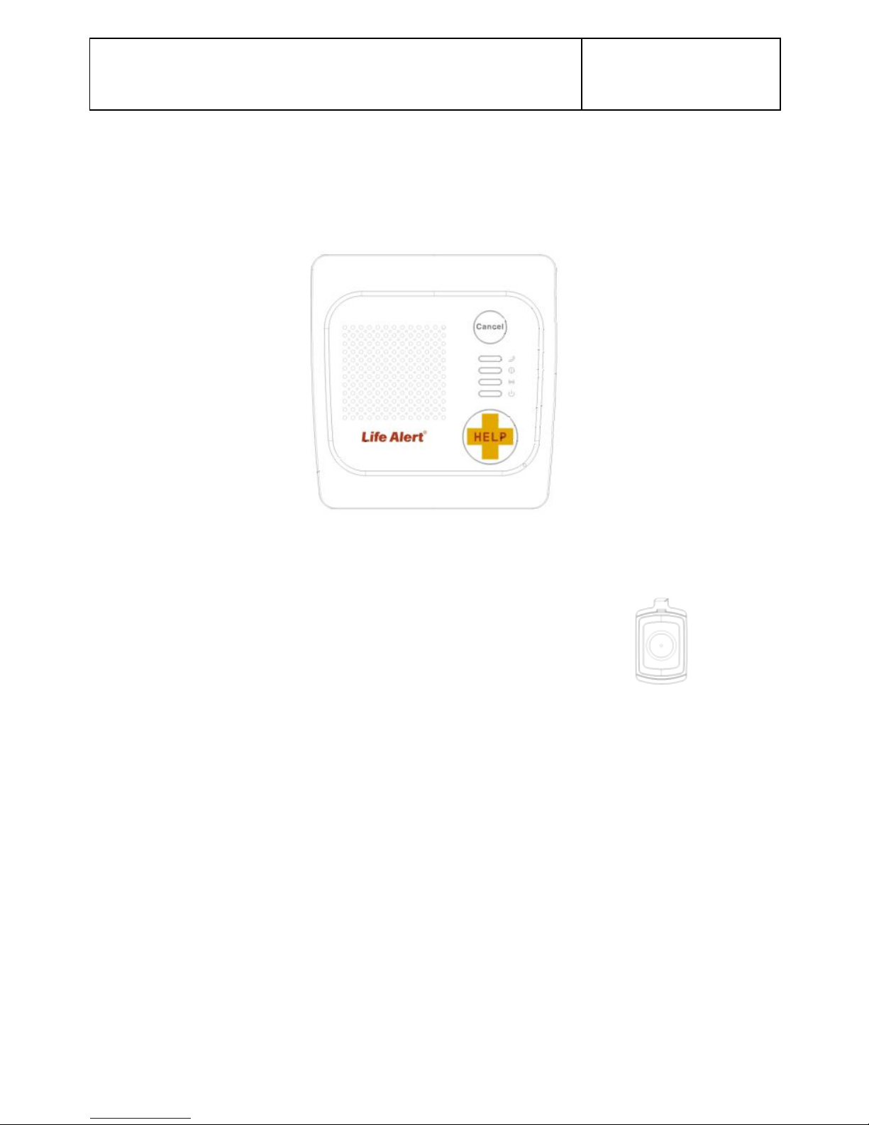
What's Included
Before you begin to set up your system, make sure you have all the
necessary components.
Life Alert Help Pers Unit
Input 120VAC 60 Hz / Output 5V DC 1000 mA
Pendant transmitters supplied with necklace or wrist band
Pendant LATR-01
2
SPECIFICATIONS
General Data
Pendant Transmitter Battery Life: 6 years (for typical
use)
Frequency (MHz): 315.
Note: The 315 MHz version only was tested for
compliance with UL standards.
Indicators: 4 LED indicators.
UL Compliant:
Battery Pack: NI-MH 3.7 V, 2.0 Ah
Supply Voltage: 5VDC , 1A (via 120VAC/60Hz
transformer)
Compliance: Complies with FCC part 68 and part 15,
and UL 985 Home Health Care Signaling Equipment.
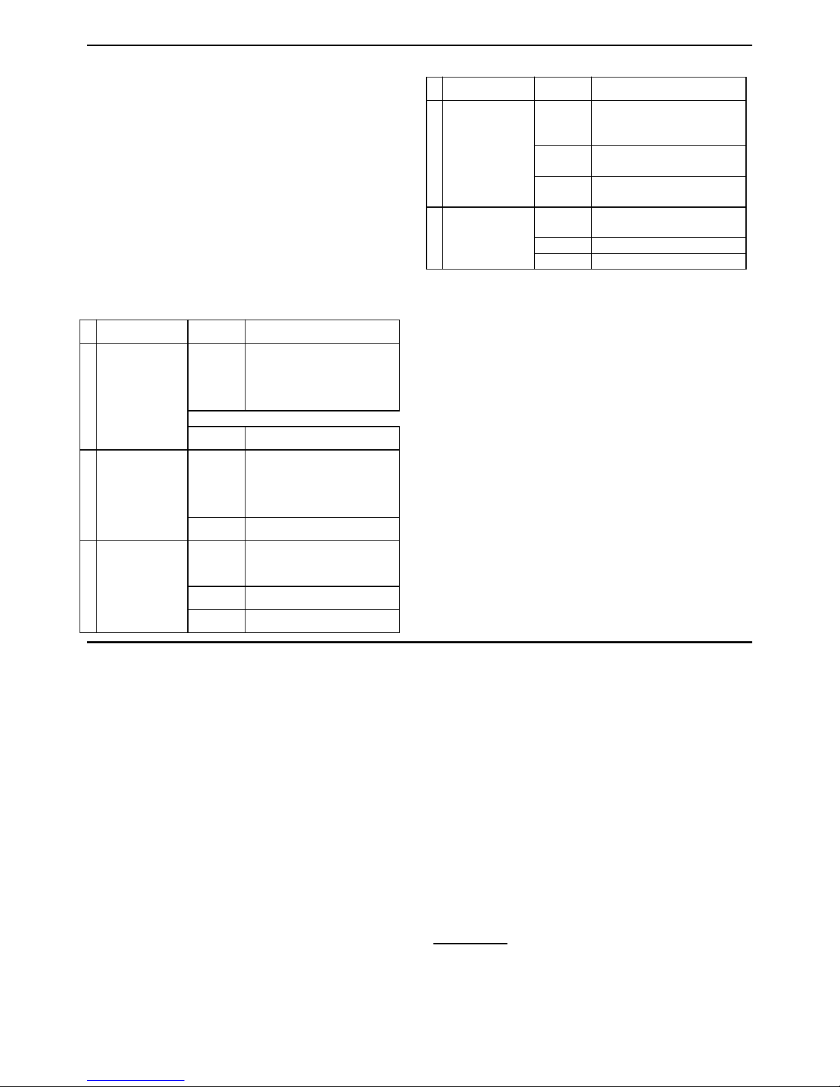
LEDs:
Indicator
Behavior
Significance
RF LED
Lights
steadily
for 3 sec.
Received RF
signal
No light
No RF signal received.
2
Trouble LED
Lights
steadily
Blinks
Indicates all system
troubles
No light
No trouble.
3
Communication
LED
Light
steadily
Communication with call
center established
Blinks
Contacting Call Center
No light
Communication via
Cellular is offline
4
Power LED
Lights
steadily
AC power is connected.
Blinks
Battery problem
No light
AC power is not
connected.
5
Backlight LEDs
Lights
steadily
When the conditions
below do not exist.
Blinks
No AC Power , on battery
operated
Special Functions:
- Calling for help by using an emergency pendant
transmitter
- Speakerphone (hands-free) when communicating
with Life Alert Call Center
- The system supports up to 15 users (pendant
transmitters and smoke detectors).
- Computer control and data download/upload
- Remote control by SMS commands
- Remote diagnostic and event log using a PC
software or SMS
Physical Properties
Operating Temperature: 32F to 104F (0C to 40C)
Storage Temperature: -4F to 140F (-20C to 60C)
Size: 179.5 x 185.5 x 50mm
Weight: 658 gram
Color: White
Note: The product supports Life Alert monitoring center
receivers.
SYSTEM SETUP
To set up your system, follow the steps below.
Select Unit Location
If possible, select a central location in your home for the
Unit. This location should be in the area where you
spend most of your time. The location should also
enable an optimal signal reception for pendants,
smoke , CO detectors and Cellular network .
The Unit can be placed on a table, desk, or counter. It
also can be mounted on a wall.
Make sure that the location you have selected is near
an electrical outlet.
Connect Power to the unit
During normal operation, the unit runs on electrical
power.
1. Insert the plug on the power cord into the "AC"
connector on the unit.
2. Connect the AC/DC adapter into a nearby electrical
outlet. DO NOT USE AN OUTLET CONTROLLED
BY A WALL SWITCH.
5. Turn the ON/OFF switch to ON.
The Unit is now connecting you to
the Monitoring Center
After you complete the steps above press the Help
button, the unit will automatically call Life Alert call
center and the dispatch will be in touch with you .
Transmitters Enrolling
Without PC:
Up to 15 wireless devices / transmitters can be enrolled
locally without a PC. The unit will recognize the device
3
type according to it's ID:
1. Press and hold for 5 seconds both the "CANCEL"
button and ‘’Help ‘’ button. All 4 LEDs should flash
slowly to indicate that the system is in programming
mode.
2. To select the desired transmitter location (zone)
number, click ’’Cancel’’ button repeatedly until the
desired transmitter location number is displayed (see
Table below).. Each press advances to the next
location (zone) number (1 - 15).
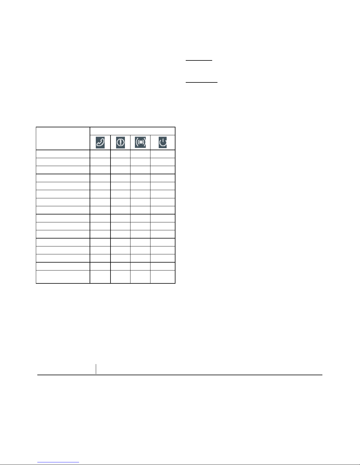
The LEDs lights combination indicates the Location /
zone number, as shown in the following Table:
Flashing light = Free location into which a
transmitter can be enrolled.
Steady light = Occupied location with an enrolled
transmitter.
Table 1 - Zone Number Indication
ZONE
No.
LED
1
ON
–––
2
–ON–
–
3
ON
ON
–
–
4
–
–ON–
5
ON–ON
–
6
–
ON
ON
–
7
ONONON
–
8
–––
ON
9
ON
–
–
ON
10
–ON–
ON
11
ON
ON–ON
12
–
–
ON
ON
13
ON–ON
ON
14
–
ONONON
15
ONONON
ON
16 (Global Zones
clear)
–––
–
3. When the LEDs of the desired location flash, activate
the desired transmitter. Success beeps should be
heard and the proper LEDs combination (see Table
1) should stop flashing and light constantly.
4. To verify that the specific transmitter was properly
enrolled, reactivate the transmitter once again and
verify that all 4 LEDs flash once (in a sequential
manner) and then the LEDs combination
corresponding to the transmitter location return to
light constantly as before.
5. Perform steps 3 - 5 for all other desired transmitters.
6. Exit from programming mode by pressing and
holding for 5 seconds both the "CANCEL" button and
‘’Help’’ button (automatic exit by time out will occur if
no action is performed during 5 minutes).
Deleting Wireless Transmitters
from the System Memory
Using PC:
By using a remote or local PC programmer, it is
possible to delete enrolled wireless transmitters.
Without PC:
Locally (without PC), wireless transmitters can be
deleted from the unit memory, as follows:
1. Press and hold both the "CANCEL" button and
‘’Help’’ button for 5 seconds. All 4 LEDs should flash
slowly to indicate that the system is in programming
mode.
2. To select the desired transmitter to be deleted, click
‘’Cancel’’ button repeatedly until the desired
transmitter location number is displayed (see Table
1). Each press advances to the next location (zone)
number (1 - 15).
3. To delete a selected transmitter, press and hold the
"CANCEL" button for 2 seconds approximately until
the proper LEDs combination will be switched off. As
a result, the LEDs combination of the respective
deleted location (see Table 1) will flash indicating the
location is now free.
Wireless Devices Test
1. Press and hold both the "CANCEL" button and the
‘’Help’’ button for 5 second. All 4 LEDs should flash
to indicate that the system is in programming
mode/Test mode.
2. Activate the transmitter you wish to test and listen to
the system response.
3. Press on ‘’Help’’ button for 2 seconds – the unit will
show the cellular RSSI level .
The unit will play current RSSI level ; Strong ,
Good or Poor . The led indication will show the
RSSI level accordingly:
a. Strong – 4 leds light
b. Good - 3 leds light
c. Poor - 2 leds light
d. Sim card or network problem – 1 led lights
4. Exit the test by pressing and holding both the
"CANCEL" button and ‘’Help’’ button for 5 seconds
(automatic exit by timeout will occur if no action is
performed during 5 minutes).
Using your HELP PERS
Your unit is the communication center of your system.
When your pendant transmitter or smoke detector
signals to the unit , then it contacts Life Alert Monitoring
Center to report the emergency event.
The unit includes the following buttons.
HELP – When pressed, an emergency alarm is
reported to the Life Alert Center or to private phones.
CANCEL – Cancel emergency call
Using your Pendant Transmitter
The pendant transmitter can be used to initiate an
 Loading...