

Page 1
Page 2

Page 3
Safety Guide
Installation of Parts Guide
Installation Instructions
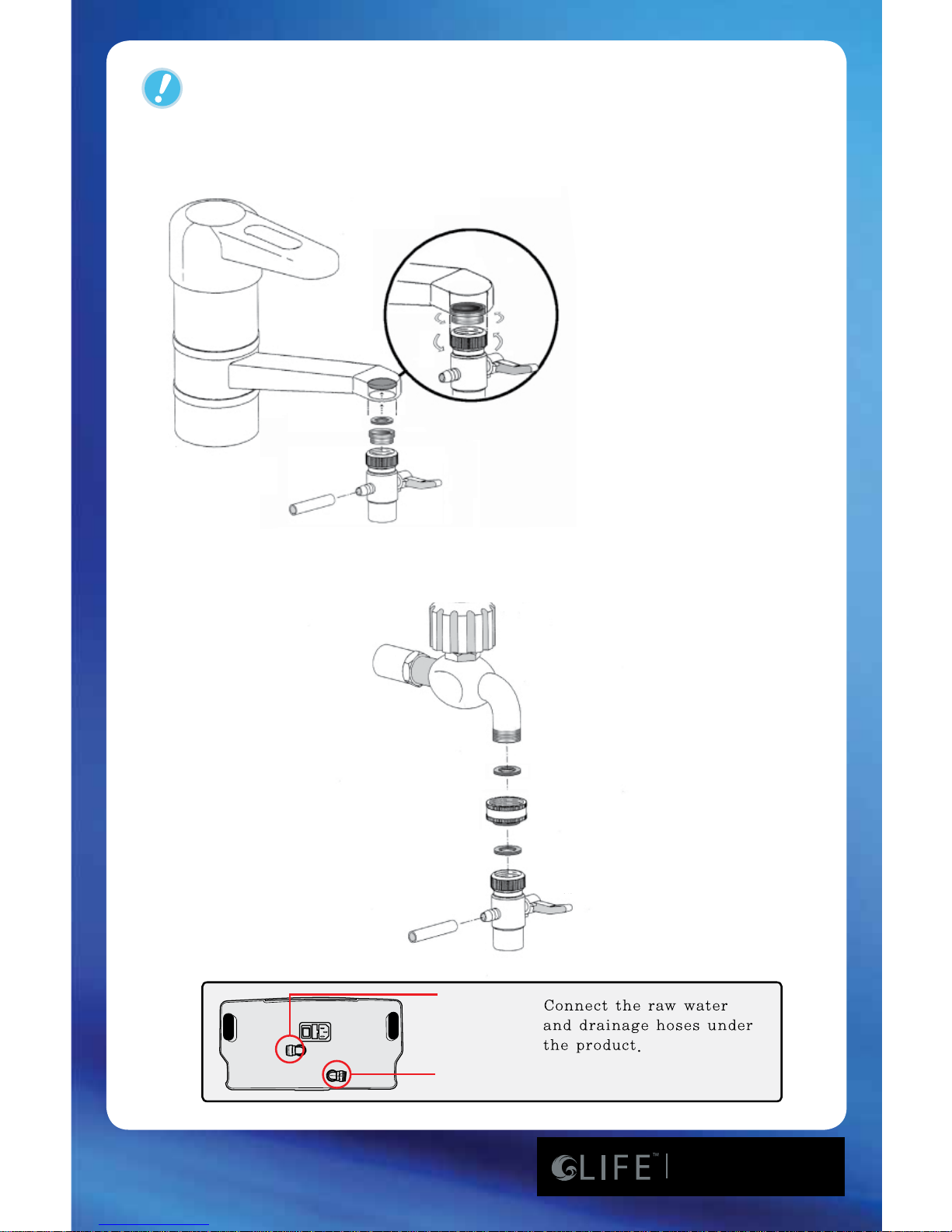
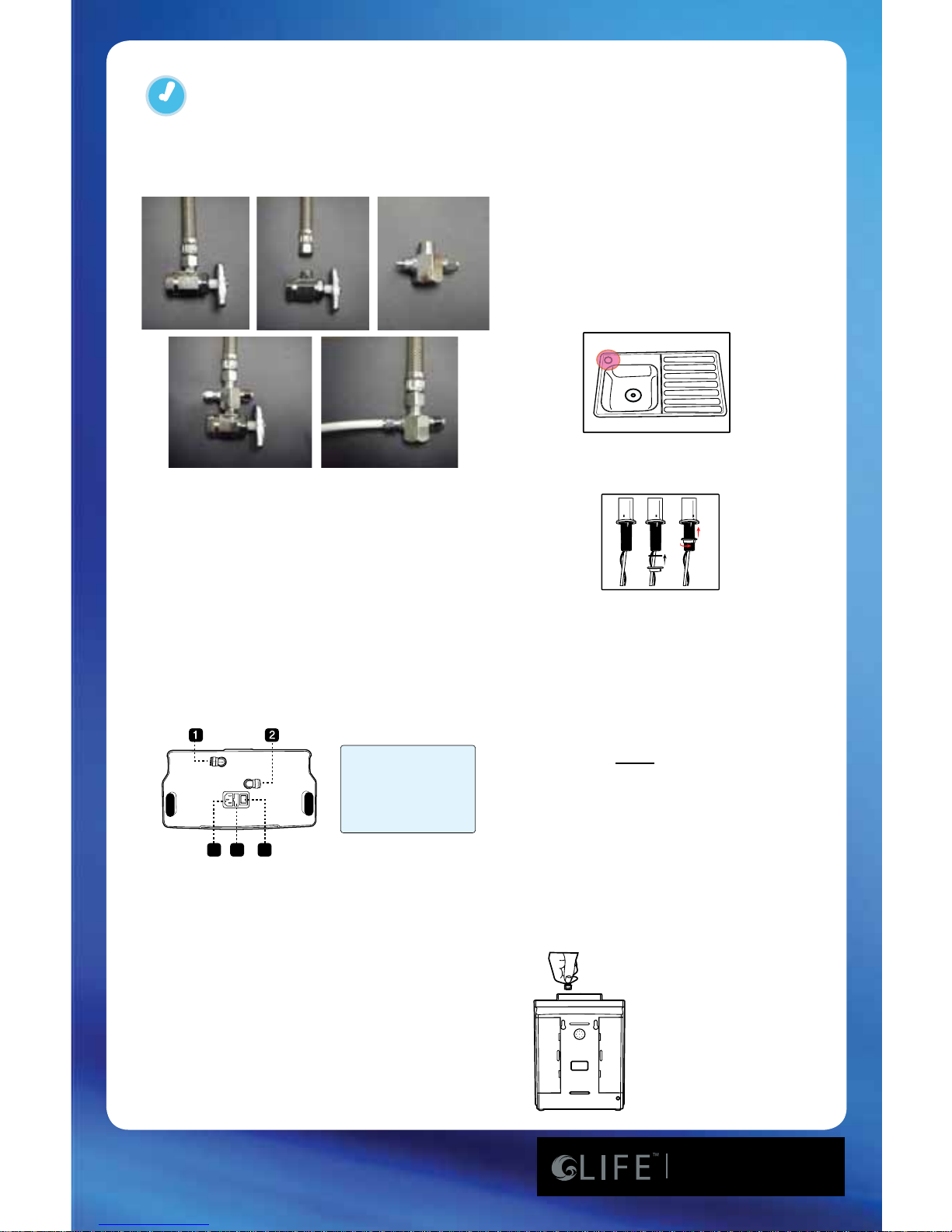
Installation Guide
Indicator Functions
Operation Method
Parts of the Ionizer
Operation Warnings
Production of Ionized Water
7600 to 8100 Conversion
Operation Warnings
Installation Guide for 8100
Operation Method
Indicator Functions
Installation of the Pre-Filter
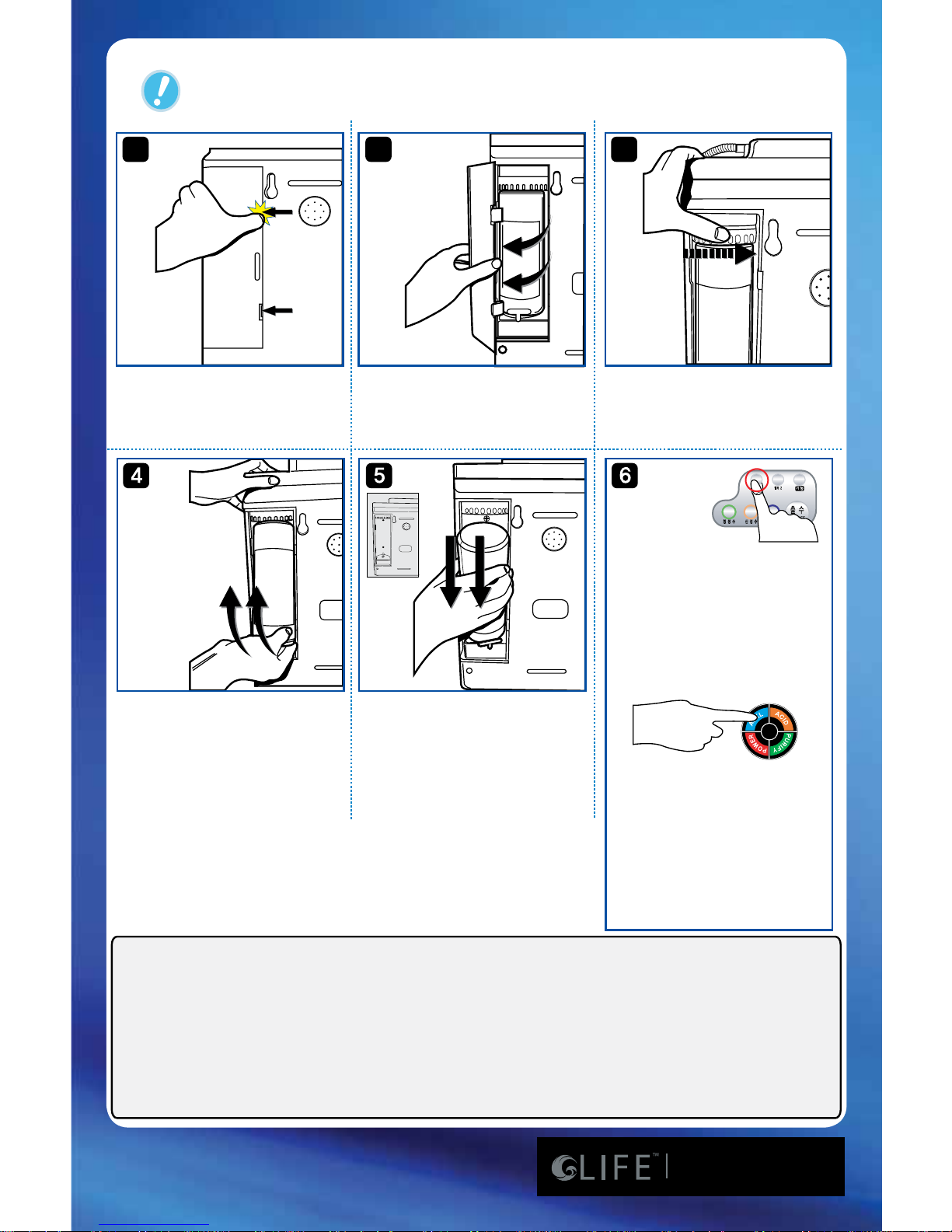
Internal Filter Replacement
Filters
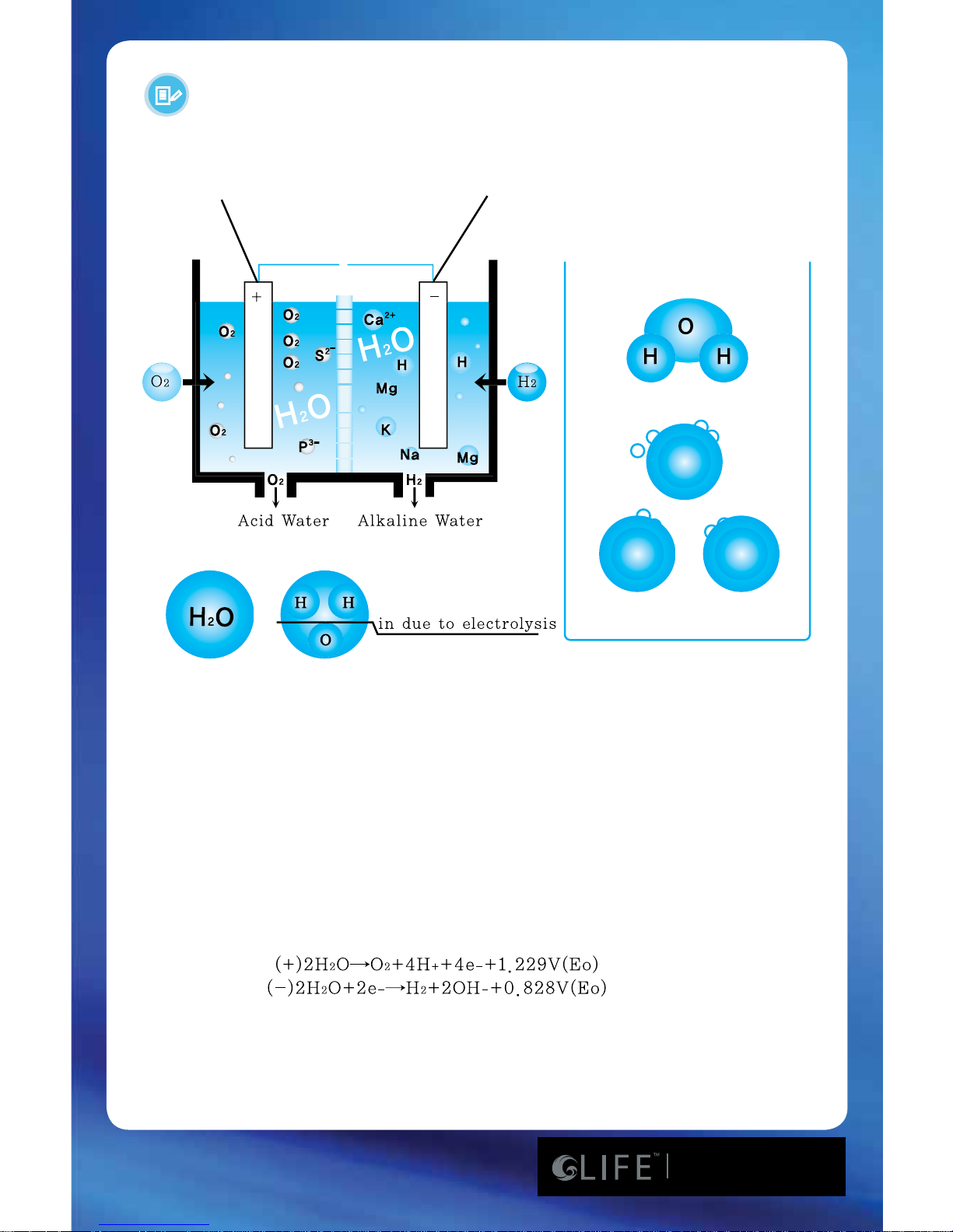
Explanation of Ionized Water
Alkaline and Acidic Water Usage Guide
Uses of Ionized Alkaline/Acidic Water
Performance Features
Common Problems and Solutions
Acidic Cleaning Instructions
& Routine Maintenance
Frequently Asked Questions
4-8
9
10
11
12
13
14
15
16
17
18
19
20
21
22
23
24
25
26
27-29
30
31-32
33
34-45
Table of Contents
Page 4
www.LifeIonizers.com/Support
4
Safety Guide - Read Completely
Before installation or operation of the LIFE IonizerTM, read this
instruction manual completely.
Note- Some parts may have been altered to improve product quality,
function or ease of use.
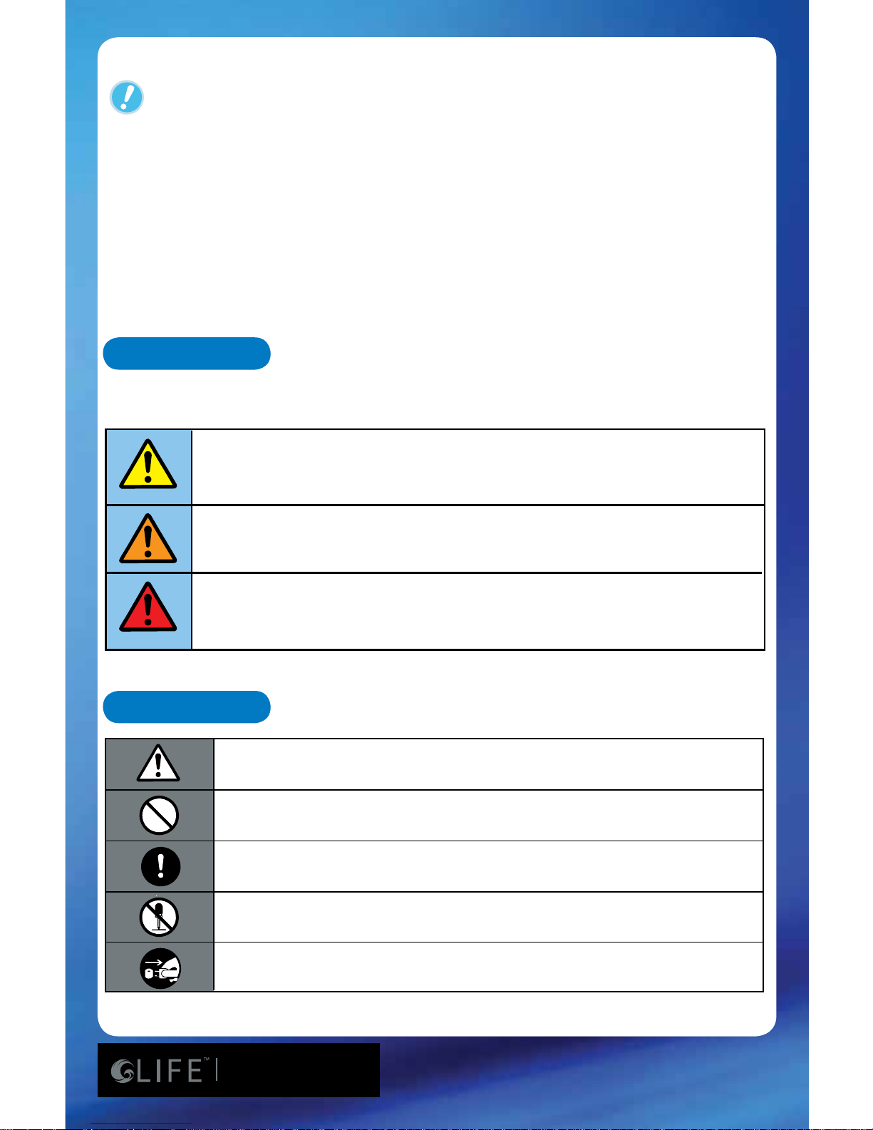
Symbols
Indications
Refer to the following key symbols and indicators throughout the manual.
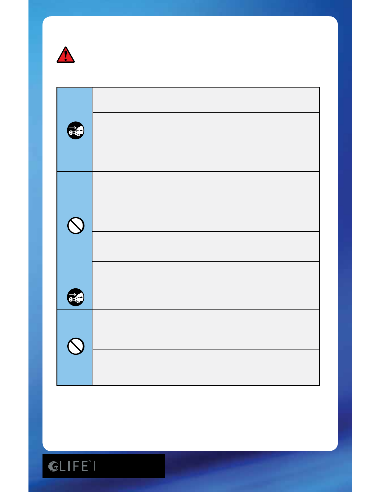
Improper use may cause bodily injury
Improper use may cause structural damage to the unit
or physical injury
Caution, warning, danger symbol
Information on prohibited functions and uses
Make note of important information
Do not open as it may cause electric shock or other injury
Disconnect power plug in case of malfunction
75
7600/8100/8200
As with most electrical appliances, electrical parts in
this ionizer are electrically live even when switch is o.
Page 5
www.LifeIonizers.com/Support
5
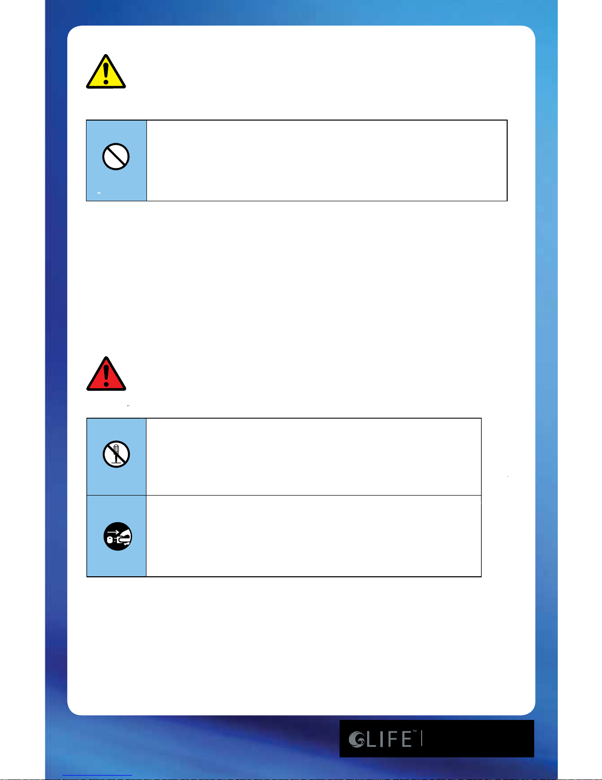
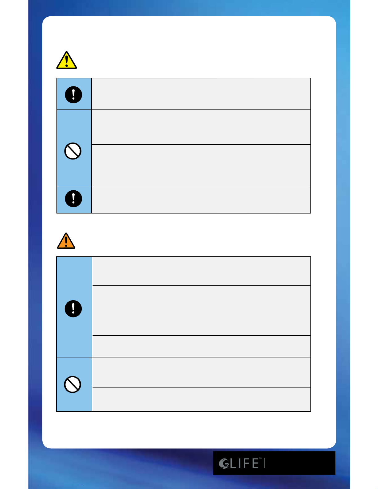
Improper use may cause bodily injury
When drinking Ionized Alkaline Water - Do not take
prescription or other medications for approximately one
hour before and after drinking water.
This machine should not be repaired or otherwise
disassembled by any unauthorized person as it
may cause electrical re or shock, and will void the
manufacturer’s warranty.
Do not place the machine in humid areas such as
bathrooms. Do not clean this machine by spraying
the ionizer with water as it may cause electrical
shock.
75
7600/8100/8200
As with most electrical appliances, electrical parts in
this ionizer are electrically live even when switch is o.
Page 6
www.LifeIonizers.com/Support
6
Power cord should not be touched with wet hands.
Power cord should be plugged directly into an electrical
outlet.
Do not connect multiple appliances into a single power
receptacle.
Dusty or dirty electrical outlets may cause safety issues.
Bending, twisting, pulling or putting heavy objects onto
the power cord may cause electrical problems including
re.
If power cord, plug, or electrical outlet are damaged,
discontinue use immediately.
If the ionizer machine falls into water-
1. Unplug power cord from electrical outlet
2. Wipe the machine down and place in shaded area
3. Contact your LIFE Ionizer
TM
dealer
Use only (110v) in the U.S.A. and Mexico. Use (100v) in
Japan. Most other countries require (220v). The power
cord cannot be altered from manufacturer’s specs.
Do not crimp or staple the power cord as it could cause
electrical shock.
75
7600/8100/8200
As with most electrical appliances, electrical parts in
this ionizer are electrically live even when switch is o.
Page 7
www.LifeIonizers.com/Support
7
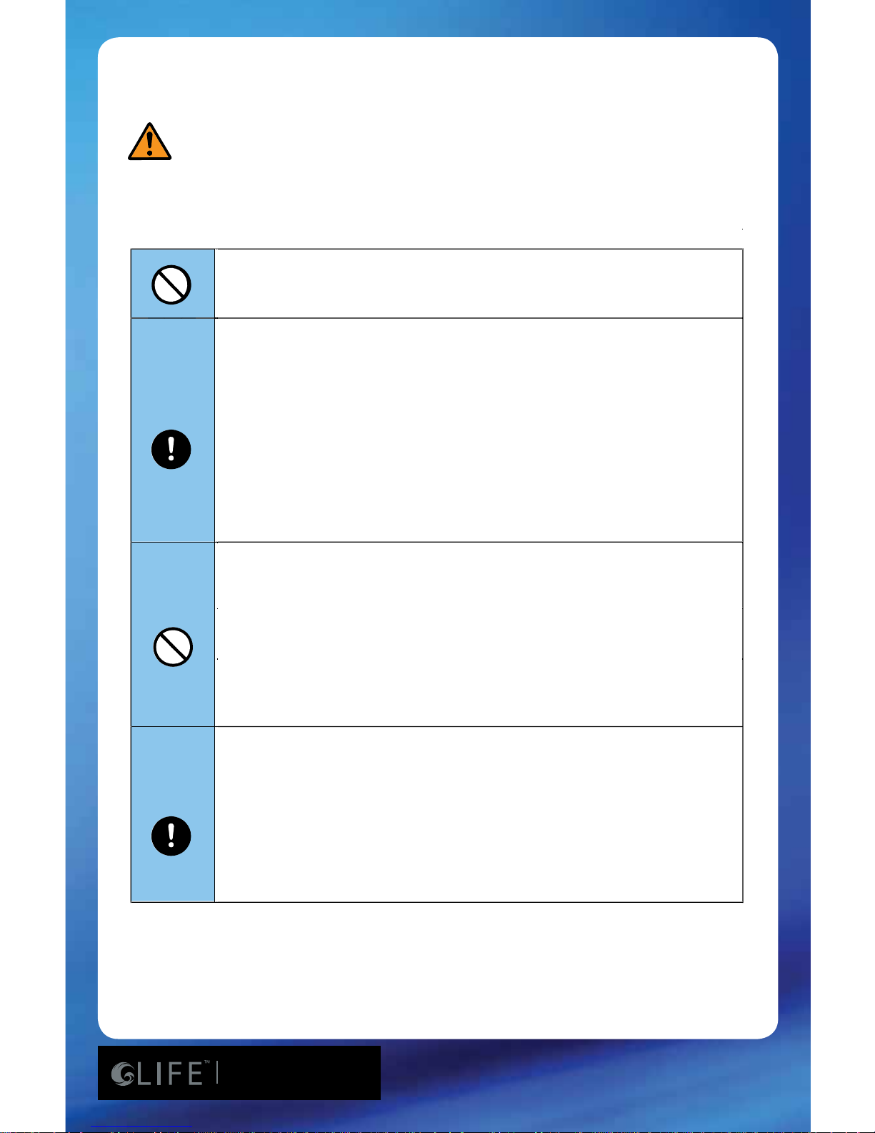
Improper use may cause bodily injury
Improper use may cause structural damage to
the unit or physical injury
Place machine in an upright position only.
If not used for several days, run water through the
unit for 1 to 3 minutes before starting.
Do not install this unit in direct sunlight or near a
heater, replace or other heat source.
Do not use water with a temperature of over 104
degrees Fahrenheit or 40 degrees Celcius.
Store Ionized Alkaline Water in an air-tight glass
container and refrigerate for up to 2 days.
If inexperienced with drinking Ionized Alkaline
Water, users are encouraged to start with lever 1.
DO NOT DRINK ACIDIC WATER.
If wall mounted, secure rmly and correctly.
Do not store Alkaline or Acidic water in metal
containers.
75
7600/8100/8200
Page 8
www.LifeIonizers.com/Support
8
Aluminum and brass containers will be tarnished by
Alkaline and acidic water.
Improper use may cause structural damage to the unit
or physical injury
Do not block the unit vent as it can cause overheating
and/or electrical problems.
Do not use benzene, thinner, or chemicals to clean the
unit as it can damage the housing.
Do not block the water passage or tubing.
If the machine will not be used for several days...
1. Unplug the power cord from the electrical outlet
2. Turn o the water valve to avoid leaking
3. Remove lters, drain and place in refrigerator in
plastic bags.
When handling the pH test (reagent drops)
1. Keep away from eye area. If eyes become irritated,
ush thoroughly and consult a doctor.
2. If accidentally swallowed, drink water and consult a
doctor.
3. Store in an airtight container away from the reach of
children.
4. Drops are ammable. Keep away from children.
75
7600/8100/8200
Page 9
www.LifeIonizers.com/Support
9
1. Refer to the diagrams on the following page before beginning
installation.
2. Be aware that a 110v outlet (USA) or 220v outlet is required. If
the outlet is located under the sink, make sure it is not near
the water source.
3. If after installation the water has an odor, you may need to
install a pre-lter. Please consult your LIFE IonizerTM dealer.
4. How to use reagent drops. (BTB Chemical). Put 2-3 drops in
approximately 1 ounce of water to be tested. Compare color
to color chart provided in kit to determine pH level.
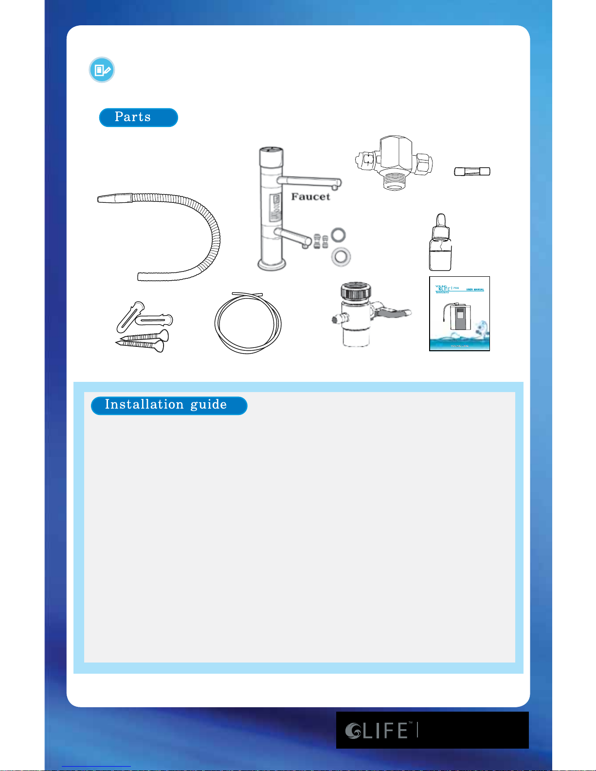
EXTRA
FUSE
Reagent Drops
(pH Test Drops)
Flexible Hose
Wall - Mount Nail
Tubing Hose
Diverter
User Manual
BTB Chemical
Installation of Parts Guide
(for 8100)
Diverter Valve
75
7600/8100/8200
Page 10

www.LifeIonizers.com/Support
10
Installation Instructions for LIFE Ionizer
TM
7600
Use Cold Water Only With Your Ionizer
STEP 1: Unscrew the existing aerator from your faucet.
STEP 2: Use teon plumbers tape on the threads. Screw the LIFE
IonizerTM diverter valve onto your faucet. Three dierent
sized adaptors are included for non-standard sized faucets.
STEP 3: Unscrew the round nut from the side of the diverter valve.
Slide the nut over the end of the 1/4” tubing and then screw
the nut back onto the diverter valve. Tubing should now t
snugly onto the diverter valve.
STEP 4: Lay the ionizer down on its back and you will see two white
elbows extruding from the bottom of the machine. There
will be an o-white collar around the base of the elbow.
Depress the collar towards the machine while simultaneously
extracting the elbow from the machine. Now, holding the
elbow in your hands, you’ll see a similar collar near the end
of the elbow. In the same way as you extracted the elbow,
you can depress the collar towards the elbow and extract
the plug from the end of the elbow. It is sometimes helpful
to use the back of a butter knife or screw driver to remove
the plug. If you ever need to remove the tubing from the
quick release, you will use the same process.
STEP 5: Run tubing from the diverter valve to the inlet valve on the
bottom of the ionizer. Be sure to push the tubing into the
quick connect valve 3/4” until it is rmly seated.
STEP 6: Insert one end of tubing into outlet valve on bottom of unit
and run the other end into the sink securing it with the
suction cup provided. Some units may contain water.
Don’t be alarmed; we test units for quality before shipment!
* For installation video, go to http://www.lifeionizers.com/support/LIFE Ionizer 7600 & 8100
75
7600/8100/8200
Page 11
www.LifeIonizers.com/Support
11
C
o
ld
w
a
t
e
r
in
le
t
C
o
ld
w
a
t
e
r
i
n
l
e
t
Assembly method of valve for
wall-mounted water taps
Fix adapter
Quarter turn
for Tap Water
Running
Water
Rubber Gasket
Remove the aerator from the water tap.
Assembly method of valve for Deck-sink water taps
Screw in the adaptor
Remove the aerator from
the water tap.
Connect by rotation
after insertion of rubber
packing
Installation Guide
Cold Water inlet
Assembly method of valve for Deck sink water taps
Assembly method of valve for
wall-mounted water taps
Quarter turn
for Tap Water
Running
Water
Cold Water inlet
Rubber Gasket
Fix adapter
Inlet Valve
Outlet Valve
(Drainage)
75
7600/8100/8200
Page 12
www.LifeIonizers.com/Support
12
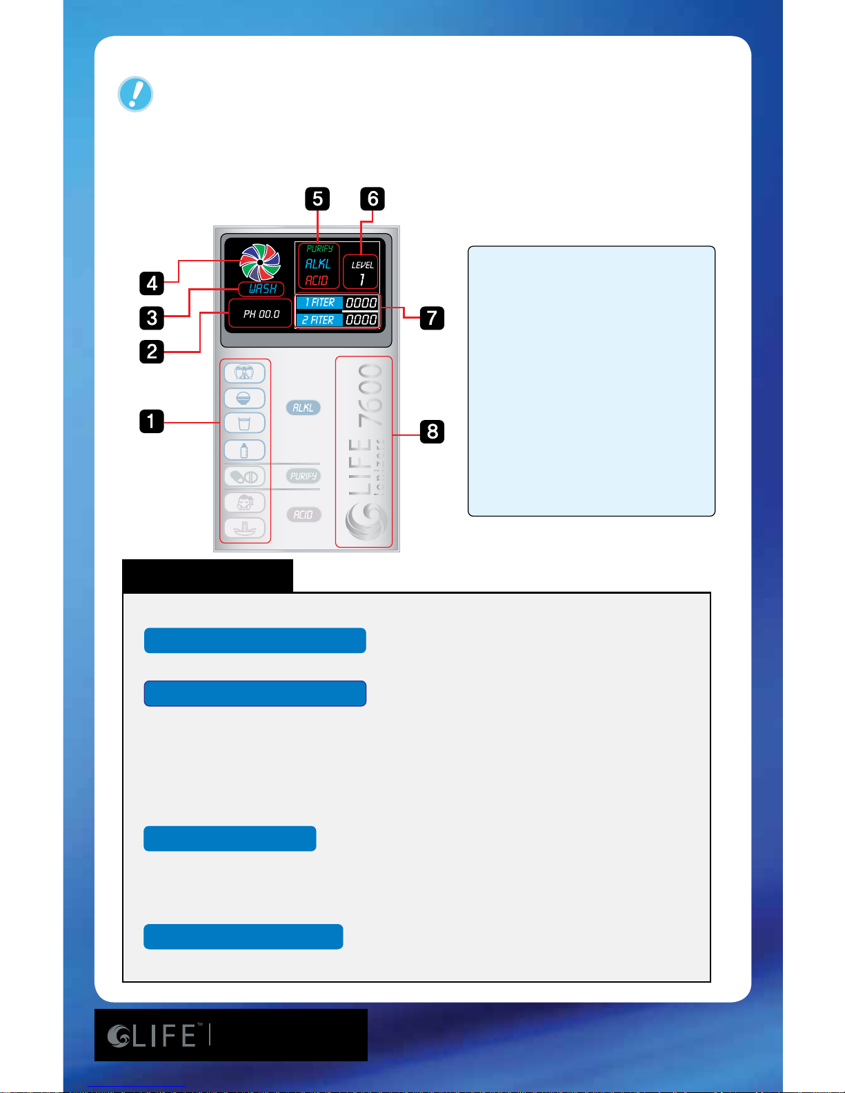
Water Cleaning
Voice Functions
Ionized Alkaline Water
Acid Water Button
Puried Water Button
1. Drinking method indicator
2. pH indicator
3. Indicates “Being Washed”
4. Rotates while cleaning
5. Indicates ion water type
(Alkaline, acidic, puried)
6. Indicates selected
ionization water setting
7. Filter life - indicator
8. LIFE IonizerTM Logo
*Please wait a few seconds… as the machine is cleaning itself.
*4th grade of Ionized Alkaline Water is being extracted now.
*3rd grade of Ionized Alkaline Water is being extracted now.
*2nd grade of Ionized Alkaline Water is being extracted now.
*1st grade of Ionized Alkaline Water is being extracted now.
*2nd grade of acid water is being extracted now.
*1st grade of acid water is being extracted now.
*1st grade of clean water is being extracted now.
Voice: Please wait a few seconds as the machine is cleaning itself.
Indicator Functions
6
75
7600/8100/8200
Page 13
www.LifeIonizers.com/Support
13
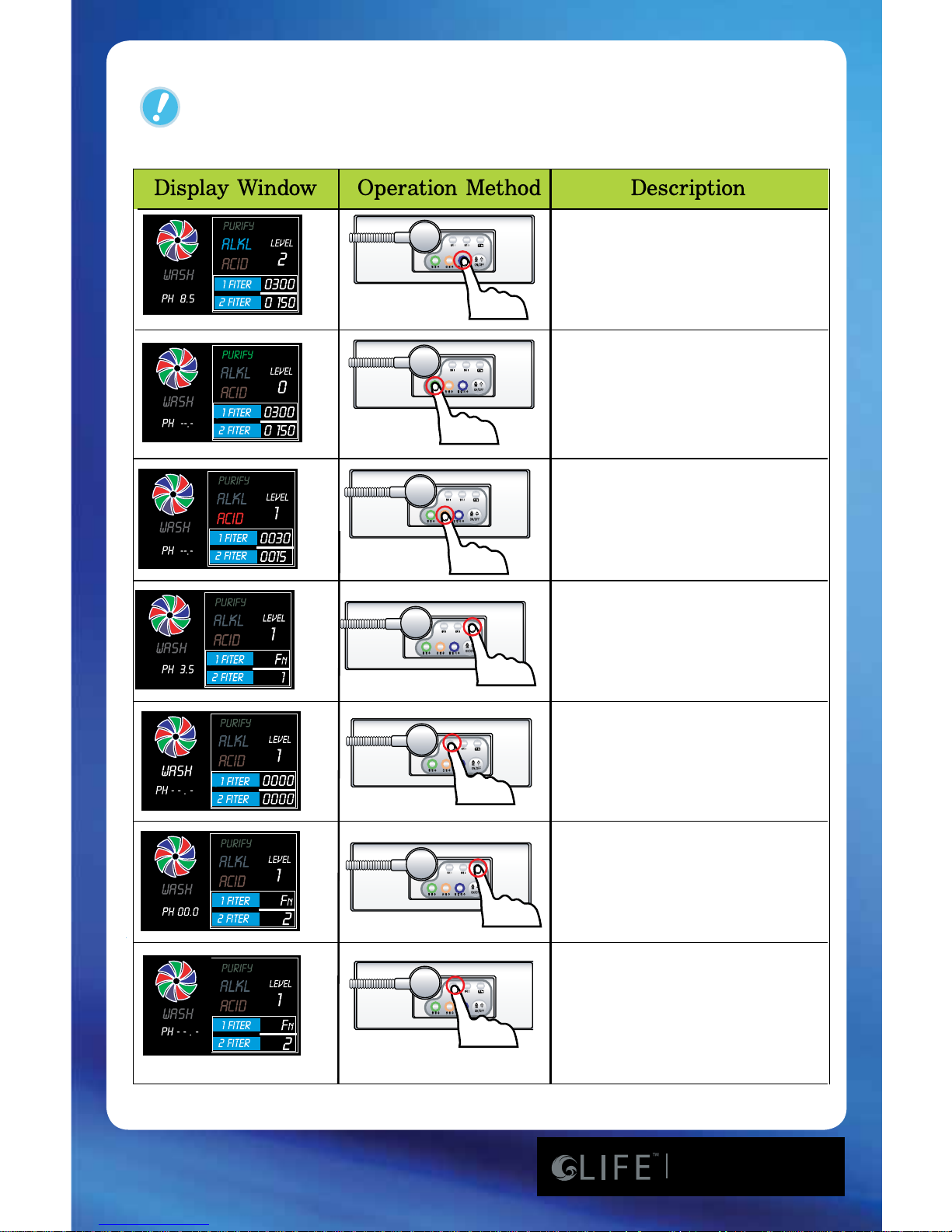
When “CLEAN WATER” is
selected, pH is not indicated.
The “ALKL” and “ACID” LEDs
go o.
When “Alkaline” water is
chosen, Levels 1 to 4 can be
selected by pressing the
“Alkaline” button again.
When “ACID WATER” is
selected, Level 1 or 2 can
be selected by pressing the
“ACID WATER” button again.
When “FUNCTION” is selected,
The menu changes from the
main menu to FN1 and FN2 and
then back to the main menu.
When replacing the lter while
on the main menu, press the “1ST
FILTER” or “2ND FILTER” button
and hold for 5 sec. This resets the
lter counter to 0000. The lter
count goes to 9999.
When FN2 is selected with the
“FUNCTION” button, the amperage
setting can be adjusted from 0
to 4 by pressing the ”2ND FILTER” (increase) and “1ST FILTER”
(decrease) buttons.
FN1 is the volume menu.
Levels 0 to 4 can be selected
by pressing the ”2ND FILTER”
(up) and “1ST FILTER” (down)
buttons to increase or decrease
the volume.
Operation Method
75
7600/8100/8200
Page 14
www.LifeIonizers.com/Support
14
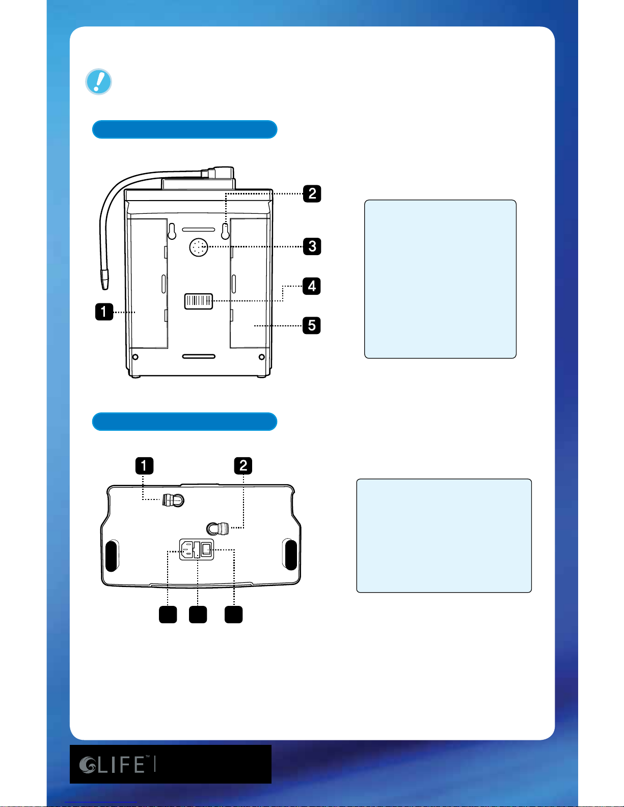
3
4
5
1. First Filter Cover
2. Wall Mount Screw
Holes
3. Speaker
4. Bar Code and Serial
Number
5. Second Filter
1. Outlet valve
2. Inlet valve
3. Power Plug
4. Fuse Box
5. On/O Power Switch
Parts for the Ionizer (Back)
Parts for the Ionizer (Bottom)
xx x- xx xx x- xx -x x
Parts of the Ionizer
75
7600/8100/8200
Page 15
www.LifeIonizers.com/Support
15
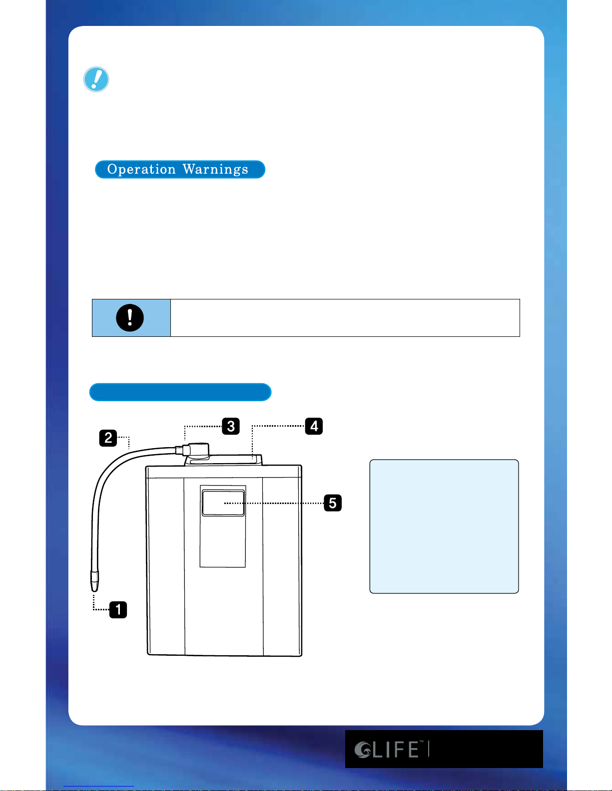
Parts for the Ionizer (Front)
1. Water Spout
2. Water Hose
3. Flexible Hose
Connector
4. Control Panel
5. LCD panel
DO NOT run the following types of water though the LIFE
Ionizer
TM
as it can cause damage to the unit.
1. Dirty or Salty Water
2. Water containing high amounts of rust or iron
3. Water above 40 degrees C or 104 degrees F
Read these instructions thoroughly before attempting
installation.
Operation Warnings
75
7600/8100/8200
Page 16
www.LifeIonizers.com/Support
16
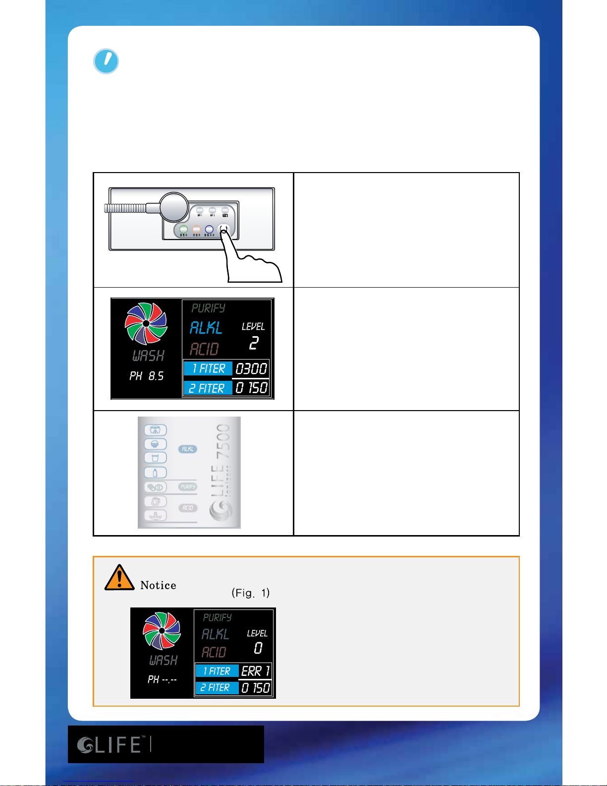
1. Press the main water ow
button on top of the product.
2. Select the water type –
Alkaline, Acidic, or Puried
setting.
3. When the “Alkaline” is selected,
the LCD indicates the Alkaline
setting and level.
When you select the main
water ow button while the
water pressure is low or valve
is closed, the LCD will appear as
“Fig. 1” Please check the water
pressure or valve opening before
proceeding.
4. According to the selected step,
the LED indicates the pH of the
water.
“ERR 1” will appear as shown in Fig. 1 if water pressure is low.
Please check...
Production of Ionized Water
75
7600/8100/8200
Page 17
www.LifeIonizers.com/Support
17
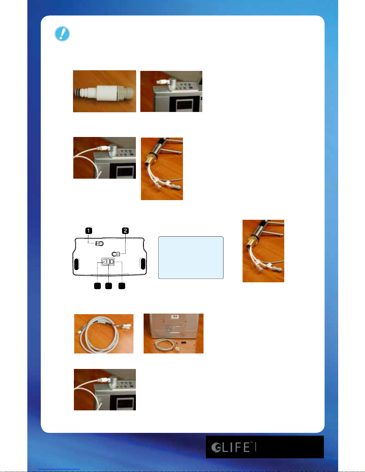
1. Snap in plastic adaptor into top of unit where exible metal hose was in place.
2. Cut a piece of 1/4 inch tubing and connect it to plastic adaptor on top of unit,
then insert other end of tubing into the alkaline tubing connection on faucet.
3. Connect a piece of 1/4 inch tubing from “outlet” on bottom of ionizer, to the
acid connection on faucet.
4. Plug in electrical extension wire into faucet connection and plug in the other
end into the back of the ionizer.
5. Press power button on top of faucet to turn on ionizer.
3
4
5
1. Outlet valve
2. Inlet valve
3. Power Plug
4. Fuse Box
5. On/O Power Switch
Conversion from 7600 to 8100
75
7600/8100/8200
Page 18
www.LifeIonizers.com/Support
18
DO NOT run the following types of water though the LIFE
IonizerTM as it can cause damage to the unit...
1. Dirty or Salty Water.
2. Water containing high amounts of rust or iron.
3. Water above 40 degrees C or 104 degrees F.
Read these instructions thoroughly before attempting
installation.
Operation Warnings
DO NOT run the following types of water though the Life Ionizer as it
can cause damage to the unit:
1. Dirty or Salt Water
2. Water containing high amounts of rust or iron
3. Water above 40 degrees C/104 degrees F
Read these instructions thoroughly before attempting
installation
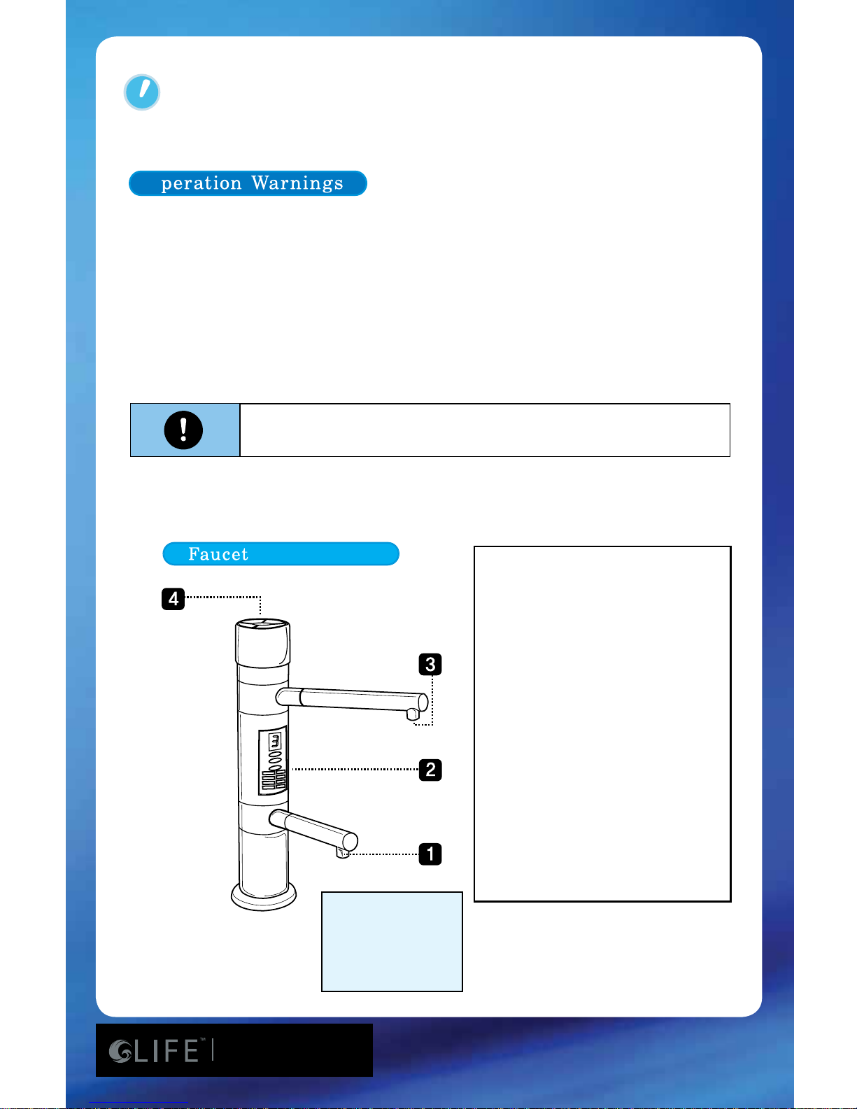
1- Acid Water Spout
2- Digital Indicator
3- Alkali Water Spout
4- Control Panel
1- Water Spout
2- Digital Indicator
3- Water Spout
4- Control Panel
Please note that water will come
out of both spouts when dispensing
water.
A) When the Alkaline button is
pressed, Alkaline water will be
dispensed from the top spout and
acid water will be dispensed
from the bottom spout.
B) When the Acid button is pressed,
Acid water will be dispensed from
the top spout and Alkaline water
will be dispensed from the bottom
spout.
C) When the purify button is pressed,
puried water will be dispensed
from the bottom and top spouts.
75
7600/8100/8200
Page 19
www.LifeIonizers.com/Support
19
How to Connect the Angle Stop Adapter Valve
1. Shut o cold water supply by turning supply valve in
the o direction.
2.
Disconnect supply valve from cold water supply hose.
DO NOT connect this unit to the hot water supply.
Ensure that the sealing gasket is fully seated into the
Angle Stop Valve female thread.
3. Install Angle Stop Adapter Valve on supply valve.
4. Connect the Angle Stop Adapter Valve to cold water
supply hose.
5. Connect white tubing to cold water diverter value.
Water ow adjustment screw is located opposite side of
white tubing.
6. Lay the ionizer down on its back and you will see two white el-
bows extruding from the bottom of the machine. There will be
an off-white collar around the base of the elbow. Depress the col
lar towards the machine while simultaneously extracting the
elbow from the machine. Now, holding the elbow in your hands,
you’ll see a similar collar near the end of the elbow. In the same
way as you extracted the elbow, you can depress the collar to
wards the elbow and extract the plug from the end of the elbow.
It is sometimes helpful to use the back of a butter knife or screw
driver to remove the plug. If you ever need to remove the tubing
from the quick release, you will use the same process.
Note- If installing a pre-lter, the pre-lter should be installed
between the cold water supply and the water inlet valve at the
bottom of the unit. See diagram and instructions on page 22.
7.
Installation Guide for 8100
* For installation video, go to http://www.lifeionizers.com/support/LIFE Ionizer 7600 & 8100
Connect the other end of the tubing from
the Speedt
TM
side of the valve to the
water inlet (white elbow-quick connect)
located on the bottom of the ionizer.
Push the tubing into the elbow as far as
you can; approximately 3/4 of an inch.
The tubing and the elbow will self-seal.
If your sink/counter does not have a
hole for the faucet, select a location and
drill a 1 3/8 in. hole.
Place the faucet through the drilled
hole. From under the sink slip washer and
nut over the tubing and screw on tightly
to bottom of counter.
On the top of the machine, you will notice there is a white plug in the ALKALI inlet
and there is a white plug in the ACID inlet.
These two plugs need to be removed
before you can install the tubing. On the
machine, there is a collar just under the top
of the plug. Depress the collar towards the
machine while simultaneously pulling the
plug out the machine. It is sometimes helpful to use the back of a butter knife blade or
a very thin, at screwdriver to push down
on the collar while you pull out the plug.
8.
9.
Connect the thicker tubing
running from the faucet
to the alkali connector at
the bottom of the unit, the
thinner tube to the acid
connector, and the electrical
connection to the back of
the unit.
10.
11.
3
4
5
1. Outlet valve
2. Inlet valve
3. Power Plug
4. Fuse Box
5. On/O Power Switch
1.
2.
3.
4. 5.
75
7600/8100/8200
Page 20
www.LifeIonizers.com/Support
20
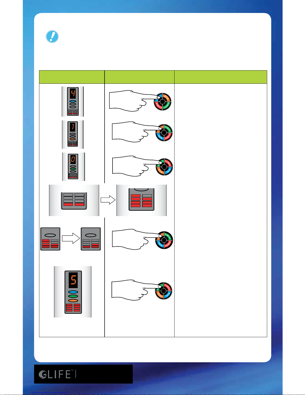
Operation Method
When you select alkaline water.
1~4 phases appear in number
and light is marked by blue
color.
When you select acid water,
1~2 phases apear in number
and light is marked by orange
color.
When you select puried water,
the number and light is marked
by green color.
The lifetime of the lter is
shown by four phases of light.
You should change the lter
when only one bar is not lit up.
* After changing the rst lter, you
can reset it by pushing the
acid button for 5 seconds.
* After changing the second lter;
you can reset it by pushing the
alkali button for 5.
For sound control, all alkaline,
acid, puried water lights will be
turned on if you push the puried
button for 5 seconds. After that, if
you push the acid button, the volume will decrease. If you push the
alkaline button, the volume will
be increase. This can be controlled
from 0 to 5 seconds.
DISPLAY WINDOW OPERATION MENU DESCRIPTION
Early stages of lter life.
In need of lter change.
75
7600/8100/8200
Page 21
www.LifeIonizers.com/Support
21
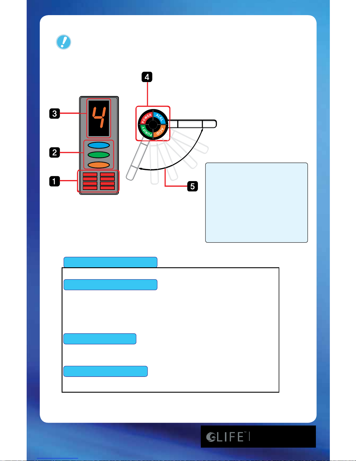
Voice Functions
Indicator Functions
1. Filter Indicator
2. Indicates Ionized Water Type
3. Indicates Selected
Ionization Water Setting
4. Ionization Water Selection
Button
5. The Faucet Can Swivel Up
to 120
o
*It is being washed now, Please wait a minute.
*Alkaline 4 - 4th grade of alkaline water is being extracted now.
*Alkaline 3 - 4th grade of alkaline water is being extracted now.
*Alkaline 2 - 4th grade of alkaline water is being extracted now.
*Alkaline 1 - 4th grade of alkaline water is being extracted now.
*Acidic Water 2 - 2nd grade of acid water is being extracted now.
*Acidic Water 1 - 1st grade of acid water is being extracted now.
*Puried Water is being extracted now.
Alkaline Water Button
Acid Water Button
Puried Water Button
75
7600/8100/8200
Page 22
www.LifeIonizers.com/Support
22
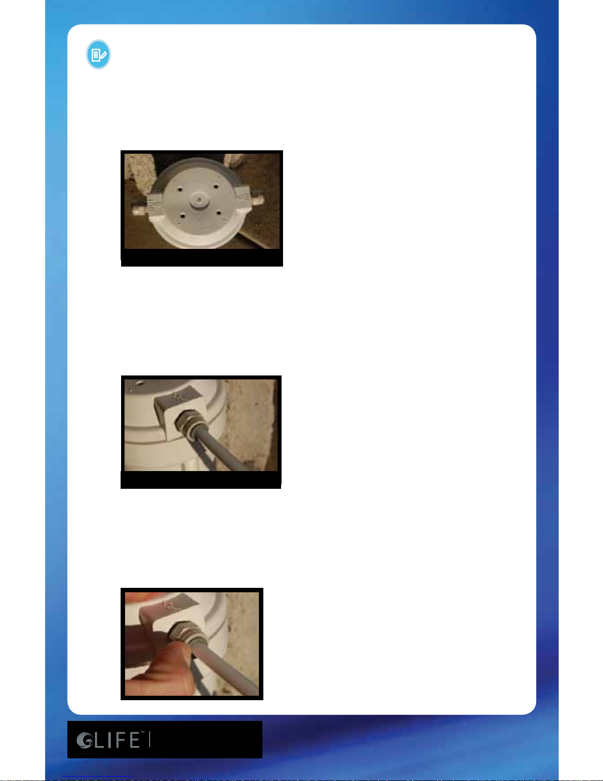
1. Cut the tubing leading to the ionizer at the desired location and length.
2. The cap on top of the lter housing is marked “OUT” and “IN”.
3. The tubing coming from the cold water connector needs to be inserted into the
side of the housing marked “IN”. Firmly press the tubing into the lter-housing cap.
You will feel the tubing stop when it is fully inserted. Pull on the tubing gently to
ensure that it does not come out and a good connection was made. If possible,
ush the lter by turning on the ow of water slowly and point the “OUT” towards
the sink; let it run for 2-3 minutes and turn the water ow o.
4. Insert the tube going to the ionizer into the side of the housing marked “OUT” by
rmly pressing the tube into the lter housing cap.
5. To remove the tubing from the lter cap, press in on the O-ring and tubing simultaneously, then gently pull out on the tubing.
TOP VIEW OF FILTER HOUSING
SIDE VIEW OF FILTER HOUSING
Installation of the Pre-Filter
75
7600/8100/8200
Page 23
www.LifeIonizers.com/Support
23
After replacing lter #1,
press 1st lter button for
8 seconds to reset lter
counter. To reset lter #2,
press down 2nd lter
button for 8 seconds.
Internal Filter Replacement
Press the top and bottom
of the lter cover.
Open the lter cover
following the direction
of the arrow.
Turn the lter top in
the arrow direction.
Insert the new lter
following the direction
of the installation arrow
and turn the lter
bases appropriately.
Lift the lter up and
out following the
direction of the arrow.
Tips After Filter Replacement:
1) Select the “Puried Water” setting and let the water run for 3-5 minutes after any
lter replacement .
2) If the machine has not been used for a few days, let the water run for 3-5 minutes
at the “Puried Water” setting before making Ionized Alkaline water for consumption.
3) Consult with the installer or retailer on the purchase of lters if in question about
usage or installation.
(for 7600)
(for 8100)
After changing the rst
lter, you can reset it by
pushing the acid button
for 5 seconds.
After changing the second
lter; you can reset
it by pushing the alkali
button for 5.
75
7600/8100/8200
Page 24
www.LifeIonizers.com/Support
24
Filters
1. Sediment
Eliminates sediments (mud, rust, sand, etc) 10 microns or
larger.
2. Pre-Carbon
Absorbs and eliminates various compounds, remaining
chlorine, taste and odor, THM, etc.
3. Activated Carbon Filters
Ultra-ne coconut shell carbon and silver impregnated
carbon.
4. Final Stage Sediment Filter
Reduces lter remnants and remaining sediments.
1. Granule type Carbon Filter
Reduces chlorine taste and odors, fast absorbing, generates
low dust.
2. Pi-Ceramic Negative Ion Filter
Generates negative ions, making water clusters smaller.
3. BioMass ball-Ceramic Filter - High quality ceramic lter
designed for bacteria control.
4. Vitamin C Ceramic Technology
TM
For the reduction of Chlorine and Chloramines.
5. Special Quality Sediment Filter
Prevents sediment discharge.
75
7600/8100/8200
Page 25
www.LifeIonizers.com/Support
25
anode cathode
With electrolyzed water, the cathode (-) produces Alkaline Ionized Water
with minerals (pH scope 7.5~10) - such as Ca, K, Mg, Na, etc. because of
the hydroxyl ion (OH-) generating reaction.
The anode (+) has lots of hydrogen (H+) (pH scope 3.5~6.5) because
the oxygen gas (O2) generates a reaction and acid ion water has many
ions such as Cl, S, P.
The Ionized Alkaline Water and acid ion water made by an electrolytic
reduction water generator, has characteristics like those below.
Explanation of Ionized Water
75
7600/8100/8200
Page 26
www.LifeIonizers.com/Support
26
1. If the machine has not been used for several days, let the water run on the
“Puried Water” setting for at least 3-5 minutes before any operation.
2. First time users who are not familiar with this water are recommended to start
with Ionized Alkaline Water level 1 and adjust the quantity or level of wate
which might t you the best. Increase slowly over time as your body adjusts.
(Level 1 is recommended for rst time Alkaline Ionized water drinkers).
3. Store Ionized Alkaline Water in an airtight glass container and put it in a
refrigerator for no longer than 2 days for maximum benet. The rst 12 hours
after ionization the water is most eective.
Acidic water is not drinkable – DO NOT DRINK
1. Use acid water only for disinfecting, cleaning, plants and as a
face/skin toner.
2. Acidic water properties are the best 1-7 days after ionization if
it is put in an airtight glass container and kept refridgerator.
1. Clean water is chlorine free due to the internal ionizer lters
and ionizer pre-lters.
2. It is best to drink puried water when taking medication.
3. Can a person drink Ionized Alkaline Water when on medication?
-Yes, as a precaution DO NOT DRINK Ionized Alkaline Water 45
minutes to one hour before and after taking medication or
supplements.
Puried Water Usage Guide
Acidic Water Usage Guide
Alkaline and Acidic Water Usage Guide
Please note that water will come out of both spouts when dispensing water.
A) When the Alkaline button is pressed, Alkaline water will be dispensed from the top spout
and acid water will be dispensed from the bottom spout.
B) When the Acid button is pressed, Acid water will be dispensed from the top spout and
Alkaline water will be dispensed from the bottom spout.
C) When the purify button is pressed, puried water will be dispensed from the bottom and
top spouts.
75
7600/8100/8200
Page 27

www.LifeIonizers.com/Support
27
Highly Ionized Alkaline Water: pH 11.0+
Highly Ionized Alkaline Water preserves hygiene in our daily life due to its
strong cleaning eect.
Food Preparation: Wash Vegetables and fruit.
Cleaning: Clean cutting boards with. Good for cleaning oil and tough grime
from vents, as well as for general cleaning in the kitchen.
Stain Removal: The extra strength, absorption power will remove coee,
soy sauce and oil stains with ease. Also great for getting out stubborn toilet
bowl stains.
Dishes: Use less detergent when hand washing dishes. Save on water bills,
as only one-third to one-forth of the usual amount of water is adequate
cleaning and for rinsing with detergent.
pH Water: 8.0-10.0
Absorbing, dissolving and heat conducting benets.
Drinking: Drink 2- cups of Ionized Alkaline Water rst thing in the morning. It is important to include vegetables in your diet. Eating substantial
amounts of acidic food such as egg yolk, white rice, chicken, pork and beef
may be part of your diet. Drinking Ionized Alkaline Water is equally important because it balances the acidic and Alkaline eects of these foods.
Food Preparation: Clean vegetables and sh. Enhance the avor of broccoli, onions, etc. by pre-boiling them in Ionized Alkaline Water. Use less condiments and salt in your diet.
Rice: Use Ionized Alkaline Water for washing and cooking rice. The result is
delicious and uy rice.
Tea: Taste and aroma are everything to many people. You will be
surprised at the improved color, taste, and aroma. You can use less tea and
still achieve a full rich taste.
Uses for Ionized Alkaline Water
75
7600/8100/8200
Page 28

www.LifeIonizers.com/Support
28
Soups and Stews: Ionized Alkaline Water draws out the avor of in-
gredients so they get tender and juicy. Therefore, less seasoning such as
salt and soy sauce are needed. This water is good for people who want to
reduce their salt intake.
Plants: Watering plants and owers. Ionized Alkaline Water extends the
freshness and life of plants. Ionized Alkaline Water with a pH level of 9.0
can also restore the health of sick plants. Ionized Alkaline Water stimulates
germination and improves seeding development.
Animals: Your animal’s health will improve dramatically. Unpleasant
body order will decrease, as well as the odor of feces and urine.
Crafts: Excellent for dyeing cloths, as well as other craft projects. You will
love the vibrant colors obtained when using this water.
Health: Through continuous use, the acidic tendency of your body can
be gradually corrected to an Alkaline levels. Drink at least half your body
weight in ounces in order to gradually change an acidic level to a slightly
Alkaline one.
Colon cleansing: Warm the water to body temperature and use the
colon cleansing unit to remove accumulated debris and waste.
Other Uses: One theory is that this water reduces free radicals. Recently,
this water has been acclaimed as “Free Radical Water”. It slows down aging
and stabilizes body temperature.
pH Water: 7.0
Free of chlorine, rust and cloudiness. Clean water is delicious drinking
water.
Children: Use puried water with a pH of 7.0 when preparing baby food.
75
7600/8100/8200
Page 29

www.LifeIonizers.com/Support
29
pH Water: 4.0-6.0
Face wash: The astringent properties of acidic water are eective in
toning and rming your skin. Pat the skin and leave to dry. This water
is also excellent as a toner after shaving.
Hair Care: Use this water to rinse your hair after shampooing. Reduces annoying tangles and brings out a radiant shine. Keep in a spray
bottle and spray your hair and face when you’re out and about.
Bath Water: Add acidic water to your bath water to keep your tub
free of bathtub rings. Bathing in this water gives your body a warm
and comfortable feeling.
Pet Care: Spray your pet with this water and brush afterwards to
obtain soft and shiney fur. Great for grooming your pet!
Rinse Cycle: Soaking with acidic water before the spin cycle will
soften your clothes.
Cooking beans: Various types of beans, such as kidney beans and
green peas, will cook to perfection. Just be careful not to overcook
your beans. Acidic water will speed up the cooking time! This is energy saving water!
Fried Food: Fried food comes out nice and crispy.
Frozen food: Spray foods with acidic water when freezing so that
the food, including sh and shrimp, does not lose its avor when
thawed.
Stains: To remove stains, grime and grease, leave to soak in water for
24 hours.
Dishes: Dishes and glasses come out sparkling clean.
Polishing: Polish mirrors, eyeglasses, glass objects and windows to a
high sheen.
House Cleaning: Remove dirt from hardwood oors, ceramic tiles,
etc. without leaving a sticky residue.
Uses for Acidic Water
75
7600/8100/8200
Page 30

www.LifeIonizers.com/Support
30
LIFE MESH TechnologyTM – Our MESH technology is designed
so the water moves in and out of the plates thus creating
more contact time and better electrolysis. This translates into
a higher pH and better ORP (Oxidation Reduction Potential =
Antioxidant).
Better machine = Better results.
Power System- Combine MESH Technology with our new
advanced SMPS Power System (the same system used in High
Denition Televisions) and your LIFE Ionizer
TM
will outperform
any other model. Some systems attempt to convince you that
bigger plates are better. The best results (high pH & ORP) are
from a combination of the plates and the power provided. The
LIFE IonizerTM has a Power 5 Amperage SystemTM that delivers
up to 208 watts of power. More Power = Better Results. Your
system will also run more eciently providing more consistent
power and will last much longer.
UV Light System- We have recently introduced LIFE UV Light
TechnologyTM as an optional feature on our Life Ionizers. UV
light dissipates bacteria as the water passes around the secure
light inside the unit. This helps to further the ltration eects
on public water supplies. Major municipal water sources such
as New York City and Orange County, CA currently use UV light
technology as added treatment to disinfect their water.
Performance Features
75
7600/8100/8200
Page 31
www.LifeIonizers.com/Support
31
Common Problems and Solutions
• Unit may not be plugged
in correctly.
• Unit may be plugged into
an outlet controlled by a
switch.
• Fuse at the bottom of the
machine may be blown.
• Make sure power plug is
plugged into outlet
correctly.
• Plug unit into an outlet that
is constantly ‘hot’.
• Replace the fuse at the bottom
of the unit.
• The power
light is not
on or the
power switch
doesn’t seem
to work.
• Angle Valve Adapter
and/or cold water
supply are turned o.
• One or more of the water
supply tubes is crimped.
• House water pressure is
too low.
•Pre-lter and/or unit
lters are blocked.
• Water
volume is low
or doesn’t
come out of
the unit.
• Make sure all water supply
valves are open.
• Check all hoses and tubes.
• Water pressure may be low
for many reasons
(RO system, sprinkler
system, etc)
Call LIFE Ionizer
TM
Tech
Support for assistance.
• If unit has been used for
6 months or more, replace
lters as needed.
• Tubing to pre-lter is
not seated deeply
enough.
• O-Rings inside the
pre-lter are not seated
correctly or are being
crimped due to housing
cover being on too tight.
• Disconnect and reseat
tubing at least 3/4 inches into
lter.
• Disconnect tubing and
unscrew housing cover. Make
sure O-Rings are seated
properly.
• Pre-lter is
leaking.
• Tube is not seated
properly or there is a
hole in the tubing.
• Tubing is
leaking.
• Disconnect and reconnect
tubing making sure it is
seated 3/4 inch deep or
replace tubing.
75
7600/8100/8200
Page 32
www.LifeIonizers.com/Support
32
Common Problems and Solutions
• Water has an
unpleasant
odor or taste.
• The internal lters may
need to be replaced.
• Water source requires a
pre-lter or RO* lter.
• Call your dealer to place an
order for new lters.
• Call LIFE IonizersTM for a water
quality report for your area.
• Reset lter button by
following instructions on
page 14.
• Filter button on
faucet may need to be
reset.
• Filter warning
lamp is on
after replacement
of lter.
• Unit is
making an
unsual noise.
• The problem is
internal and requires
a qualied technician.
• Unplug the unit from
the power source and
call Technical Support.
• Ionizer is
leaking.
• The problem is
internal and
requires a qualied
technician.
* Reverse Osmosis: Check all external hoses and ttings
• Unplug the unit from
the power supply and
call Technical Support.
75
7600/8100/8200
Page 33

www.LifeIonizers.com/Support
33
Many locations have excessive mineral content in the source
water that can build up inside the ionizer over time and cause
blockage. A routine acidic cleaning of the ionizer chamber
can help maximize the life and performance of your ionizer by
reducing the build up of these harmful minerals.
In areas with heavy mineral content, this is recommended
once a week. It is also recommended to do this procedure in
the evening as it takes several hours to be eective.
• Run the ionizer on acid level 2 for one minute.
• Turn o the source water to the ionizer.
• Let the water “soak” in the chamber overnight (several hours).
• Run the unit again on acid level 2 to rinse the minerals from
the machine.
• Return the unit to normal operation.
Acidic Cleaning Instructions
& Routine Maintenance
75
7600/8100/8200
Page 34

www.LifeIonizers.com/Support
34
Q: What should I expect from drinking Ionized
Alkaline Water?
A: This will inially depend on what level of strength you
begin drinking Ionized Alkaline Water. Ionized Water provides
your body with lots of oxygen, which is why it gives us energy.
Ionized Water is much smoother tasng than convenonal
water. It makes beer coee, tea, juice, etc. Ionized Alkaline
Water is wonderful to cook with because it helps hydrate the
food and bring out its avor. However, other changes in your
body will be much more subtle. If you have accumulated acid
waste in your system, it probably took years for you to get
into that condion and it will take some me to reverse it. As
the body is slowly brought into pH balance by drinking Ionized
Water, it will naturally begin to funcon more eciently and
problems will begin to correct themselves.
Q: Who should drink Ionized Alkaline Water?
A: People, pets and animals will all noce benets from drinking
Ionized Alkaline Water.
Q: Is there anyone who should not drink Ionized
Alkaline Water?
A: Some people must start by drinking very small amounts of
Ionized Alkaline Water, such as 8 oz. of strength level 1 (one) per day.
This is especially true of the elderly who oen have unfortunately
allowed heavy metals and other toxins to accumulate in their
bodies. Somemes years of medicaon has accumulated in them
as well. Children 3 years and younger should not drink Ionized
Alkaline Water. They may only drink the puried water from the
Ionizer. Children between the ages of 4 years and 12 years should
only drink Ionize Ionized Alkaline Water at strength level 1 (one)
Frequently Asked Questions
75
7600/8100/8200
Page 35

www.LifeIonizers.com/Support
35
and strength level 2 (two). Children between the ages of 4 and 12
years of age should never drink Ionized Alkaline Water at strength
level 3 (three) or strength level 4 (four).
Q: Should I take medication or supplements with Ionize
Ionized Alkaline Water?
A: You should not drink Ionize Ionized Alkaline Water 45 minutes
to 1 hour before or aer taking medicaon or supplements. Use
puried water or another liquid or water source.
Q: Can a person become too Alkaline from drinking
Ionized Alkaline Water?
A: People have been known to drink as much as 1 to 2 gallons of
Ionized Water every day with great benet. Conversely, one of
the most common imbalances people have today is that they are
too acidic. Our body’s pH should be approximately 7.2 (measured
through saliva or urine). It is rare for a person to acquire Alkalosis,
the condion of being too Alkaline. We should always drink
Ionized Alkaline Water and eat Alkaline Foods such as fruits and
vegetables.
Q: How much water should I drink and at what level?
A: At a minimum, you should drink half your body weight in
ounces per day. For example, a person weighing 100 pounds
should drink 50 ounces. You should start slow at strength
Level 1 (one), drinking 1-3 glasses per day for the rst week.
You may increase the number of glasses per day during the
rst week if you do not noce any side eects. If you do not
feel any u-like symptoms at the end of the rst week, move
up to strength Level 2 (two). On strength Level 2 (two), drink
1-3 glasses per day for the rst week. You may increase the
number of glasses per day during the rst week if you’re
feeling good. On average, two to three weeks per level;
work your way up to a 10.5 pH (strength Level 4 (four). The
higher the strength level of Ionized Water you can drink, the
75
7600/8100/8200
Page 36

www.LifeIonizers.com/Support
36
beer it is for you because the water is more Alkaline, more
Detoxifying, and a stronger Anoxidant that provides your
body with more Oxygen.
Q: When will I begin noticing the health benets?
A: It varies from person to person. You might start nocing
a posive response in as lile as one day or within a few
weeks.
Q: Why do some people have u like symptoms when
rst drinking Ionized Alkaline Water?
A: If you start drinking Ionized Alkaline Water at to high strength
level (high pH level) then you might noce u like symptoms.
The Ionizaon process creates water molecule clusters that
are half the size of regular water molecule clusters. This is why
Ionized Alkaline Water is somemes referred to as “reduced
water” because it has become reduced in size from a 12 water
molecule cluster to 6 water molecule cluster. This makes the
water much more hydrang because it ows through our
body ssue more easily, thus pushing toxins out of our system.
It is this detoxifying eect that somemes gives people
headaches and diarrhea and why there are 4 levels of strength.
Q: How does Ionized Alkaline Water affect athletes?
A: In an extremely posive way, as you might expect. Blood
oxygen levels will rise at varying amounts with regular use of
strong Ionized Water. This increases stamina, endurance and
provides the muscles ssue and organs with high amounts of
oxygen, which the human body oen lacks, even in athletes
because inadequate diets. Proper hydraon sustains the
body’s physiological responses in all acvies, but the physical
and mental stresses of athlec training and compeon
magnify the importance of hydraon. Numerous studies
conducted on athletes since the 1940s have demonstrated
that even mild dehydraon impairs performance. Current
75
7600/8100/8200
Page 37

www.LifeIonizers.com/Support
37
thought is that athletes consuming a tradional Western diet
have consumed an abundance of salt, so there is no need to
replace salt when exercise last less than two hours. Water
that has been alkalinized may help neutralize the exercise
induced acidosis (lacc acid build up), since the pH of Ionized
Alkaline Water is high. Ionized water may help act as a freeradical scavenger to address the issue of accelerated oxygen
consumpon. Ionized water is micro-clustered, so it may be
absorbed at a faster rate, helping with rehydraon. Dr. Peter L.
Kopko, D.C., recommends drinking 13 to 20 ounces (2-3 cups)
of water 2 hours before exercise and 5 to 10 ounces (about
1-2 cups) every 15 to 20 minutes of exercise, depending on
your total body weight.
Q: How long does Ionized Alkaline Water stay Ionized?
A: The Anoxidant (hydroxyl ions) will last approximately 18-24
hours. The Higher pH (Alkaline properes) will last approximately
1-2 weeks. The smaller molecule cluster size will last approximately
1-3 months. Does Ionized Alkaline Water have any negave eects?
Absolutely none, as long as it is used properly. Only the Ionized Alkaline
Water should be consumed. NEVER DRINK THE ACIDIC WATER.
Q: Should Pregnant Women Drink Alkaline Water?
A: We at Life Ionizers are oen asked the queson as to
whether alkaline, ionized water should be consumed by
a pregnant or lactang woman. We believe the prudent
approach is to exclude alkaline, ionized water throughout
pregnancy and breast feeding. It is our understanding that
due to the increased absorpon of water-hydrated caons,
like potassium and calcium, coupled with the increased
concentraon of the same caons created on the alkaline side
of electrolysis, creates a too highly concentrated electrolyte
soluon for a developing fetus and breast-feeding infant.
Switch to the puried mode during pregnancy and unl breastfeeding is concluded.
75
7600/8100/8200
Page 38

www.LifeIonizers.com/Support
38
Q: How does a water ionizer work?
A: Our counter top Alkaline LIFE Ionizer
TM
7600 can be directly
connected to a diverter valve at the end of your faucet.
Connecng directly to your faucet takes about 10-15 minutes
and enables your water ionizer to use a two step process.
The rst task is to help lter out harmful components of the
water with our built-in dual lter system, which removes
chlorine, trihalomethanes, phenols, sediment, odor, taste,
and organic waste. The LIFE IonizerTM achieves this by using
mul-stage lters. Then the ltered water passes into a
patented chamber equipped with planum-coated tanium
plates. Next, an electrical charge is introduced into this
water. This is where the electrolysis takes place. The water
is separated into two streams (acid and Alkaline) of Ionized
water. The acid water (oxidized) makes up about 30% of
the water and the Ionized Alkaline Water 70%. The reduced
Ionized Alkaline Water comes out of the faucet, which you
use for drinking or cooking. The acid (oxidized) water comes
out of a separate hose leading into the sink. The oxidaon
potenal of the acid water makes it a good sterilizing agent,
ideal for washing your hands, cleaning food or kitchen
utensils, and treang minor wounds and eczema. Caons,
posively charged ions gather at the negave electrode
to create Ionized Alkaline Water, which concentrates
available Alkaline minerals, such as calcium, magnesium
and potassium from the source water. Anions, negavely
charged ions gather at the posive electrode to make acid
or oxidized water, which concentrates acid minerals such as
nitrates, suldes, chlorides, and uorides from the source
water. Remember in chemistry class, opposites aract. A
range of pH sengs from neutral to very Alkaline or very
acid is available at the touch of a buon. The electrodes
are cleaned in an automac cleaning cycle or you can also
75
7600/8100/8200
Page 39

www.LifeIonizers.com/Support
39
run a manual cleaning cycle. The electrolysis process
breaks the molecular bonding of water molecules and
restructures the water clusters from usual groups of 12
or so down to about 5 or 6 molecules per water cluster.
“Clustered” water is typically characterized by smaller
groups of molecules, lower surface tensions and thus can
more easily penetrate the cellular membrane. This clean,
healthy, Alkaline Ionized Water is drawn for drinking
and cooking through the main stainless steel spout.
Q: How do I know when the lter needs replacing?
A: An LED or counter indicator on the front panel gives an
indicaon of remaining lter life. Generally the 1st lter
will last for about 8 months, the 2nd lter for about 12
months (when 2.5 gallons of water is produced per day),
but this depends on the source of water and the amount
of use. For example, if your tap water contains between
0.4 and 1.0 ppm (parts per million) of chlorine, a lter
can last 12 months for one person’s use. If greater than
1.0 ppm, the lter may last 8 months. A family of four on
a typical North American water supply will replace the 1
st
lter about every 8 months. By changing your lters at
regular intervals, you are assured of the inner hygiene of
the lter.
Q: Where is the serial number located?
A: On the back of the ionizer, you will see a bar code
scker. The serial number is located below the bar code.
75
7600/8100/8200
Page 40

www.LifeIonizers.com/Support
40
Q: What should be done if the machine is not to be
used for 7 days or more?
A: Remove the lter from the main body, wrap in plasc
wrapping, and store in a refrigerator. Remove the power
plug. When ready to use again, install the lter and run in the
Ionizer in the ‘PURFIED’ mode for approx. 3 minutes before
using the water.
Q: What does it mean when water ows through the
main body and it becomes warm?
A: At the start of water ow, warm water may ow out due
to room temperature or heat from the main body during
stoppage. This is not a malfuncon. Use the machine aer
starng water ow.
Q: There are white substances on the bottom of my
Alkaline Ionized water storage container. What are
these?
A: This phenomenon is caused by the calcium mineral
substances in Alkaline Ionized water. Parcularly, if the
carboxyl group (CO3) is present, it will bind to the calcium
carbonate (Ca CO3), creang such substances. This is apparent
evidence of electrolysis. Although it is safe to drink, wash the
container - add one spoon of edible vinegar and water to the
container, leave the container for approximately 1 hour, and
wash the container.
Q: How do I reset the lter counter?
A: When replacing the lter while on the main menu, press the
“1ST FILTER” or “2ND FILTER” buon and hold for 5 sec. This
resets the lter counter to 0000. The lter count goes to 9999.
75
7600/8100/8200
Page 41

www.LifeIonizers.com/Support
41
Q: What is hard water?
A: According to the U.S. Geological Survey, more than 85
percent of the United States geography has hard water.
Hard water forms when naturally occurring minerals enter
water sources. Over me these minerals are absorbed by
groundwater. The two most common types of minerals
found in hard water are calcium and magnesium
compounds. The Water Quality Associaon of the United
States denes hard water as water containing dissolved
hardness minerals above 1 GPG (grains per gallon). The
most common hardness causing minerals are Calcium and
Magnesium. Levels of hardness are classied as follows:
So Water - less than 1 GPG,
Slightly hard - 1 to 3.5 GPG
Moderately hard - 3.5 to 7 GPG
Hard - 7 to 10.5 GPG
Very Hard - 10.5 and higher GPG
Q: How do I adjust the voice volume on my water
Ionizer?
A: Model 7600, The “Funcon” buon on the top of
the unit changes the choices from the main menu. Press
the “Funcon” buon on the top of the unit one me
to get into the volume menu; you will see on the display
panel in ‘white’ leers “Fn1”. Press the “1
st
Filter” buon
located on the top of the unit to lower the volume. Press
the “2nd Filter” buon located on the top of the unit
to increase the volume. Pressing either of the “Filter”
buons mulple mes will increase or decrease the
volume.
75
7600/8100/8200
Page 42

www.LifeIonizers.com/Support
42
Q: Why do I want to adjust the amperage on my
Water Ionizer?
A: As you know, all water sources are not created equal.
Your water source plays an important role on how your water
Ionizer creates Ionized Alkaline Water. Being able to adjust
the amperage will allow you to nd the opmum pH for the
best producon of Alkaline Ionized water based on your water
source.
Q: How do I adjust the amperage on my water
Ionizer?
A: Model 7600, The “Funcon” buon on the top of the unit
changes the choices from the main menu. Press the “Funcon”
buon on to the top of the unit two mes to get into the
amperage menu; you will see on the display panel in ‘white’
leers “Fn2”. Press the “1
st
Filter” buon located on the top of
the unit to lower the amperage. Press the “2
nd
Filter” buon
located on the top of the unit to increase the volume. Pressing
either of the “Filter” buons mulple mes will increase or
decrease the amperage.
Q: Do I need to hire a plumber to install the units?
A: Most people nd it is not necessary to call a plumber for
most standard installaons. For custom installaons, a plumber
may be needed depending on the individual circumstances.
Q: What do I do if the lters are leaking?
A: It is important to note where on the lter it is leaking. Most
leaking comes from ngs that are not seated properly. Reseat
the tubing into the lter by pushing in rmly and then pulling
back. It may be necessary to re-trim the end of the tubing to get
a fresh surface. Make sure to shut o the water before working
with the water supply lines.
75
7600/8100/8200
Page 43

www.LifeIonizers.com/Support
43
Q: How do I set up the pre-lter unit?
A: The pre-lter is installed in the supply line on the ionizer.
Quick connects are provided for your convenience. Simply
push the tubing in the connector and it seals automacally.
When installing the lter for the rst me, it is suggested to
let the lter ll with water for a few minutes before turning on
the ionizer.
Q: How do I know what pre-lter I need?
A: A water report is necessary to determine what type of
lter is needed. Most municipal water districts have water
reports free of charge on the internet. Well water may need
to be tested by an independent water tesng company. If
you can not nd a water report for the area the necessary
informaon, please contact your sales representave.
Q: How do I clean the internal plates?
A: You do not clean the plates. Please call our customer
service department.
Q: What is the product warranty?
A: To validate your warranty, you must complete the warranty
card and return it within 30 days of purchase. The warranty
that is in eect at the me the machine is purchased is the
one that is honored. Our warranty center is in the USA for
your convenience. We are the oldest and largest distributors
of Alkaline home, commercial and industrial water ionizers in
North America with the nest quality service second to none.
We value our customers and are very grateful for referrals.
This is why we promote such a generous return policy and why
we can do with condence based on 14 years of growth and
happy tesmonials. Warranty does not cover repairs caused
by customer neglect or by failure to stop the build-up of
75
7600/8100/8200
Page 44

www.LifeIonizers.com/Support
44
in hard water areas. We supply 5-stage reverse osmosis units
for our customers in hard water areas—these are provided at
less than wholesale costs. Neglect includes using the unit in a
maer inconsistent with the direcons in the owner’s manual,
as well as breakage resulng from dropping the unit or other
carelessness. The internaonal customer pays all internaonal
customs, government fees, levies and/or any other fees that are
incurred.
The LIFE Ionizer
TM
3000 has a 1 year warranty and the LIFE
IonizerTM 4100 has a 3 year warranty, full parts and labor. The
following LIFE IonizersTM 5000, 7000, and 7500 are 5 years
full parts and labor. The LIFE Ionizers™ 7600, 8000 and 8100
models have a LIFEme warranty on all parts, 5 years warranty
on labor.
Q: What is your return policy?
A: We invite you to try out our new range of LIFE Ionizer
TM
and enjoy the benets for 60 days. We are so sure that you
will be sased with your ionizer that we oer you a 60-day
money back guarantee. If at any me in the rst 60 days you
wish to return your unit, we will give you a full refund, less
15% restocking fee, as long as your ionizer is returned in asnew condion and in its original packing. “As-new condion”
means the ionizer is not scratched, damaged or broken in any
way and is returned with all hoses, connectors, parts, manuals
and DVDs etc. The original shipping charges will be deducted
and return shipping charges must be prepaid by the purchaser.
No return can be accepted without our prior authorizaon.
We will refuse unauthorized returns. There are no returns on
merchandise purchased wholesale or through nance plans.
Q: What is your repair policy?
Labor is billed at $60/hr. Average repair me is less than one
75
7600/8100/8200
Page 45

www.LifeIonizers.com/Support
45
hour and in some cases there is no charge. Minimum charge
is $0 to a maximum of $199 per occurrence. LIFE Ionizers™
pays for shipping back to you. Warranes cover failures due
to defects in materials and workmanship which occur during
normal use. Warranty does not cover damage which occurs
in return shipment, or failures which result from accident,
misuse, abuse, neglect, mishandling, faulty installaon,
misapplicaon, improper inseron of consumables, set-up
adjustments, maladjustment of consumer controls, improper
operaon or maintenance, alteraon, modicaon, power line
surge, improper voltage supply, commercial use, or service by
anyone other than a LIFE IonizerTM authorized repair facility.
LIFE IonizersTM will repair or replace any malfunconing
ionizer for the specied me frames disclosed above.
Limits and Exclusions:
There are no express warranes except as listed above. From the
date of purchase the warrantor is not responsible for incidental or
consequenal damage; for damages arising out of the use of any
unauthorized aachment; for damages resulng from the use of the
product with a defecve water faucet and/or water that is judged
by local authories as “hard” (TDS above 7 grains). To keep your
warranty acve in “hard water” areas, please use a Reverse Osmosis
unit (call one of our sales representaves for details). All expressed
and implied warranes, including warranes of merchantability and
tness for parcular purpose, are limited to the applicable warranty
period. All machines that are used for high-volume applicaons such
as weight loss/Fitness Centers etc. will void the above warranty. The
warranty is voided if parts used are not provided by LIFE Ionizers
TM
.
Company products are sold subject only to the applicable company
standard printed warranty in eect at the me of sale and such
warranty shall be in lieu of all other warranes expressed or implied.
In addion, this equipment, technology and products have not been
evaluated by the FDA, nor are they intended to treat, cure, migate,
diagnose or prevent any illness or disease. The following technology
is not intended to replace the advice of your family physician.
75
7600/8100/8200
Page 46

Page 47

Contact U
2335 Camino Vida Roble, Bldg B
Carlsbad, CA 92009
866.321.3116 (Technical Support)
760.585.1692
*When calling technical support please be
prepared to give your ionizer serial number
located on the back of the unit.
To view an Installation Video
for your LIFETM 7600 and/or 8100 visit:
www.LifeIonizers.com/Support
s
Page 48
 Loading...