

Lifasa SV030iH-4U, SV037iH-2U, SV037iH-4U, SV045iH-4U, SV055iH-4U User Manual
...
WARNING
!
!
CAUTION
Electrical Shock Prevention
1. Do not remove the front cover when input power
is applied. Doing so can result in electric shock.
2. Do not operate the inverter with the front cover
removed. Electric shock can occur due to the
exposed high voltage terminals and capacitor.
3. Do not remove the cover except for routine
inspections or wiring, even if the input power is
not applied. The capacitor will remain charged
for a long time even when the power is not
applied.
4. Wiring and routine checkups should be
performed 10 minutes after disconnecting the
input power and after checking to see whether
the DC voltage is discharged with a tester.
(Below DC 30V)
5. Do not use a higher grounding method than the
Type 3 grounding method.
Fire Prevention
1. Install the inverter on a non-combustible surface.
Installing the inverter on or near combustible
materials can result in fire.
2. Disconnect the inverter when the inverter is
damaged. Failure to do so could lead to a
secondary accident and fire.
3. Do not connect a resistance directly between the
DC terminals P. N. Doing so can result in fire.
Damage Prevention
1. Do not apply voltages higher than the values
specified in this manual to the terminals. Doing
so can damage the inverter.
2. Incorrect terminal connection may damage the
inverter.
6. Only authorized personnel may perform wiring
and inspections.
7. Wire the inverter after the inverter installation.
8. Do not operate the switches with wet hands.
Doing so may result in electrical shock.
9. Electrical shock may occur if the cable insulation
is damaged. Insure proper mounting of
equipment to minimize excess stress on power
cables.
3. Incorrectly connecting the polarity (+/-) of the
terminals can damage the inverter.
4. After disconnecting, the inverter may still be hot.
Use caution to prevent the possibility of personal
injury.
i

Other Important Precautions
Pay attention to the following items. Failure to do so
can result in damage of inverter and/or electrical
shock.
Handling and installation
1. Handle according to the weight of product.
Failure to do so can result in damage to product.
2. Do not stack inverters beyond listed
specifications.
3. Install according to specifications listed within
this manual.
4. Do not apply power to a damaged inverter or to
an inverter with missing components.
5. Do not open front cover while carrying inverter.
6. Do not place heavy items on inverter.
7. Installation orientation must follow specifications
listed within this manual.
8. Do not allow conducted material such as screws,
metal objects, water, or oil to enter interior of
inverter.
9. Do not drop or inflict intense impact to inverter.
10. Install and operate inverter only under specified
conditions.
11. Use hoist or crane for moving and installing iH
series inverter.
5. Do not modify or alter anything inside inverter.
6. CAUTION: Motor might not be protected by
electronic thermal function of inverter.
7. Install noise filter to minimize potential noise
interference on equipment installed near
inverter.
8. In case of input voltage unbalance, install AC
reactor. Power Factor capacitors and generators
may become overheated and damaged due to
potential high frequency noise transmitted from
inverter.
9. Use an insulation-rectified motor or take
measures to suppress the micro surge voltage
when driving 400V class motor with inverter. A
micro surge voltage attributable to wiring
constant is generated at motor terminals, and
may deteriorate insulation and damage motor
10. Before operating unit and prior to user
programming, reset user parameters to default
settings
11. Inverter can easily be set to high-speed
operations, Verify capability of motor or
machinery prior to operating unit.
12. Stopping torque is not produced when using the
DC-Break function. Install separate equipment
when stopping torque is needed.
13. Not Provided with Over Speed Protection.
Wiring
1. Do not connect Power Factor capacitors, surge
suppressors, or RFI filters to output circuits.
2. Connect the output terminals (U, V, W) according
to specifications.
Operation
1. CAUTION: When the retry function is selected
the inverter restarts after an alarm stop.
2. Stop key on keypad can only be used when stop
key function is set. Install separate emergency
stop switch if required.
3. When run signal is received, inverter restarts
only when alarm contents have been reset.
Verify run signal before resetting alarm.
4. Do not start or stop inverter using
electromagnetic switch installed in power input
circuit.
Fault Prevention Precautions
Install additional safety equipment, such as
emergency brakes, to prevent uncontrolled
machine operation from a damaged inverter.
Maintenance, Inspection, and
Exchanging Components
1. Do not conduct megger test (insulation
resistance measurement) of control circuitry in
inverter.
2. Refer to Chapter 6 for routine inspection
methods.
General Precautions
The diagrams in this manual may show removed
inverter covers and removed circuit breakers. Prior to
operating unit, be sure to restore covers and circuit
breakers according to specifications.
ii

Table of Contents
USER SELECTION GUIDE (iH SPECIFICATIONS).......................................................................... 3
CHAPTER 1 - INSTALLATION........................................................................................................ 6
1.1 Inspection ............................................................................................................................ 6
1.2 Environmental Conditions.................................................................................................... 6
1.3 Mounting.............................................................................................................................. 6
1.4 Other Precautions................................................................................................................ 7
1.5 Dimensions.......................................................................................................................... 8
1.6 Basic Wiring....................................................................................................................... 12
1.7 Power Terminals................................................................................................................ 13
1.8 Control Terminals............................................................................................................... 17
CHAPTER 2 - OPERATION........................................................................................................... 19
2.1 Parameter Groups ............................................................................................................. 19
2.2 Display............................................................................................................................... 20
2.3 Alpha-numerical Display .................................................................................................... 20
2.4 Procedure of Setting Data..................................................................................................21
2.5 Parameter Navigation ........................................................................................................ 22
2.6 Operation Method.............................................................................................................. 23
CHAPTER 3 - QUICK- START PROCEDURES............................................................................. 25
3.1 Operation Using Keypad.................................................................................................... 26
3.2 Operation Using Control Terminal – External Start, Stop and Speed Reference................ 28
3.3 Operation Using Both Keypad and Control Terminals........................................................ 30
CHAPTER 4 - PARAMETER LIST................................................................................................. 33
4.1 Drive Group ....................................................................................................................... 33
4.2 Function Group.................................................................................................................. 33
4.3 I/O Group........................................................................................................................... 37
CHAPTER 5 - PARAMETER DESCRIPTION ................................................................................ 41
5.1 Drive Group [DRV]............................................................................................................. 41
5.2 Function Group.................................................................................................................. 43
5.3 I/O Group........................................................................................................................... 66
CHAPTER 6 - TROUBLESHOOTING & MAINTENANCE.............................................................. 80
6.1 Fault Display...................................................................................................................... 80
6.2 Fault Remedy .................................................................................................................... 81
6.3 Troubleshooting................................................................................................................. 82
6.4 How to Check Power Components..................................................................................... 87
6.5 Maintenance...................................................................................................................... 88
6.6 Daily and Periodic Inspection Items ................................................................................... 89
1

APPENDIX A - FUNCTIONS BASED ON USE ................................................................................ 90
APPENDIX B - PARAMETERS BASED ON APPLICATION...........................................................91
DECLARATION OF CONFORMITY................................................................................................. 92
2
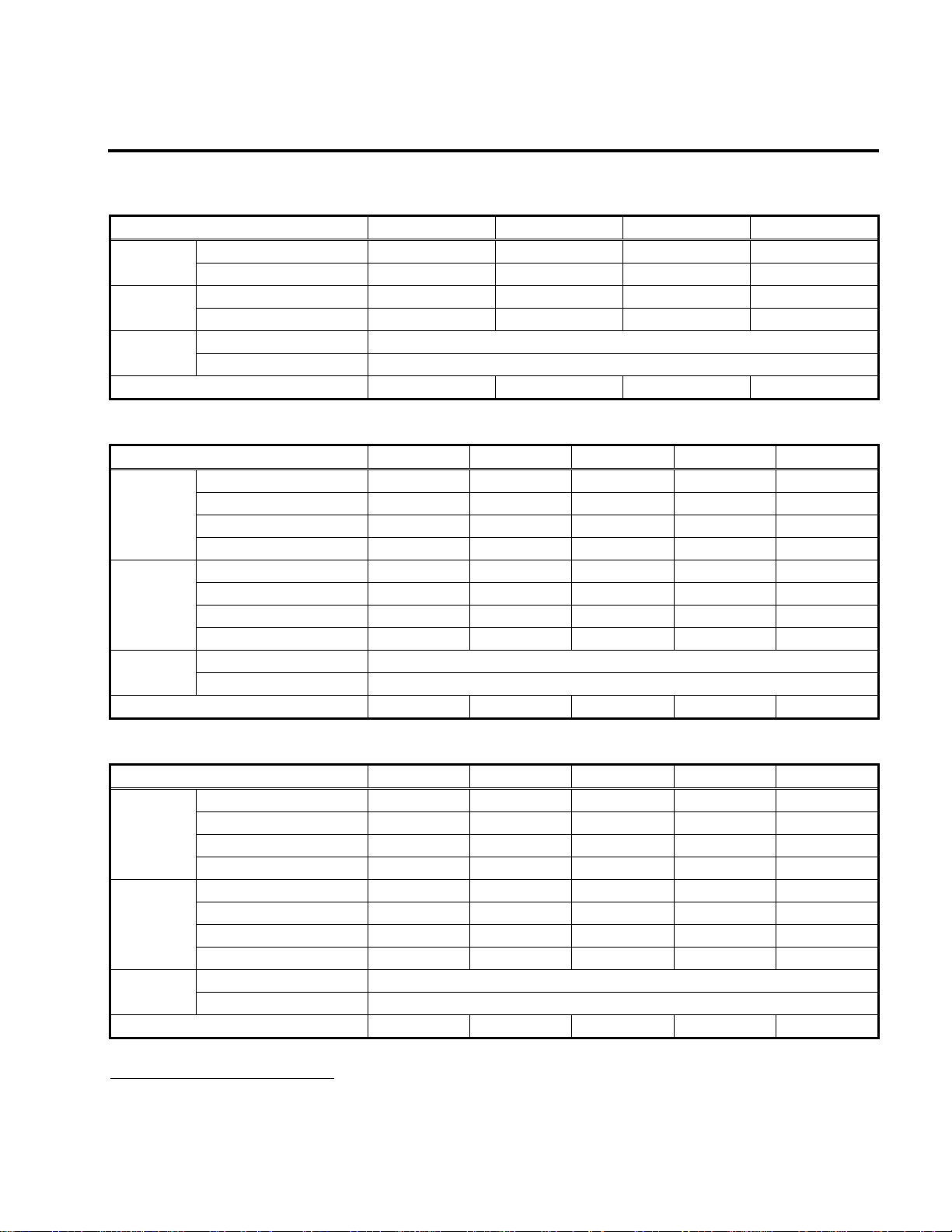
USER SELECTION GUIDE (iH SPECIFICATIONS)
200~230V Class (40 - 75HP)
Model Number SV030iH-2U SV037iH-2U SV045iH-2U SV055iH-2U
Motor
1
Rating
Output
Ratings
Input
Ratings
Weight [kg (lbs)] 42 (93) 42 (93) 56 (123) 56 (123)
380~400V Class (40 - 100HP)
Motor
1
Rating
Output
Ratings
Input
Ratings
Weight [kg (lbs)] 45 (99) 45 (99) 63 (139) 63 (139) 68 (150)
Constant Torque [HP] 40 50 60 75
Constant Torque [kW] 30 37 45 55
Constant Torque [kVA]
2
46 55 68 83
Constant Torque FLA [A] 122 146 180 220
Input Voltage 3 Phase, 200 to 230 V (± 10%)
Input Frequency 50 to 60 Hz (± 5%)
Model Number SV030iH-4U SV037iH-4U SV045iH-4U SV055iH-4U SV075iH-4U
Constant Torque [HP] 40 50 60 75 100
Constant Torque [kW] 30 37 45 55 75
Variable Torque [HP] 50 60 75 100 125
Variable Torque [kW] 37 45 55 75 90
Constant Torque FLA [A] 61 75 91 110 152
Constant Torque [kVA]
3
40 50 60 70 100
Variable Torque FLA [A] 80 96 115 125 160
Variable Torque [kVA]
3
52 62 74 80 103
Input Voltage 3 Phase, 380 to 400 V (± 10%)
Input Frequency 50 to 60 Hz (± 5%)
380~400V Class (125 - 300HP)
Model Number SV090iH-4U SV110iH-4U SV132iH-4U SV160iH-4U SV220iH-4U
Constant Torque [HP] 125 150 175 215 300
Motor
1
Rating
Output
Ratings
Input
Ratings
Weight [kg (lbs)] 98 (216) 98 (216) 122 (269) 122 (269) 175 (386)
1
Indicates the maximum applicable capacity when using a 4 Pole motor.
2
Rated kVA (v3*V*I) is based on 220V.
3
Rated kVA (v3*V*I) is based on 380V.
Constant Torque [kW] 90 110 132 160 220
Variable Torque [HP] 150 175 215 250 350
Variable Torque [kW] 110 132 160 185 280
Constant Torque FLA [A] 183 223 264 325 432
Constant Torque [kVA]
3
120 145 170 200 280
Variable Torque FLA [A] 228 264 330 361 477
Variable Torque [kVA]
3
147 170 213 233 307
Input Voltage 3 Phase, 380 to 400 V (± 10%)
Input Frequency 50 to 60 Hz (± 5%)
3
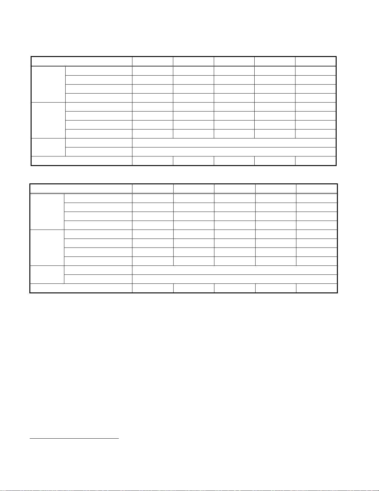
440~460V Class (40 - 100HP)
Model Number SV030iH-4U SV037iH-4U SV045iH-4U SV055iH-4U SV075iH-4U
Constant Torque [HP] 40 50 60 75 100
Motor
Rating
4
Constant Torque [kW] 30 37 45 55 75
Variable Torque [HP] 50 60 75 100 125
Variable Torque [kW] 37 45 55 75 90
Constant Torque FLA [A] 61 75 91 110 152
Output
Ratings
Input
Ratings
Constant Torque [kVA]
Variable Torque FLA [A] 80 96 115 125 160
Variable Torque [kVA]
Input Voltage 3 Phase, 440 to 460 V (± 10%)
Input Frequency 50 to 60 Hz (± 5%)
5
5
45 56 68 82 113
60 70 86 93 120
Weight [kg (lbs)] 45 (99) 45 (99) 63 (139) 63 (139) 68 (150)
440~460V Class (125 - 300HP)
Model Number SV090iH-4U SV110iH-4U SV132iH-4U SV160iH-4U SV220iH-4U
Constant Torque [HP] 125 150 200 250 300
Motor
4
Rating
Output
Ratings
Input
Ratings
Weight [kg (lbs)] 98 (216) 98 (216) 122 (269) 122 (269) 175 (386)
Constant Torque [kW] 90 110 132 160 220
Variable Torque [HP] 150 200 250 300 350
Variable Torque [kW] 110 132 185 220 280
Constant Torque FLA [A] 183 223 264 325 432
Constant Torque [kVA]
5
136 166 197 242 322
Variable Torque FLA [A] 228 264 330 361 477
Variable Torque [kVA]
5
170 200 246 270 356
Input Voltage 3 Phase, 440 to 460 V (± 10%)
Input Frequency 50 to 60 Hz (± 5%)
4
Indicates the maximum applicable capacity when using a 4 Pole motor.
5
Rated kVA (v3*V*I) is based on 440V.
4

All Models
Output Ratings
Control
Operating
Programmable
I/O
Protective
Functions
Operating
Conditions
Enclosure IP00
Inter National Standards CE Certified, UL Listed (UL508C)
Max. Frequency 0.5 to 400 Hz
Output Voltage 3 Phase, 0 to Input Voltage
Control Method Space Vector PWM
Frequency Setting
Resolution
Frequency Accuracy
Digital Reference: 0.01 Hz (Below 100Hz), 0.1 Hz (Over 100Hz)
Analog Reference: 0.03 Hz / 60Hz
Digital: 0.01% of Maximum Output Frequency
Analog: 0.1% of Maximum Output Frequency
V/F Ratio Linear, Non-Linear, User Programmable
Braking Torque (w/o DB) About 20%
Overload Capacity CT 150% of Rated Current for 1 Minute, 200% for 0.5 Second
Overload Capacity VT 110% of Rated Current for 1 Minute, 150% for 0.5 Second
Torque Boost Manual Torque Boost (0 to 20%), Auto Torque Boost
Operation Method Keypad / Terminal / Remote (Optional)
Frequency Setting Analog: 0 to 10 V / 4 to 20mA, Digital: Keypad
Accel / Decel Time 0.1 to 6,000 sec, 8 Pre-Defined (Programmable)
Multi-Step 8 Preset Operational Speed
Jog Jog Operation
Operating Function
Operating Status
DC Braking, Frequency Limit, Frequency Jump, Slip Compensation, PI Control, Stall
Prevention
Frequency Detection Level, Overload Alarm, Stalling, Over Voltage, Under Voltage,
Inverter Overheat, Run, Stop, Constant Speed, Speed Searching
Start Signal Forward, Reverse
Programmable Input 6 Programmable Inputs
5 Programmable Outputs: 2 Form A Contact (N.O.)
Programmable Output
Fault Contact Output (A, C, B) – 250VAC 1A, 30VDC 1A
3 Open Collector Outputs: 24V, 50mA
Analog 4 ~ 20mA
Meter RPM, Hz, Current, Voltage (Output Pulse: 500Hz, Output Voltage: 0 ~ 10V)
Inverter Trip
Over Voltage, Under Voltage, Over Current, Inverter Overload, Fuse Open, Ground
Fault, Inverter Overheat, Motor Overheat, Main CPU Error.
Stall Prevention Over Current Prevention
Instant Power Loss
Less Than 15msec: Continuous Operation
More Than 15msec: Auto Restart (Programmable)
Ambient Temp. 14 °F ~ 104 °F (-10 °C ~ 40 °C), CE Certification: 41 °F ~ 104 °F (5 °C ~ 40 °C)
Storage Temp. -4 °F ~ 149 °F (-20 °C ~ 65 °C)
Humidity 90% RH Max. (Non-Condensing), CE Certification: 5 ~85% (Non-Condensing)
Altitude / Vibration Below 3,300ft (1,000m) / Below 5.9m/sec2 (0.6g)
Air Pressure 86 ~ 106kPa
Application Site No Corrosive Gas, Combustible Gas, Oil Mist, or Dust
Cooling Method Forced Air Cooling
6
6
UL is available only for 380~460V Class inverters.
5
CHAPTER 1 - INSTALLATION
AAB
B
1.1 Inspection
ü Inspect the inverter for any damage that may have occurred during shipping.
ü Check the nameplate on the inverter. Verify the inverter unit is the correct one for the application. The
numbering system for the inverter is as shown below.
037SV iH 4U (380V)
LG Inverter Motor Capacity Series Name Input Voltage 380V Input
2 : 200 ~ 230V (±10%) (50/60Hz)
4 : 380 ~ 460V (±10%) (50/60Hz)
1.2 Environmental Conditions
ü Verify ambient condition for the mounting location.
- Ambient temperature should not be below 14ºF (-10ºC) or exceed 104ºF (40ºC).
- Relative humidity should be less than 90% (non-condensing).
- Altitude should be below 3,300ft (1,000m).
ü Do not mount the inverter in direct sunlight and isolate it from excessive vibration.
ü If the inverter is going to be installed in an environment with high probability of penetration of dust, it
must be located inside watertight electrical boxes, in order to get the suitable IP degree.
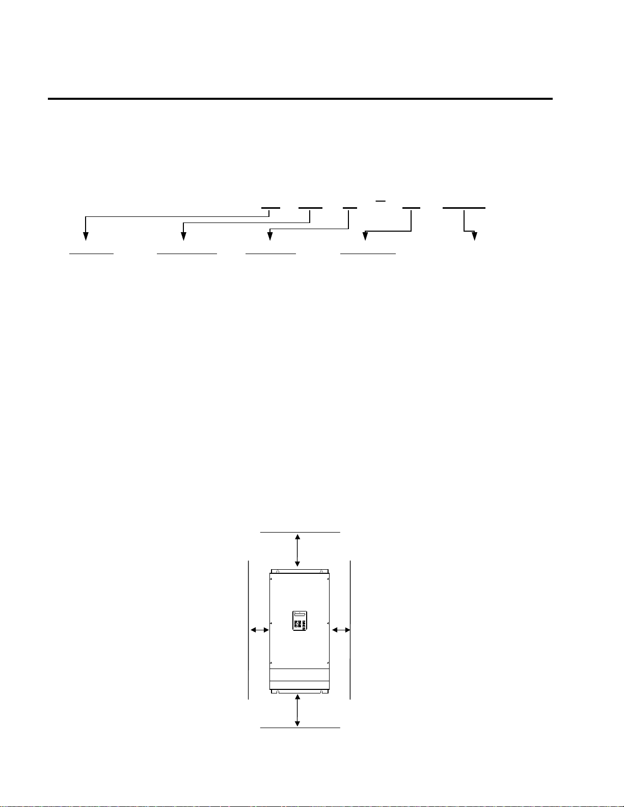
1.3 Mounting
ü The inverter must be mounted vertically with sufficient horizontal and vertical space between adjacent
equipment (A= Over 6" (150mm), B= Over 2" (50mm)).
6
Chapter 1 - Installation
1.4 Other Precautions
ü Do not carry the inverter by the front cover.
ü Do not install the inverter in a location where excessive vibration is present. Be cautious when installing on
presses or moving equipment.
ü The life span of the inverter is greatly affected by the ambient temperature. Install in a location where
temperature are within permissible limits (- 10 ~ 40 ? ).
ü The inverter operates at high-temperatures - install on a non-combustible surface.
ü Do not install the inverter in high-temperature or high-humidity locations.
ü Do not install the inverter in a location where oil mist, combustible gas, or dust is present. Install the
inverter in a clean location or in an enclosed panel, free of foreign substance.
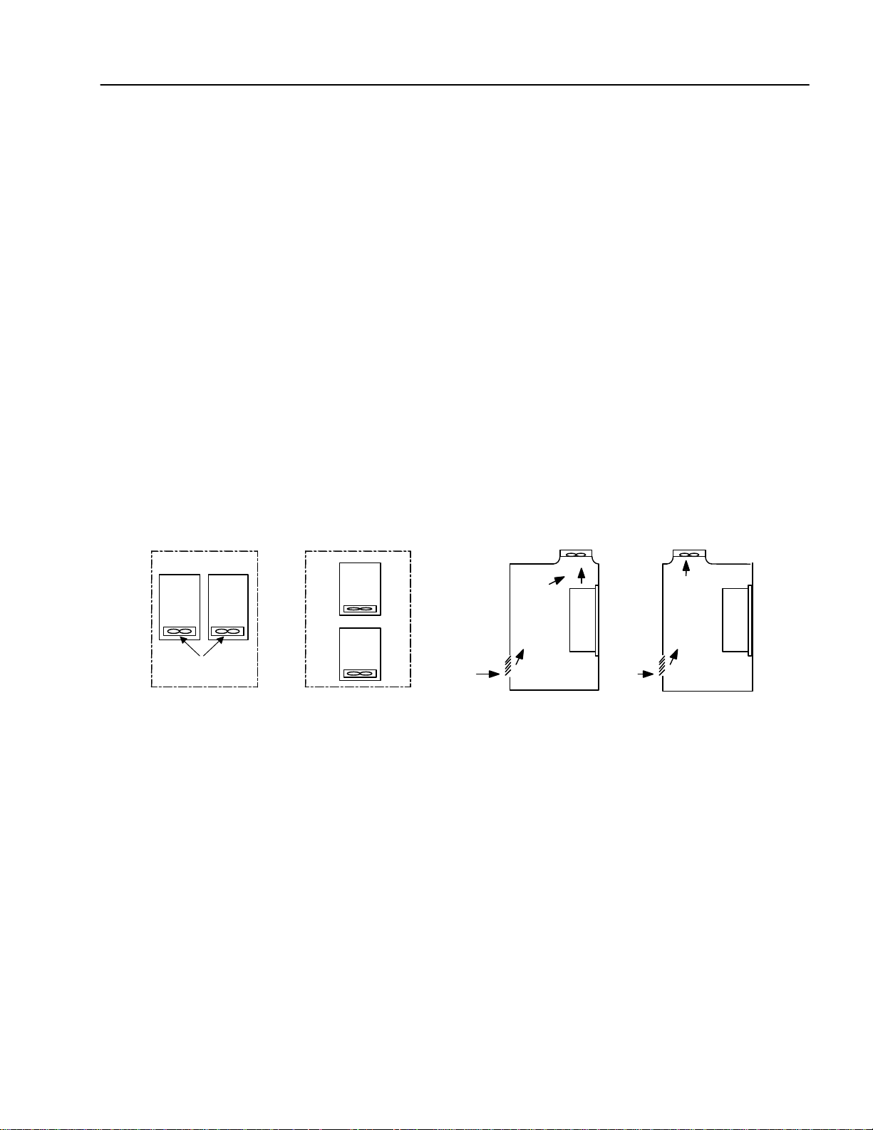
ü When installing the inverter inside a panel with multiple inverters or a ventilation fan, use caution.
If installed incorrectly, the ambient temperature may exceed specified limits.
Panel Panel
Inverter
Inverter
Inverter
Cooling fan
GOOD (O)
Inverter
BAD (X)
[When installing several inverters in a panel]
Ventilating fan
GOOD (O)
[When installing a ventilating fan in a panel]
ü Install the inverter using screws or bolts to insure the inverter is firmly fastened.
BAD (X)
7

Chapter 1 - Installation
1.5 Dimensions
1.5.1 200V ~ 230V Class
SV030iH-2U
SV037iH-2U
Unit: mm (inch)
VARIABLE FREQUENCY DRIVE
SV045iH-2U
SV055iH-2U
VARIABLE FREQUENCY DRIVE
8
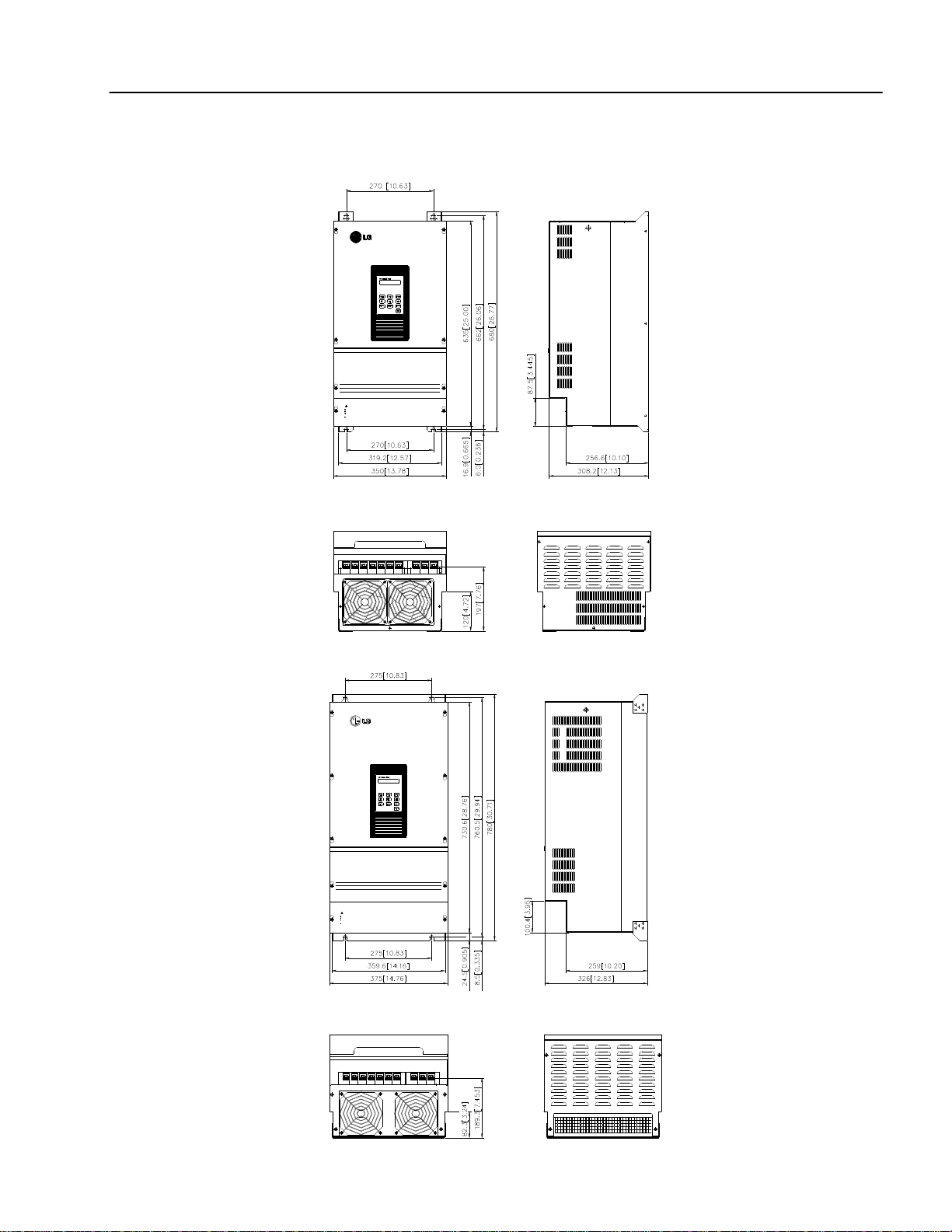
1.5.2 380V ~ 460V Class
SV030iH-4U
SV037iH-4U
VARIABLE FREQUENCY DRIVE
STARVERT-IH
STARVERT-iH
CAUTION
Read the manual and follow the safety instructions before installation or operation.
Do not connect the power supply to the drive output terminals (U,V,W).
Before opening the cover, disconnect all power and wait at least 3 minutes until DC
bus capacitors discharge.
"Risk of Electric Shock" More than one disconnect switch is required to
-
de energize the equipment before servicing.
-
Chapter 1 - Installation
SV045iH-4U
SV055iH-4U
SV075iH-4U
VARIABLE FREQUENCY DRIVE
STARVERT-IH
STARVERT-iH
CAUTION
Read the manual and follow the safety instructions before installation or operation.
Do not connect the power supply to the drive output terminals (U,V,W).
Before opening the cover, disconnect all power and wait at least 3 minutes until DC
bus capacitors discharge.
-"Risk of Electric Shock" More than one disconnect switch is required to
de energize the equipment before servicing.
-
9
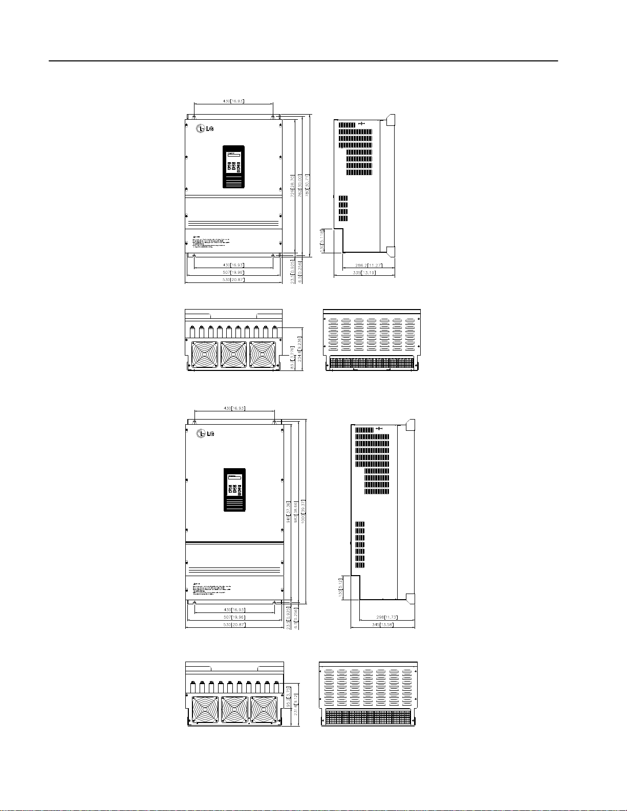
Chapter 1 - Installation
STARVERT-IH
SV090iH-4U
SV110iH-4U
VARIABLE FREQUENCY DRIVE
STARVERT-IH
STARVERT-iH
SV132iH-4U
SV160iH-4U
VARIABLE FREQUENCY DRIVE
STARVERT-iH
10
STARVERT-IH
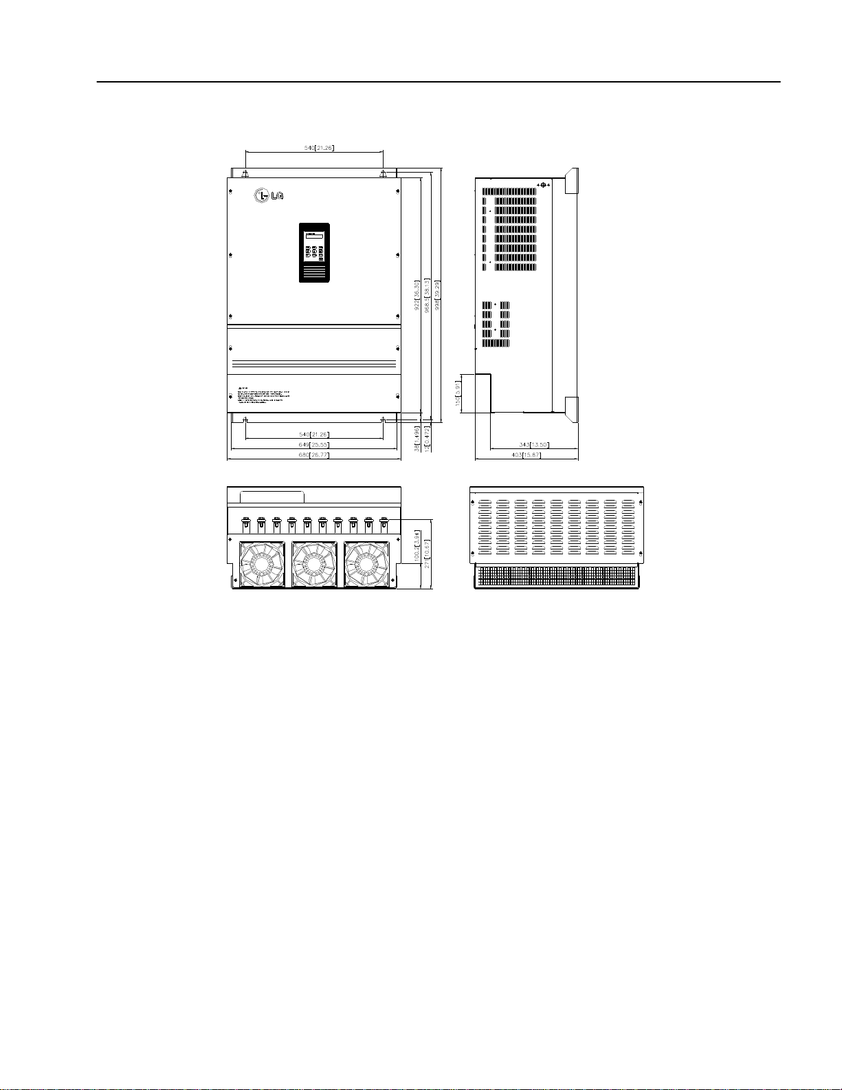
SV132iH-4U
SV160iH-4U
Chapter 1 - Installation
VARIABLE FREQUENCY DRIVE
STARVERT-iH
11
Chapter 1 - Installation
2
50/60 Hz
RX BX
P1 P3 P4 P5 P6 CM EG VR V1 I CM LM + + FM CM LM A B C 1A 1B
EG P2
2B IO CM
supply for
P1
3
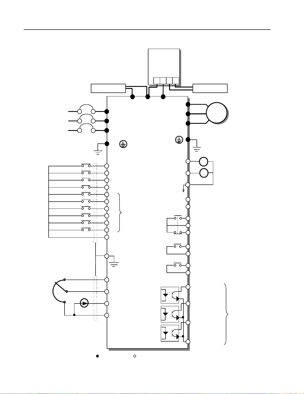
1.6 Basic Wiring
DC Bus Choke (Optional)
DC Bus Choke
Dynamic
Braking Unit
(Optional)
DB Unit(Optional)
DB Resitor
P N B1 B2
DB Resistor
MCCB(OPTION)
φ
3
30/460 V
Forward Run/Stop
Reverse Run/Stop
Inverter Disable
Fault Reset
Multi-function Input 1
Multi-function Input 2
Multi-function Input 3
Multi-function Input 4
Multi-function Input 5
Multi-function Input 6
Common Terminal
Potentiometer
(10 kohm, 1/2W)
Speed signal Input
P2
R
S
N
U
V
W
MOTOR
T
G( )
G( )
Output Frequency Meter
FM
FX
(NO)
(NC)
OC1
OC2
Common for
FM,LM
2A
Analog output
(4 ~ 20mA)
Fault output relay
lless than AC250V, 1A
lless than DC30V, 1A
Multi-function output relay1
lless than AC250V, 1A
lless than DC30V, 1A
Factory setting: ‘COMM’
Multi-function output relay2
lless than AC250V, 1A
lless than DC30V, 1A
Factory setting: ‘COMM’
Multi-function output 1
Factory setting: ‘STEP_L’
Multi-function output 2
Factory setting: ‘STEP_M’
Multi-function output 3
Factory setting: ‘STEP_H’
RST
Factory Setting:
Multi-speed and
Muti-acc/dec time
Shielded sheath
connection
Power
speed signal:
+ 11V, 10mA
Speed signal input:
0 ~ 10V
Speed signal input:
4 ~20mA (250ohm)
Common for
*2
VR, V1, I
(0~10V pulse)
Output Voltage/Current
Meter(0~10V pulse)
Open
Collector
24V, 50mA
OC3
Note) Main Circuit Terminals Control Circuit Terminals.
1. Analog speed command may be set by Voltage, Current or both..
2. When installing the DC Reactor, the Common Busbar between P1 and P2 must be removed.
12
Common for
Multi-function outputs
Chapter 1 - Installation
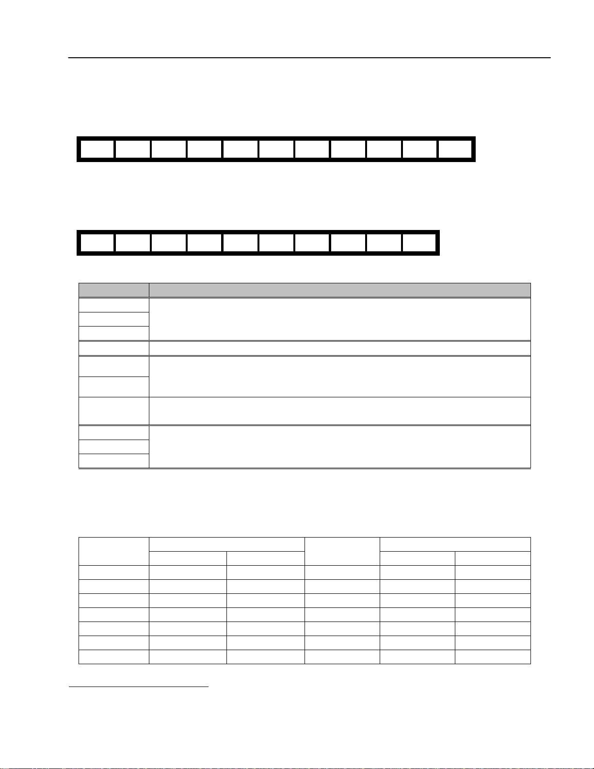
1.7 Power Terminals
n Type A Configuration: 230V Class (SV030iH-2U, SV037iH-2U, SV045iH-2U, SV055iH-2U)
R S T G U V W G P1 P2 N
n Type B Configuration: 380 ~ 460V Class (SV030iH-4U, SV037iH-4U, SV045iH-4U, SV055iH-4U,
SV075iH-4U, SV090iH-4U, SV110iH-4U, SV132iH-4U, SV160iH-4U, SV220iH-4U)
R S T G U V W P1 P2 N
Symbols Functions
R
S
T
G
AC Line Voltage Input
(3 Phase, 200 ~ 230VAC or 380 ~ 460VAC)
Earth Ground
P1
P2
N
U
V
W
“Suitable for use on a circuit capable of delivering not more than 10,000 rms symmetrical amperes,
240 volts maximum for 230V class models and 480 volts maximum for 460V class models.”
Positive DC Bus Terminal
External DC Reactor (P1-P2) and DB Unit (P2-P1) Connection Terminals
Negative DC Bus Terminal
DB Unit (N-N2) Connection Terminal
3-Phase Power Output Terminals to Motor
(3 Phase, 200 ~ 230VAC or 380 ~ 460VAC)
1.7.1 Power Wiring Size
Terminals (R, S, T, U, V, W) Terminals (R, S, T, U, V, W)Model Number
Wire Size (mm2) Wire Size (AWG)
SV030iH-2U 60 1/0 SV055iH-4U 38 2
SV037iH-2U 60 1/0 SV075iH-4U 60 1/0
SV045iH-2U 100 4/0 SV090iH-4U 60 1/0
SV055iH-2U 100 4/0 SV110iH-4U 80 3/0
SV030iH-4U 22 4 SV132iH-4U 100 4/0
SV037iH-4U 22 4 SV160iH-4U 100 4/0
SV045iH-4U 38 2 SV220iH-4U 100 * 2 4/0 * 2
Model Number
Wire Size (mm2) Wire Size (AWG)
1
This P terminal is provided on optional Dynamic Braking Unit. (Refer to DB Unit Manual for detail terminal configuration)
2
This N terminal is provided on optional Dynamic Braking Unit. (Refer to DB Unit Manual for detail terminal configuration)
13
Chapter 1 - Installation
!
!
3 Phase
Refer to DB Unit Manual for
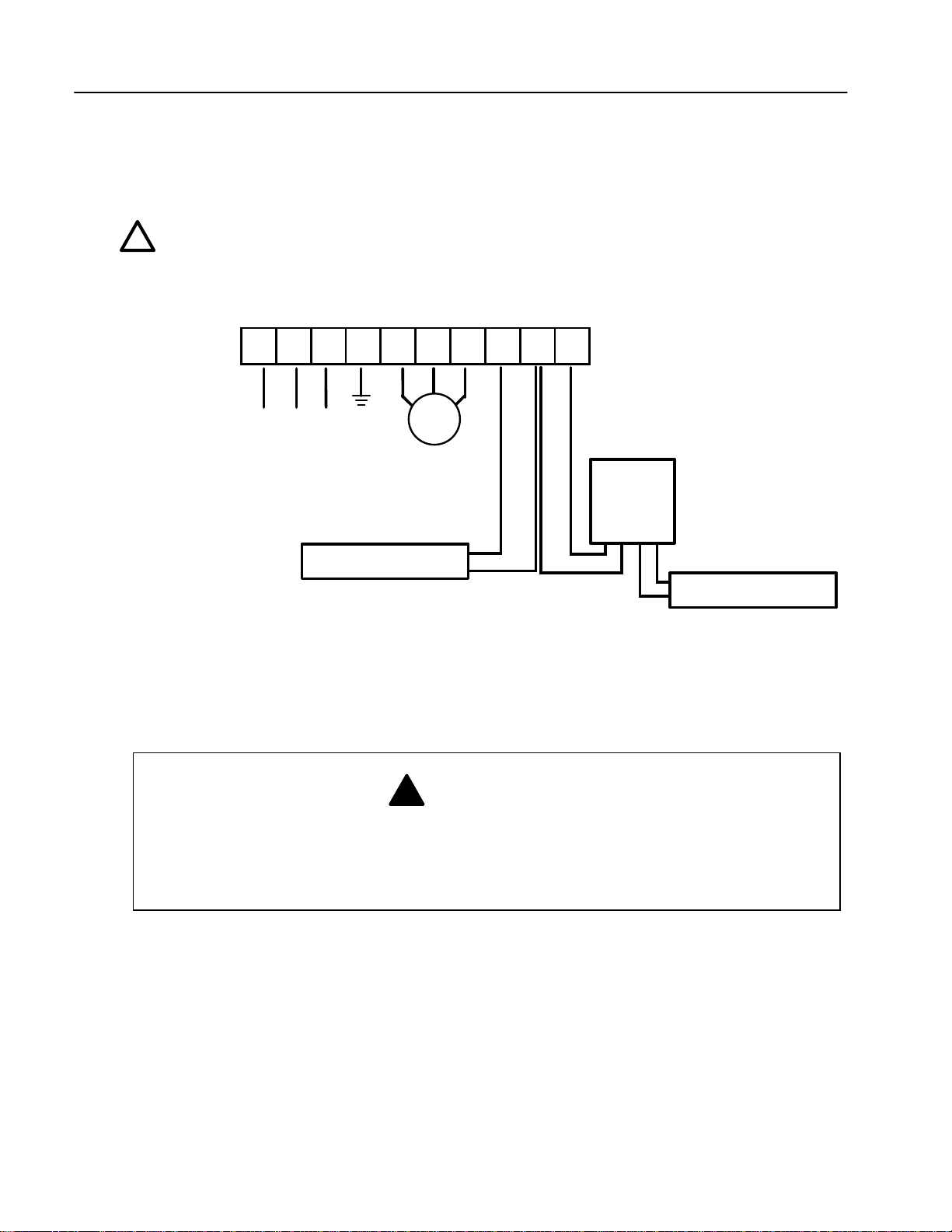
1.7.2 Terminal Configuration
A Dynamic Braking Unit or a DC Bus Choke or both of them may be added to iH series inverters.
Jumper Between P1 and P2 Must Be Removed In Order
To Install a DC Bus Choke.
R S T G U V W P1 P2 N
Motor
Power Input
Dynamic
Braking
Unit
DC Bus Choke
Fig. 1 – Type C Dynamic Braking Unit, DC Bus Choke Installation
detailed terminal configuration
Dynamic Braking Resistor
WARNING
Normal stray capacitance between the inverter chassis and the power devices inside the
inverter and AC line can provide a high impedance shock hazard. Refrain from applying
power to the inverter if the inverter frame (Power terminal G) is not grounded.
14
Chapter 1 - Installation
!!!
!
1.7.3 Wiring Power Terminals
n Wiring Precautions
ü The internal circuits of the inverter will be damaged if the incoming power is connected and applied to
output terminals (U, V, W).
ü Use ring terminals with insulated caps when wiring the input power and motor wiring.
ü Do not leave wire fragments inside the inverter. Wire fragments can cause faults, breakdowns, and
malfunctions.
ü For input and output, use wires with sufficient size to ensure voltage drop of less than 2%.
Motor torque may drop of operating at low frequencies and a long wire run between inverter and motor.
ü Do not use a 3-wire cable for long distances. Due to increased leakage capacitance between wires, over-
current protective feature may operate or equipment connected to the output side may malfunction.
ü Never short between B1 and B2 terminals of the inverter.
ü The main circuit of the inverter contains high frequency noise, and can hinder communication equipment
near the inverter. To reduce noise, install line noise filters on the input side of the inverter.
ü Do not use power factor capacitor, surge killers, or RFI filters on the output side of the inverter. Doing so
may damage these components.
ü Always check whether the LCD and the charge lamp for the power terminal are OFF before wiring
terminals. The charge capacitor may hold high-voltage even after the power is disconnected. Use caution
to prevent the possibility of personal injury.
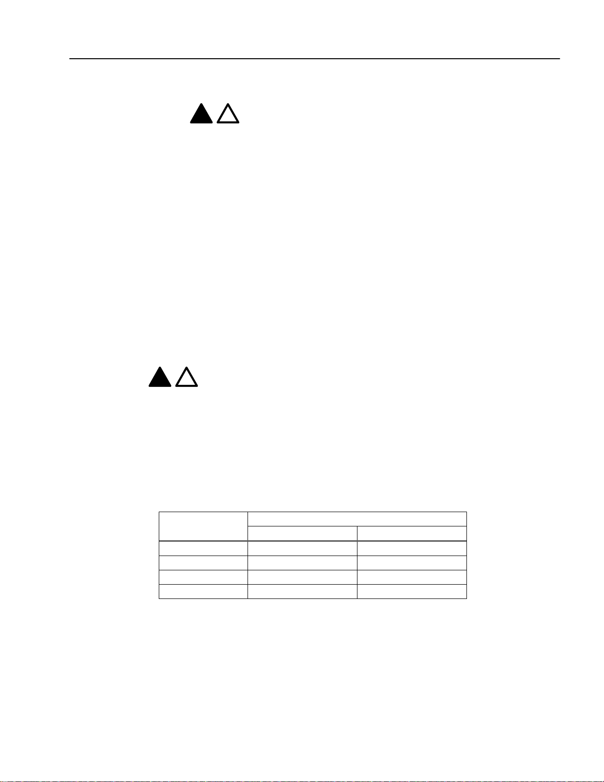
n Grounding
ü The inverter is a high switching device, and leakage current may flow. Ground the inverter to avoid
electrical shock. Use caution to prevent the possibility of personal injury.
ü Connect only to the dedicated ground terminal of the inverter. Do not use the case or the chassis screw for
grounding.
ü The protective earth conductor must be the first one in being connected and the last one in being
disconnected.
ü Grounding wire should be at least the size listed in the following table and be as short as possible.
Motor Capacity
30 ~ 37kW 4 (22) 6 (14)
45 ~ 75kW 2 (38) 4 (22)
90 ~ 132kW - 2 (38)
160 ~ 280kW - 1/0 (60)
Grounding wire dimensions, AWG (mm²)
200V Class 400VClass
15
Chapter 1 - Installation
3 Phase
!
!
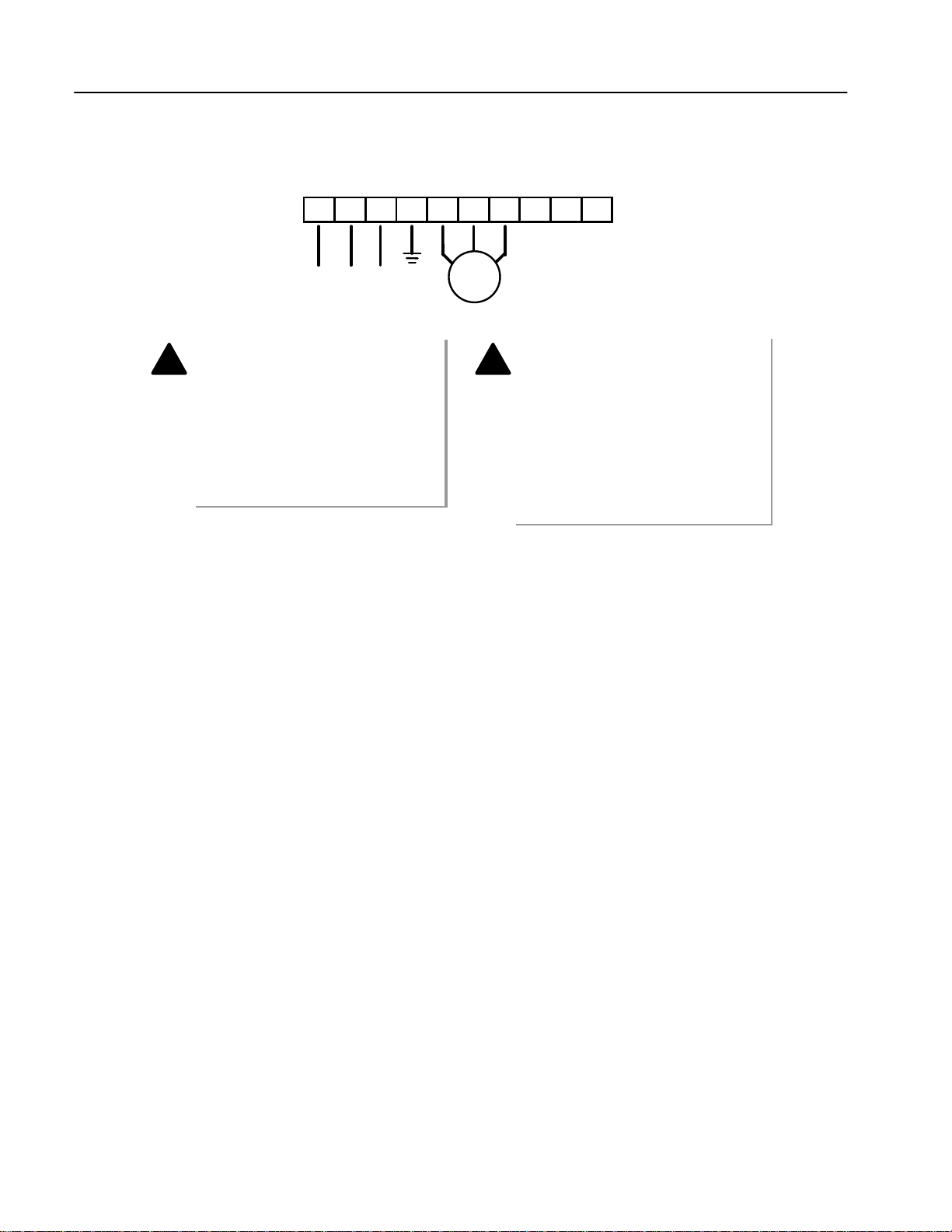
n Power and Motor Connection
Power Input
R S T G U V W P1 P2 N
Motor
Power supply must be connected
to the R, S, and T terminals.
Connecting it to the U, V, and W
terminals causes internal damages
to the inverter. Arranging the phase
sequence is not necessary.
Motor should be connected to the
U, V, and W terminals.
If the forward command (FX) is on,
the motor should rotate counter
clockwise when viewed from the load
side of the motor. If the motor rotates
in the reverse, switch the U and V
terminals.
16
1.8 Control Terminals
!
1A 1B 2A 2B OC1 OC2 EG RST FX RX BX CM VR V1 V2 IO
A C B OC3 CM P1 P2 P3 P4 P5 P6 CM I FM LM CM
Type Symbol Name Description
P1 ~ P6
Starting Contact Function Select
Input signal
Analog Frequency Setting
Pulse
Analog
A, C, B Fault Output Relay
Output signal
Contact
CO1, OC2,
FX Forward Run Command Forward Run When Closed and Stopped When Open.
RX Reverse Run Command Reverse Run When Closed and Stopped When Open.
BX Emergency Stop
RST Fault Reset Used for Fault Reset.
CM Sequence Common Common Terminal for Contact Inputs.
VR
V1
V2
I
CM
FM
LM
IO
1A-1B,
2A-2B
OC3
EG
Multi-Function input
1 ~ 6
Frequency Setting Power
(+10V)
Frequency Reference
(Voltage)
Frequency Reference
(Current)
Frequency Setting Common
Terminal
Frequency Output
(For External Monitoring)
Current/Voltage Output
(For External Monitoring)
Frequency Output
(4 ~ 2-mA)
Multi-Function Output Relay 1
and 2 (AUX1, AUX2)
Multi-Function Open Collector
Output
Multi0Function Open Collector
Output Common Terminal
Used for Multi-Function Input Terminal.
When the BX Signal is ON the Output of the Inverter is Turned Off. When
Motor uses an Electrical Brake to Stop, BX is used to Turn Off the Output
Signal. When BX Signal is OFF (Not Turned Off by Latching) and FX Signal
(or RX Signal) is ON, Motor continues to Run.
Used as Power for Analog Frequency Setting. Maximum Output is +12V,
10mA.
Used for 0-10V Input Frequency Reference. Input Resistance is 20 KO
Used for 4-20mA Input Frequency Reference. Input Resistance is 250 O
Common Terminal for Analog Frequency Setting
Outputs PWM signal according to inverter Output Frequency. Maximum
Output Voltage and Output Current are 0-12V and 1mA.
Outputs One of the Following: Output Current, Output Voltage. Default is set
to Output Voltage. Maximum Output Voltage and Output Current are 0-12V
and 1mA. Output Frequency is Set at 1.8kHz.
Outputs Analog Signal according to inverter Output Frequency.
Activates when Protective Function is Operating. AC250V, 1A or less;
DC30V, 1A or less.
Fault: 30A-30C Closed (30B-30C Open)
Normal: 30B-30C Closed (30A-30C Open)
Use after Defining Multi-Function Output Terminal. AC250V, 1A or less;
DC30V, 1A or less.
Use after Defining Multi-Function Output Terminal. DC24V, 50mA
Ground Terminal for OC1, OC2, OC3.
Chapter 1 - Installation
17
Chapter 1 - Installation
!
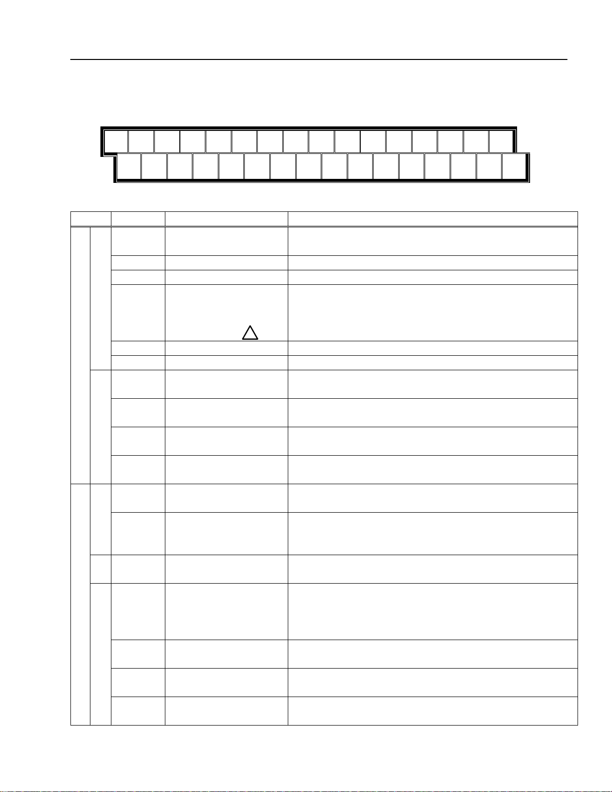
1.8.1 Wiring Control Terminals
n Wiring Precautions
ü CM and EG terminals are insulated to each other. Do not connect these terminals with each other and do
not connect these terminals to the power ground.
ü Use shielded wires or twisted wires for control circuit wiring, and separate these wires from the main
power circuits and other high voltage circuits.
ü Use 1.25mm²(22AWG) stranded cables for control terminal connection.
n Control Circuit Terminal
The control input terminal of the control circuit is ON when the circuit is configured to the current flows out of
the terminal, as shown in the following illustration. CM terminal is the common terminal for the contact input
signals.
Resistor
Current
External Sequence
24 VDC
FX
Resistor
RX
CM
Inverter Circuitry
CAUTION
Do not apply voltage to any control input terminals (FX, RX, P1~P3, BX, RST, FM, LM, IO, CM
Etc).
18

CHAPTER 2 - OPERATION
The iH series inverter has three parameter groups separated according to their function, as indicated in the
following table.
2.1 Parameter Groups
LCD Keypad
Group
Drive Group DRV
Function Group FUN
Input/Output
Group
Refer to the function descriptions in Chapter 5 for detailed description of each group.
(Upper Left
Corner)
I/O
Description
Command Frequency, Accel/Decel Time Etc.
Basic Parameters
Maximum Frequency, Amount of Torque Boost, Etc.
Basic Related Parameters
Multi-Function Terminal Settings.
Parameters Needed for Sequence Operation
19
Chapter 2 - Operation
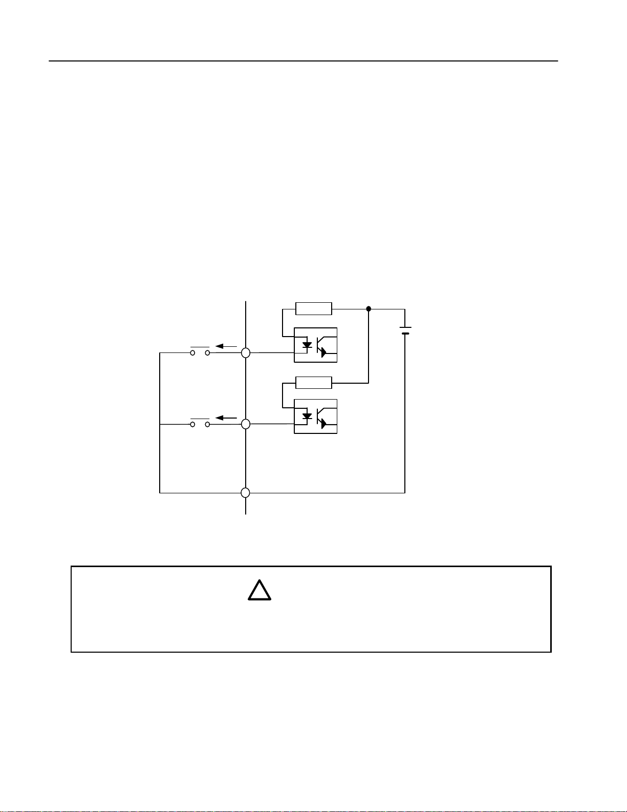
32 Character, back lit,
The
Mode Button
moves
The
Up and Down
The
Reverse Run
The
Program Button
is
change data.
The
Enter Button
is
This button is used to
The
Forward Run
The
Stop Button
blinks
The
Reset Button
is
Otherwise display command frequency
2.2 Display
The LCD keypad can display up to 32 alphanumeric characters. Various settings can be checked directly from
the display. The keypad is fully upload and download capable. The following is an illustration of the keypad
used to go into
programming mode to
LCD display. The
backlight is adjustable.
used to enter changed
data within a parameter.
through the three
program groups: DRV,
FUN and I/O
move cursor across
display in programming
mode.
Arrows are used to
move through and
change data.
Button blinks when the
drive Accels or Decels.
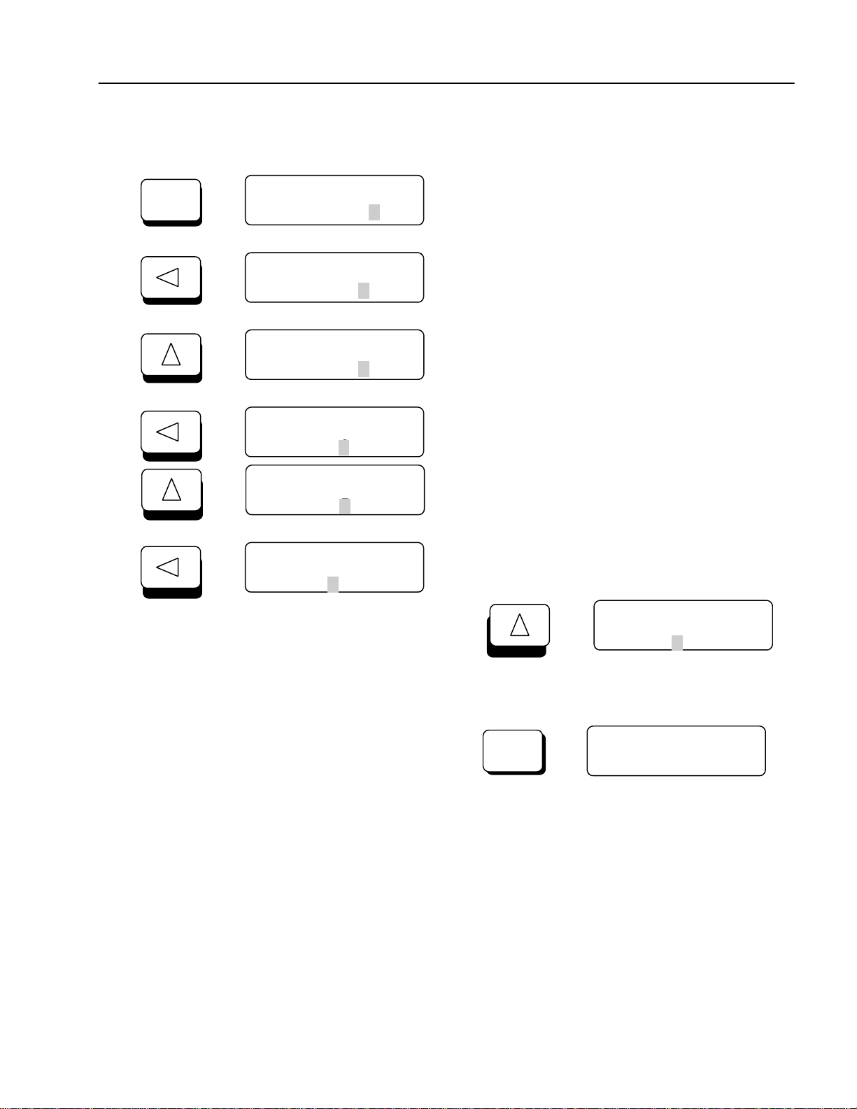
2.3 Alpha-numerical Display
Manual mode is selected
Parameter group
Button blinks when the
drive Accels or Decels.
when there is a fault.
used to reset Faults.
Run/Stop method selection
Source of reference frequency
DRV¢º Manual K/K
00 FWD 60.00 Hz
Parameter code
Direction of rotation
Drive output frequency during run,
20
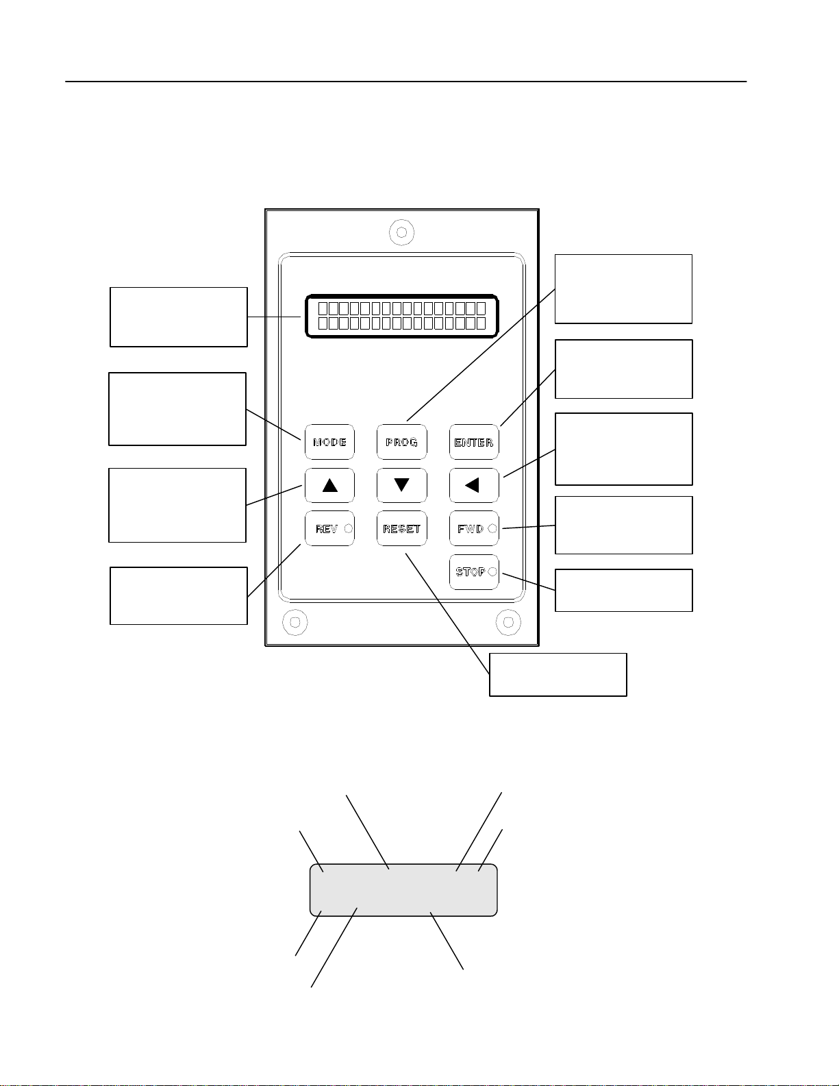
2.4 Procedure of Setting Data
To change command frequency from 30.00Hz to 45.50Hz:
Chapter 2 - Operation
PROG
DRV¢º Manual K/K
00 REV 30.00 Hz
0
DRV¢º Manual K/K
00 REV 30.00 Hz
0
DRV¢º Manual K/K
00 REV 30.50 Hz
5
DRV¢º Manual K/K
00 REV 30.50 Hz
0
DRV¢º Manual K/K
00 REV 35.50 Hz
5
DRV¢º Manual K/K
00 REV 35.50 Hz
3
Press PROG key and the cursor appears on the lowest
digit.
Press LEFT key once to move digit.
Press UP key 5 times.
Press SHIFT key once to shift the cursor to next digit.
Press UP key 5 times.
Press SHIFT key once to shift the cursor to next digit.
Press UP key once to make 4.
Press ENTER key to store new value.
ENTER
The same procedure is applied to all other parameters. While the drive is running, the output frequency can be
changed to a new command frequency.
? Note: Some parameters cannot be changed while the inverter is running (refer to the function table in Chapter 4)
DRV¢º Manual K/K
00 REV 45.50 Hz
4
DRV¢º Manual K/K
00 REV 45.50 Hz
21
Chapter 2 - Operation
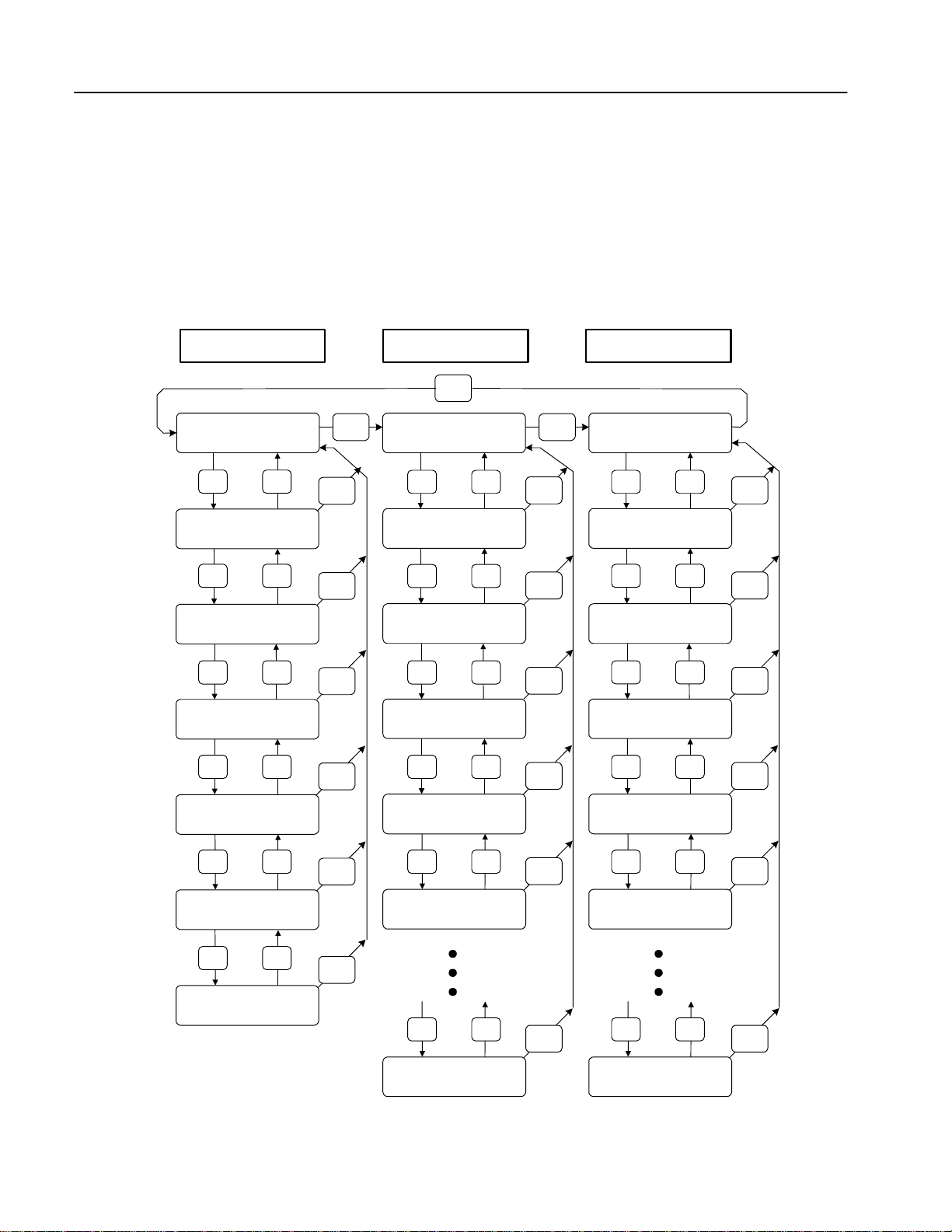
2.5 Parameter Navigation
In any of the parameter groups, users may jump to a specific parameter code by following these steps:
n Select a parameter group that requires a change.
n At the beginning of each program group the menu will read [Jump Code]. Press the [PROG] key. Enter the
code number of the parameter needing to be changed, then press [ENTER] key. There is no jump code for
[Drive Group].
Drive Group Function Group I/O Group
MODE
DRV¢º Manual K/K
00 FWD 60.00 Hz
? ?
DRV¢º Acc. time
01 30.0 sec
? ?
DRV¢º Dec. time
02 30.0 sec
? ?
DRV¢º Current
03 x.x A
? ?
DRV¢º Speed
04 xxxrpm
? ?
MODE MODE
MODE
MODE
MODE
MODE
MODE
FUN¢º Jump Code
00 41
? ? ? ?
FUN¢º Freq. set
01 Key
? ?
FUN¢ºRun/stop set
02 Key
? ?
FUN¢ºRun prohibit
03 None
? ?
FUN¢º Freq. max
04 60.00 Hz
? ?
MODE
MODE
MODE
MODE
MODE
I/O¢º Jump Code
00 1
I/O¢º P1 input
01 SPD_L
? ?
I/O¢º P2 input
02 SPD_M
? ?
I/O¢º P3 input
03 SPD_H
? ?
I/O¢º P4 input
04 ACCT_L
? ?
MODE
MODE
MODE
MODE
MODE
DRV¢º Power
05 57.5kW
? ?
DRV¢º Fault
06 No fault
MODE
FUN¢º Freq. base
05 60.00 Hz
? ?
FUN¢º Para. lock
98 0
22
MODE
I/O¢º P5 input
5 ACCT_M
? ?
I/O¢º FN: St.ID
61 1
MODE

Chapter 2 - Operation
2.6 Operation Method
The iH has several operation methods as shown below.
Operation Method Function Function Setting
Operation using keypad Run/Stop command and frequency are set only through
the keypad.
Operation using Control
Terminals
Operation using both
Keypad and Control
Terminals
Closing FX or RX terminal performs Run/Stop.
Frequency reference is set through V1 or I terminal.
Run/Stop is performed by the keypad.
Frequency reference is set through the V1 or I terminal.
Closing FX or RX terminal performs Run/Stop.
Frequency reference is set through the keypad.
Option
Operation using RS485 communication between
inverter and computer.
Operation using ModBus RTU communication between
inverter and PLC.
Operation using FNet communication between inverter
and computer.
FUN 01: Key
FUN 02: Key
FUN 01: Terminal
FUN 02: Terminal-1 or
Terminal-2
FUN 01: Terminal
FUN 02: Key
FUN 01: Key
FUN 02: Terminal-1 or
Terminal-2
FUN 01: Remote
FUN 02: Remote
I/O 48: RS485
FUN 01: Remote
FUN 02: Remote
I/O 48: ModBus RTU
FUN 01: Remote
FUN 02: Remote
I/O 48: FNet
23

Chapter 2 - Operation
Blank Page
24

CHAPTER 3 - QUICK- START PROCEDURES
These Quick-Start Up instructions are for those applications where:
l The user wants to get the iH inverter started quickly
l The factory-preset values are suitable for the user application
The factory-preset values are shown on the ‘Chapter 4 - Parameter List’. The iH inverter is configured to
operate a motor at 60Hz (base frequency). If the application requires coordinated control with other controllers,
it is recommended the user become familiar with all parameters and features of the inverter before applying AC
power.
1. Mounting the inverter (mount the inverter as described in ‘1.3 Mounting’)
l Install in a clean, dry location
l Allow a sufficient clearance around top and sides of inverter
l The ambient temperature should not exceed 40°C (104°F)
l If two or more inverters are installed in an enclosure, add additional cooling
2. Wiring the inverter (connect wiring as described in ‘1.7 Power Terminals’)
l AC power should be turned OFF
l Verify the AC power matches the nameplate voltage
25

Chapter 3 – Quick-Start Procedures
3.1 Operation Using Keypad
1. Apply AC power.
2. If the message of DRV 00 is ‘Manual K/K’, go to step 11.
3. Press the [PROG] key to display function group.
4. Press the UP-arrow key to display FUN 01.
5. Press the [PROG] key to enter into the program mode.
6. Using arrow keys, select ‘Key”, then press the [ENTER] key.
7. Press UP-arrow key to display FUN 02.
8. Press [PROG] key to enter into the program mode.
MODE
PROG
ENTER
PROG
DRV¢º Manual K/K
00 FWD 0.00 Hz
FUN¢º Jump code
00 41
FUN¢º Freq. set
01 Terminal
FUN¢º Freq. set
01 Terminal
FUN¢º Freq. set
01 Key
FUN¢ºRun/stop set
02 Terminal-1
FUN¢ºRun/stop set
02 Terminal-1
9. Using arrow keys, select ‘Key’, then press the [ENTER] key.
10. Press the [MODE] key repeatedly until DRV 00 is displayed.
26
ENTER
MODE
FUN¢ºRun/stop set
02 Key
DRV¢º Manual K/K
00 FWD 0.00 Hz

Chapter 3 – Quick-Start Procedures
11. Set the frequency reference by pressing the [PROG] key. Using
arrow keys, change the data to 5.00 Hz. Press the [ENTER] key.
12. Press UP-arrow key to display DRV 01. Change the acceleration
time by pressing the [PROG], arrow and [ENTER] keys.
13. Press the UP-arrow key to display DRV 02. Change the
Deceleration time by pressing the [PROG], arrow and
[ENTER] keys.
14. Press the [FWD] key to run motor in the forward direction,
PROG
DRV¢º Manual K/K
00 FWD 0.00 Hz
PROG ENTER
PROG ENTER
FWD
5
DRV¢º Acc. time
01 30.0sec
DRV¢º Dec. time
02 30.0sec
The FWD LED starts blinking.
ENTER
15. Press the [REV] key to run motor in the reverse direction,
16. Press the [STOP] key to stop motor,
REV
STOP
The REV LED starts blinking.
The STOP LED starts blinking.
27
Chapter 3 – Quick-Start Procedures
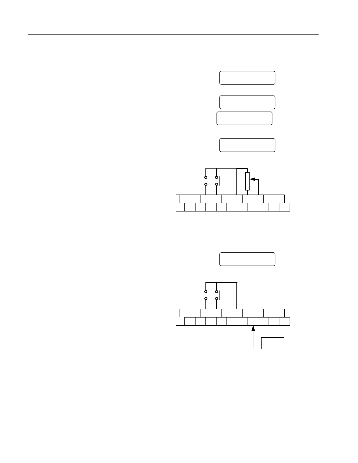
10 ?, 1/2 W
3.2 Operation Using Control Terminal – External Start, Stop and Speed Reference
1. Confirm ‘Manual T/T’ in DRV 00.
2. If different, as in section 3.1 of this chapter, select
‘Terminal’ in FUN 01 and ‘Terminal-1’ or Terminal-2’
in FUN 02.
3. Install a potentiometer on terminals V1, VR and CM
as shown right below. Select ‘V1’ in FUN 20 to control the
speed by potentiometer alone.
4. Set a frequency reference using the potentiometer.
Make sure to observe the set value in DRV 00.
EG
FX RX
RST
P2 P3 P4 P5
DRV¢º Manual T/T
00 FWD 60.00 Hz
FUN¢º Freq. set
01 Terminal
FUN¢ºRun/stop set
02 Terminal-1
FUN¢º V-I mode
20 V
BX CM VR V1
P6 CM I FM
V2 IO
LM CM
5. When a ‘4 - 20mA’ current source is used as the
frequency reference, use terminal I and CM.
Select ‘I’ in FUN 20 to control the speed by the
current source alone.
6. To run the motor in the forward direction, close
the [FX] terminal to the [CM] terminal.
7. To run the motor in the reverse direction, close
the [RX] terminal to the [CM] terminal.
EG
FX RX
RST
P2 P3 P4 P5
FUN¢º V-I mode
20 I
BX CM VR V1
P6 CM I FM
4 - 20mA
V2 IO
LM CM
28
 Loading...