

Lifan 620 Maintenance Manual
www.cargeek.ir
www.CarGeek.ir
www.cargeek.ir

1
www.cargeek.ir
www.CarGeek.ir
www.cargeek.ir
Foreword
LF620 Service Manual on common treatment of troubles is to help you correctly use and maintain
your love sedan.
This manual, with illustrative figures and easy-going words, thoroughly introduces the structure
features, use and maintenance of LF620 sedan, which will be a good guide for wide users and
maintenance technicians. Meanwhile, LF620 Spare Parts List will also be referred if necessary. For
any questions and doubts, please do not hesitate to contact the service stations of Chongqing Lifan
Passenger Vehicle Co., Ltd.
The figures, notes, specifications etc contained in the manual will take effect as of the date of printing,
which can be modified and terminated at any moment by Chongqing Lifan Passenger Vehicle Co., Ltd.
without any notice in advance.
Any comment on any thing improper in the manual shall be preferred, and no responsibility on any
thing improper shall be undertaken by Chongqing Lifan Passenger Vehicle Co., Ltd.
Without a permit from Chongqing Lifan Passenger Vehicle Co., Ltd., any unit or individual shall not be
allowed to duplicate, store, and distribute any part of the manual in any form or by any method.
Great appreciation for your support!
Compiled by: Chai Lichao
Du Tianchuan
October, 2008

Content
2
www.cargeek.ir
www.CarGeek.ir
www.cargeek.ir
Foreword
Content
Part 1 Introduction
Part 2
Chapter I Electronic Injection System
Section I Introduction
Section II Principle of controlling and actuating components
Section III Steps for Trouble Diagnosis with DTC
Section IV Steps for Trouble Diagnosis Based on Engine Symptom
Section V Security Items for System Maintenance
Chapter II Chassis System
Section I Suspension and Axle
Section II Steering System
System Repair
1
2-3
4-19
20-362
20-102
21-21
22-37
38-65
66-101
102-102
103-158
103-115
116-130
Section III Brake System
Section IV Fuel System
Section V Engine Cooling System
Section VI Intake and Exhaust System
Chapter III ABS System
Section I Function and Composition of ABS
Section II Principle of ABS
Section III Removal and Installation of ABS
Section IV Fault Diagnosis and Troubleshooting
Chapter IV Electrical System
General Rules Trouble Shooting
Section I Instrument Cluster
Section II Power Window
131-151
152-153
154-156
157-158
159-190
159-159
160-162
163-166
167-190
191-269
191-195
196-208
209-215

Section III BCM Central Lock, Burglar Alarm System
3
www.cargeek.ir
www.CarGeek.ir
www.cargeek.ir
216-229
Section IV Electric Side Mirror
Section V Illumination System
Section VI Wiper and Washer
Section VII Audio System
Section VIII Reverse Radar System
Section IX Power Supply and Other Electrical System
Chapter V Air Bag System
Section I Composition, Principle and Safety Rules for Maintenance
Section II Diagnosis & Fault Clearing
Section III Diagnosis of Vehicles after Collision
Section IV Removal and Installation
Section V Scrapping Tips for Air Bag Mould
Chapter VI A/C System
230-233
234-245
246-253
254-260
261-266
267-269
270-288
270-274
275-282
283-284
285-287
288-288
289-322
Section I Introduction
Section II System Layout
Section III Component Maintenance
Section IV Fault Diagnosis
Section V Precautions of Air Conditioning System
Chapter VII Auxiliary Component System
Section I Cable
Section II Windshield
Section III Safety Belt
Section IV Front Side Door
Section V Rear Side Door
Section VI Seat Assembly
Section VII Inside & Outside Decorations
289-292
293-296
297-309
310-320
321-322
323-357
323-323
324-327
328-329
330-331
332-333
334-341
342-357
Chapter VIII Vehicle Body Dimension
358-362

4
www.cargeek.ir
www.CarGeek.ir
www.cargeek.ir
Part1 Introduction

Chapter I Entire Vehicle Overview
5
www.cargeek.ir
www.CarGeek.ir
www.cargeek.ir
LF620 sedans are devised to give expression to the human orientation with features of portable
operation, comfortable ride, spacious inner room, excellent dynamic quality and economical
efficiency. The high tech and low price endow them with the stronger market competition.
I. Engine assembly
1. Either the engine of TRITEC1.6L or LF 481Q3 is adopted, which is a single overhead camshaft
multi-point electronic injection engine with 16 valves.
II. Chassis
1. The McPherson independent suspension is applied in the front suspension; and the dependent
trailing arm suspension is adopted by the rear suspension. It also enjoys the design of the elastic
elements and the shock damper of the front and rear suspensions, director elements and stable
ones of the front sub-frame suspension.
2. Steering gear: The steering column employs the angular adjustable mode.
3. Operation system: Clutch pedal mechanism, hydraulic clutch operating device.
4. Both the front and rear brake gears are the vented disc brakes with reasonable load layout and
the Anti-Lock Brake System, namely ABS safety device. It is used to prevent sliding and dragging
on the road due to locked wheel when the vehicle brakes so as to improve the vehicle’s directional
stability, steering control ability and shorten the braking distance so that the braking will be more
efficient and safer. It greatly promotes the safety and reliability of the vehicle in various road
conditions and the reasonable distribution of the front and rear braking force.
5. 195/60R15 tires are used; the tire rim, 6J.
III. Body:
1. An integral body is adopted which has passed the frontal impact test and qualified by the state
testing institutions. Exterior design is fashionable with excellent aerodynamic performance with
streamline figure.
2. The dash board, exterior trims and lighting equipments employ the novel craftworks and
materials.
3. A/C system: It gives full expression to the ergonomic, after the filtration, offering clean and fresh
air evenly and noiselessly.
IV. Electric equipment
The electric equipment design of LF620 sedans absorbs all the electric options so as to meet
diversified customers’ needs.
1. Engine and electronic fan
The engine is equipped with a starter and a generator. Double electronic fans at two
speed-adjusting levels are arranged.
2. Power start, charging systems
The power start system mainly deals with the model and specs size confirmation of the engine,
battery and generator and voltage regulator, etc.

3. Ignition and electronic injection system
6
www.cargeek.ir
www.CarGeek.ir
www.cargeek.ir
① Ignition switch: Only the mature products can be employed and the corresponding current is set
to satisfy the functional requirement.
② The engine is the mature product of the TRITEC and the electronic injection system adopts the
multi-point electronic injection system supplied and calibrated by the SUN & TECK or the Delphi.
The key components of this type’s system include the sensor, the engine control unit, the air inlet
pressure temperature sensor, the throttle valve assembly, the knock sensor, the oxygen sensor,
camshaft position sensor, crankshaft position sensor, coolant temperature sensor, weak
acceleration sensor, canCV canister control valve, fuel rail assembly, ignition coil, and the catalytic
converter etc.
4. Warning signal
The design for the control of the circuit system has been devised correspondingly to satisfy the
requirement of the entire vehicle and the state legal regulations.
The warning signal devices are used to warn and hint signals to the surrounding environment,
including the horn, steering indicator, emergent lamp switch, reversing lamp and brake lamp and
switches, front and rear fog light and so on.
5. Instrument assembly
1) Instrument cluster: Instrument cluster of the electronic odometer. The instruments include the
water thermometer, engine tachometer, speed odometer and the fuel gauge.
2)Indicators include: The battery charge indicators, engineer oil pressure indicator, brake fluid
level indicator, engine malfunction detecting indicator, handbrake indicator, safety belt indicator,
fuel warning indicator, instrument lighting light, high beam indicator, steering (emergency) light,
ABS indicator, door ajar indicator. Reverse radar display, fuel flow sensor, engine oil pressure
sensor, vehicle speed sensor, handbrake switch, door lamp switch, brake shoe sensor, safety belt
contact switch, brake fluid level sensor, parking brake (handbrake) switch etc.
6. Auxiliary electrical devices
(1) Front windshield wiper system: controlled by a combination switch handle. The wiper motor
and the connecting rod are collocated in front of the dash panel.
(2) Radio: Four speakers with adjustable high pitch function. CD player, DVD player, and backup
monitor are optional.
(3) Audio system
Single disc CD player and optional DVD on the dash board, six speakers with radio reception, disc
playing and time display functions simultaneously. This novel and nice CD, DVD player own six
interfaces respectively so six disc players are acceptable according to the customers’ needs.
(4) Cigarette lighter: one, installed for convenience, collocated according to the formative
necessity.
(5) Rear defrosting: The heating-type glass is employed for the rear window and controlled by the
switch.
(6) Self-closing four-door window functions: four-door collocation, master control at driver side and
independent control for right doors and windows, the operating switch collocated on the door
armrest.
(7) Central lock: for four doors, unified switch. Remote control, mature products selected
according to the body structure and modeling and adoption of the BCM centralized control.
(8) Electronic anti-theft device: Controlled collectively by the BCM so as to realize the function of

electronic anti-theft.
7
www.cargeek.ir
www.CarGeek.ir
www.cargeek.ir
(9) A/C system: JSS-120 swinging-vane type compressor with delivery capacity 120ml/r and
excellent refrigerating effect, consisted of the condenser, evaporator, thermostat, sensor, pressure
switch and blower, etc.
7. Safe anti-theft device
(1) Air bag: The electric double air bags are located on the steering wheel and the dash board of
the co-driver room respectively.
(2) The ABS safety device of the Anti-Lock Brake System guarantees the safety and reliability of
the vehicle’s brake system.
(3) Anti-theft device (optional)
The anti-theft system is mainly controlled by the body controller BCM, connected to the engine
ECU by a communication link. When the ignition key is plugged in, if the signal detected is correct,
the ignition system will work normally; otherwise, the engine can not work. This is the anti-theft
system in common use.
8. Other electric devices:
The other electrical devices mainly include the harness, center control box, relay, safety lever,
interface, switch, corresponding fixing bracket and the strapping components.
Chapter II Main Technical Parameters of Lifan Vehicles
8
www.cargeek.ir
www.CarGeek.ir
www.cargeek.ir
I. Basic performance parameters
1. Complete vehicle basic parameter (Table 1)
2. Complete vehicle performance index (Table 2)
Table 1 Complete Vehicle Main Parameter
Item LF7162 sedan
Type
Drive model Front lateral engine, front-wheel drive
Length mm 4545
External dimension
Track
Trafficability
characteristic
Width mm 1705
Height (idle load) mm 1495
Wheel base mm 2605
Front track (idle load) mm 1470
Rear track (idle load) mm 1460
Front suspension mm 935
Rear suspension mm 995
Approach angle ( ° ) 20
Departure angle ( ° ) 23
Minimum ground clearance mm 170
Minimum turning radius m 10.2
3 compartments, 4 doors, 5 seats and 2
covers
Mass
Luggage boot capability L ( 300 )
Complete vehicle weight kg 1150
Axle load distribution
(front/rear)
Full load weight kg 1555
Axle load distribution
(front/rear)
Full load distribution
percentage (front/rear)
Mass center height (no/full) mm 593
kg 710/440
kg 810/745
﹪
51/49

9
www.cargeek.ir
www.CarGeek.ir
www.cargeek.ir
Table 2 Complete Vehicle Performance Parameter
Item LF7160
≥180km/h (BMW 1.6) ≥170km/h
(Domestic vehicle 1.6)
Performance
parameter
Maximum vehicle speed Km/h
Acceleration performance
( 0-100km )
Fuel consumption of uniform
speed traveling
Maximum climbing angle
Number of passengers People 5
s
L/90km 5.64
(﹪)
II. Structure and Parameter of Main Assemblies
1. Main technical parameters of engine assembly (Table 3, Table 4)
Table 3 Main Performance Parameter of TRITEC1.6L Engine
<15.5
≥35
Item Parameter
Engine type Four-stroke electronic gasoline injection engine
Delivery capacity 1598cc
Engine model 4 cylinders in line
Camshaft model Single overhead camshaft
Rocker arm model
Combustion chamber Single cylinder 4 valves
cylinder bore ×stroke 77mm×85.8mm
Compression ratio 10.5 : 1
Supply system Multipoint fuel injection system
Maximum torque 157Nm/4550rpm
Maximum power 87Kw/5600rpm
External dimension 440×564×670
Minimum fuel consumption 248g/Kw.h
Rocker arm shaft with midpoint support , 8mm chain
driven by hydraulic force

10
www.cargeek.ir
www.CarGeek.ir
www.cargeek.ir
Table 4 Main Performance Parameter of LF481Q3 Engine
Item Unit Model and parameter
Four-stroke, water cooling, 4 cylinders in line,
Model
Cylinder bore mm 81
Stroke mm 77
Total delivery capacity L 1.6
Compression ratio 9.5:1
Lubricant capacity L 4
Fuel No. 93# unleaded gasoline
Engine oil No. Not lower than SG grade (GB11121-1995)
Starting mode Electric start
16 valves, double overhead camshafts and
multipoint electronic injection
Lubricating mode Pressure and splash combined type
Cooling mode
Rated rotation speed r/min 6000
Rated power Kw 78
Maximum torque ( 3505000_r/min )
Minimum fuel consumption g/kw.h ≤270
Minimum idle load stabilized rotation
speed (idle speed)
Emission limit at idle speed
Ignition advance angle (idle speed) 5±3º
Forced circulating water cooling
N·m /rmp 137N·m / 3500rmp
r/min 800±50
Low idle
speed
High idle
speed
CO≤0.3%, HC≤80ppm
CO≤0.2%, HC≤60ppm
Intake valve clearance (cool)
Exhaust valve clearance (cool)
External
dimension
0.20~0.25
0.25~0.30
mm
Without transmission 650×605×640
With transmission
1010×605×640

11
www.cargeek.ir
www.CarGeek.ir
www.cargeek.ir
2. Model and parameter of main assemblies of chassis (Table 5)
Table 5 Model and Parameter of Main Assemblies
Name Structure and parameter
Exhaust system Three-way catalytic converter (one section) and muffler (two sections)
Intake system Intake pipeline and air cleaner
Fuel supply system
Cooling system Ribbon-tubular radiator and electronic fan
Clutch pedal force ≤140N
Clutch pedal maximum play ≤100mm
Drive shaft Model Tri-pin sliding bush end, Rzeppa fixing end
Suspension
Tire
Including fuel pump, fuel cleaner, pressure regulator, accelerator pedal,
fuel tank
Front suspension MacPherson independent suspension
Rear suspension dependent suspension with a torsion beam
Tire type Radial ply tire
Tire specification 195/60 R15
Rim specification 6J×15
Tire pressure 2.3MPA
Steering gear model Rack and pinion hydraulic power steering
Wheel alignment
Brake system
Steering equipment
Front wheel camber 0°30′±45′ (idle load)
Front wheel toe-in
Kingpin inclination angle 3º±30′ (idle load)
Kingpin caster 11°15′±45′ (idle load)
Structure model
Driving brake Disc brakes for both front and rear wheels
Parking brake Mechanical cable rear wheel rim brake
Pipe angle can be adjusted, steering wheel
external diameter 375mm
-2~2
Hydraulic dual-pipe, with vacuum booster
and ABS

12
www.cargeek.ir
www.CarGeek.ir
www.cargeek.ir
3. Vehicle body structure model and parameter (Table 6)
Table 6 Vehicle Body and Inner and Outer Trim
Name Structure and parameter
Vehicle model
Body-in-white All metal closed type structure
Vehicle
body
Inner and
outer
trims
Door assembly
Engine hood Open backward, bent arm hinge
Front and rear bumpers Injection molding
Inner trim Injection molding with surface texture
Dash board Injection molding with surface texture
A, B and C pillars and indoor shield Injection molding framework, knitted surface
Windshield
Rearview mirror
Integral body, 3 compartments, 4 doors, 2 covers and 5
seats
Framed, 4 doors open in regular direction, card lock, with
side bumper
Front windshield: laminated glass,
rear window: Toughened glass
Outer rearview mirror: Convex mirror in both left and right,
manual/automatic adjustment
Inner rearview mirror: Anti dazzle
Front seat: independent seat, adjustable back and forth
Seat
Structure model Compressive refrigeration, water heating
A/C
Operation
Refrigerant Model R134a, filling 500g ± 50g
position, backrest angle, headrest and so on; rear seat
with safe belt: dependent seat, unadjusted
Adjusted with knob to control air flow direction, to control
and adjust air flow speed, temperature and air circulation;
luxurious ones with electric adjustment

4. Structure and parameter of electrical system (Table 7)
13
www.cargeek.ir
www.CarGeek.ir
www.cargeek.ir
Table 7 Structure and Parameter of Electrical System
Name Structure and parameter
Wire Single wire, negative pole grounded, direct current 12V
Generator Integral type, AC, built-in voltage regulator, specification 14V/80A
Start
Illumination and
signal
Motor solenoid-operated (with generator), power 1.2kw
Electronic fan Without speed regulation single fan
Battery Maintenance-free plumbic acid battery, capacity 60Ah
Headlamp (55/55W, white, 2 lamps),
Front combination lamp
Side steering light 12V, 0.6W, amber, 2 lights
Front and rear fog lights
Rear combination lamp
Rear license plate lamp 5W, white, 2 lamps
High-mounted brake lamp LED, LED, red, 1 lamp
Inner combination roof light 5W, white, 2 lights
position lamp (0.8W, LED, white),
steering light (21W, amber, 2 lights, both combination switch)
Front fog light (55W, white, 2 lights), rear fog light (3W, LED, red,
combination switch), rear position lamp (1W, LED, red)
Brake lamp (1.2W, red, 2 lamps, contact closed switch),
Reversing lamp (21W, white, 2 lamps), steering light (21W, amber,
2 lamps, combination switch), rear position lamp (0.8W, LED, red)
Instrument
system
Electric assistant
system
Door lamp 6.2W, white, 4 lamps
Instrument cluster
Indicator
Instrument cluster with electronic odometer, including LCD water
thermostat, fuel gauge, vehicle odometer, engine rotation speed
Including battery charge indicator, engine oil pressure indicator, fuel
warning indicator, brake fluid level indicator, engine fault indicator,
handbrake indicator, anti-theft indicator, safe belt indicator,
electronic airbag indicator, instrument illumination light, high beam
indicator, fog light indicator, steering light (emergency lamp)
indicator, ABS indicator, door ajar indicator.
Brake indicator, anti-theft indicator, safe belt indicator, electronic
airbag indicator, instrument illumination light, high beam indicator,
fog light indicator, steering light (emergency lamp) indicator, ABS
indicator, door ajar indicator.
Including CD (or DVD) player, cigar lighter, rear defroster, wiper and
washer, remote door lock, anti-theft system, airbag, window
regulator.

5. Lubricant, fuel, steering fluid, brake fluid, coolant, refrigerant and capacity
14
www.cargeek.ir
www.CarGeek.ir
www.cargeek.ir
(1) Lubricant
Table 8 Lubricant
Lubricant No. Weight
Bearing and button head pin Lithium base grease 7022 0.34kg
(2) Fuel
Table 9 Fuel No. and Fuel Tank Capacity
Name Performance index
Fuel No. 93# or better unleaded gasoline for vehicle
Fuel tank capacity (L) 58L
(3) Steering fluid, brake fluid, coolant and refrigerant
Table 10 Steering Fluid, Brake Fluid, Coolant and Refrigerant
Name No. Capacity or mass
Power steering fluid ESSO ATED 0.825L
Brake fluid DOT4 0.72L
Coolant Antifreeze G11 8.5L
Refrigerant R134a 500g±50g
Windshield cleaning solvent NFC-60 As necessary

Chapter III Lifan Vehicle Maintenance Routine
15
www.cargeek.ir
www.CarGeek.ir
www.cargeek.ir
LF620 Maintenance Plan can make the vehicle run stably, safely and economically and
reduce faults. Maintenance interval varies according to the odometer or time interval. Please refer
to the plan. Those items that have exceeded the deadline should also be maintained in the same
interval. Rubber hoses (in cooling and heating system, brake system and fuel system) should be
specially maintained. In case of aging, cracking or damage, replace the hose. Only professional
technician can check the vehicle.
Basic maintenance items:
I. Electric equipments on vehicle body
1. Check all the inner and outer lamps and electric equipments: Instrumentation console indicator,
headlamp, front fog light, rear fog light, front position lamp, rear position lamp, front steering light,
rear steering light, brake lamp, reversing lamp, license plate lamp, luggage boot lamp, cigar lighter,
horn, power window regulator, power exterior rearview mirror and ventilation system.
2. Airbag: Visually check if its surface is damaged.
3. Self-check: Read the fault information of all systems in memorizer with Lifan special diagnostic
tools.
II. Outer vehicle body
1. Door limiter, fixed pin, door lock, engine hood, luggage boot cover hinge and buckle: Check the
function and lubricate.
2. Window: Check the function; clean the lead rail and smear special grease.
3. Wiper/cleaning equipment: Adding washing liquid; adjust the nozzle if necessary when checking
the function.
III. Engine compartment
1. Visually check if there is damage or leak for all parts.
2. Cooling system: Check the antifreeze and refill if necessary. Standard value: -25 (℃ -35℃ in
cold area)
3. Power steering system: Check if there is any leak; check the steering hydraulic oil level; and
refill if necessary.
4. Brake system: Check if there is any leak in brake pipeline; check the brake fluid level; and refill if
necessary.
5. Replace brake fluid: Every other 2 years or every 50,000km.
6. Air cleaner: Clean the filter element every 7,500km and replace the filter element every
30,000km.
7. Engine cleaner: Replace the element every 7,500km.
8. Gasoline filter: Replace it every 30,000km.
9. Battery: Check if the positive and negative poles of the battery are tightly connected; check the
electric eye.

IV. Engine and vehicle body bottom
16
www.cargeek.ir
www.CarGeek.ir
www.cargeek.ir
1. Vehicle body bottom: Check if the fuel pipe, brake oil pipe and bottom protection layer are
damaged; check if the exhaust pipe leaks and if fastening is reliable.
2. Steering tie rod: Check the clearance; check if the connection is reliable and if dustproof cover
is damaged.
3. Brake lining: Check the thickness.
4. Parking brake: Check and adjust the length of cable if necessary.
5. Tire (including spare tire): Check the worn condition of tire; check the tire pressure.
6. Wheel alignment: Check with wheel aligner.
7. Wheel fixing bolt: Check according to specified torque.
8. Headlamp: Check and a.
9. Trial run: Check the performance.
Abbreviations in this manual
A
AC Alternating current
ACC Air conditioning clutch
ACMC Air conditioning magnetic clutch
ACT Air charge temperature
A/C Air conditioning
ABDC After bottom dead center
ABS Anti-lock brake system
A/D Aanalog/digit
A/F
AFS
A-ELR
ATDC After top dead center
API American Petrol Institude
ATF Automatic transmission fluid
Air/fuel ratio
Air flow meter (air flow sensor)
Automatic/emergency locking retractor (of safety belt)
ALR Automatic locking retractor (of safety belt)
ASD Automatic switching-over device
A/T Automatic transmission
B
BATT Battery
B+
BBDC Before bottom dead center
Battery positive pole

BOO Brake on-off
17
www.cargeek.ir
www.CarGeek.ir
www.cargeek.ir
BTDS Before top dead center
C
CAB ABS control unit with electromagnetic coil
CANP
CMP Sensor Camshaft position sensor (crankshaft turning angle sensor)
CO Carbon monoxide
CKT Circuit
CPP Switch Clutch pedal position switch (clutch switch)
CPS Crankshaft position sensor
CPU Central processing unit
CVT Continuously variable transmission
CRS Child restraint system
CTS Coolant temperature sensor
D
DC
Canister Purge exhaust valve
Direct current
DLC Digit link connector (series data link)
DOHC Double overhead camshaft engine
DOJ Double offset joint
DRL Daytime running light
DTC Diagnostic trouble code, diagnostic code
DS Detonation sensor
E
ECA Electronic control assembly
EBCM Electronic control module (anti-lock brake module)
ECM Engine control module
ECT Engine coolant temperature
ECT Sensor
EFE Heater Early fuel evaporation heater
EFI Electronic fuel injection
Engine coolant temperature sensor
EGR Exhaust gas recirculation
EGRT Sensor EGR temperature sensor
EMI Electro magnetic interference

ELR Emergency locking retractor
18
www.cargeek.ir
www.CarGeek.ir
www.cargeek.ir
EPS Electric power steering
EST Electronic spark timing
EVAP Evaporative system
EVAP Canister Evaporative system canister
F
FP Fuel pump
FPC Fuel pump control ECU
G
GEN Engine
GND Grounding
H
HC Hydrocarbon
HO2S Heated oxygen sensor
HUC Hydraulic unit control with solenoid valve
I
IAC Valve Idle air control valve
IAT Sensor Intake air temperature sensor
ICM Ignition Control Module
ICU Integrated control unit, composed of four parts
IG
In
ISC Actuator
L
L
LH
LSPV
M
Max
MAF Sensor
MAP Sensor
MFI
Ignition
Inch
Idle speed control actuator
Left
Left hand
Load sensor proportion valve
Maximum
Mass air flow sensor
Manifold absolute pressure sensor
Multipoint fuel injection

Min
19
www.cargeek.ir
www.CarGeek.ir
www.cargeek.ir
Minimum
MIL
M/T
N
N
Ne
NOx
O
OBD
O/D
OHC
P
P
PCM
Malfunction indicator light, engine check light
Manual transmission
Neutral
Engine rotation speed, engine efficient power
Nitrogen oxides
On-board diagnostics
Over-speed driving
Overhead camshaft
Parking
Power control module
PCV
PDC
PIM
PNP
P/N
PSPS
P/S
PSP Switch
PSW
PWR
R
R
RAM
RH
Positive crankcase vent
Power distribution control
Pressure of intake manifold
Park/neutral position
Park/neutral
Power steering pressure switch
Power steering
Power steering pressure switch
Position of throttle wide-open
Power
Right
Random memorizer
Right hand

20
www.cargeek.ir
www.CarGeek.ir
www.cargeek.ir
Part II System Repair

Chapter I Electronic Injection System
21
www.cargeek.ir
www.CarGeek.ir
www.cargeek.ir
Section I Introduction
I. Fundamentals
The electronic injection system is a multi-point fuel injection system with electronic control unit
(ECU). With various sensors installed on different parts of the engine to measure each working
parameter of the engine, the ECU can precisely control the fuel injection volume by controlling the
fuel injector according to the pre-set control program in the computer, and achieve the most
favorable air-fuel mixture for the engine under any working condition. With the control program in
the ECU and relevant actuator, such functions as fuel increase at start, fuel increase at warm-up,
fuel increase at acceleration, fuel increase at full load, fuel decrease at deceleration, fuel cut at
idle speed, and automatic idle speed control are available in this system, which can achieve
special air-fuel mixture for the engine under the special working condition. Therefore, the engine
enjoys good performances in fuel efficiency and exhaust emission, and the service performance of
the vehicle is improved at the same time. Besides, the trouble diagnostic mode in the ECU can
make the researching of troubles much easier.
II. Structure of electronic control system
The electronic control system is divided into the following three parts:
(1) Sensor---Convert various non-electrics physical quantities of the engine into electrics physical
quantities, and then send them to the ECU. The sensors on the engine include: ① Intake
pressure/temperature sensor, ② Throttle position sensor, ③ Coolant temperature sensor, ④
Heated oxygen sensor (front and rear oxygen sensor, only front oxygen senor available under
National III Emission Standard, front and rear oxygen sensor available under National III Emission
Standard+EOBD and in National IV Emission Standard), ⑤ Knock sensor, ⑥ Crankshaft position
sensor, ⑦ Weak acceleration sensor (unavailable under National III Emission Standard
(Simplified), available under National III Emission Standard +EOBD and under National IV
Emission Standard).
(2) Electronic control unit (ECU) is the “brain” for the whole electronic control system, which
analyses and processes all the information from sensors, sends orders to actuator, and makes the
engine work under the best condition.
(3) Actuator is to perform the orders from the ECU. The actuator is the “hand” and “leg” of the
electronic control system, which include: ① Fuel pump, ② Fuel injector, ③ Ignition coil, ④ Idle
speed actuator with stepper motor, ⑤ Canister control valve.
Section II Principle of controlling and actuating components
22
www.cargeek.ir
www.CarGeek.ir
www.cargeek.ir
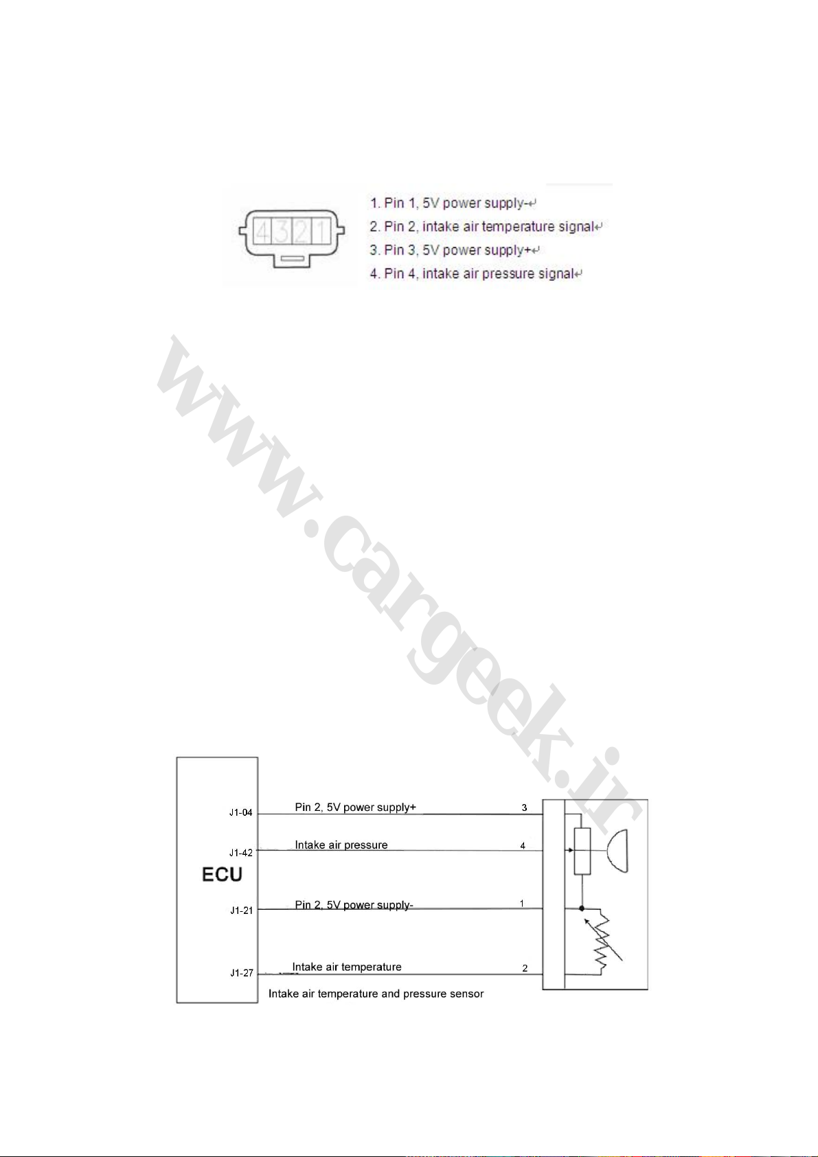
1. Intake pressure/temperature sensor (Fig. 1-1)
Fig. 1-1
(1) Function: Measure the absolute pressure of the 0.1~0.2bar intake manifold and the
temperature of the intake air flow, and provide load information for the engine.
(2) Structure and principle: The sensor consists of intake manifold absolute pressure sensor and
intake air temperature sensor, which is installed on the pressurizer tank.
(3) Intake air pressure sensor: made by a silicon chip. There is a pressure diaphragm on the
silicon chip and are 4 piezoelectric resistances on the diaphragm. The 4 piezoelectric resistances
build up a wheatstone bridge. Besides the pressure diaphragm, there is also a signal process
circuit on the chip. The silicon chip and a metal housing build up a closed referential space, in
which the absolute pressure of the air is approximately zero. Then, a microelectronic mechanical
system is established. There is a zero pressure on the active side of the silicon chip and an
absolute pressure of the intake manifold on the back side of the chip. The thickness of the silicon
chip is only several microns (μm), and the form of the chip will be mechanically changed with the
change of the absolute pressure of the intake manifold. Then, the 4 piezoelectric resistances and
their resistance values will be also changed. After treated by the signal process circuit on the chip,
the pressure signal, which is linearly related to pressure, will be formed.
(4) Intake air temperature sensor: Made by a resistance with negative temperature coefficient
(NTC). Similar to water temperature sensor, the resistance value will decrease with the increase of
the intake air temperature. The change of the intake air temperature will be supervised and
measured by a comparative electric circuit within the ECU.
(5) Connection of wiring diagram (Fig. 1-2)
Fig. 1-2
(6) Trouble diagnosis: The electronic devices of the intake air pressure sensor can diagnose
23
www.cargeek.ir
www.CarGeek.ir
www.cargeek.ir
such troubles as open/short circuit and the damage of senor. When the ECU detects that the
signal output by the sensor is beyond its normal signal curve, the sensor will be in trouble. For
example, when the intake air pressure is higher or lower than its limit, the ECU will confirm that the
sensor is in trouble (The pressure lower than the limit at start will be excluded by the ECU.), then
the engine MIL will be lighted and the operation under trouble mode will be applied.
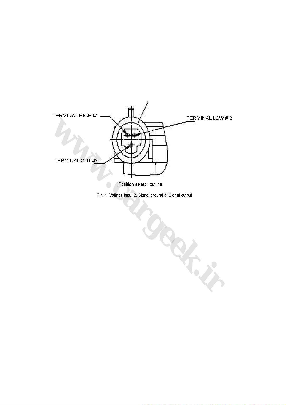
2. Throttle position sensor figure (Fig. 1-3)
Fig. 1-3
(1) Function: To provide throttle-alternator position information to the ECU. According to this
information, the ECU can obtain other information on engine load, working condition (start, idle
speed, backing, partial load, and full load), acceleration and deceleration. With the three-wire
sensor, the ECU can detect the opening of throttle through the change of pressure.
(2) Structure and principle: As an angle sensor with linear output, the sensor is made by two arc
sliding contact resistances and two sliding contact arms. The turning shaft of the sliding contact
arm shares the same axis with the throttle shaft. Power supply voltage (US) of 5V is added to the
both ends of the sliding contact resistance. When the throttle turns, the arm turns and moves on
the sliding contact resistance. Then, the electric potential (UP) at the contact point will be led out
as an output voltage. Actually, it is an angle sensor and the real value adopted by the ECU is the
value of Up/Us, and the value fluctuation of the sensor caused by the fluctuation of the generator
voltage will be avoided.
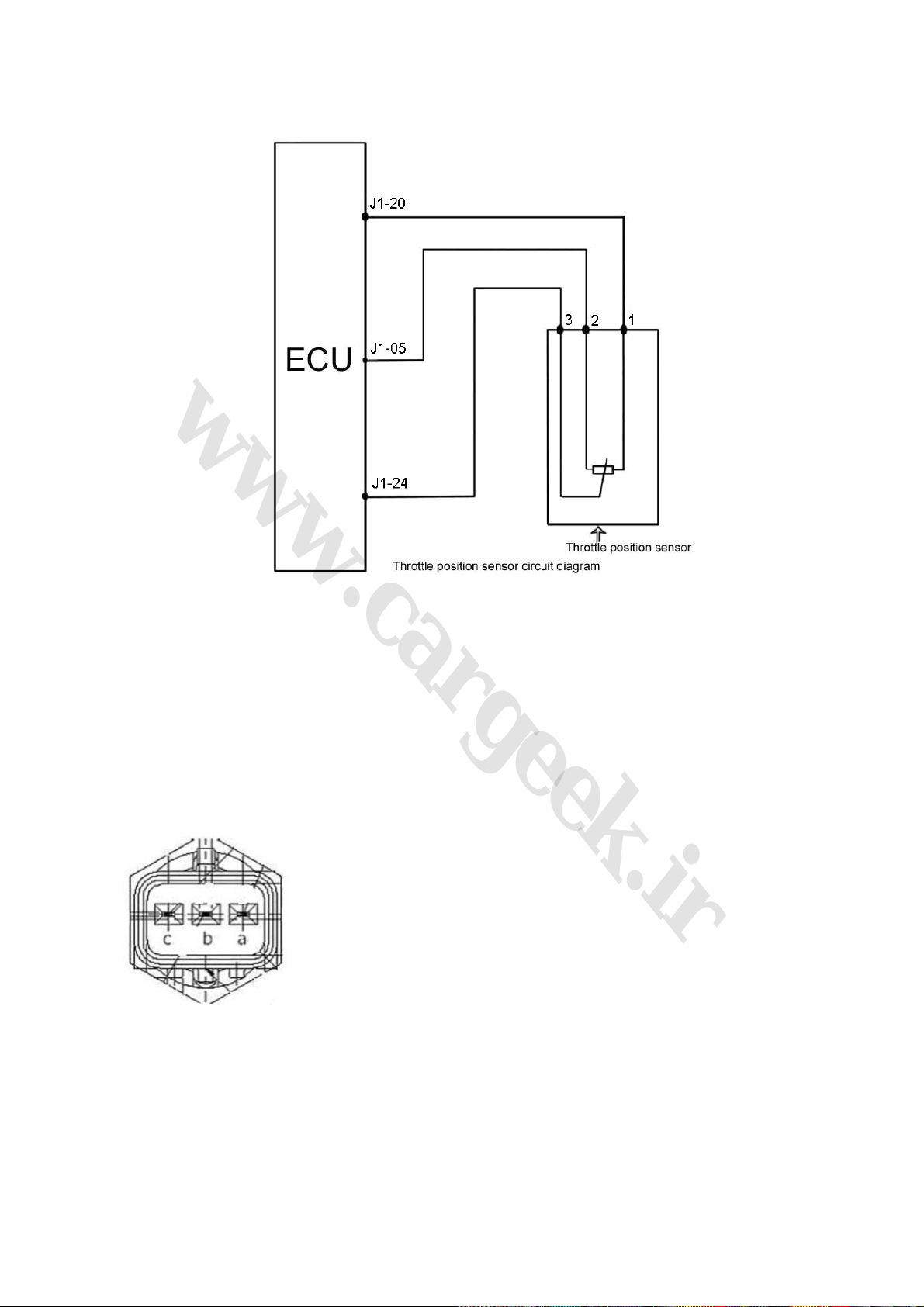
(3) Connection of wiring diagram (Fig. 1-4)
24
www.cargeek.ir
www.CarGeek.ir
www.cargeek.ir
Fig. 1-4
(4) Trouble diagnosis: By monitoring the throttle-alternator position, when the signal higher or
lower than its limit, the ECU will confirm that the throttle position sensor is in trouble, then the
engine operation under trouble mode will be applied, and the engine MIL will be lighted (Knock on
sensor and internal dirt will contribute to engine troubles.)
(5) Installation: Fastening torque for installation screw is 1.5N·m~2.5N·m.
3. Coolant temperature sensor
Coolant temperature sensor
Pin: 3 pins available, equivalent.
a Electronic injection system water temperature signal pin, resistance at 20 : 2.45KΩ℃
b Instrument water temperature pin, resistance at 80 , 0.05 KΩ℃
c Signal ground
Fig. 1-5
(Fig. 1-5)
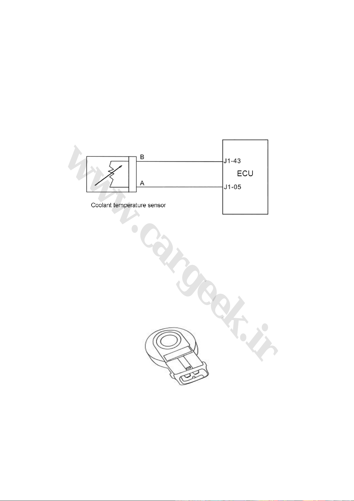
(1) Function: To provide information on coolant temperature. To provide water temperature signal
25
www.cargeek.ir
www.CarGeek.ir
www.cargeek.ir
for the ECU, and to control ignition timing and fuel injection pulse width at start, idle speed, and
normal operation.
(2) Structure and principle: Made by a thermistance with NTC. The resistance value will
decrease with the increase of the coolant temperature (not a linear relation). The thermistance
with NTC is installed within a copper sleeve. With a voltage division circuit, the resistance value of
the thermistance is converted into a changing voltage and then provided to the ECU, and then the
change of water temperature can be monitored (internal structure of ECU).
(3) Connection of wiring diagram (Fig. 1-6)
Fig. 1-6
(4) Trouble diagnosis: When the coolant temperature is higher than its upper limit, or lower than
its bottom limit, the engine MIL will be lighted and the engine operation under trouble mode will be
applied. Then, the ECU will carry out the ignition and fuel injection control as per the water
temperature set under the engine water temperature trouble mode, and make the fan run at a high
speed at the same time.
(5) Limit data: 2.5±5%KΩ
(6) Installation note: Tightening torque is 15±2N·m.
4. Shock sensor Fig. KS1-7
(1) Function: To provide engine knock information for the ECU for knock control.
(2) Structure and principle: As a vibration acceleration sensor, installed on the cylinder block of
the engine. The sense element of the sensor is a piezoelectric element. The vibration of the
cylinder block of the engine can be transferred to the piezoelectric crystal through the mass block
within the sensor. Under the mass block vibration pressure, voltage will be produced at the two
KS1-7
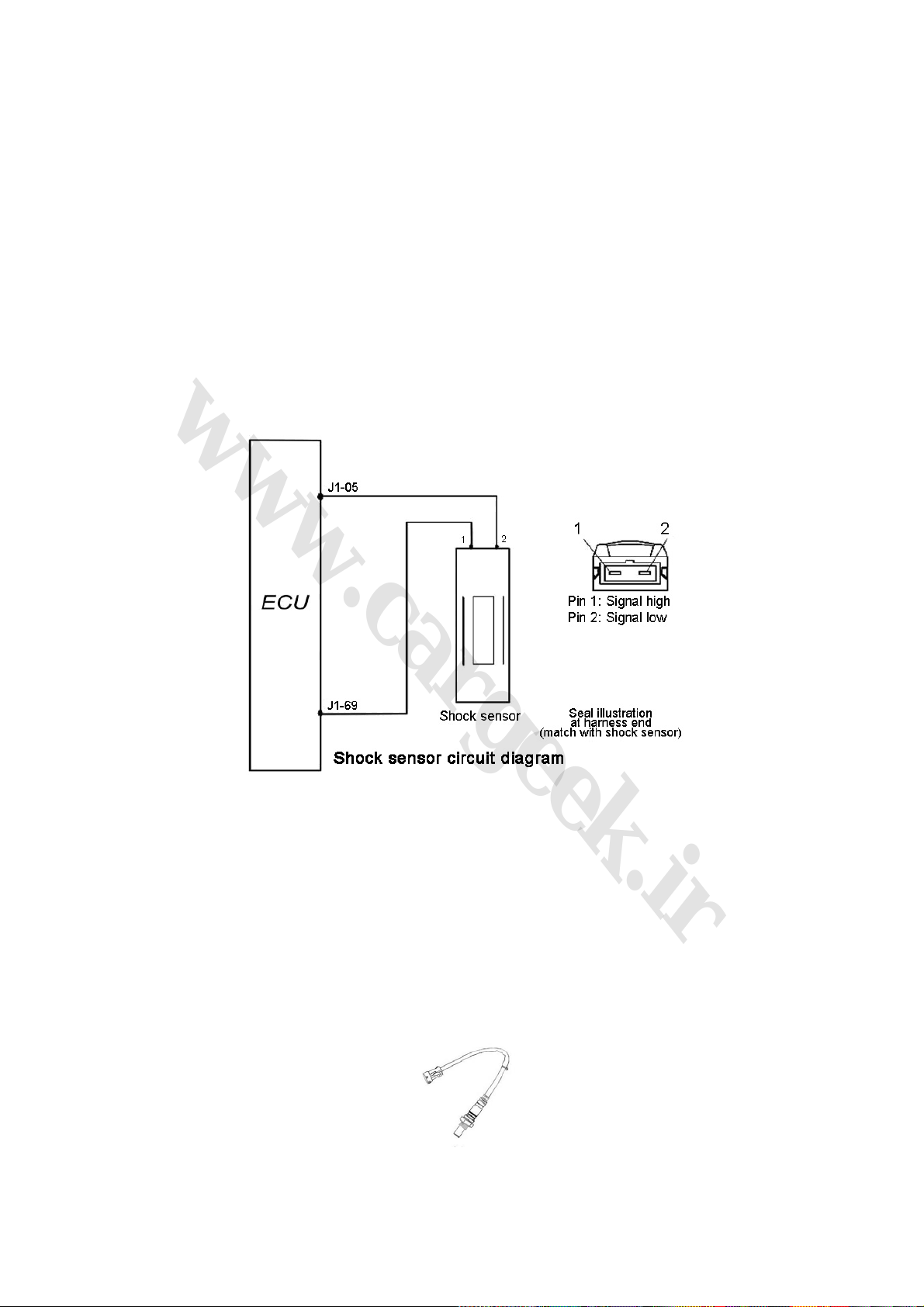
polars of the piezoelectric crystal, and the the vibration signal will be changed into alternately
26
www.cargeek.ir
www.CarGeek.ir
www.cargeek.ir
changing voltage signal and be put out. Since the frequency of the vibration signal caused by the
engine knock is much higher than that of the vibration signal caused by normal engine shock, the
ECU can tell knock signal or non-knock signal after processing the signal with wave filtering
technology. When the load, rotation speed, and coolant temperature exceed the threshold value
and no trouble information record is available for the shock sensor, the signal of the shock sensor
will be used for shock closed loop control. When the shock closed loop control is activated, the
signal of the shock sensor will be sent to the ECU for amplification and wave filtering, and then
accumulated. If the accumulation exceeds the limit within a certain crank angle, the ECU will
confirm that shock occurs and decrease the ignition advance angle at this moment. If shock still
occurs at the next cycle, the ECU will further decrease the ignition advance angle. If no shock
occurs at the following cycles, the ECU will recover the original normal ignition advance angle.
(3) Connection of wiring diagram (Fig. 1-7)
Fig. 1-7
(4) Trouble diagnosis: The ECU will monitor the sensors, actuators, power amplifying circuit and
detecting circuit. In case of any of the following situations, like shock sensor trouble, shock control
data process circuit trouble, unreliable cylinder judgement signal, incorrect shock sensor trouble
mark level, and shock closed loop control closed, the ignition advance angle stored in the ECU will
be decreased for a safety angle. When the trouble frequency is lower than the set value, the
trouble mark level will be repositioned.
(5) Installation notes: The tightening torque for installation is 20±5N·m.
5. Oxygen sensor (Fig. 1-8)
Fig. 1-8
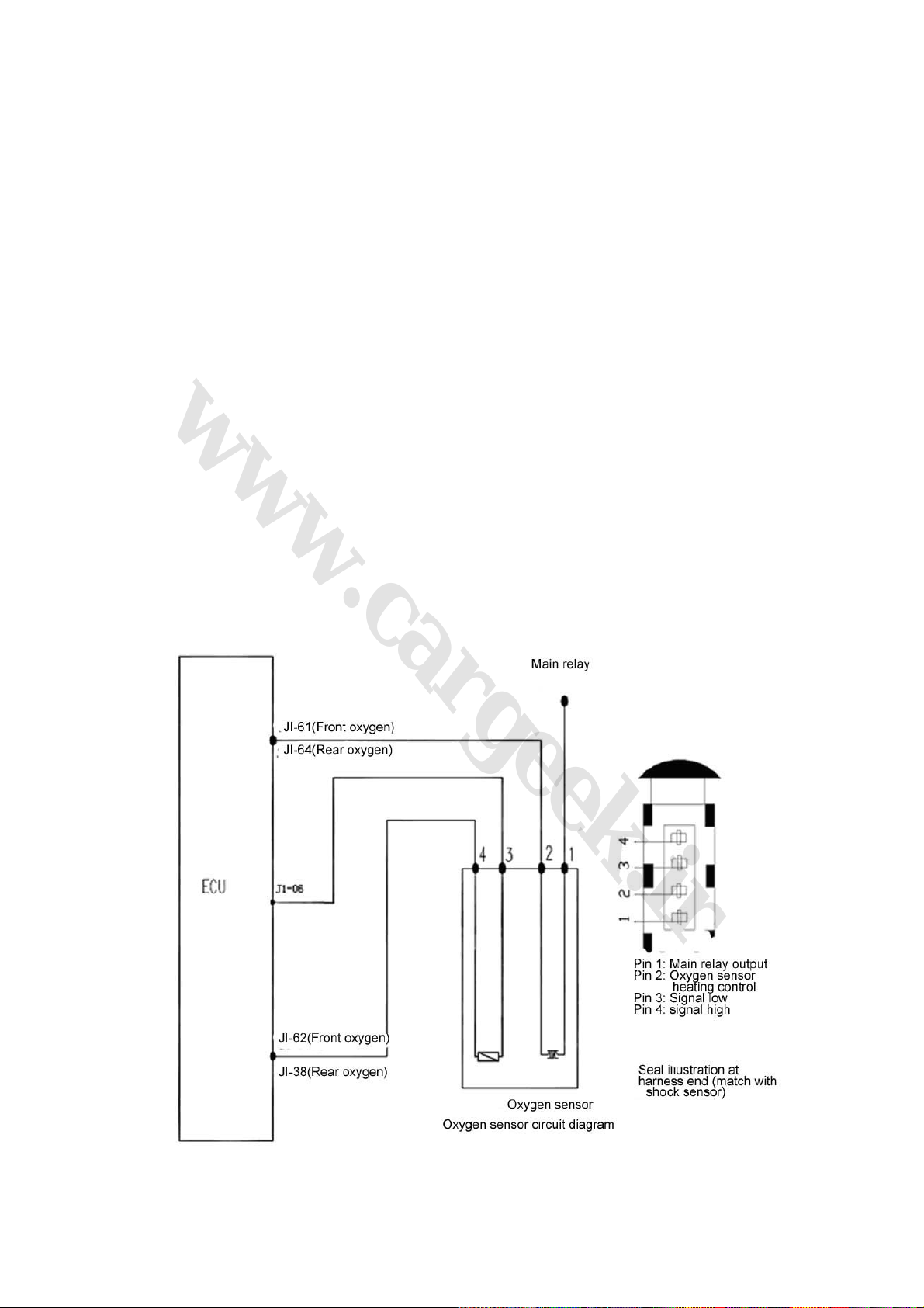
(1) Function: To provide the information that whether oxygen in the cylinder is too high after the
27
www.cargeek.ir
www.CarGeek.ir
www.cargeek.ir
fuel is burned with the air in the cylinder. With this information, the ECU can carry out closed loop
control for the fuel ration. Therefore, the three main toxic elements (HC, CO, and NOX) of the
engine exhaust can be best converted and purified in the three-way catalytic converter.
(2) Structure and principle: The sense element of the oxygen sensor is a ceramic pipe with holes
and gaps. The pipe is surrounded by engine exhaust and the air flows within the pipe. The ceramic
pipe wall is a kind of solid electrolyte with electric heating tube inside, which begins work when the
ceramic pipe has been heated to 300℃ (a feature of a solid electrolyte). With such a special
material, the oxygen ions can freely go through the ceramic pipe. Then, the concentration
difference of the mixture will be converted into potential difference, which will be put out in the form
of electric signal. If the concentration of the mixture is relatively high, the concentration difference
of the oxygen ions inside and outside the ceramic pipe will be relatively high, and the potential
difference will be relatively high as well. At the same time, a lot of oxygen ions will move to the
outside from the inside, and the voltage output will be relatively high. If the concentration of the
mixture is relatively low, the concentration difference of the oxygen ions inside and outside the
ceramic pipe will be relatively low, and the potential difference will be relatively low as well. At the
same time, little oxygen ions will move to the outside from the inside, and the voltage output will be
relatively low. The working voltage of the oxygen sensor fluctuates from 0.1V to 0.9V, which will be
changed for 5-8 times within 10 seconds. In case of lower than the changing frequency, the
oxygen sensor shall be renewed, as it can not be repaired.
(3) Connection of wiring diagram: See oxygen sensor circuit diagram (Fig. 1-9)
Fig. 1-9

(4) Trouble diagnosis: The ECU will monitor the sensors, actuators, power amplifying circuit and
28
www.cargeek.ir
www.CarGeek.ir
www.cargeek.ir
detecting circuit. In case of any of the following situations, like unreliable battery voltage,
unreliable air intake manifold absolute pressure singal, unreliable engine coolant temperature
signal, fuel injector driving stage trouble, incorrect oxygen sensor trouble mark level, and fuel
ration closed loop control closed, the fuel ration will be confirmed according to the basic fuel
injection time stored in the ECU.
(5) Installation notes: The tightening torque of the oxygen sensor is 50~60N·m. Apply anti-rust
oil to the renewed oxygen sensor to prevent difficult removal due to rust.
6. Electronic control unit (Fig. 1-6)
(1) Function: The ECU is the key part of the electronic control system of the engine. The sensors
provide various signals to the ECU, and the ECU calculates the signals and sends orders to the
actuators like fuel injector, ignition coil etc to control the engine.
(2) Structure: Made by a shielded housing and printed circuit board, many electronic control units
integrated on the board to control the electronic injection system.
(3) Installation: Fixed under the instrument panel sundries box with bolt, the double interfaces
ECU is adopted.
(4) LF481Q3 engine controller pin (see Table 1-1, Fig. 1-10)
Table 1-1
Pin
Number
Definition
Pin
Number
Definition
Pin
Number
Definition
J1-01 Ignition switch J1-02 Main relay rear power supply J1-03 Vehicle speed
J1-04 Pin 2, 5V power supply+ J1-05 Pin 1, 5V power supply- J1-06
J1-07 Not used J1-08 Not used J1-09
J1-10 Not used J1-11 Serial data J1-12
J1-13 Not used J1-14 CAN line negative J1-15 CAN line positive
J1-16 Not used J1-17 Power supply 1 J1-18 Power supply 2
J1-19 Not used J1-20 Pin 1, 5V power supply+ J1-21
J1-22 Trouble indicator J1-23 Not used J1-24 Throttle position
J1-25 Not used J1-26 Not used J1-27 Intake air temperature
J1-28
J1-31 Engine trouble indicator J1-32 Ignition switch A J1-33
Crankshaft 58 teeth signal
low
J1-29 Not used J1-30 Not used
Oxygen sensor signal
low
Medium-voltage
switch
Crankshaft 58 teeth
signal high
Pin 2, 5V power
supply-
Idle speed phase B
output positive
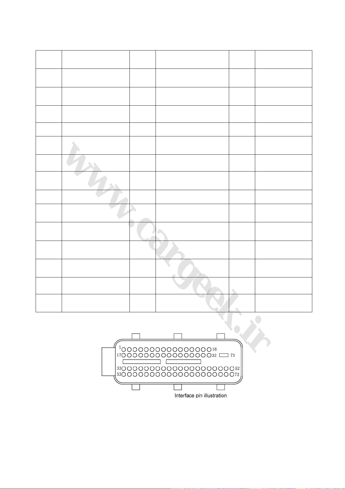
Table 1-1 (Continued)
29
www.cargeek.ir
www.CarGeek.ir
www.cargeek.ir
Pin
Number
J1-34
J1-37 Not used J1-38
J1-40 Not used J1-41 Not used J1-42 Intake air pressure
J1-43 Coolant temperature J1-44 Not used J1-45 Tachometer
Idle speed phase A output
negative
Definition
Pin
Number
J1-35 Acceleration signal J1-36 Power steering signal
Rear oxygen sensor signal
high
Definition
Pin
Number
J1-39 A/C demand (+)
Definition
J1-46
J1-49 Instrument power supply J1-50 High speed fan relay control J1-51 Not used
J1-52 Ignition coil B J1-53
J1-55 Fuel injector of cylinder 1 J1-56 Fuel injector of cylinder 3 J1-57
J1-58 Not used J1-59 Not used J1-60 Not used
J1-61
J1-64
J1-67
J1-70 Fuel injector of cylinder 2 J1-71 Fuel injector of cylinder 4 J1-72 Not used
J1-73 System ground wire
A/C compressor clutch
relay control
Front oxygen sensor
heating control
Rear oxygen sensor
heating control
Low speed fan relay
control
J1-47 Fuel pump relay control J1-48 Not used
Idle speed phase A output
negative
J1-62
J1-65 Not used J1-66 Not used
J1-68 Not used J1-69 Knock signal
Front oxygen sensor signal
high
J1-54
J1-63
Idle speed phase A
output positive
Canister solenoid
valve control
Fig. 1-10
 Loading...