

Lifan 2006 250 V User Manual
PREFACE
Thank
you
for choosing
a motorcycle of the company. May
you
enjoy dding all the time.
The manual
contains the necessary bstuctions and
guidance
with respect to the
opemtion and maintenanc€ of the motorcycle, and BE SURE TO READ IT
CARI-
FULLY BEFORE YOU RIDE THE MOTORCYCLE. Proper
operation and maintenance can
guarantee
a safe riding to minimize troubles
ofthe motorcycle and keep it in
a sound condition, which can extend the
engine service life. Your dealer will
provide you
with technical inquiry and after-sales
service.
The technical datainthe manual are the latest,
andwe reserve
absolute
right to amend them. The manual is
subject to change without notice. Please check carefully
the
product
nameplate,
VIN
record
and engine cod€ in the motorcycle, which
you
have
bought, and they are helpful for
you
to
get
the motorcycle a license
plate
and for future
inquiry.
Important
Notice
Operator and
passenger
This
motorcycle is designed to carry the opemtor and one
passenger.
Never
exceed tbe maximum loading capacity as specified in the manual-
Maximum load
150 kg.
On-road use
This motorcycle is designed to be used only on the road.
READ TIIIS
OWNER'S MANUAL CAREFULLY
.
Pay
special
attention
to statements
preceded
by the following words:
AWARNING
Indicat€s a strong
possibility
of sever€
personal
injury or death ifinstructions are not followed.
CAUTION
Indicates a
possibility
ofpersonal injury or equipmenl damag€ if instructions
are not followed.
Note:
Cives
helpful
information.
This manual should be considercd as a
permanent part
ofthe motorcycle and
should remain with the motorcycle when resold.
CONTENTS
MOTORCYCLE SATE RIDING
2
Main Switch
Safe
Riding Rules
Protective
Cloths
Refitting
Loading and Accessories
PARTS LOCATION AND
VIN
RECORD
Parts Location
VIN Record
2
2
2
2
3
3
4
4
Instruments and Indicator
HaDdlebar Contsols
Clutch Lever
Front Bmke Lever
Gearshift
Pedal
Fuel Filler
Cap
Rear Brake Pedal
Fuel Cock
5
CONTROL
FIJNCTION
Choke lever
Steering Lock
Selection
S€at
Cushion
Helmet Lock
Check and Replace
Adjustment of Front
Bruke
Removing ofRight
Side Cover
Adjusment
of Rear Brake
R€ar Shock Abso.ber
Adjustrn€nt
ofBlake Light Switch
How to
Use
Brake
Wear Indicaton
PRX-RIDD
LNSPECTION
13
13
Brake System
Check ofBrake Fluid fevel
Leak ofBrak€
Fluid
Replacement ofBrake
Adjustment
of Clutch
Thrcttle
Grip
Clutch
Chain
Wheel
Lights
6
6
'7
7
,7
,7
9
9
9
9
9
10
l0
10
l0
ll
11
I2
I2
12
Fuse
Drive
Chain
t4
l4
Engine
Oil
Check
of
Lubdcation
ofcables
Lubrication
of Choke Cable and
Clurch Lever
Rear Brak€
and G€arshift Pedal
Front Brake
and Clutch Lever
Parts,{Fastene$
l4
15
15
16
16
l6
t7
l7
I7
t'7
17
l7
l8
t8
I9
20
2l
Side Stand
Switches
Rear Suspension
Battery
Check ofFrcnt Fork
Fuel
Adjustmed ofRear
Shock Absorber
OPERATION
GUIDE
Check of Steering Device
Starting the Engine
Wheel
Beaxing
Starting Procedure
of Warmed Engine
Battery
Gear shifting
Breaking-in
Replacement of Headlight Bulb
Dismantlement
of Front Wheel
Riding
Braking
Pa*ing
Mounting
of Fmnt Wheel
Dismantlement
of Rear
meel
MAINTENANCE
Mounting
ofRear Wleel
Tool
Kit
Troubleshooting
Maintenance
Schedule
Troubleshooting
Block Diagram
Torsion
Specification
CleaDing
Engine oil
AiI Cleaner
Storuge Guide
Idle Speed
Removal ftom
Storage.....
SPECIFICATIONS
REPORTING
SAFETY DEFECTS
Adjushnent
Spark Plug
of Thrcttle Cable
CDIAGRAM
MOTORCYCLE
SAFE RIDING
Aw,r.nNrNc
Motorcycle
riding requir€s
special efforts on
your part
to ensure
your
safety. Knorv these requirements
below befbre
you
ride.
SAFf, RIDING RULES
l.Always make
a
pre-ride
inspection before
yolr
start
the
engine.
You
may
prevent
accident or cquipment darnage.
2,Manyaccidentsinvo]veinexperienccdriders.Mostcouni|ieSrequireaspccialmotorcycleridingtestorlicense'
your
motorcycle to
an
inexperienced
rider.
3.Many automobilc/motorcycle
accidents happen
because the aulomobile driver
docs not
"see"
the motorcyclist.
Make
yourscllconspicuous
to help avoid the accidcnt that
wrsn't
your
fault:
a
Wear
bdghl or reflective clothing-
aDon't
ride in anothcr
motorist's
"blind
spo."
4-Obey all
national and local laws and regulations.
Exccssive speed is a
facto. in nany accidenis. Obey the
speed
limits,
and NEVER tmvel
faster than condilions wanant.
Signal belore
you
makc a tum or lane change to
draw othcr
nlotorists'
attention..
5.Don't let other motorists
surprise
you.
Use extncaulion at intersections, parkirg
lot entrances and exits,
and always remember to ride
with both hands and keep
borh
feet
on llrc ridcr foorrests while the
passenger grasp
the rear handrail with
both feet on thc
passenger
footrests.
PROTECTIVE
CLOTHS
1'MoStmotorcycleaccidcnt1.ata]itieSareduetoheadinjurieS'ALwAYSwearahelmet'YouShou1da]sowea|alaceshie1dandprotec1ivcclothing.
same
Prolection.
2.ThccxiauStSystembeconrcslrotduringoperation.anditremainshotforawhi1ea1ierstoppingt
clothing that
fully covers
your
legs.
3.Do not
wear loose clothing that could
catch on the controi leve$, kick-stater,
footrests or wheels.
REFITTING
I\WARNING
Relitting
ofthe motorcycle, or r€moval
of original
parts,
may make the vehicle
unsafe or ill€gal.
Obey
all national
and local equipment regulations.
LOADING
AND ACCESSORIES
I\WARNINC
To
prevent
an accident, take
extreme care lvhen adding.ccessories
and cargo and riding with them.
Addition ofaccessories and cargo may reducea
motorcycle's
stability'
performance
and
safe operating speed. Remember these
perlbrmances
may be reduced
by
installation
ofthe rccessories not
produced
by
the company,
improper loading,
worn
tyre
and overall motorcycle conditions,
poor
road or weather conditions.
These
general
guidelines
may help
you
d€cide
whether or how to equip
your
motorcycle, and how to load it safely.
Loading
l.Keep calgo and accessory
weight low and close to the center
ofthe
motorcycle.
Lod weight
equally on both sides to nlininize imbalance. As weight
is located furthcr
liom the motorcycle's
cenler ofgravity, handling is
proportionally
affected.
2.Adjusi t)'rc
prcssure
and rear
suspension
to
suit load wcight and riding conditions.
-
r.\'ehicle
handling and stabiliry can be adversely affectcd by loosc cargo.
Rcchcck
cargo sccurity and
accessory mounts frequently.
.1.Do
not attach items to the handlebars, Iork, or fcndcr. Unstable
handling
or
slow
steering
response may
produce.
ce[uine accessories ofthe company havc bccn spccifically designed
and testcd
on the
motorcycle. Because the factory cannol tesl all other acccssories.
you
are
personally
responsible for seleciion. installation. and use ofaccesso es
not
produced
by the company.
Always lollow lhe
guidelines
under loading, and these below:
LCarefully inspect the a
cortroloperatron.
]'Largc1brkmountcdfairingsor1vindshiclds.orpoorlydesignedorimproper1ymorrntedfairingscanproduceaerdyn
inslall
fairings that decreasc cooling
air flowing to the engine.
i.Accessories may increase the tirne lhat hands of feet operatc controls,
resulting
in incrcascd rcaction
time in an emergency.
.+.Do
Dot add electical equipmcnt that will cxcccd
the motorcycle's electrical system capacity.
i.This motorcycle is not designed to
pull
a sidecar or trailcr. Handling
may
be seriously impaired if so equipped.
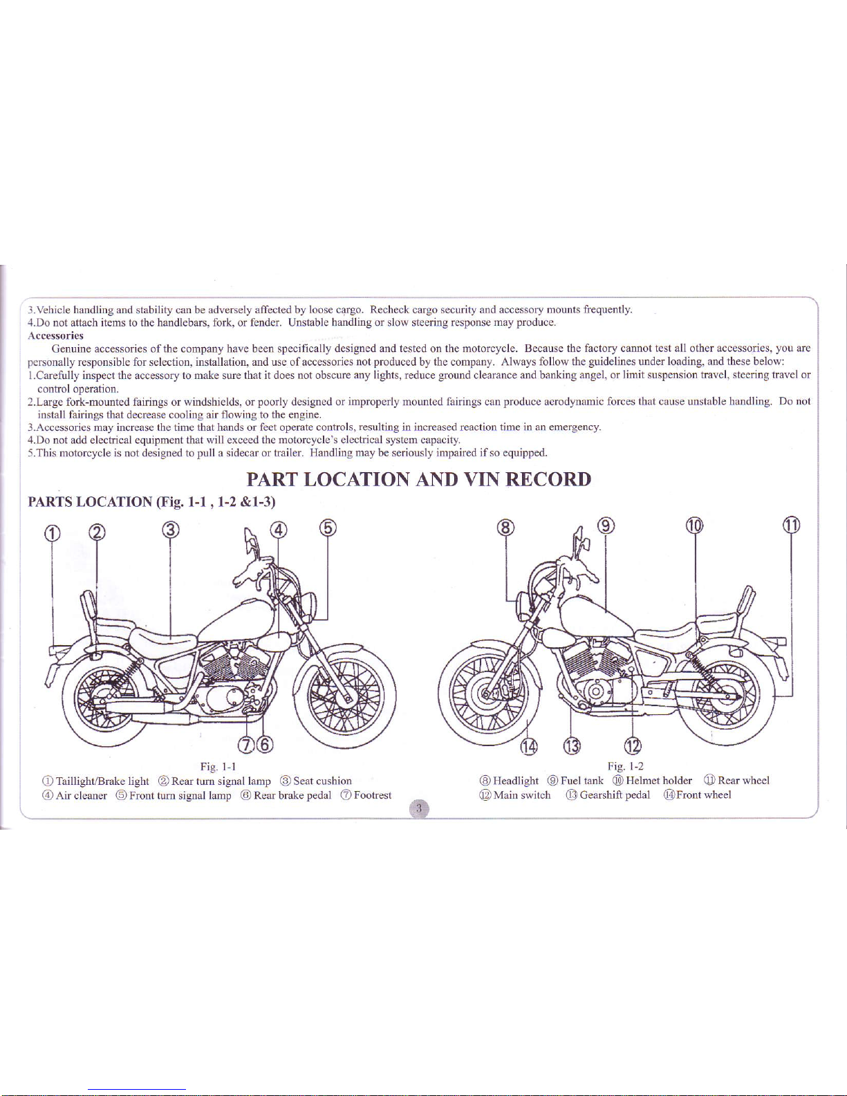
PART LOCATION AND VIN RECORI)
PARTS
LOCATION
(Fig.
l-l , 1-2 &l-3)
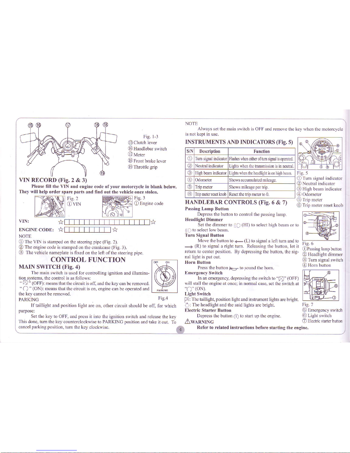
Fig. 1-1
G)
Taillight/Brake light O Rear tum signal lamp @ Seat cushion
@,A.ir
cleaner
6Front
tum signal lamp
@)
Rear brake
pedal
eil
Footrest
Fig. l-2
@
Headlight @ Fuel tank
[0Helmcl
holdcr
ORearwheel
@lMain
switch
@Ceurshilt
pedal
@Front
wheel
NOTE
A1lvays
sct the main switch is
OFF
and renlovc
the key
rvhen
the motorcycle
is not
kept in use-
Fig. l-3
f,tClutch
level
@
Handlebar
switch
@ M.t..
LJq
I rOnt braKe le!ef
!9
Tlfoulc
grip
VIN RECORD
(Fig.
2 & 3)
Please fill the VIN and
engine code ofyour motorcycle in
blank below.
They will help
order spare
parts
and find
out the vehicle once stolen.
Fig. 3
tlrrrngrne
cooc
vIN:
*m*
ENCINE
CODE:
*fTfT_fT_I-f-[-l *
NOTE
fD
The VIN
is slamped on the steering
pipe (Fig.
2).
O
The engine code is
slamped on the crankcase
(Fig.
3).
O
The vehicle
naneplate is fixed
on
the let
ofthc steering
pipe.
Fig.2
Ovnt
INSTRUMENTS
AND INDICATORS
(Fig.
s)
s,/l\ Description Function
o
Turn
signalindicatorFlashes rvhen eitheroftum
sienalis operatcd.
at
N eutral indicalor Lishts $hen lhe tnnsmission
is in neutnl.
High bean indicatorLighls when the headlighl
is on hilh beam.
@
Odomelcr Shows accumuldred mileagc.
Tdp melel
Shows mileagcpertrip.
Trip neter rcset knobReset
the trip mcter lo 0.
HANDLEBAR
CONTROLS
(Fig.
6 &
7)
Passing
Lamp Button
Depress
the button to control the
passing
lamp.
Headlight Dimmer
Set the dimmer to
-it
(HI)
to
select high beam
:i
10
select low beaD.
Turn
Signal Button
Move the
button to
<-
(L)
to signal a left turn and to
-"."f
(R)
to
signal a right turn. Releasing the
button. lct il
retum to center
position.
By depressing the button. the
sig-
nal lighl is
put
out.
Horn Button
Press thc
butlon
|<r-
to sound the hom.
trmergency
Switch
In
an emcrgency, depressing the
switch
to
"8"
(OFF)
will
stall
the
cngine at once; in normal case. set the
swilch at
-o"
(oN).
Light Snitch
P::The
taillight, position
lightand insfirment lights
arc brjght
Q)
Turn signal indicator
O
Ncutral indicator
l3i
High beam indicator
@
odometer
ru
I nf metef feset knob
Fig.6
OPassiDg
lamp button
OHcadlight
dimmer
E
Iunl slgDrll swrrcn
@
Hom button
CONTROL
FUNCTION
MAIN SWITCH
(Fig.
4)
The main
switch is used for controlling ignition
aDd illumina-
tion systems, the
control is as follows:
"
ry"
(OFF):
means that
(he
circuit is off, and the key can
be
removed.
"
O
"
(ON):
means that the
circuit is on, engine can be operated and
the
key cannot be removed.
PARKING
Iltaillight
and
position
light
are on. other circuit should be off, for
which
ii:
The headlight and the
said
lights
are brighr
purpose:
Electric
Starter Button
Set the key to
OFF, and
prcss
it into the ignition switch and releasc
the key
Depress the
butfon O to start up the engine.
This
done, tum the key
counterclockwise to PARKING
position
and takc
it out. To
I\WARNINC
cancel
parkjng
position,
tum
tbe key clockwise.
4
Refer to related instructions
belbre starting fhe
Fig. 7
@
Emcrgency switch
(0
Light
switch
O
Electric
starcrbutlon
engine.
CLUTCII
LE\'ER
Locatcd on
the left handlebaf, the clutch levcr bears
siarting s'vitch. Hold
liImly the lcvcr to the handlebar, disengage
the clutch, while
loose the lcver to en-
.rage
the
clutch.
GEARSIIIFT PEDAL
(Fig.
8)
With 5 speed, the
gearshift pedal
locatcd on the
left
of
cngrnc. The
pedal
should be used
togetherwilh the clutch when
the transmission is operated..
FRONT BRAKE LEVER
The fiont bmkc
lcvcr is fitted on the right handlebar.
Opcratc it
will
stop
the front wheel-
REAR BRAKE PEDAL
engine is in seNice or oul ofservice.
Fuel should bc
fillcd il'the tuel tank is empty.
The tuel cock should be set to ON
wben the engine has is startcd.
NOTE
Thc fuel cock
will function undff
vacuum
by
the engine when thc former
is
set
to ON or RES. llthc
pipe
is
not connected with thc carburetor
and its intake
manifold. or leakage ofixel occuls.
the
fucl
cock will work improperly.
CHOKE
LEVER
(Fig.
1l)
The chokc lever is
positioned
on lhe lcfl handlebar. It is
designed to help stating lhc cngine
in cool condition, for rvhich
puryose, put
thc
knob to left. When the enginc is
warmed
up.
the lever is back to odginal
position-
STEERING
LOCK
(Fig.
12)
To lock the steering head,
hrrn the handlebar to right as
far as it will
go,
then insert thc lock into
key
slol
and turn il
counterclockwisc
by l/8 ofa revolution.
To open thc stccring
lock,just tum the key clockwise.
SEAT CUSHION
(Fig.
13
)
To remove the seat cushion. unscrew
the bolt. To reinstall
the seat cushion.
insert the lug ofseat into
the holc in the main
fiame,
then tighten up the bolt.
NOTE
Makc sure that
the he
seat
cushion is mounted securely.
HELMET LOCK
(Fig.
14)
To open
the helmel lock, insert fhe key
into lock
slot.
and
tum it as
shown
in fig. 14. To lock
it.
just
turn the key io original
pPsrron.
,/l\WARNINC
Do not
ride th€ motorcycle if the helmet
is locked to-
getherwith
it, otheriyise, the helmet
may knock something to
caus€ the vehicle to be out ofcontrol
or happen an accident.
REMOVING OF
RIGHT SIDE COVER(Fig.1s&16)
Pull out
the cover as shown in Fig. 16, then.
remove it by
slipping
frontward.
To
install ihe cover, fit thc ring ofthe side
cover onto the
hook of main 1iame, ihen
put
it to
positior.
REAR sHoCK
ABSORBER
(Fig.
u)
Thc shock
absorber has 5 adjustmcnl
positions
for differ
Fig. li
O
Gearshifi
pedal
N. Neutral
F::-:---l
-
-ilrr
lf"l-l
-"rdE?
rw
Fig. l1
O
Choke
lever
Z-rst
7,q
{l
\\i
'
\l
Fig. 12
O
Steering
lock
]'--_---1t
l!
-'la.l
]\rVl
Fig.13
f.\l,Va
l.]
.44,.-
5%1
a--a
l:'4ffi-^l
Fig.1'l
The
pedal
is located on the right sidc ofvehicle.
Depressing the
pedal
by foot,
the rear brake will work.
FUEL FILLER CAP
(Fig.
9)
OPEN
lnscrt thc
key, tum ii
cloclflvise
by 1/4 ofa revolution,
the
cap may De openeo.
CLOSE
Cover the cap and inscrt the
key. tum itto original
position.
qe. 9
Awenntuc
Gl
o'cn
The fuel filler cap must be
locked bcfore the motorcycle
is used.
FUEL COCK
(Fig.
10)
Fuel in
ihe fuel tank is iiltered via thc vacuum cock
to
cnterinlo
the
carburetor-
The fuel cockhas 3
positions
as follows:
ON
With the
fucl
cock
in the
ON
position,
tuel will flow
from
the
main
luel
supply
to the carburetor. lfthe cngjne
is not in
use. tuel will not flow.
Fig.lo
RES
Means rcscrvc tucl.
with the fuel cock in the RES
position.
fuel will flow
from
the
resewe fuel
supply
to the carburetor. Use the
reservc fuel only when the
rnain supply is
gone,
for which
purpose,
set the coct
to PRI
position
and start thc
engine.
then tum it to RES
posilion.
Refill the tank
as
soon
as
possible
after switch-
ing
to RES. This done,
the tuel cock should bc sct
to
ON
position.
PRI
(fil1ing)
With lhc l'ucl cock in lhis
positiod,
firel may flow in
the
system
whenever the
5
ent loads
or idirg conditions. For iirthcr dclail. reler
to ADJUSTMENT
OF
REAR
SIIOCK ABSORBER hereinaticr.
Fig.15
Fig.
17
O
edju"t.'
Check
the
front brake lever and rear brakc
pcdal
ibr proper
free
play.
Adjust
thern
iIDecessary. Check the brake
systcm at low speedjust the vehicle is
started.
lfyou feel soft *'hen operating the
b.akc lever, it rneans the bmke system
is in
dangerous condition.
In fhis casc contact
your
dealer
for assistancc.
BRAKE FLUID
Check thc brake fluid for 1evel.
add it ifneccssary.
Brake fluid rccornmended:
DOT#4
NOTE
.Iffluid
DOT#4
is unavailable. DOT#3 may
be used instcad.
aCheck
the lining ofdisc
brakc.
aChcck
thc brake shoe.
aContact
your
dealcr for assistance ifyou cannot
corrcct thc
problem.
LEAK
OF'BRAKE FLUID
(FRONT)
Check
the
brakc system fbr leakage fro
pipc
uni! or blake cylinclerby applying the brake lor fe$' minutes.
I\WARNINC
Brake fluid may
cause
irritation,
Avoid contacfing \lifh
skin or eyes. In
case ofcontact, flush thoroughly
with water and call a
doctor ifyour eyes were
cxposed. KEEP OLIT
OF
Rf,ACH
OF CHILDREN.
C-4.UTION
aHandle
brake fluid with care because it
can damage
plastic
and
painled
oWhen
adding brake fluid,
be sure the brake fluid tank is horizontal
before the
cap is removed,
or brake fluid may spill ouf.
oUse
only specified brake fluid from
a sealed container.
ONever
allow contaminants such as
dirt or water to entcr the brake fluid tank,
CLUTCH
Check the clutch lever for
propcr
lrcc play
and tunctioning- Adjust the frcc
play
ifnecessary.
THROTTLE
GRIP
Turning the
grjp.
check it for
pfoper
ftrnctioning
and lrcc
play.
Adjust the
fiee
play
ifnecessary.
Make
surc that the
grip
is back to original
position
actuated by torsion spring.
Ifnot
so, contact
your
dealer for adjustment.
ENGINE
OIL
(Fig.
18)
The
qualiiy
ofthc engine oii
piays
a vitalrole
in dcciding the engine
perfbr-
mance
and servicc lile. Engine oil must
be sclcctcd in accordance with the rules
belorv and othcr oils, such as ordinary machine
oil.
gear
oii and vegetable oi1, are
Fig. 16
O)
Stana
O
Ltook
PRE-RIDE INSPECTION
I\WARNING
lf the
Pre-ridc inspection is not
perlbrmed,
sevcre
personal
iniury
or ve-
hicle damage may result.
lnspect
your
nrotorcycle every day before
you
ridc it. The items
listed here
will
only take a fcw mirutes to inspect.
and in thc long run they can
save tinc,
expcnsc, and
possibly yorr
life.
ITEM
ROUTINE CHECK
Front brake
Check it for
properfunction.
free
play,leak
ofbrake l'luid.
Add
brake fluid DOT#.1(or
DOT#l) ifnecessary.
Rearbrake
Chec\ ir for fur, riol Jnd frcc
plcl,
dJtu.. ri n<ce.sdn.
Clutch
Check it ibr
funclion and freeplay, adjust it ifnecessary.
Throttle lever
(
hcJk rr lo".moorh
oper
rg.
ori
erw
,c
adlLr:r
dnd
. rb-."re ir.
Ensinc oil
Chcck u I le!el, rdd rhe orl ifneces$ry.
Dri!echain
C heck rt for
troper
rension.
or adiLrst ir ifnecessrry.
Tye/uheel
Check itforprcssurc, won, damage andspoke lighiness.
Control/m€ter cable The
operation should be smoolh, orlubricdte it i[necessary.
Brake
&
gearslrift
pedal pin
The
operarion shoJld be.muolf. of I rb-cxre l rt I e.
Lc,rf).
Brake & clutch col]trolpi|ot
The operation shoxld b€
smooth, or
llrbricalc it ifnecessary.
Iheone?rion
'hould
bc
srnoorh,
or 1-bri(drc il ilnece,d-\.
(
hLc(
Jllul lhe n. or lrfl-ren un or ao usr
rhe
n i' ncccq.an.
Fueltank
Check tuel amount.
or
add it iI ncccs\i4.
fights and
irgnal
lamp
Check then forproper
irnciioning.
Batlcry
Chcck the electrolyte amount,
or add distilled water if necessary.
NOTE
Concct any discrepancy
belbre
you
ridc. Contact
your
dealer for assistance
if
you
cannot correct
thc
problen.
BRAKE
SYSTEM
BRAKE
LEVER AND PEDAL
 Loading...