

Page 1

Lierda Science & Technology Group Co., LTD
User’s manual
Address: Lierda Building, 425 Dengyun Road, Hangzhou, China Tel:0571-88800000 Fax: 0571- 89908080
Page 2

1 Product Overview ................................................................................................................................................... 1
1.1 Features ............................................................................................................................................. 1
1.2 Parameters ................................................................................................................................................... 1
1.3 Applications ................................................................................................................................................. 1
2 Hardware Overview ........................................................................................................................................... 2
2.1 Appearance ........................................................................................................................................ 2
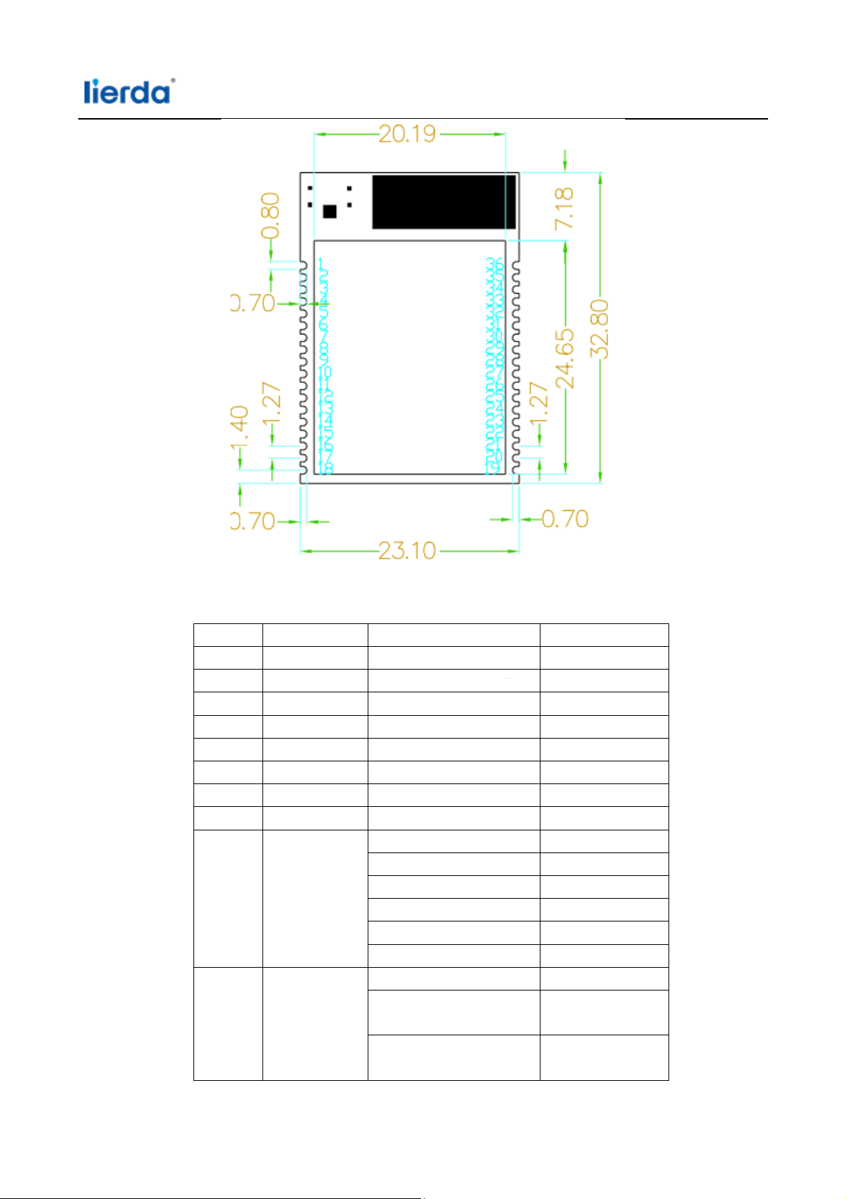
2.2 Product structure size ........................................................................................................................ 2
2.3 Distribution Pin Description ............................................................................................................... 3
3 Functional Description ....................................................................................................................................... 6
3.1 Networking features ..........................................................................................................................
3.1.1 AP Networking ........................................................................................................................... 7
3.1.2 AP Ne
tworking ........................................................................................................................... 7
3.2 Passthrough mode ............................................................................................................................. 7
4 Instructions for use ............................................................................................................................................ 7
4.1 Network Connection .......................................................................................................................... 7
4.1.1 Serial Port Configuration ............................................................................................................ 8
4.2 Creating Socket .................................................................................................................................. 8
4.2.1 Creating a SocketA ..................................................................................................................... 8
4.2.2 Creating a SocketB ..................................................................................................................... 9
4.2.3 Pass
through Mode ................................................................................................................... 10
5 Warning ........................................................................................................................................................... 10
6
Address: Lierda Building, 425 Dengyun Road, Hangzhou, China Tel:0571-88800000 Fax: 0571- 89908080
Page 3

1 ProductOverview
LSD4WF-3211I5SSisLSDTechnologyCo., Ltd. developedultra-low-power embedded WIFImodule, using the
industry's lowest power, high-performanceembeddedprocessorsWIFInetwork. Integratedhardwaremodulewithin
theMAC, radiotransceiverunit, poweramplification unit, developedfor usersto useM4 coreunitsupports802.11b /
g / nprotocol standards; LSD4WF-3211I5SS modulara low-powerWIFImodule, can help customersachieve
productupgradewirelessnetwork communicationstothebasicserial communication.
1.1 Features
Supports802.11 b / g / nprotocol standards, WPA / WPA2 encryption;
supportSmartconfigconfiguration anda APkeyconfiguration;
integratedTCP / IPprotocol stack,reducing theprogramming burden;
containCortex M4core,friendly developmentenvironment;
Simplylinkprovide networkprogramminglibraryandM4 coredriver library;
provide a richperipheral interfaces, UART / SPI / I2C / I2S / PWM, etc.
low power
UnderLPDSmode, the operating current 2ma;
ultra-smallsize of23 * 32mm,surface mountpackage;
Easy to useIAR / CCScompiler environment;
consumption,HIB, the operating current 4ua;
1.2Parameters
optionalexternal interfaceUART / SPI / I2C / I2S
own internalnetworkMAC
network protocolstandard802.11 b / g / n20
2.4Gnetworkoperating frequency
transmitpower: 802.11b: 15dBm+/-1.5dB
802.11g: 11dBm+/-1.5dB
802.11n20: 10dBm+/-1.5dB
Receiving sensitivity: 802.11b -94.5dbm (8% PER)
802.11g -73dbm10% PER 54M@OFDM
802.11n -70dbm
Undercurrent--HIBmode: 4ua;
Undercurrent--Idle Connectmode: 2ma (DITM = 1);
hardwareencryption: WEP, WPA, WPA2;
antennaconfigurations:on-boardPCBantenna andexternal antennaonboard;
modulepin count: 48pin;
module size: 23.1 * 32.8mm;
10%PER MCS7
1.3Applications
Smart HomeApplications
white goods
handheldnetworkdevices
wirelessnetworking applications
remoteequipment monitoring
Address: Lierda Building, 425 Dengyun Road, Hangzhou, China Tel:0571-88800000 Fax: 0571- 89908080
1
Page 4
e
c
o
d
p
r
l
O
s
w
e
7
7
2
nsumerwire
ess product
2 Har
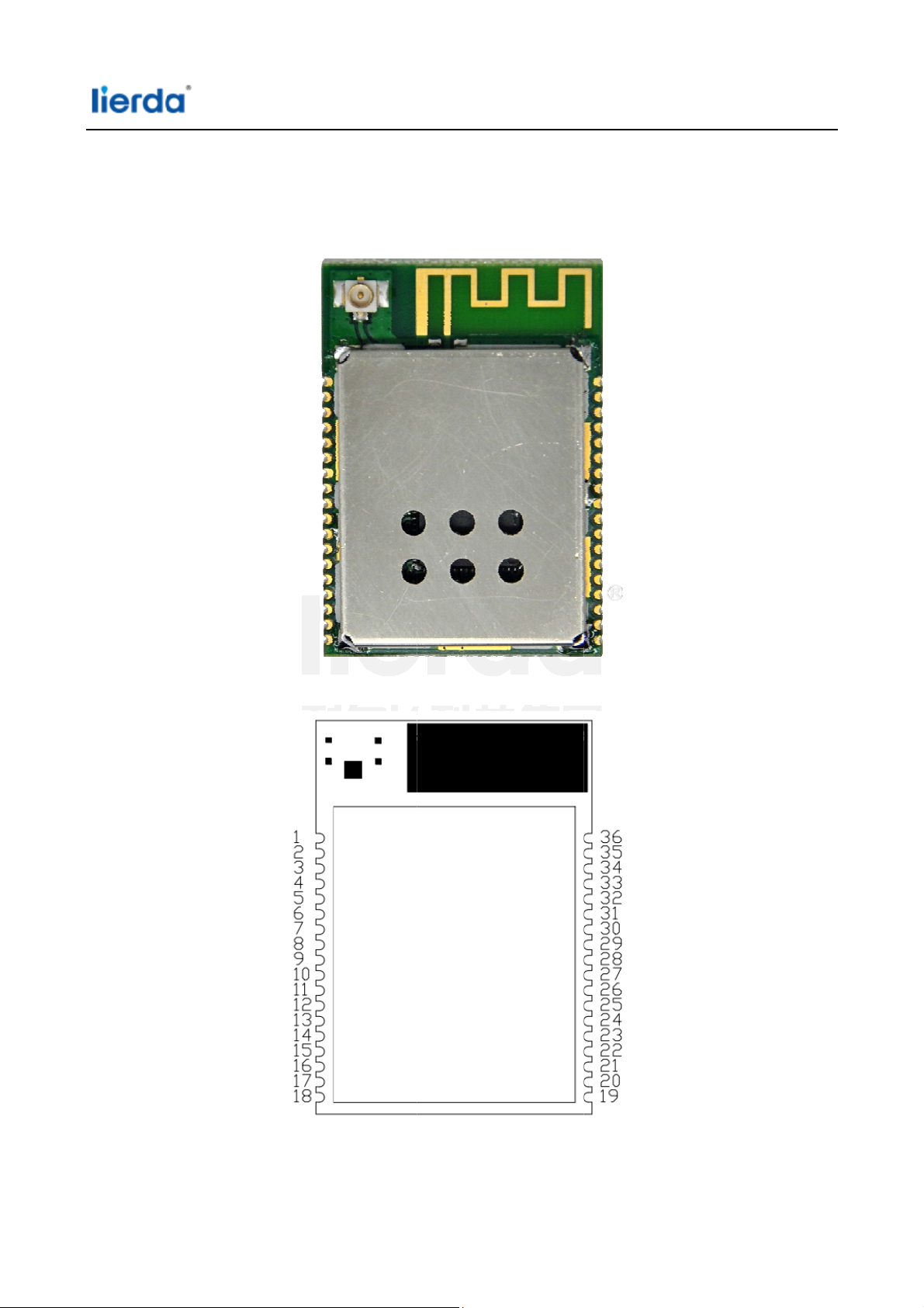
2.1 A
ware
pearan
vervie
ce
2.2 P
oduct s
tructur
size
Address: Li
rda Building,
425 Dengyun
Road, Hangz
hou, China Tel:05
1-88800000 Fax:0571-89908080
Page 5
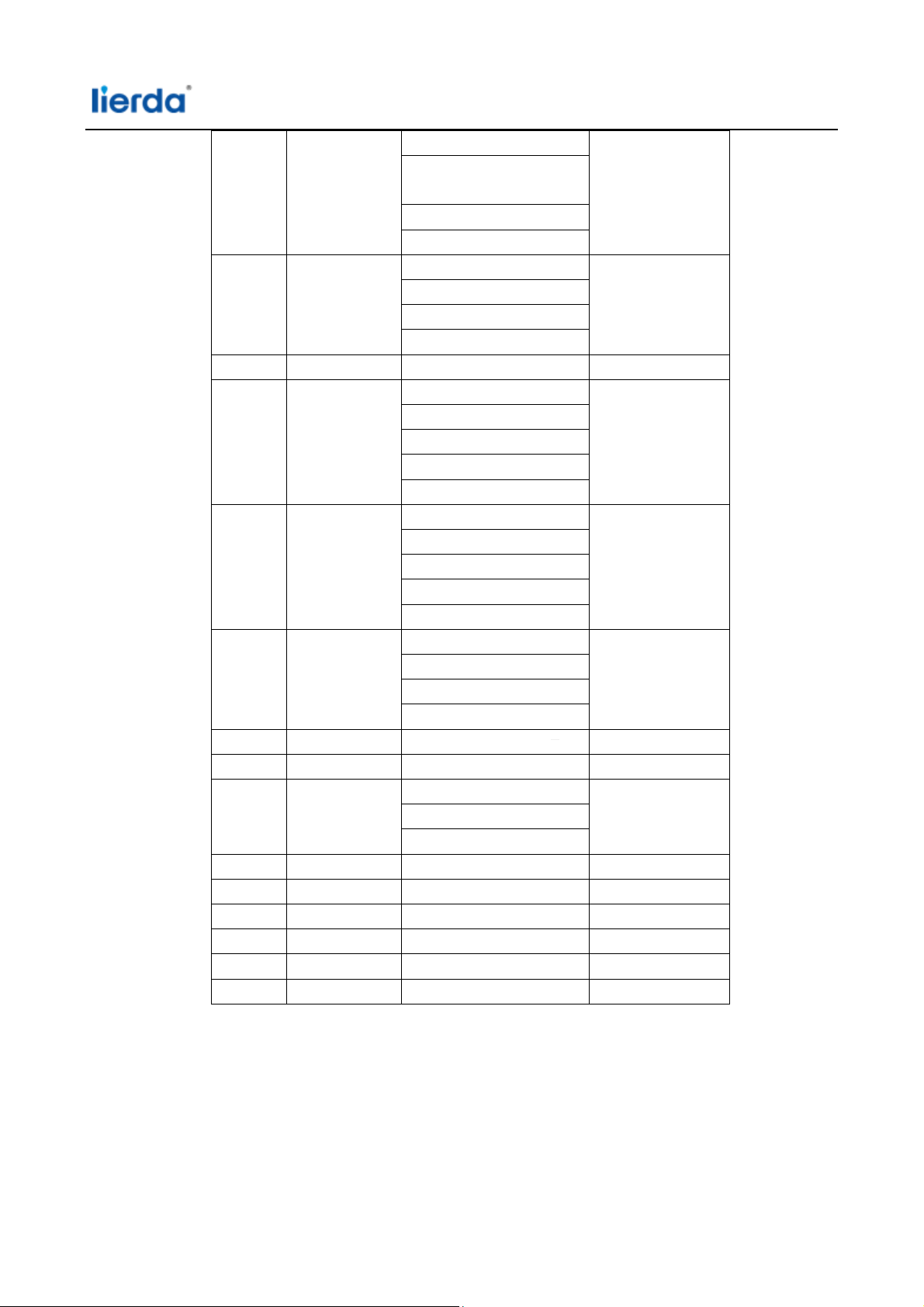
2.3 Distribution Pin Description
NO. Network label Distribution Remark
1 GND GND
2 EXRESET The external reset pin
3 SOP2 Sense-On-Power 2
4 SOP0 Sense-On-Power 0
5 VDD 3.3V
6 VDD 3.3V
7 GND GND
8 GND GND
9 GPIO30 General-PurposeI/O
UART0 TX Data
I2S Audio PortClock O
I2S Audio PortFrame Sync
Timer CapturePort
General SPIMISO
10 GPIO0 General-PurposeI/O
UART0 Clear ToSe nd
Input
I2S Audio PortData 1
(RX/TX)
Address: Lierda Building, 425 Dengyun Road, Hangzhou, China Tel:0571-88800000 Fax: 0571- 89908080
3
Page 6
Timer CapturePort
General SPI ChipPort
General SPI ChipSelect
UART1 RequestTo Send O
UART0 RequestTo Send O
I2S Audio PortData 0
(RX/TX)
11 GPIO6 General-PurposeI/O
UART0 RequestTo Send O
Parallel CameraData Bit 0
UART1 Clear ToSe nd
Input
UART0 Clear ToSe nd
Input
Timer Capture Port
12 GPIO1 General-Purpose I/O
UART0 TX Data
Pixel Clock FromParallel
CameraSensor
UART1 TX Data
Timer CapturePort
13 GPIO2 General-Purpose I/O
UART0 RX Data
UART1 RX Data
Timer CapturePort2
ADC Channel 0Input
(1.5V max)
14 GPIO3 General-Purpose I/O
Parallel CameraData Bit 3
UART1 TX Data
ADC Channel 1Input
(1.5V max)
15 GPIO4 General-Purpose I/O
UART1 RX Data
Parallel CameraData Bit 2
ADC Channel 2 Input
(1.5V max)
16 GPIO5 General-Purpose I/O
Parallel CameraData Bit 1
I2S Audio PortData 1
(RX/TX)
Address: Lierda Building, 425 Dengyun Road, Hangzhou, China Tel:0571-88800000 Fax: 0571- 89908080
4
Page 7
Timer CapturePort 5
ADC Channel 3 Input
(1.5V max)
17 GPIO7 General-Purpose I/O
UART1 RequestTo Send O
UART0 RequestTo Send O
UART0 TX Data
I2S Audio PortClock O
18 GPIO8 General-Purpose I/O
Interrupt from SDCard
(Futuresupport)
I2S Audio PortFrame Sync
Timer Capture Port 6
19 GPIO9 General-Purpose I/O
Pulse WidthModulated05
SD Cad Data
I2S Audio PortData
(Rx/Tx)
Timer CapturePort 0
20 GPIO10 General-Purpose I/O
I2C Clock
Pulse-WidthModulated06
UART1 TX Data
SD Card Clock
Timer CapturePort 1
21 GPIO11 General-Purpose I/O
I2C Data
Pulse-WidthModulated07
Free Clock ToParallel
Camera
SD CardCommand Line
UART RX Data
Timer Capture Port2
I2S Audio PortFrame Sync
22 GPIO12 General-Purpose I/O
I2S Audio PortClock O
Parallel CameraVertical
Sync
I2C Clock
UART0 TX Data
Timer CapturePort 3
23 GPIO13 General-Purpose I/O
Address: Lierda Building, 425 Dengyun Road, Hangzhou, China Tel:0571-88800000 Fax: 0571- 89908080
5
Page 8
I2C Data
Parallel
CameraHorizontal Sync
UART0 RX Data
Timer CapturePort 4
24 GPIO14 General-Purpose I/O
I2C Clock
General SPIClock
Parallel CameraData Bit 4
Timer CapturePort 5
25 GPIO15 General-Purpose I/O
General SPIMISO
I2C Data
Parallel CameraData Bit 5
Timer CapturePort 6
26 GPIO16 General-Purpose I/O
General SPIMOSI
Parallel CameraData Bit 6
UART1 TX Data
Timer CapturePort 7
27 GPIO17 General-Purpose I/O
UART1 RX Data
General SPI ChipSelect
Parallel CameraData Bit 7
28 GND GND
29 VCC 3.3V
30 GPIO22 General-Purpose I/O
I2S Audio PortFrame Sync
Timer Capture Port 4
31 GPIO28 General-Purpose I/O
32 JTAG_TDI JTAG TDI
33 JTAG_TDO JTAG TDO
34 JTAG_TCK JTAG TCK
35 JTAG_TMS JTAG TMS
36 GND GND
3 Functional Description
3.1 Networking features
LSD4WF-3211I5SAmodule canbe configured toAPmodeandSTAmode, atthesame timehavea wireless network
interface, but also includes some commonwired interfacemethods, such asSPIinterface, I2C interface, I2S
interface, UARTinterface; the presenceof these interfacesgreatly expandedconnectionmodule, but also toenable
Address: Lierda Building, 425 Dengyun Road, Hangzhou, China Tel:0571-88800000 Fax: 0571- 89908080
6
Page 9
a user tomore quicklyand modulesfor docking, to achievedata transmissionnetwork;
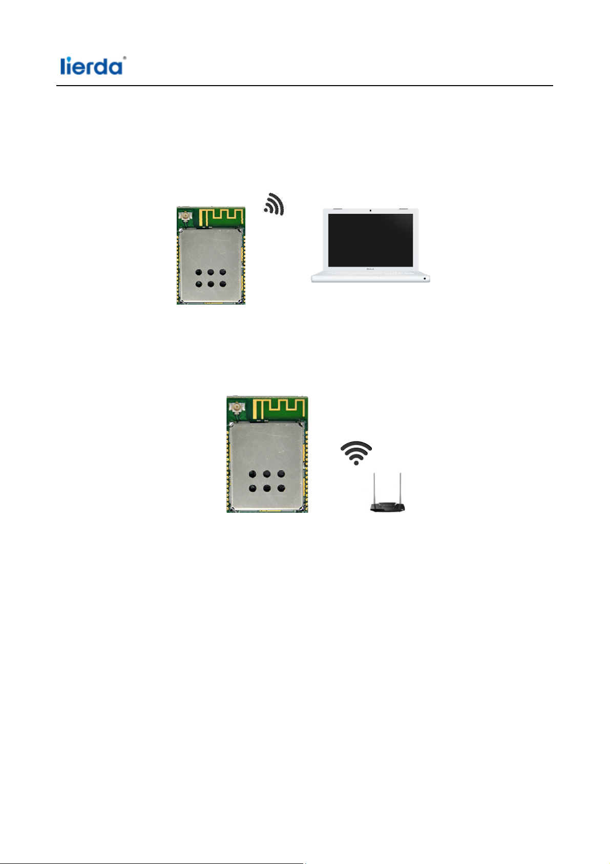
3.1.1 APNetworking
APthe wireless access pointis the center ofanetwork; Generally, the router asAP,undercertain
circumstances,alsosomemobilephoneterminals, PAD asAP; LSD4WFmodulecan also beused asAP mode, for
receivingthe network.Connectionsas shown below:
3.1.2 APNetworking
STAis thewirelessstation, awireless networkterminal, typicallytoaccesstothe AP, the AP transmitsdatato the
networkvia; LSD4WF as the nextSTAmode, can beconnectedwith anyofthe AP, thewireless Internetmoduleto
achieve.
3.2 Passthroughmode
LSD4WFsupports serialtransparent transmissionmode, data from theserial transmissioncabletotransmita
wireless network; transparent transmissionmode,so thatthe customer'sproducts tothe fastest andeasiest way to
implementthe network. Usersneed onlya simple configurationvia the serial portcanbe networkedand data
transmission;
4 Instructions for use
WIFImodulewhen using theneed to usetwo software;
1, SecureCRTserial debugging tools;
2, TCP Socketcommunication tools;
4.1 Network Connection
Configuration moduleinSTAmode, andletthe routerconnection; computerand routerconnection; moduleand
a computerviaa serial connection;
Address: Lierda Building, 425 Dengyun Road, Hangzhou, China Tel:0571-88800000 Fax: 0571- 89908080
7
Page 10
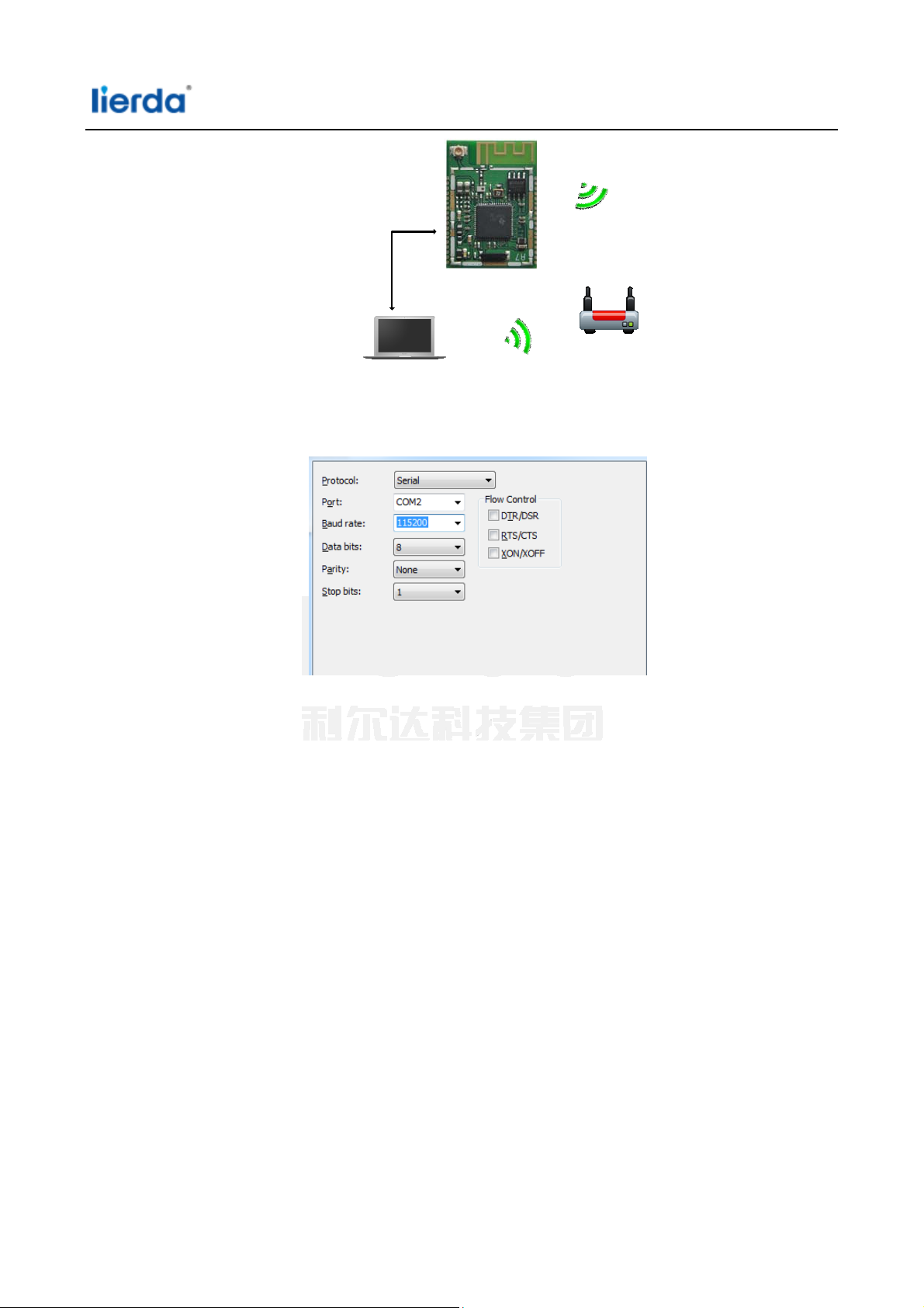
串口连接
4.1.1 SerialPortConfiguration
Openserial debugging assistant, a baud rate of115200,1stop bit, no parity, as follows:
Press therese
canreceiveATcommandsinput;
EnterAT + WKEY = AT + WSKEY = WPAPSK, AES, lierda18f <CR>,return+ ok,whichWPAPSKsecuritytype, AES
dataencryption, lierda18f secret keyforencryption;
EnterAT + WSSID = Lierda18f <CR>,return+ ok;
t buttonmodule, wait for some time, after theinitializationis complete,you
4.2 CreatingSocket
4.2.1 CreatingaSocketA
Opensokittool, selectthe servermode, TCP address is192.168.1.145,port number5001, click theTCP listener,
configuredas follows:
Address: Lierda Building, 425 Dengyun Road, Hangzhou, China Tel:0571-88800000 Fax: 0571- 89908080
8
Page 11

Serial port, enter AT + NETP = TCP, CLIENT, 5001,192.168.1.145 <CR>,return+ ok;
EnterAT + TCPDIS = on <CR>,return+ ok;
Insokittool,a message appearsas follows:
Appear[TCP] 192.168.1.121:64191expressedsokitcreated successfully;
Click to select[TCP] 192.168.1.121:64191,then fillin thesendingareasokittooldataneeds to be sent, and click
Send,receiveserialdatasent successfully, as follows:
Serial dataobtainedare as follows:
4.2.2 CreatingaSocketB
Opensokittool again, chooseserver mode, TCP address is192.168.1.145,the portis set to5002, click theTCP
listener, as follows:
Serial port, enter AT + SOCKB = TCP, 5002,192.168.1.145 <CR>,return+ ok
Enter AT+TCP DISB = on< C R>,return +ok;
Information shown below appears in sokit tool, indicates socketB created successfully, as follows:
Address: Lierda Building, 425 Dengyun Road, Hangzhou, China Tel:0571-88800000 Fax: 0571- 89908080
9
Page 12

Andcreate the firstSocket Communicationsasanareato fillin the datatransmitted bythe data, such
as1234567890, click send, receive dataappearinthe serial, as follows:
Theserial datais as follows:
4.2.3 PassthroughMode
Enter theserial portof theAT + ENTM <CR>,so that the moduleinto thetransparent mode.
5 Warning
This device complies with part 15 of the FCC Rules. Operation is subject to the following two conditions: (1)
(1) This device may not cause harmful interference, and
(2) This device must accept any interference received, including interference that may cause undesired operation.
Changes or modifications not expressly approved by the party
user's authority to operate the equipment.
To satisfy FCC RF Exposure requirements for this transmission devices, a separation distance of 20 cm or
more should be maintained between the antenna of this device and persons during operation. To ensure
compliance, operation at closer than this distance is not recommended. The antenna(s) used for this
transmitter must not be co-located or operating in conjunction with any other antenna or transmitter.
The modular transmitter must be equipped with either a permanently affixed label or must be capable of
electronically displaying its FCC identification number:
(A) If using a permanently affixed label, the modular transmitter must be labeled with its own FCC identification
number, and, if the FCC identification number is not visible when the module is installed inside another device,
then the outside of the device into which the module is installed must also display a label referring to the
enclosed module. This exterior label can use wording such as the following: “Contains Transmitter Module
FCC ID: N8NLSD4WF-CC3221.” Any similar wording that expresses the same meaning may be used. The Grantee
may either provide such a label, an example of which must be included in the application for equipment
authorization, or, must provide adequate instructions along with the module which explain this requirement. In
the latter case, a copy of these instructions must be included in the application for equipment authorization
responsible for compliance could void the
Address: Lierda Building, 425 Dengyun Road, Hangzhou, China Tel:0571-88800000 Fax: 0571- 89908080
10
 Loading...