

Liebherr UR500, UB501, UF501 Installation Manual
Installation
Instructions
Refrigerators and freezers for
integrated use, door-on-door
UR 500 UF 501 UB 501
060418 7086652 - 00
General safety information
Contents
1 General safety information........................... 2
2 Transporting the appliance........................... 2
3 Setting up the device..................................... 2
3 Appliance dimensions................................... 4
5 Recess dimensions....................................... 4
6 Cabinet door................................................... 4
7 Reversing the door........................................ 5
8 Installing the appliance in the recess.......... 8
9 Installation...................................................... 8
9.1 Assembling the appliance................................ 9
9.2 Installing the unit door...................................... 11
10.2 Disposal of packaging...................................... 13
11 Connecting the appliance............................. 13
Congratulations on the purchase of your new appliance.
With this purchase, you have chosen all the advantages of
the latest refrigeration technology, guaranteeing you a
high-quality appliance with a long life span and high operating safety.
The equipment of your appliance gives you the highest
level of day-to-day ease of operation.
Together we are making an active contribution to the
conservation of our environment by purchasing this appliance which is manufactured in an environmentally friendly
process with the use of recyclable materials.
We hope you enjoy your new appliance.
The manufacturer is constantly working to improve all
models. Therefore please understand that we reserve the
right to make design, equipment and technical modifications.
To get to know all the benefits of your new appliance,
please read the information contained in these instructions carefully.
The instructions apply to several models, so there may be
differences. Sections which only apply to certain appliances are indicated with an asterisk (*).
Instructions for action are marked with a
results of action are marked with a .
, the
1 General safety information
-
Read and follow these instructions. They
contain safety advice which is important for
safe and problem-free installation and operation. Always read and follow the safety advice.
-
It is important that the guidelines and instructions in this manual are followed so that the
appliance is correctly installed and operates
properly Read and understand all information
in this manual before the appliance is installed
-
Risk of asphyxiation and crushing:
Remove doors and shelves from old appliances to prevent them from becoming a potential hazard to children at play.
-
Only install, connect and dispose of the appliance in accordance with the instructions. Pay
particular attention to “niche dimensions” and
“ventilation and fume extraction in kitchen
units”.
-
The socket must be easily accessible so that
the appliance can be disconnected from the
mains quickly in an emergency. It must not be
behind the back of the appliance.
DANGER indicates a hazardous situation,
which if not avoided, will result in
death or serious injury.
WARNING indicates a hazardous situation,
which if not avoided, could result in
death or serious injury.
CAUTION indicates a hazardous situation,
which if not avoided, will result in
minor or moderate injury.
NOTICE indicates a hazardous situation,
which if not avoided, could result in
damage to property.
Note indicates useful advice and tips.
2 Transporting the appliance
CAUTION
Risk of injury or damage if incorrectly transported.
Transport the appliance in its packaging.
u
Transport the appliance upright.
u
Do not move the appliance on your own.
u
3 Setting up the device
WARNING
Risk of fire due to short circuit.
If the power cable or plug of the appliance or another
appliance and the back of the appliance touch each other
the power cable or plug will be damaged by the vibrations
of the appliance which could lead to a short circuit.
Install the appliance so that it does not touch any plugs
u
or power cables.
Do not connect the appliance or other appliances to the
u
sockets on the back of the appliance.
2 * Depending on model and options
WARNING
Risk of fire due to moisture!
If live parts or the power cord get wet, this can cause a
short circuit.
The appliance is designed for use in enclosed spaces.
u
Do not operate the appliance in open space or in damp
areas or where there is spray.
Only operate the appliance after it has been installed.
u
WARNING
Risk of fire due to refrigerant.
The refrigerant contained within the appliance, R 600a, is
environmentally friendly, but flammable. Leaking refrigerant can ignite.
Do not damage the pipes of the refrigerant circuit.
u
WARNING
Danger of fire and damage!
Do not place devices that give off heat, e.g. micro-
u
waves, toasters, etc. on the appliance.
NOTICE
Risk of damage caused by condensation
Installing the appliance next to any other refrigerator or
freezer can cause condensation or damage to the Liebherr appliance.
Do not install this appliance next to any other refriger-
u
ator or freezer except another Liebherr model. Liebherr
models are designed to allow side-by-side installation.
They are equipped with a heating system to eliminate
condensation when refrigerators or freezers are
installed side-by-side.
NOTICE
Risk of damage for the finished floor surface!
Protect the finished floor surface before you uncrate the
u
unit.
WARNING
Danger of damage from overheating. May restrict operation.
Keep ventilation openings, in the appliance enclosure
u
or in the built-in structure, clear of obstruction.
Setting up the device
The floor of the installation site must be horizontal and
q
level.
Do not install the appliance in direct sunlight or next to
q
an oven, heater or similar heat source.
Do not install the appliance on your own. It is better to
q
do this with two or more people.
The more R 600a refrigerant is in the appliance, the
q
larger the room must be where the device is located. In
the case of a leak, a flammable gas-air mixture may be
created in a room that is too small. In accordance with
standard EN 378, for every 0.39 oz (11 g) R 600a
coolant, the installation space must be at least35.5 ft
(1 m3). The amount of refrigerant in your appliance is
indicated on the identification plate inside the appliance.
If the appliance is installed in a very damp environment
q
condensate water may form on the outside of the appliance. Always ensure good ventilation.
The load-bearing capacity of the floor must be sufficient
q
for the weight of the appliance plus about 1200 pounds
(544 kg) of food weight.
The electrical socket must assessed precisely to
q
ensure the correct position and fuse.
Do not restrict ventilation. Sufficient ventilation is
q
required for the appliance to operate correctly. The
ventilation grid fitted at the factory guarantees an effective ventilation gap on the appliance of 31 in.
(200 cm2). If you replace the ventilation grid with a
fascia, this must have at least the same size or larger
ventilation gap as the manufacturer's ventilation grid.
Note down the type (model, number), appliance name,
u
appliance or serial number, date of purchase and
manufacturer's address in the place provided for this in
the Use & Care Manual.
Remove all materials that could prevent it from being
u
installed properly or prevent proper ventilation from the
back or the side panels of the appliance.
After installation:
Remove protective films, adhesive tapes and transport
u
safety devices, etc.
Note
Clean the appliance (see operating instructions,
u
"Cleaning the appliance" section).
3
2
WARNING
Danger of tilting.
To avoid a hazard due to instability of the appliance, it
u
must be fixed in accordance with the instructions.
If possible, have a professional install the appliance in
q
your kitchen cabinet unit.
If the appliance is damaged check with the supplier
q
immediately before connecting it.
* Depending on model and options 3
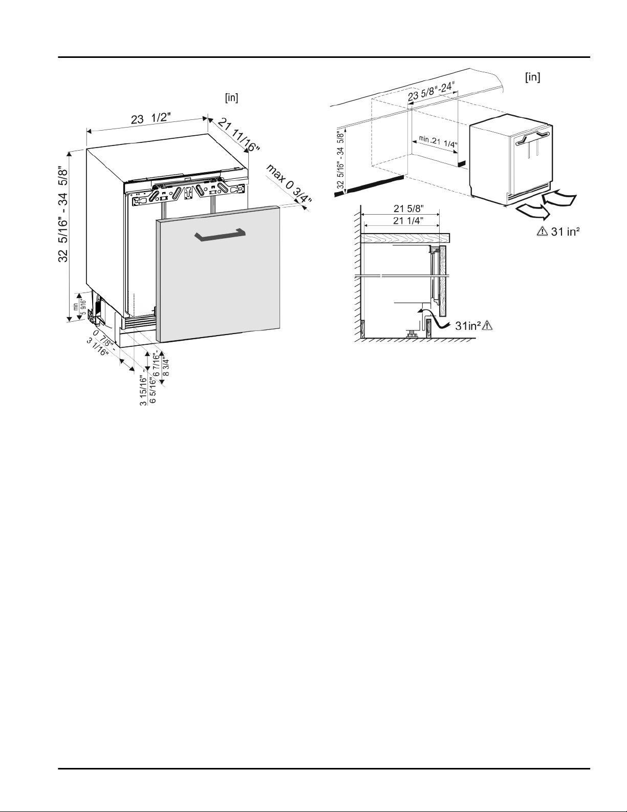
Appliance dimensions
3 Appliance dimensions
Fig. 1
5 Recess dimensions
This is an under-worktop appliance and is installed below
the worktop. The kitchen cabinet surrounding the appliance must be designed exactly in accordance with the
specified dimensions and must allow sufficient air circulation to ensure correct operation of the appliance.
Fig. 2
The declared energy consumption was determined with a
kitchen cabinet depth of 560 mm. The appliance is fully
functional with a kitchen cabinet depth of 550 mm but will
have a slightly increased level of energy consumption.
Check the wall thickness of adjacent cabinets: It must
u
be at least 5/8 in. (16 mm).
Align the cabinets with a spirit level and a try square. If
u
necessary level them by putting something underneath
them.
Ensure that the floor and the side panels of the cabinet
u
are at right angles to each other.
6 Cabinet door
A door is required for the kitchen cabinet.
The door must be at least 5/8 in. (16 mm) and no more
than 3/4 in. (19 mm) thick.
There must be a gap of at least 1/8 in. (3 mm) between
the door and the cupboard door above it (if there is
one).
The width of the cabinet door depends on the style of
the kitchen and the size of the gap between the door
panels of the cupboard. Normally a vertical gap of
1/8 in. (3 mm) should be left between the cabinet
doors.
If there are other cabinets the top edge of the cabinet
door should be at the same height as the doors on the
adjacent cabinets.
The cabinet door must be assembled flat and free from
tension.
4 * Depending on model and options
NOTICE
An excessively heavy unit door can cause potential
damage!
If the unit door is too heavy, we cannot rule out damage to
the hinges, which may compromise the use of the unit.
Before installing the unit door, ensure the door does not
u
exceed the permissible weight.
Appliance type Maximum weight of
unit door
UR 500 / UF 501 / UB 501 22 lbs (10 kg)
Reversing the door
Fig. 4
7 Reversing the door
WARNING
Risk of bodily injury due to the door falling off.
If the fasteners are not installed with the proper torque, the
door may fall off. In addition, the door may not close, thus
impairing the cooling performance of the appliance.
Tightly secure the hinges along ball stud of the soft
u
stop mechanism by applying a torque of 3 lb-ft (4 Nm).
Tighten the soft stop mechanism retainer firmly with
u
2.5 lb-ft (3 Nm).
Check all screws and retighten if necessary.
u
Note
The door stop can only be changed if there is sufficient
space above to remove the hinge fixing bracket and fit it
on the opposite side again. This is not normally the case
when installing in a recess.
Change the door stop before the appliance is installed
u
in the recess.
There is the risk of injury when doing this. Obey the
safety instructions.
The instructions apply to several models. Only perform
this step if it applies to your appliance.
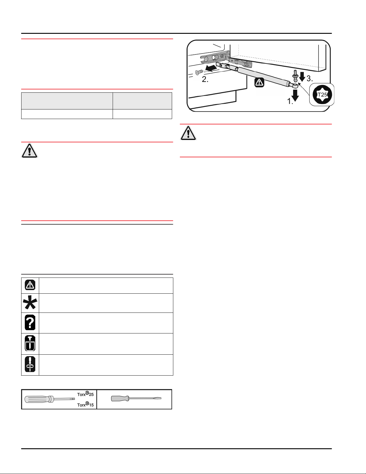
CAUTION
Risk of injury if soft stop contracts!
Carefully remove soft stop damper.
u
Removing the soft stop damper: Remove the soft stop
u
damper from the ball stud (1). Unscrew the retainer (2).
Remove the ball stud with a screwdriver (3).
Select one of the alternatives shown.
Only undo the screw. Don't take it out.
Check the screws and if necessary tighten them.
Required tool:
Fig. 3
* Depending on model and options 5
 Loading...