

Liebherr UPR503 Owners Manual
Instructions
for use and
installation
Instrucciones
de uso y
montaje
Frigorífico empotrable bajo
encimera, Cajón extraíble
Instructions
d'utilisation et
de montage
Réfrigérateur encastrable sous
plan, Tiroir coulissant
UPR 503
270416 7086454 - 00
The appliance at a glance
Contents
1 The appliance at a glance............................. 2
1.1 Additional benefits............................................ 2
1.2 Overview of the appliance and accessories..... 2
1.3 Range of appliance use.................................... 3
1.4 Conformity........................................................ 3
1.5 Energy saving................................................... 3
2 General safety information........................... 3
3 Controls and displays................................... 4
3.1 Operating and control elements....................... 4
3.2 Temperature display......................................... 4
4 Start-up........................................................... 5
4.1 Transporting the appliance............................... 5
4.2 Setting up the device........................................ 5
4.3 Installation........................................................ 6
4.4 Adjust the fit of the door seal............................ 11
4.5 Disposal of packaging...................................... 12
4.6 Connecting the appliance................................. 12
4.7 Switching the appliance on............................... 13
5 Operation........................................................ 13
5.1 Refrigerating food............................................. 13
5.2 Setting the temperature.................................... 13
5.3 SuperCool........................................................ 13
5.4 Moving the supporting bars.............................. 13
5.5 Dividing the vegetable drawer.......................... 14
5.6 Storing in the floor recess................................. 14
6 Maintenance................................................... 14
6.1 Thawing........................................................... 14
6.2 Cleaning the appliance..................................... 14
6.3 Customer service............................................. 15
6.4 Appliance Information...................................... 16
7 Troubleshooting............................................. 16
8 Putting appliance out of service.................. 18
8.1 Vacation Tips.................................................... 18
8.2 Switching the device off.................................... 18
8.3 Decommissioning ............................................ 18
9 Disposing of the appliance........................... 18
10 Liebherr Warranty Plan................................. 18
right to make design, equipment and technical modifications.
To get to know all the benefits of your new appliance,
please read the information contained in these instructions carefully.
The instructions apply to several models, so there may be
differences. Sections which only apply to certain appliances are indicated with an asterisk (*).
Instructions for action are marked with a , the
results of action are marked with a .
1 The appliance at a glance
1.1 Additional benefits
Large refrigeration capacity
Bright LED interior light
Integrated transport grips on appliance housing
Easy to clean
-
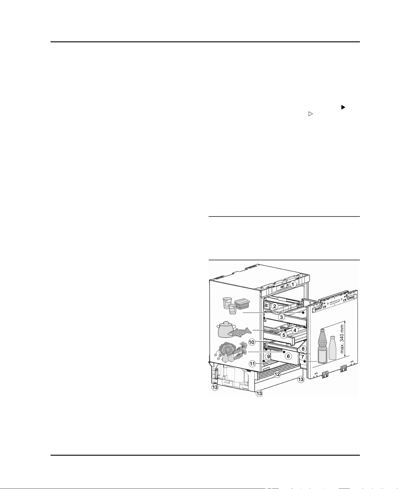
1.2 Overview of the appliance and
accessories
Note
Arrange food as shown in the picture. This arrangement
u
allows the appliance to work more efficiently, thus
saving energy.
Shelves, drawers, and baskets are arranged for optimal
u
energy efficiency in the factory configuration.
Congratulations on the purchase of your new appliance.
With this purchase, you have chosen all the advantages of
the latest refrigeration technology, guaranteeing you a
high-quality appliance with a long life span and high operating safety.
The equipment of your appliance gives you the highest
level of day-to-day ease of operation.
Together we are making an active contribution to the
conservation of our environment by purchasing this appliance which is manufactured in an environmentally friendly
process with the use of recyclable materials.
We hope you enjoy your new appliance.
The manufacturer is constantly working to improve all
models. Therefore please understand that we reserve the
2 * Depending on model and options
Fig. 1
(1) Control panel (8) Adjustable door
(2) Interior light* (9) Storage space in the
floor recess
(3) Pull-out rack (10)Defrost drain
(4) Adjustable supporting
bars
(11)Rating plate
General safety information
(5) Pull-out rack, coldest
zone
(6) Vegetable drawer (13)Front and rear adjusting
(7) Bottle shelf
(12)Adjustable plinth panel
feet
1.3 Range of appliance use
Normal use
The appliance is only suitable for cooling food for
residential or other similar environments. This
includes the following types of uses
-
in staff kitchens, bed and breakfasts,
-
by guests in country homes, hotels, motels
and other types of accommodations,
-
for catering and similar wholesale services.
The appliance is suitable for integrated under
worktop use
All other types of uses are not permitted.
Foreseeable misuse
The following uses are specifically prohibited:
-
Storage and cooling of medication, blood
plasma, laboratory preparations or similar
substances and products in accordance with
the CMDCAS and FDA 510(k)
-
Use outdoors.
-
Use in moist areas exposed to the rain.
-
Use in areas at risk of explosion
Incorrect appliance use can cause damage to
the stored products or cause them to spoil.
Climate ratings
The appliance is set to operate within specific
ambient temperature limits according to its
climate rating The climate rating for your appliance is printed on the rating plate
Note
To guarantee trouble-free operation, comply
u
with the indicated ambient temperatures.
Climate
rating
SN 50 °F (10 °C) to 90 °F (32 °C)
N 61 °F (16 °C) to 90 °F (32 °C)
ST 61 °F (16 °C) to 101 °F (38 °C)
T 61 °F (16 °C) to 110 °F (43 °C)
for ambient temperatures from
1.4 Conformity
The refrigerant circuit has been tested for leaks. When
installed, the appliance complies with the relevant safety
regulations and the safety standards CAN/CSA-C22.2 No.
60335-1-11, 60335-2-24-06 and UL 60335-1, UL
60335-2-24.
1.5 Energy saving
Always ensure good ventilation. Do not obstruct ventila-
tion openings or grilles.
Do not install the appliance in direct sunlight or next to
an oven, heater, or similar heat source.
Energy consumption depends on installation conditions
such as the ambient temperature (see 1.3) . If the
ambient temperature differs from the standard temperature of 25 °C, energy consumption can change.
Avoid opening the appliance door for any longer then
necessary
The lower the temperature is set the higher the energy
consumption.
Store food logically (see The appliance at a glance).
All food stored in the appliance should be well wrapped
and covered. This prevents frost buildup.
Only take food out for as long as necessary so that it
does not get too warm.
Insertion of warm foods: first let the food cool down to
room temperature.
2 General safety information
Read and follow these instructions. They contain
safety advice which is important for safe and
problem-free installation and operation. Always
read and follow the safety advice.
Dangers for the user:
-
This appliance can be operated by children 8
years and older as well as by persons with
reduced physical, sensory or mental capabilities or lack of experience and knowledge if
they are supervised or have been instructed in
the safe use of the appliance and understand
the associated risks. Children must not play
with the appliance. Cleaning and user maintenance must not be performed by children
unless they are supervised.
-
When disconnecting the appliance from the
outlet, always take hold of the plug. Do not pull
on the cable.
-
Disconnect the power plug or switch off the
power if a fault occurs.
-
Do not damage the mains power line. Do not
operate the appliance from a defective mains
power line.
-
Repairs, work on the appliance and replacement of the power cord should only be carried
out by the customer service department.
* Depending on model and options 3
Controls and displays
-
Only install, connect and dispose of the appliance in accordance with the instructions.
-
Only operate the appliance after it has been
installed.
-
Please keep the instructions and pass them on
to any future owner.
-
Special-purpose lamps inside the appliance
are intended to illuminate its interior compartments and are unsuitable for room illumination.
Risk of fire:
-
Do not operate the appliance near explosive
gases.
-
Do not store or use gasoline or other flammable vapors and liquids in the vicinity of this
appliance.
-
Do not store explosive materials or spray cans
with flammable propellants, such as e.g.
butane, propane, pentane, etc. in the appliance. You can recognize such spray cans by
the printed contents or a flame symbol. Any
leaking gasses can be ignited by electrical
components.
-
Alcoholic beverages or other containers
holding alcohol must always be tightly sealed
for storage purposes. Any leaking alcohol can
be ignited by electrical components
Tipover hazard:
-
Do not stand or climb on the base, drawers,
doors, etc. This applies in particular to children.
Risk of food poisoning:
-
Do not consume food that has passed its best
before date.
Danger of frostbite, feelings of numbness
and pain:
-
Avoid continued skin contact with the cold
surfaces or chilled/frozen food or adopt protective measures, e. g. use gloves. Do not
consume ice cream (especially sherbets) and
ice cubes immediately when they are too cold.
Risk of injury and damage:
-
Hot steam may lead to injuries. Do not use any
electrical heating or steam cleaning equipment, naked flames or defrosting sprays for
defrosting
-
Do not remove ice with sharp objects
Risk of crushing:
-
Do not hold onto the hinge when opening and
closing the door. Fingers may get caught.
California Proposition 65
-
This product contains chemicals known to the
state of California to cause cancer or reproductive harm.
Symbols on the device:
The symbol can be on the compressor. It refers to
the oil in the compressor and refers to the following
danger: Can be lethal if swallowed or inhaled. This
notice only applies for recycling. There is no danger
during normal operation.
Follow the specific instructions in the other
sections:
DANGER indicates a hazardous situation,
which if not avoided, will result in
death or serious injury.
WARNING indicates a hazardous situation,
which if not avoided, could result in
death or serious injury.
CAUTION indicates a hazardous situation,
which if not avoided, will result in
minor or moderate injury.
NOTICE indicates a hazardous situation,
which if not avoided, could result in
damage to property.
Note indicates useful advice and tips.
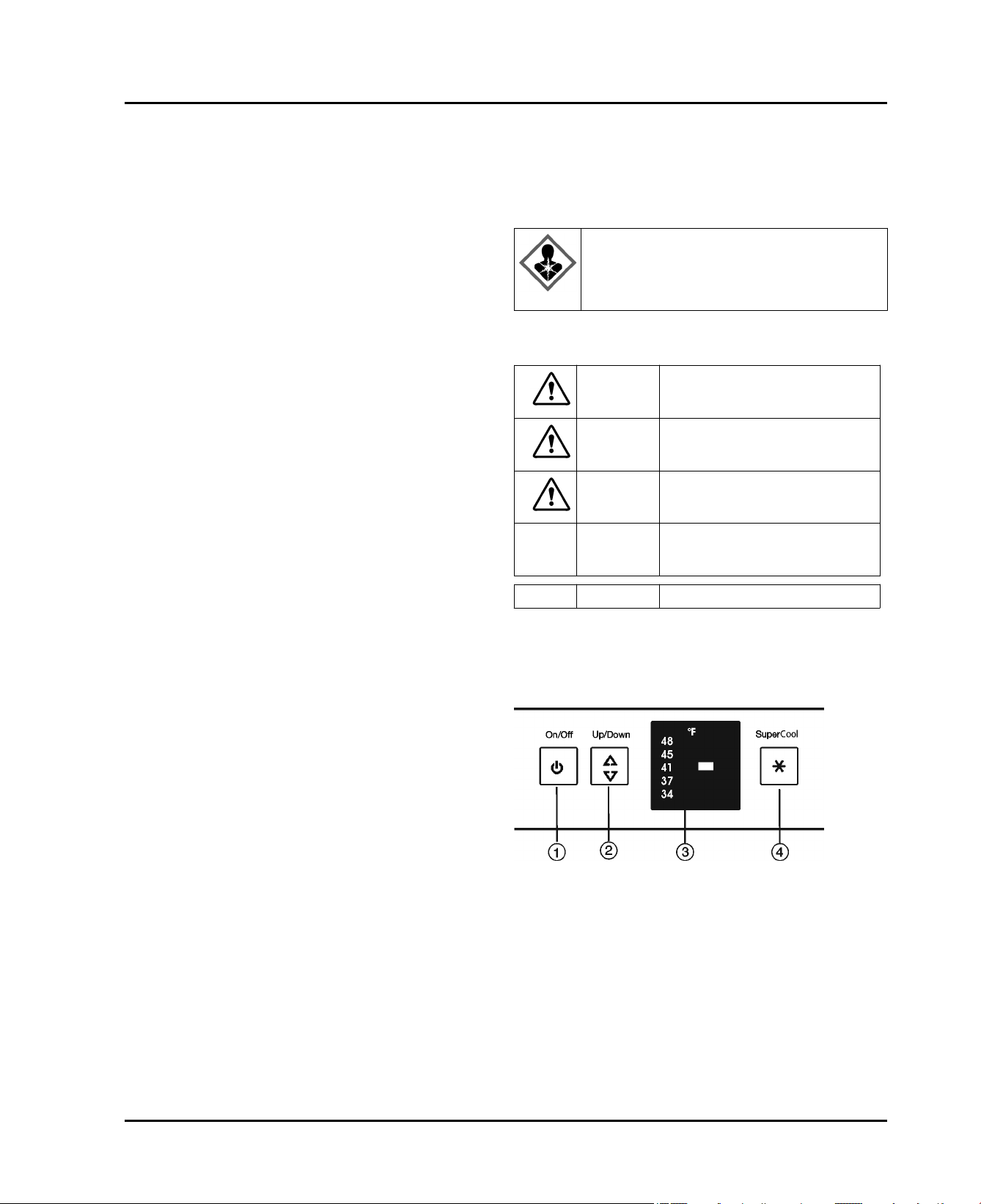
3 Controls and displays
3.1 Operating and control elements
Fig. 2
(1) On/Off button (3) Temperature display
(2) Set button (4) SuperCool button
3.2 Temperature display
The following is displayed in normal operation:
the fridge temperature set
-
4 * Depending on model and options
Start-up
4 Start-up
4.1 Transporting the appliance
CAUTION
Risk of injury or damage if incorrectly transported.
Transport the appliance in its packaging.
u
Transport the appliance upright.
u
Do not move the appliance on your own.
u
4.2 Setting up the device
WARNING
Risk of fire due to short circuit.
If the power cable or plug of the appliance or another
appliance and the back of the appliance touch each other
the power cable or plug will be damaged by the vibrations
of the appliance which could lead to a short circuit.
Install the appliance so that it does not touch any plugs
u
or power cables.
Do not connect the appliance or other appliances to the
u
sockets on the back of the appliance.
WARNING
Risk of fire due to moisture!
If live parts or the power cord get wet, this can cause a
short circuit.
The appliance is designed for use in enclosed spaces.
u
Do not operate the appliance in open space or in damp
areas or where there is spray.
Only operate the appliance after it has been installed.
u
WARNING
Danger of fire and damage!
Do not place devices that give off heat, e.g. micro-
u
waves, toasters, etc. on the appliance.
WARNING
Danger of fire and damage due to blocked ventilation
openings!
Never block the ventilation openings. Always ensure
u
good ventilation!
NOTICE
Risk of damage for the finished floor surface!
Protect the finished floor surface before you uncrate the
u
unit.
WARNING
Danger of damage from overheating. May restrict operation.
Keep ventilation openings, in the appliance enclosure
u
or in the built-in structure, clear of obstruction.
WARNING
Danger of tilting.
To avoid a hazard due to instability of the appliance, it
u
must be fixed in accordance with the instructions.
If possible, have a professional install the appliance in
q
your kitchen cabinet unit.
If the appliance is damaged check with the supplier
q
immediately before connecting it.
The floor of the installation site must be horizontal and
q
level.
Do not install the appliance in direct sunlight or next to
q
an oven, heater, or similar heat source.
This appliance is suitable for integrated under-the-
q
counter installation.
Ventilation is provided through the appliance pedestal.
q
Do not install the appliance without assistance.
q
The load-bearing capacity of the floor must be sufficient
q
for the weight of the appliance plus about 1200 pounds
(544 kg) of food weight.
The electrical socket must assessed precisely to
q
ensure the correct position and fuse.
Note down the type (model, number), appliance name,
u
appliance or serial number, date of purchase and
manufacturer's address in the place provided for this in
the Use & Care Manual.
Remove all materials that could prevent it from being
u
installed properly or prevent proper ventilation from the
back or the side panels of the appliance.
Remove the mains cable from the back of the appli-
u
ance. Also remove the cable holder, otherwise there
will be vibration noise!
After installation:
Remove the protective film from the decorative trims.
u
Remove all transport safety devices.
u
NOTICE
Risk of damage caused by water condensate!
Do not install this device directly beside another fridge/
u
freezer compartment.
* Depending on model and options 5
Start-up
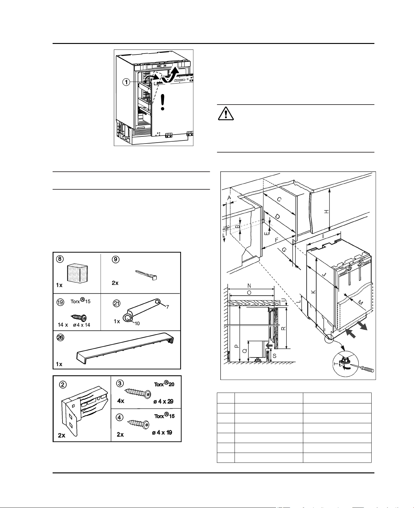
Fig. 3
Swing the transport safety device
u
and remove it from the front.
Dispose of the packaging material. (see 4.5)
u
Note
Clean the appliance (see 6.2) .
u
If the appliance is installed in a very damp environment
condensate water may form on the outside of the appliance.
Always ensure good ventilation.
u
Fig. 3 (1)
to the side
Hex wrench 13
q
Torx® 15 screwdriver
q
Slot screwdriver 6
q
Allen key 8
q
Tape measure
q
Pencil
q
String
q
WARNING
Risk of fire due to short circuit!
When inserting the appliance into the recess do not
u
squash, jam or damage the power cable.
Do not operate the appliance with a faulty power cable.
u
Make sure the electrical sockets can be accessed.
Check the installation dimensions
4.3 Installation
All fasteners are supplied with the appliance.
Make sure you have the following tools on hand:
Cordless screwdriver Torx® 15, 20, 25
q
Fig. 4
Fig. 5
Fig. 6
in. mm
A 3–15/16 100
B 7-7/8 200
C min. 21–5/8 min. 550
D 21-1/4 540
E 5-1/2 140
F 23–5/8 — 24 600 — 610
6 * Depending on model and options
Start-up
G 7/8 — 3 22 — 77
H 32–1/4 — 34–1/4 820 — 870
I 23-1/2 597
J 21-5/8 550
K 32–1/4 — 34–1/4 819.5 — 869.5
L 6-5/8 168
M max. 3/4 max. 19
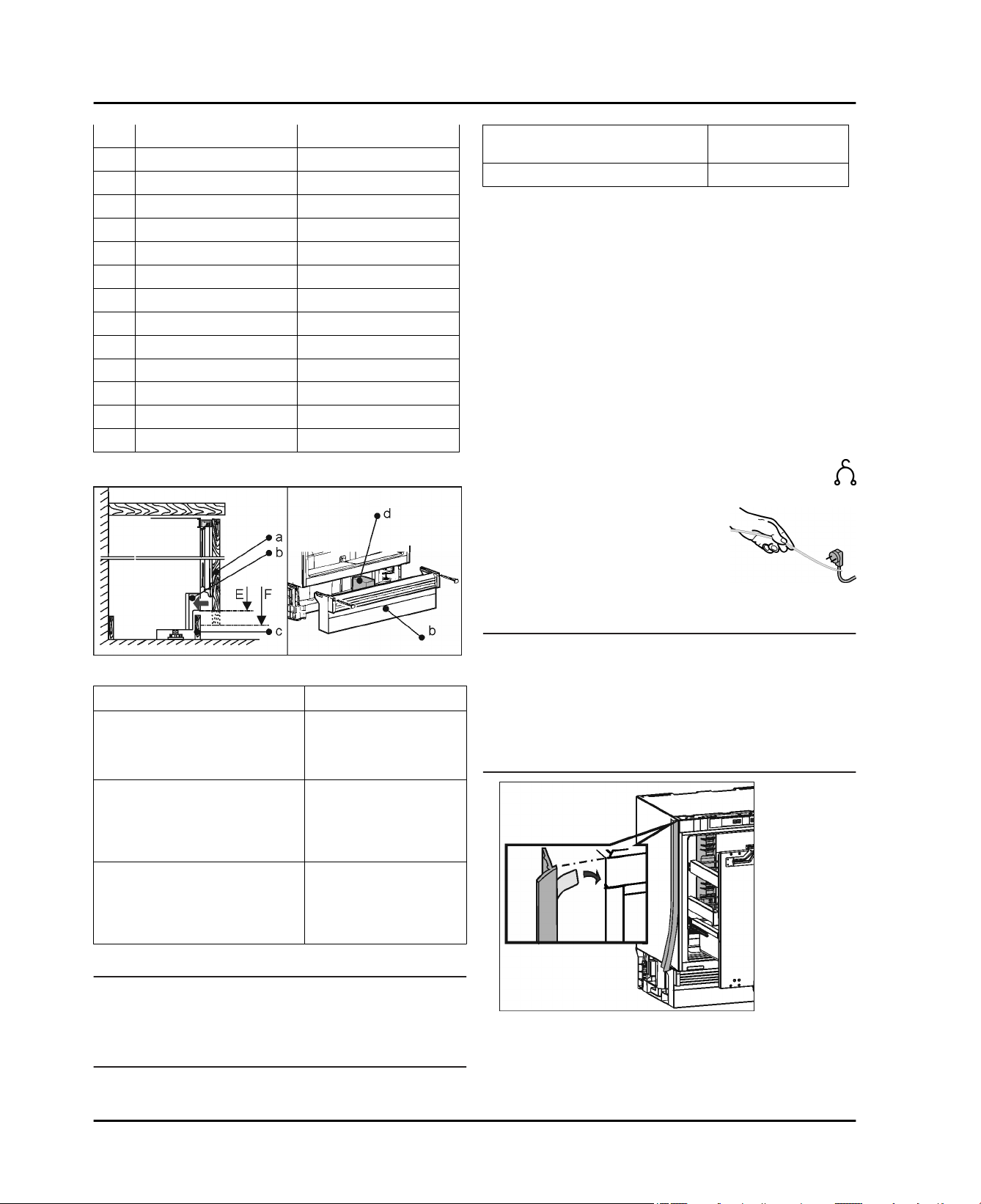
N 21-5/8 550
O 21-1/4 540
P 32–1/4 — 34-5/8 820 — 880
Q 6-5/8 — 8-9/16 168 — 218
R 25-7/16 — 30-5/16 646 — 770
S max. 4 — 6 max. 102 — 152
T max. 2 max. 50
Ventilation requirements
Maximum weight of
Model
UIK 22.05 lbs (10 kg)
unit door
Fastening method on the kitchen cabinet
Side fastening
Installation below hard worktops such as granite.
q
With the adjusting feet completely screwed out, the
q
appliance is lower than the counter top.
Requirement: Cabinet side panel for the screw connec-
q
tion.
Top fastening
When the adjusting feet are screwed out completely,
q
the appliance sits slightly tensioned below the worktop.
No granite top.
q
4.3.1 Assembling the appliance
Removed unit plinth trim.
Remove the mains cable from the back of the
u
appliance. Also remove the cable holder, otherwise there will be vibration noise!
Position the mains cable using
u
a piece of string so that the
appliance can easily be
connected to the electricity
supply after it has been built-in
Insert and align appliance
Fig. 8
Fig. 7
Requirement Effect
Case E: The ventilation openings
in the plinth trim b are freely visible
or are scarcely covered by the unit
door.
Case F: The unit door covers the
ventilation openings in the plinth
trim b and part of the unit plinth
trim c.
Fix the foam element centrally
in the plinth trim b.
Sufficient ventilation.
There must be a ventilation gap of 1-3/8 ''
(35 mm) between the unit
plinth trim and the unit
door.
Foam element d is used to
separate the incoming
and outgoing air currents
and permits sufficient
ventilation.
Weight of the unit door
Note
Before assembling the unit door, make sure that the
u
permitted weight for the unit doors is not exceeded
Otherwise damage to the telescopic rails and malfunc-
u
tions arising from this cannot be ruled out.
NOTICE
Risk of damage to delicate floors!
Place a strip of cardboard under the height-adjustable
u
feet, approx. 4 in.x24 in. ( 10 cm x 60 cm ), one at either
side. Cut the strips out of the packaging. If the recess
heights are smaller than ( 826 mm ) cut the strips out of
a firm but thin material.
After the appliance has been slid in, remove the strips.
u
Fig. 9
With a 23-5/8 '' (600 mm) wide recess: Do not use strips.
With a 24-1/32 '' (610 mm) wide recess: Place the strips
on the side.
* Depending on model and options 7
Start-up
- The appliance is to the right of the adjacent cabinet: Fit
the strip to the left.
- The appliance is to the left of the adjacent cabinet: Fit
the strip to the right.
Place the strip under the top edge and stick it to the
u
side panel. The strip must not be shortened.
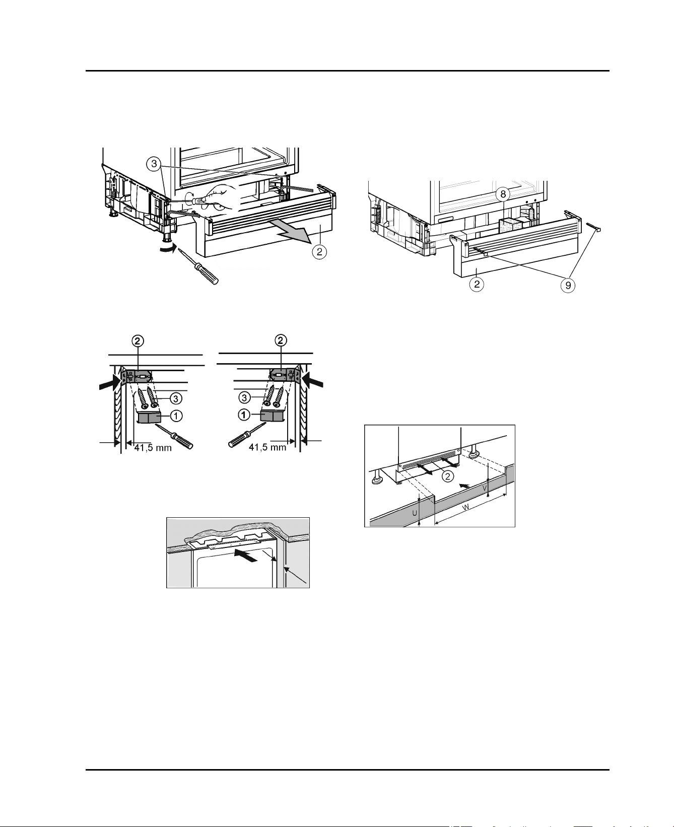
Fig. 10
Remove the plinth trim
u
Fig. 10 (2)
.
Side fastening:
Unscrew the rear adjusting feet
u
Fig. 10 (3)
with a screwdriver and the front adjusting feet with an Allen key 8
(for screwed in adjusting feet) or screwdriver (with
unscrewed adjusting feet) in an alternating manner as
far as possible. The maximum adjustment distance is
1-31/32 '' (50 mm).
The appliance is aligned vertically
w
The appliance is blocked slightly in the recess between
w
the floor and the worktop.
Insert the foam element
u
Fig. 13 (8)
- functionally important for separate air currents!
Reinstall the plinth trim
u
Position the unit door and unit plinth trim for testing
u
If the plinth trim
u
Fig. 13 (2)
Fig. 13 (2)
.
is visible, pull it forward as far
as possible so that the front edge of the ventilation grid
and the unit plinth trim lie flush.
-or-
If the plinth trim
u
Fig. 13 (2)
is covered, push it fully back.
Fig. 13
Fig. 11
Remove the cover
u
Screw in the fixing bracket
u
and left with screws
Fig. 11 (1)
Fig. 11 (2)
Fig. 11 (3)
at the top right and left.
loosely on the right
.
Side and top fastening:
Push the
u
appliance into
the recess.
Unscrew the rear adjusting feet
u
Fig. 10 (3)
with a screwdriver and the front adjusting feet with an Allen key 8 in
an alternating manner until they are just below the
worktop.
Align the appliance vertically.
u
The distance between the front edge of the unit side
w
wall and the appliance itself is 1-5/8 '' (41.5 mm) all
around.
If there is no cabinet side panel, align it with the work
w
top.
In units with door stop components (knobs,
sealing lips, etc.)
Subtract the additional distance (for depth of the door
u
stop components) from the 1-5/8 '' (41.5 mm) insertion
depth.
Fig. 12
Fig. 14
Make sure the ventilation slots are completely unob-
u
structed: If necessary, crop the height of the unit plinth
trim (U)!
Adjust the height of the rack (V) below the appliance
w
plinth trim along the width of the recess (W).
Affix the plinth trim: Keep a steady grip on the plinth
u
trim and insert the latch
Fix the unit plinth trim.
u
Fig. 13 (9)
.
To secure the appliance in the recess
Top fastening:
8 * Depending on model and options
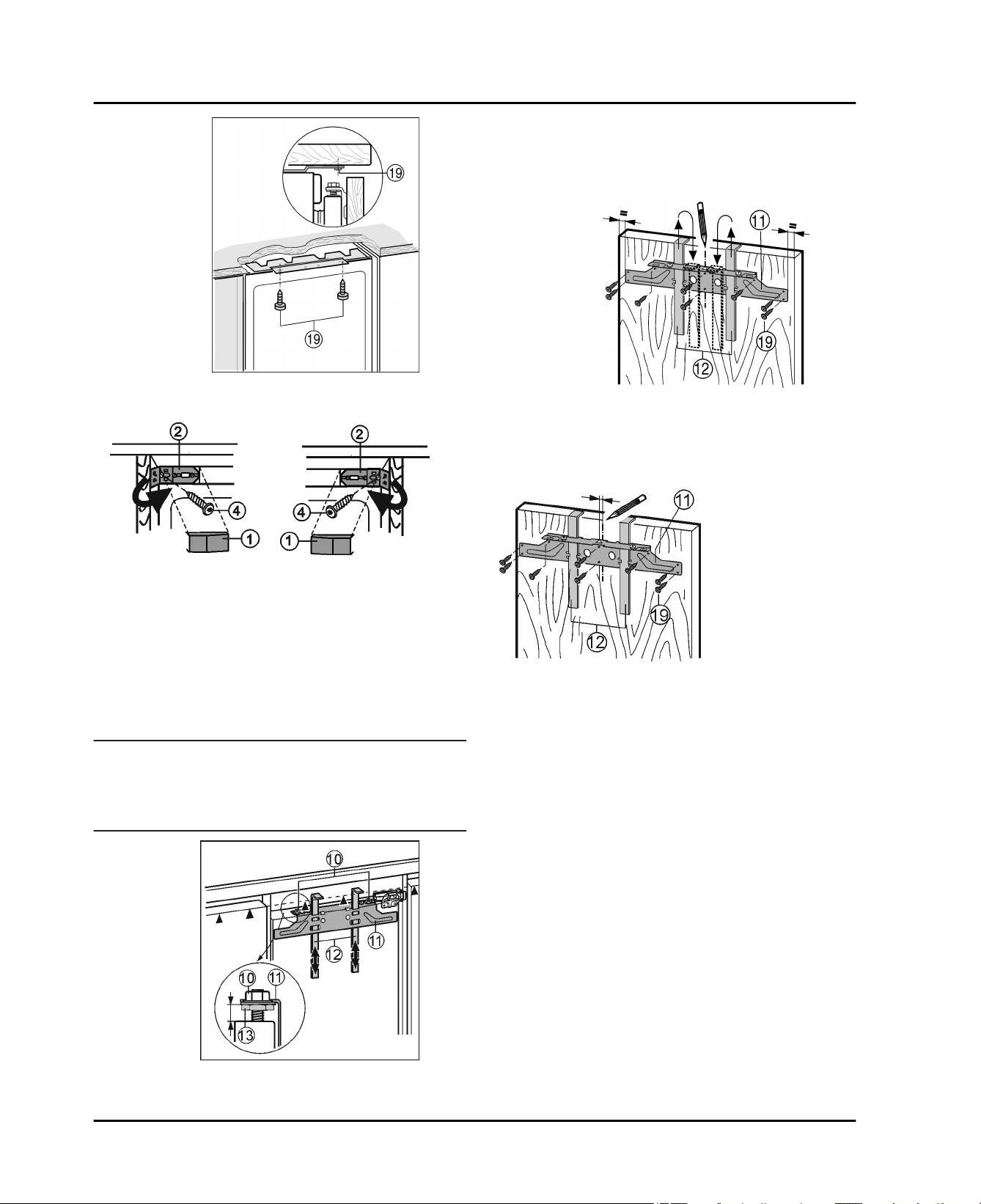
Start-up
Screw in long chipboard screws
u
Side fastening:
Fig. 15 (19)
Fig. 15
at the top.
Raise the fitting aids
u
Fig. 17 (12)
to unit door height.
Bottom stop edge of ▲the fitting aid = top edge of the
unit door to be fitted.
Unscrew the crosspiece
u
locknuts
Hang the crosspiece
u
Fig. 17 (10)
door using the fitting aids
Fig. 17 (11)
.
Fig. 18 (11)
Fig. 18 (12)
by undoing the
on the inside of the unit
.
With a 23-5/8 '' (600 mm) wide recess:
Align the crosspiece
u
Fig. 18 (11)
to the middle of the
door.
Fig. 18
Fig. 16
Fasten the appliance on the right and left with screws
u
Fig. 16 (4)
Fig. 11 (3)
Fold up the side part of the mounting bracket
u
on the side wall of the unit. Tighten the screw
fully.
Fig. 16 (2)
2 and lock it in place.
Snap the cover
u
Fig. 16 (1)
back into place.
4.3.2 Installing the unit door
Installing the handle on the unit door
u
Note
To guarantee that the pull-out compartment will pull-out
evenly:
Always install the unit handle in the middle of the unit
u
door.
Fig. 19
With a 24-1/32 '' (610 mm) wide recess:
Align the crosspiece
u
Fig. 19 (11)
door.
Left strip: Move the crosspiece
u
Fig. 19 (11)
the left.
-or-
Right strip: Move the crosspiece
u
to the right.
For chipboard doors
Secure the crosspiece
u
Fig. 18 (19)
.
Fig. 18 (11)
For frame and panel doors
Secure the crosspiece
u
Fig. 18 (19)
Lift up fitting aids
u
at the edge.
Fig. 18 (12)
Fig. 18 (11)
, turn round and insert into
the adjacent openings.
to the middle of the
1/4 (6 mm) to
Fig. 19 (11)
1/4 (6 mm)
with at least 6 screws
with 4 screws
Fig. 17
Check the 5/16 '' (8 mm) presetting. (Distance between
u
appliance door and lower edge of crosspiece)
* Depending on model and options 9
Start-up
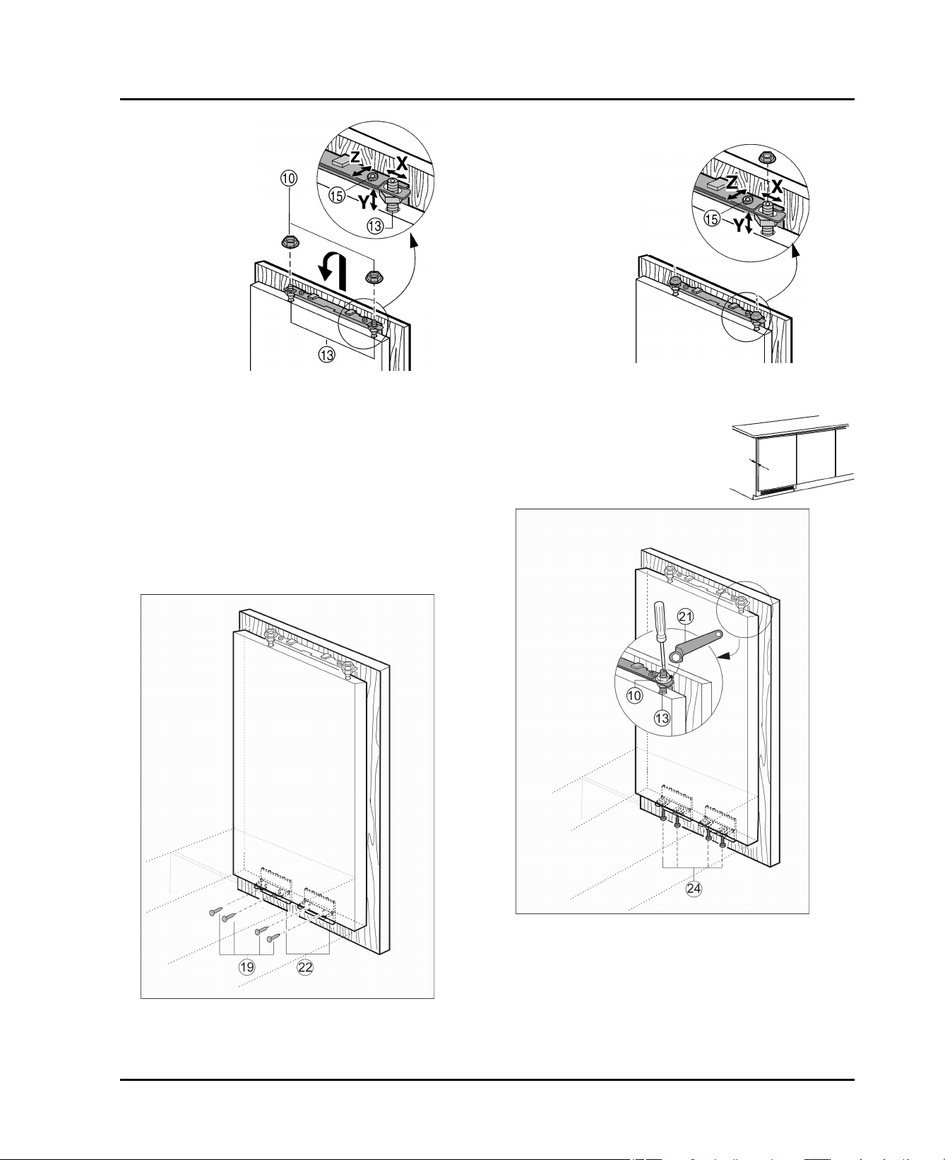
Screw the appliance door to the unit door with screws
u
Fig. 21 (19)
through the mounting brackets
Fig. 21 (22)
.
Attach the unit door on the adjusting bolts
u
and loosely screw locknuts
Fig. 20 (10)
Fig. 20 (13)
onto the
adjusting bolts.
Close the door.
u
Check the gap between the door and the surrounding
u
unit doors
To laterally align the unit door Move the unit door in the
u
X direction.
To align the unit door in the Y direction (height) and in
u
lateral inclination: Adjust the adjusting bolts
Fig. 20 (13)
with a screwdriver.
The unit door is flush and in alignment with the
w
surrounding unit fronts
Tighten the locknuts
u
Fig. 20 (10)
.
Fig. 20
Align the unit door in depth Z : loosen the upper screws
u
Fig. 22 (15)
, lower screws
Fig. 23 (24)
, then move the
door.
Do not allow the knobs and
u
sealing lips to contact the door important for function
Set an air gap of 3/32 '' (2 mm)
u
between the unit door and the
body of the unit.
Fig. 22
Fig. 23
Check the fit of the door and re-adjust, if necessary
u
Tighten all screws
u
Screwing the unit door to the appliance door.
u
Drill pilot holes in the door of the unit (you could make a
u
Fig. 21
Tighten the locknuts
u
Fig. 23 (21)
Fig. 23 (13)
, while counter-holding the adjusting bolts
with a screwdriver.
Fig. 23 (10)
with the ring wrench
preliminary hole with a bradawl)
10 * Depending on model and options
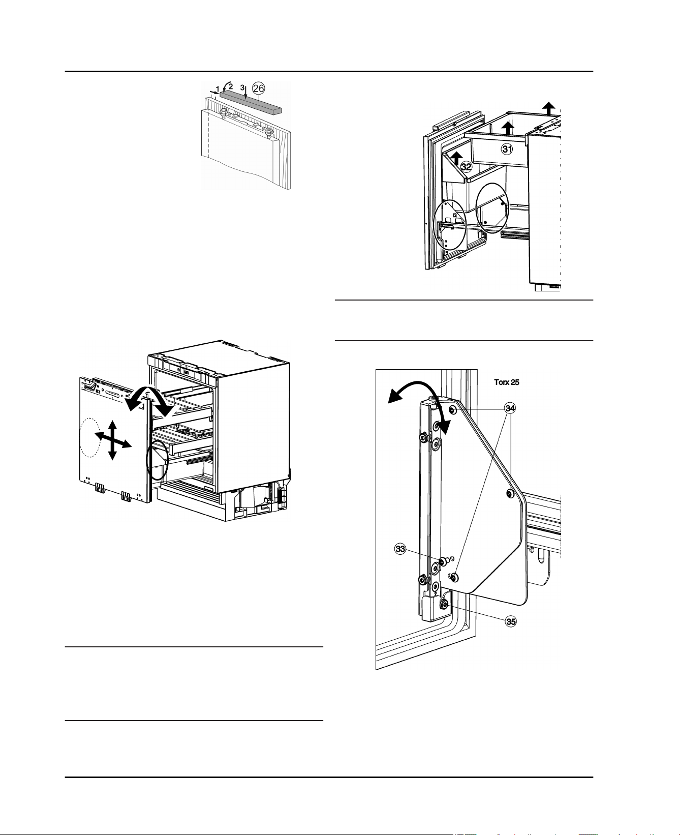
Position the upper cover
u
Fig. 24 (26)
place.
Check the following points to make sure the appliance is
installed correctly Otherwise, icing up, the formation of
condensate, and malfunctions can occur
The door must close properly
w
The unit door must not touch the body of the unit
w
and snap into
Fig. 24
4.4 Adjust the fit of the door seal
It may be necessary to adjust the appliance door
depending on the weight of the unit door.
After assembling the unit door, check that the door seal is
fully fit up against the appliance body.
Start-up
4.4.1 Adjusting the inclination of the door
Fig. 26
Note
Always perform the adjustment on both the right and
u
left side!
Fig. 25
The adjustment settings are located to the right and left
below the bottle shelf on the inner door.
The appliance is delivered with the adjustment setting in
the 0 position.
The following settings are possible:
Inclination ± 1°
q
Upward adjustment of 4 mm
q
Downward adjustment of 2 mm
q
2 mm adjustment to the left or right
q
Lift up the vegetable drawer
u
Fig. 26 (32)
.
Fig. 26 (31)
and bottle shelf
NOTICE
Functional impairments and risk of damage!
Only use the appliance door adjustment to ensure that
u
the door seal of the pull-out compartment lies 100% up
against the appliance body and not to adjust the unit
door.
If necessary, place a luminous flashlight inside to check
the tight closure of the door.
* Depending on model and options 11
Fully unscrew the screws
u
Dispose of the screws
w
be needed.
Only loosen the screws
u
Fig. 27 (33)
Fig. 27 (33)
Fig. 27 (34)
.
as they will no longer
with 1 to 2 turns.
Fig. 27
Start-up
Turn the adjusting screw
u
direction: the top of the door tilts away from the appliance body. In an anticlockwise direction: the top of the
door tilts towards the appliance and the bottom tilts
away from the appliance body.
After adjusting the inclination, retighten all screws
u
Fig. 27 (34)
.
Fig. 27 (35)
. In a clockwise
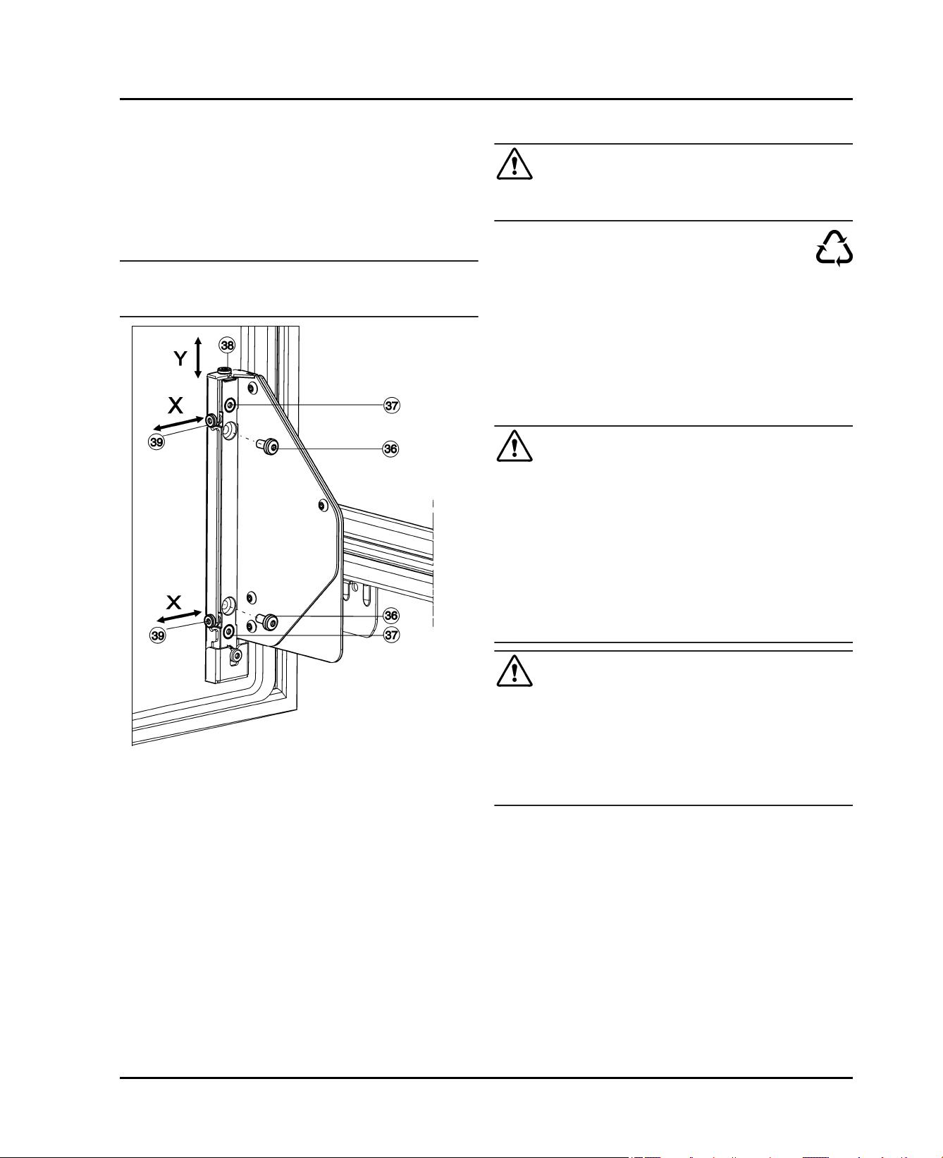
4.4.2 Leveling the door
Note
Always perform the adjustment on both the right and
u
left side!
4.5 Disposal of packaging
WARNING
Danger of suffocation from packaging materials and films!
Do not allow children to play with packaging materials.
u
The packaging is made from recyclable materials:
Corrugated card/cardboard
Parts made of foamed polystyrene
Films and bags from polyethylene
Packing bands from polypropylene
Wood frame nailed together with a polyethylene
window*
Take the packaging material to an official collection
u
point.
4.6 Connecting the appliance
WARNING
Electrical shock hazard!
Start-up should only take place once the appliance has
u
been installed according to these instructions.
Electrically ground appliance.
u
Do not ground to a gas pipe.
u
Check with a qualified electrician if you are not sure the
u
appliance is properly grounded.
Do not have a fuse in the neutral or grounding circuit.
u
Do not use an extension cord, power bar or a multiple
u
socket adapter.
Do not use a power cord that is frayed or damaged.
u
WARNING
Electrical shock hazard!
This appliance is equipped with a three-prong (grounding)
Fig. 28
Height adjustment, Y:
Fully screw out the screws
u
Dispose of the screws
w
be needed.
Only loosen the screws
u
Turn the adjusting screw (38). In a clockwise direction:
u
the door moves max. 4 mm upwards. In an anticlockwise direction: the door moves max. 2 mm downwards.
Retighten all screws
u
Lateral adjustment, X:
If the screws
u
fully.
Only loosen the screws
u
Adjust the adjusting screws
u
desired lateral adjustment direction.
Retighten the screws
u
ment is complete.
Reinsert the bottle shelf
u
drawer
12 * Depending on model and options
Fig. 28 (36)
Fig. 26 (31)
.
Fig. 28 (36)
Fig. 28 (36)
Fig. 28 (37)
Fig. 28 (37)
are still present, unscrew them
Fig. 28 (37)
Fig. 28 (39)
Fig. 28 (37)
Fig. 26 (32)
.
as they will no longer
with 1 to 2 turns.
.
with 1 to 2 turns.
according to the
after the lateral adjust-
and the vegetable
polarized plug for your protection against possible shock
hazards. Electrical Grounding Required.
Do not remove the round grounding prong from the
u
plug.
Use only an grounded adapter.
u
Wait 1 hour after installation before you plug in the
appliance. This allows the refrigerant and system lubrication to reach equilibrium.
Make sure that the voltage of the power network
matches the connection voltage of the appliance. A
power supply of 110 - 120 Volt, 60 Hz and 15 Ampere is
required for device operation and must be protected by
a main switch or a fuse.
We recommend using a dedicated circuit for this appli-
ance to prevent electrical overload.
Follow all Federal, State and local electrical, fire and
building codes and ordinances when installing the
receptacle and / or the appliance.
In some communities, a wall switch is required to turn
power to the appliance ON and OFF.
Operation
To reduce the risk of fire, electric shock, or personal
injury, installation work and electrical wiring must be
done by a qualified electrician in accordance with all
applicable codes and standards, including fire-rated
construction.
The Power Plug must be easily accessible so that the
appliance can be disconnected from the mains quickly
in an emergency. It must not be behind the back of the
appliance.
4.7 Switching the appliance on
Open the door.
u
Press the On/Off button
u
The appliance is switched on The temperature display
w
displays the temperature setting.
Once all indicator LEDs on the temperature display
w
light up, demonstration mode is enabled. Contact
Customer Services.
Fig. 2 (1)
.
5 Operation
5.1 Refrigerating food
Note
Load the pull out drawer with the bottle rack and vege-
u
table drawer with no more than
20 Umrechnung von kg wurde noch nicht definiert!
(20 kg )of food.
WARNING
Danger of fire
Do not use electrical appliances inside the food storage
u
compartments of the appliance, unless they are of the
type recommended by the manufacturer.
the room temperature of the installation location
the type, temperature and amount of food.
-
Recommended temperature setting: 41 °F (5 °C)
Call up the temperature function: Press the Set button
u
Fig. 2 (2)
On the temperature display, the LED flashes the current
w
temperature.
Press the Set button
u
show the desired temperature.
Note
By pressing and holding down the Set button, a slightly
u
colder value can be set within a small temperature
range (e.g. between 41 °F (5 °C) and 45 °F (7 °C)). On
the temperature display, the illuminated LEDs then
show the next lower temperature range.
once.
Fig. 2 (2)
until the illuminated LEDs
5.3 SuperCool
With SuperCool you switch to the highest cooling
performance to reach lower cooling temperatures. Use SuperCool to rapidly cool large quantities of food.
If SuperCool has been switched on the appliance runs at
maximum refrigerating capacity. As a result the noises
from the refrigeration unit may temporarily be louder.
SuperCool will use more energy than normal operation.
5.3.1 Cooling with SuperCool
Briefly press the SuperCool button
u
The SuperCool button
w
The cooling temperature drops to the coldest value.
w
SuperCool is switched on.
SuperCool automatically switches itself off after about
w
6-12 hours. The appliance returns to work in the
energy-saving normal mode.
Fig. 2 (4)
Fig. 2 (4)
lights up.
.
Store perishable food such as ready-meals, meat and
u
sausage products and in the middle of the coldest
zone. Store butter and preserves in the top part. (see
The appliance at a glance)
Use recyclable plastic, metal, aluminum and glass
u
containers and cling film to wrap foods.
Always use closed containers for liquids and for food
u
that may give off or be tainted by odor or flavor transfer
or cover them.
Foods which give off a large amount of ethylene gas
u
and those that are sensitive to this gas, such as fruit,
vegetables and salad, should always be separated or
wrapped so as not to reduce the storage life; for
example, do not store tomatoes together with kiwi fruits
or cabbage.
Do not store food too close together to enable sufficient
u
air circulation.
5.3.2 To prematurely switch off SuperCool
Briefly press the SuperCool button
u
The SuperCool button
w
SuperCool is switched off.
w
Fig. 2 (4)
Fig. 2 (4)
goes out.
.
5.4 Moving the supporting bars
CAUTION
Danger of lacerations!
The storage shelf can shatter if dropped or mishandled.
You could cut yourself on the pieces of broken glass.
Only remove storage shelves when there is nothing on
u
them.
5.2 Setting the temperature
The temperature depends on the following factors:
the number of times the door is opened
-
* Depending on model and options 13
Maintenance
6 Maintenance
6.1 Thawing
6.1.1 Defrosting the refrigerator
Grasp the right and left supporting bars and carefully
u
remove them from above and then insert them in the
new position until the mounts engage.
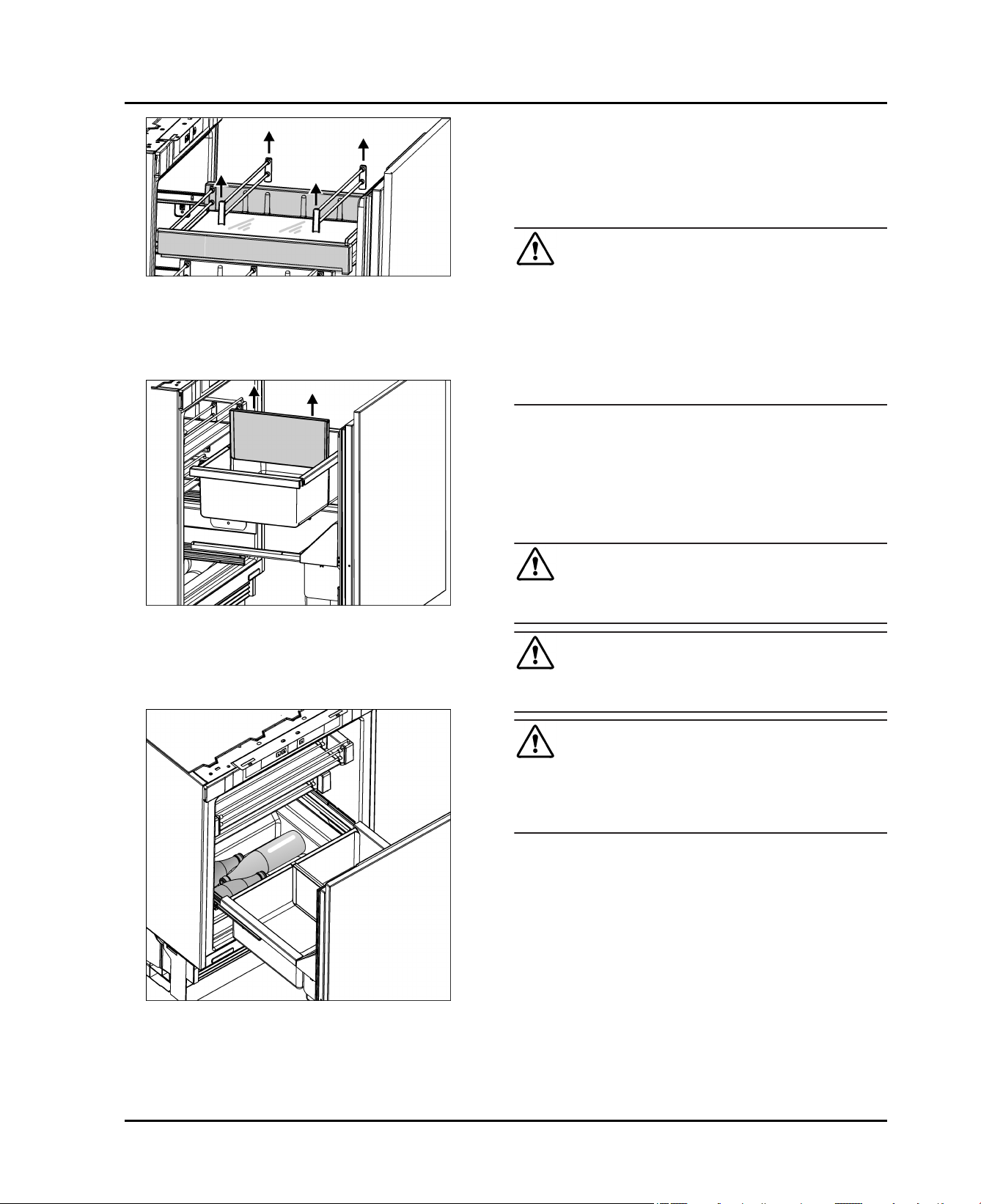
5.5 Dividing the vegetable drawer
The partition can be used to divide the vegetable
u
drawer. Insert the partition on the guide racks or simply
pull them out from the top.
5.6 Storing in the floor recess
Fig. 29
Fig. 30
WARNING
Risk of injury and damage
Do not use mechanical devices or other means to
u
accelerate the defrosting process, other than those
recommended by the manufacturer.
Do not use any electrical heating or steam cleaning
u
equipment, naked flames or defrosting sprays for
defrosting.
Do not remove ice with sharp objects.
u
The fridge compartment defrosts automatically. The
defrosted water will evaporate. Drops of water on the back
wall are a functional feature; this is completely normal.
Clean the drain opening regularly so that the condensa-
u
tion water can drain away. (see 6.2)
6.2 Cleaning the appliance
WARNING
Danger of electric shock.
Unplug refrigerator or disconnect power.
u
WARNING
Danger of fire
Do not damage the refrigerant circuit.
u
WARNING
Risk of injury or damage due to hot steam.
Hot steam can cause scalding/burns and damage to
surfaces.
Do not use steam cleaners.
u
Fig. 31
Unopened and securely closed bottles and packages
u
can be stored in the storage space in the floor recess.
14 * Depending on model and options
Maintenance
NOTICE
Incorrect cleaning damages the appliance.
Do not use concentrated cleaning agents.
u
Do not use steel wool or sponges that scour or scratch.
u
Do not use caustic or abrasive cleaning materials or
u
those containing sand, chloride, or acids.
Do not use chemical solvents.
u
Do not damage or remove the rating plate on the inside
u
of the appliance. It is vital for the customer service
department.
Do not pull off, kink or damage any cables or other
u
components.
Do not let cleaning water get into the drain gutter, the
u
ventilation grille and electrical parts.
Use soft cleaning cloths and a multi-purpose cleaning
u
agent with a neutral pH value.
Only use food-compatible cleaning and care agents
u
inside the appliance.
Empty the appliance.
u
Disconnect the power plug.
u
Clean the ventilation grilles regularly.
u
Dust deposits increase energy consumption.
w
Clean the plastic surfaces, outside and inside, by
u
hand using lukewarm water and a little dish washing
liquid.
To clean the drain
u
opening: Remove
deposits with a thin instrument, e.g. a cotton bud.
Note
If the storage compartment can no longer be pulled out
u
as far as it could initially, pull the telescopic rails out
fully once. The ball bearing cage on the telescopic rails
will then re-align and it will be possible to pull the
compartment out fully again.
Clean the telescopic rails with a damp cloth only. The
u
grease in the tracks is for lubrication purposes and
should not be removed.
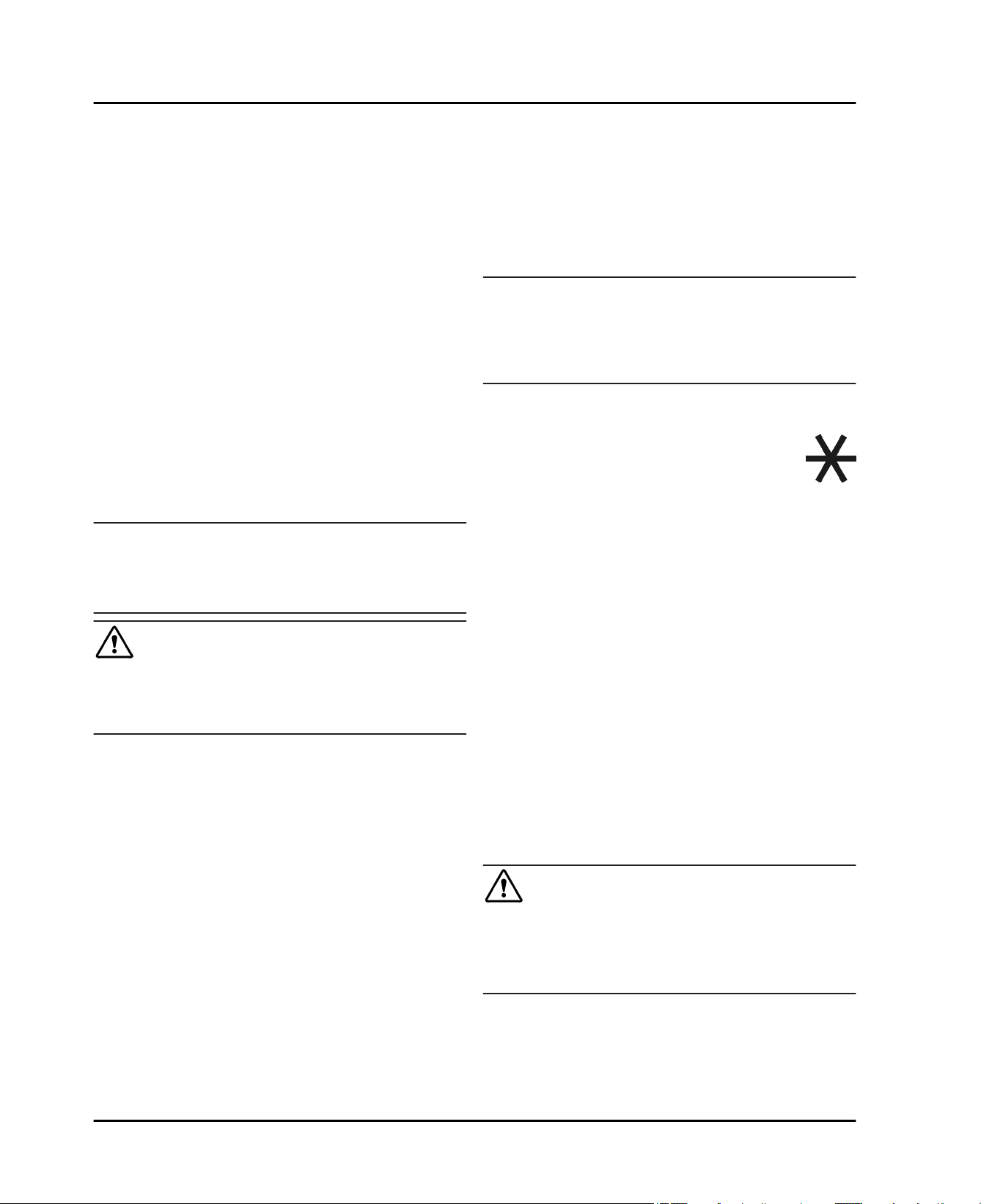
To dismantle the rack: Lift the supporting bars
u
Fig. 32 (1)
the bars
glass floor.
upwards, remove the retainers
Fig. 32 (3)
and the side parts
Fig. 32 (2)
Fig. 32 (4)
from the
from
Clean fittings by hand using lukewarm water and a
u
little dish washing liquid.
To remove the rack: lift up at the back as in the picture
u
and pull out forwards.
Fig. 32
Fig. 33
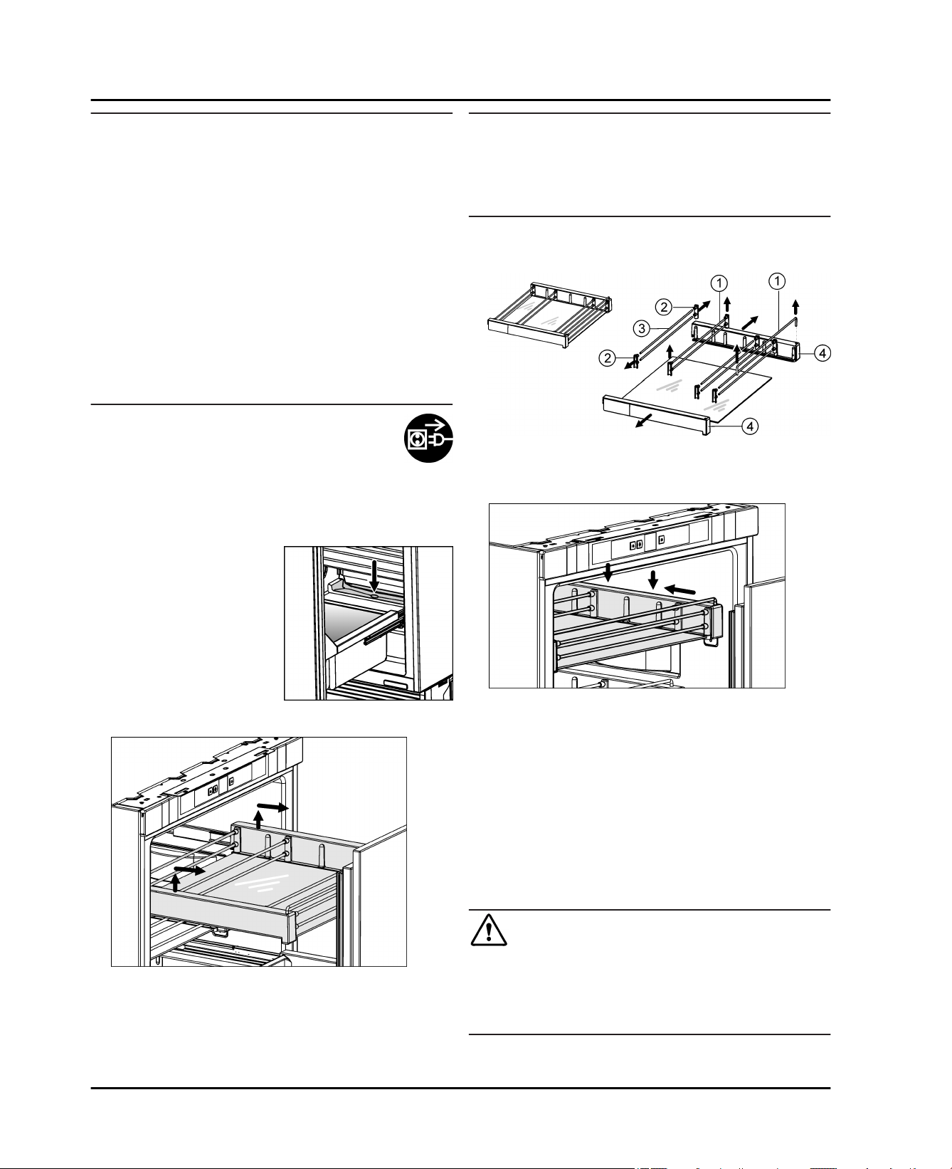
To insert the rack: Push the telescopic rails in.
u
Put the storage compartment on the telescopic rails
u
and push backwards until it clicks into place.
After cleaning:
Wipe the appliance and accessories dry.
u
Connect the appliance and switch it on again.
u
Put the food back in the appliance.
u
6.3 Customer service
First check whether you can remedy the fault yourself
(see Troubleshooting). If this is not the case, please
contact a qualified service provider.
WARNING
Risk of injury from repairs by non-professionals.
Repairs and work on the appliance and the power
u
supply cable not described in the Manual (see Maintenance) should only be carried out by a qualified service
provider.
* Depending on model and options 15
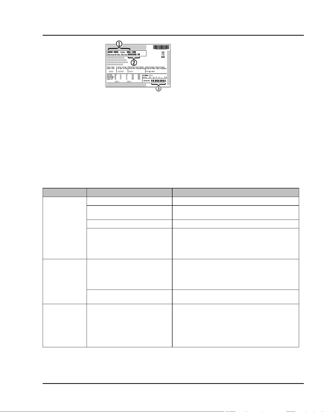
Troubleshooting.
Read the appliance
u
designation
Fig. 34 (1)
Fig. 34 (2)
no.
the rating plate. The
rating plate is located
inside the appliance
on the left-hand side.
Notify a qualified service provider, specifying the fault,
u
appliance designation
and serial
This will help us to provide you with a faster and more
w
accurate service.
Keep the appliance closed until the Customer Service
u
engineer arrives.
The food will stay cool longer.
w
Disconnect the power plug (do not pull on the power
u
cord to do this) or switch off the fuse.
6.4 Appliance Information
Make a note of this information when the appliance is
installed:
, service no.
and serial
Fig. 34 (3)
Fig. 34 (3)
from
no.
Fig. 34 (1)
, service no.
Fig. 34
Fig. 34 (2)
Type Designation: _____________________
Service Number: _____________________
Appliance / Serial Number: _____________________
Date of purchase: _____________________
Where purchased: _____________________
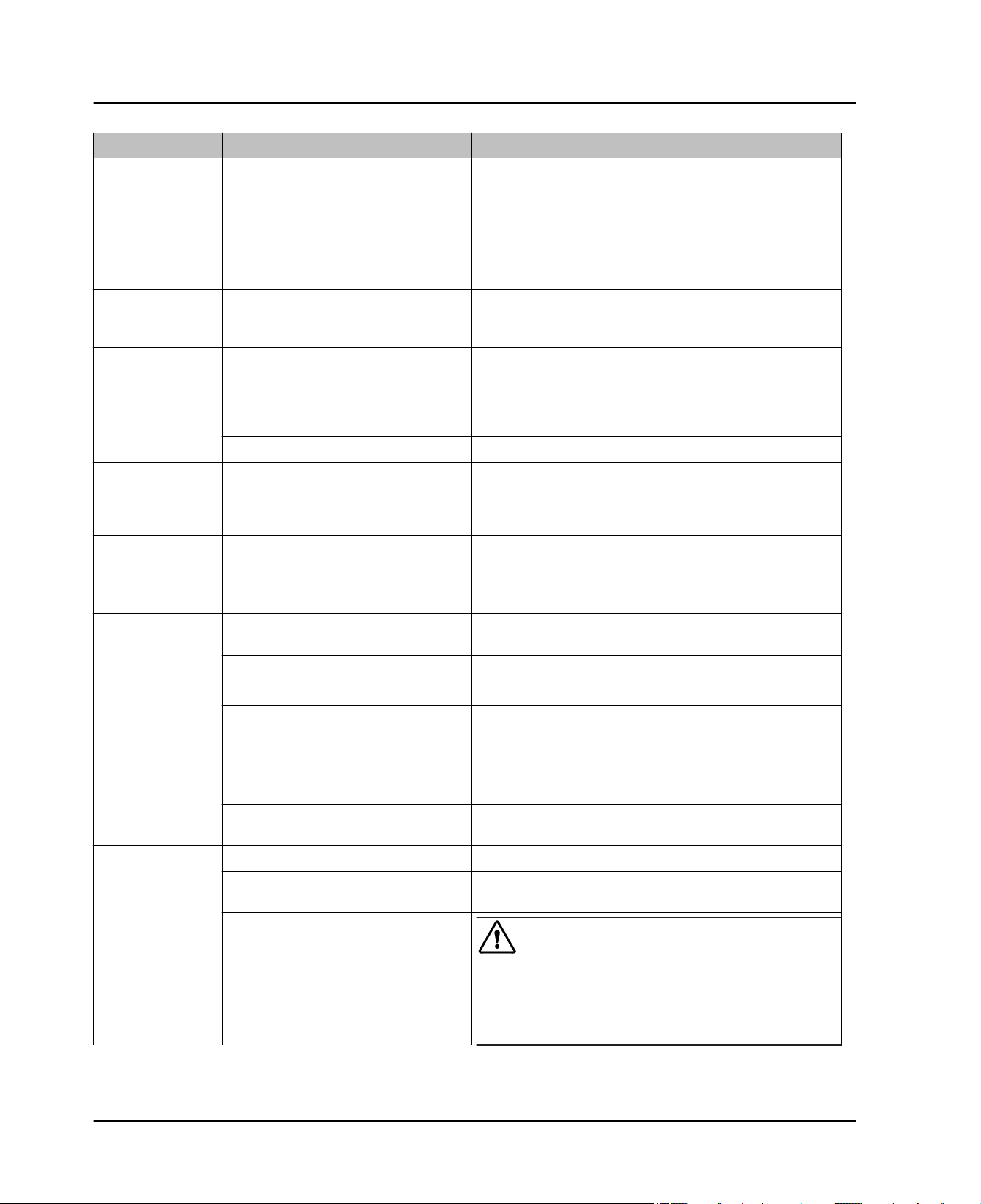
7 Troubleshooting.
Your appliance is designed and manufactured for reliable
operation and a long lifespan. If a malfunction nonetheless occurs during operation, please determine if the
malfunction is due to an operating error. If a service call
determines operator error, you will be charged for the
costs incurred, even during the warranty period. You may
be able to rectify the following problems yourself:
Problem Possible Cause Correction
The appliance
does not work.
The compressor
runs for a long
time.
A LED at the
lower rear of the
appliance (for
the compressor)
flashes regularly
every 15
seconds*.
The appliance is not switched on.
The power plug is not properly
inserted in the wall socket.
The fuse in the wall socket is not OK.
Power failure
When less refrigeration is required,
the speed-controlled compressor
switches to a low speed. Although
the running time is increased as a
result, energy is saved.
SuperCool function is activated.
The inverter is equipped wth a diagnostic LED.
Switch on the appliance.
u
Check the power plug.
u
Check the fuse.
u
Keep the appliance closed.
u
Protect the food: place dry ice on top of the food or
u
use an alternate freezer, if the power failure persists
for some time.
Do not re-freeze defrosted food.
u
This is normal in energy-saving models.
u
The compressor runs long to rapidly cool food. This
u
is normal.
The flashing is normal.
u
16 * Depending on model and options
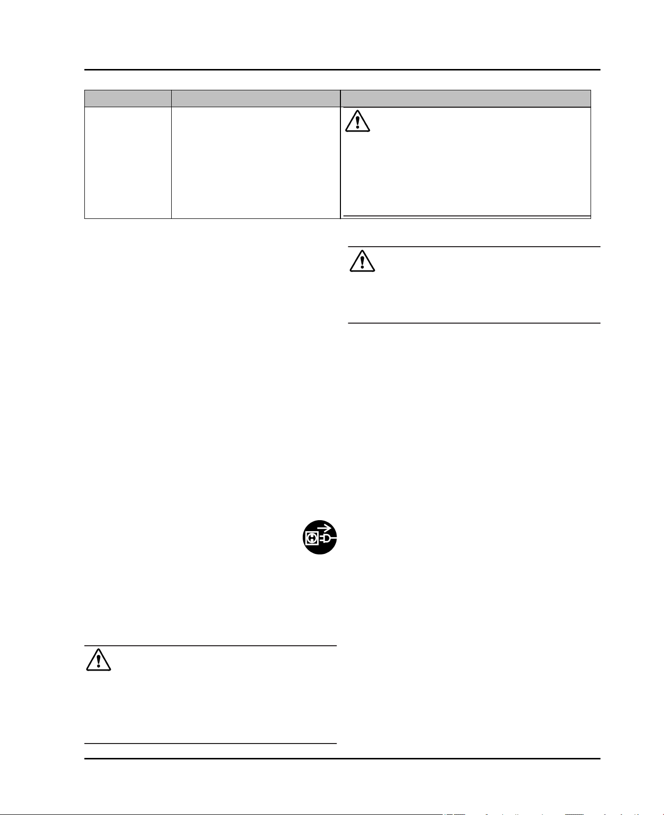
Problem Possible Cause Correction
Troubleshooting.
Noises are too
loud.
A gurgling
sound
A faint clicking
sound
A hum. It is
briefly a little
louder when the
refrigeration unit
(the motor)
switches on.
Vibration noise
The outside
surfaces of the
appliance are
hot*.
The different speed levels of speedcontrolled* compressors can cause
them to generate various noises
during operation.
This sound comes from the refrigerant flowing in the refrigeration
circuit.
The sound always occurs when the
refrigeration unit (the motor) automatically switches on or off.
The refrigeration increases automatically when the SuperCool function is
activated, fresh food has just been
placed in the appliance or the door
has been left open for a while.
The ambient temperature is too high.
The appliance is not standing firmly
on the floor As a result, adjoining
units or objects are set into vibration
by the running refrigeration unit
The heat of the refrigerant circuit is
used to prevent condensate from
forming.
These noises are normal.
u
The sound is normal.
u
The sound is normal.
u
The sound is normal.
u
Solution: (see 1.3)
u
Check the installation and, if necessary, re-align the
u
appliance.
Move bottles and containers apart.
u
This is normal.
u
The temperature
is not cold
enough.
The interior light
does not turn
on.
The door of the appliance is not
closed properly.
Insufficient ventilation.
The ambient temperature is too high.
The appliance was opened too
frequently or for too long.
The appliance is too near to a heat
source (stove, heater etc).
The appliance was not properly
installed in the recess.
The appliance is not switched on.
The door was open for longer than 15
minutes.
The LED interior light is faulty or the
cover is damaged
Close the appliance door.
u
Clear and clean the ventilation grille.
u
Solution: (see 1.3)
u
Wait to see whether the required temperature resets
u
itself by itself. If not, contact the customer service
department (see Maintenance).
Change location of appliance or the heat source.
u
Make sure the appliance was installed correctly and
u
the door closes properly.
Switch on the appliance.
u
The interior light automatically switches itself off if
u
the door has been open for about 15 minutes.
WARNING
Risk of injury from electrical shock.
Live parts are under the cover.
The LED interior light should only be replaced or
u
repaired by the Customer Service department or by
engineers trained to do so.
* Depending on model and options 17
Putting appliance out of service
Problem Possible Cause Correction
WARNING
Risk of injury from LED lamp!
The lighting intensity of the LED light complies with laser
class 1/1M.
If the cover is faulty:
Do not gaze directly at this lighting unit with optical
u
lenses while very close to the light source. This can
cause damage to your eyes.
8 Putting appliance out of service
8.1 Vacation Tips
Short vacations: If you will be away for less than four
weeks
Use all perishables.
u
Long vacations: If you will be away for a month or more
Remove all food from the appliance.
u
Turn OFF the appliance.
u
Clean the appliance (see 6.2) .
u
Leave the door open to prevent unpleasant odors.
u
This will also keep mold from building up.
w
Danger of electric shock.
u
u
Ensure during and after disposal that the appliance isn't
stored in the vicinity of gasoline or other flammable vapors
and liquids.
When disposing of the appliance, ensure that the refrigeration circuit is not damaged to prevent uncontrolled
escape of the refrigerant it contains (data on type plate)
and oil.
WARNING
Cut off the plug from the power cord and discard.
Cut off the power cord from the discarded appliance.
Dispose of separately from the appliance.
8.2 Switching the device off
Press and hold the On/Off button
u
display becomes dark. Release button.
Fig. 2 (1)
until the
8.3 Decommissioning
Empty the appliance.
u
Pull out the power plug.
u
Clean the appliance (see 6.2) .
u
Leave the door open to prevent bad smells.
u
9 Disposing of the appliance
Follow the local regulations for the disposal of appliances.
Old appliances can be dangerous. Contact the local
refuse collection department for additional information.
DANGER
There is a risk of suffocation.
Children playing can shut themselves in and suffocate.
Take the door(s) off.
u
Remove the drawers.
u
Leave the storage shelves in the appliance so that chil-
u
dren cannot easily climb into the appliance.
10 Liebherr Warranty Plan
FULL TWO YEAR WARRANTY - For two years from the
date of original purchase, your Liebherr warranty covers
all parts and labor to repair or replace any part of the
product which proves to be defective in materials or workmanship.
FULL FIVE YEAR WARRANTY - For five years from the
date of original purchase, your Liebherr warranty covers
all parts and labor to repair or replace any components
that prove to be defective in materials or workmanship in
the sealed system. The “Sealed System” means only the
compressor, condenser, evaporator, drier and all
connecting tubing.
LIMITED 6TH THROUGH 12TH YEAR WARRANTY -
From the 6th through 12th year from the date of original
purchase, your Liebherr warranty covers all parts that
prove to be defective in materials or workmanship in the
Sealed System (parts only).
TERMS APPLICABLE TO EACH WARRANTY
All service provided by Liebherr under the warranty must
be performed by authorized Liebherr service representatives, unless otherwise specified by Liebherr. Service will
be provided in the home during normal business hours.
This warranty applies only to products installed for normal
residential use. Details regarding a non-residential
warranty are available on request.
18 * Depending on model and options
 Loading...