

Page 1
Installation instructions
Refrigerators and freezers for integrated use, door-on-door
090118
S/UIK/P 15../ S/UIG/N 15../ S/UIB 15 ...
7086644 - 00
Page 2
General safety information
Contents
1 General safety information................................... 2
2 Putting into operation............................................ 2
2.1 Transporting the appliance....................................... 2
2.2 Installing the appliance............................................. 2
2.2 Appliance dimensions.............................................. 3
2.3 Recess dimensions.................................................. 3
2.4 Unit door................................................................... 3
2.5 Changing the door direction..................................... 4
2.6 Installing the appliance in the recess........................ 6
2.7 Installation................................................................ 6
2.8 Disposing of packaging............................................ 10
2.9 Connecting the appliance......................................... 10
The manufacturer works constantly on the further development
of all the types and models. Therefore please understand that
we have to reserve the right to make design, equipment and
technical modifications.
To get to know all the benefits of your new appliance, please
read the information contained in these instructions carefully.
The instructions apply to several models. Differences may
occur. Text relating only to specific appliances is marked with
an asterisk (*).
Instructions for action are marked with a , the results of
action are marked with a .
2 Putting into operation
2.1 Transporting the appliance
Risk of injury and danger of damage as a result of incorrect
transport!
u
u
u
2.2 Installing the appliance
Risk of fire due to short circuit!
If the mains cable/connector of the appliance or of another
appliance touch the rear of the appliance, the mains cable/
connector may be damaged by the appliance vibrations,
leading to a short circuit.
u
u
CAUTION
Transport the appliance in a packed condition.
Transport the appliance upright.
Do not transport the appliance without assistance.
WARNING
Stand the appliance so that it is not touched by connectors
or main cables.
Do not plug the appliance or any others into sockets located
near the rear of the appliance.
1 General safety information
-
Only install, connect and dispose of the appliance according to the instructions. Take
particular note of “Recess dimensions” and
“Ventilation of the kitchen unit”.
-
The socket must be easily accessible so that
the appliance can be quickly disconnected
from the supply in an emergency. It must be
outside the area of the rear of the appliance.
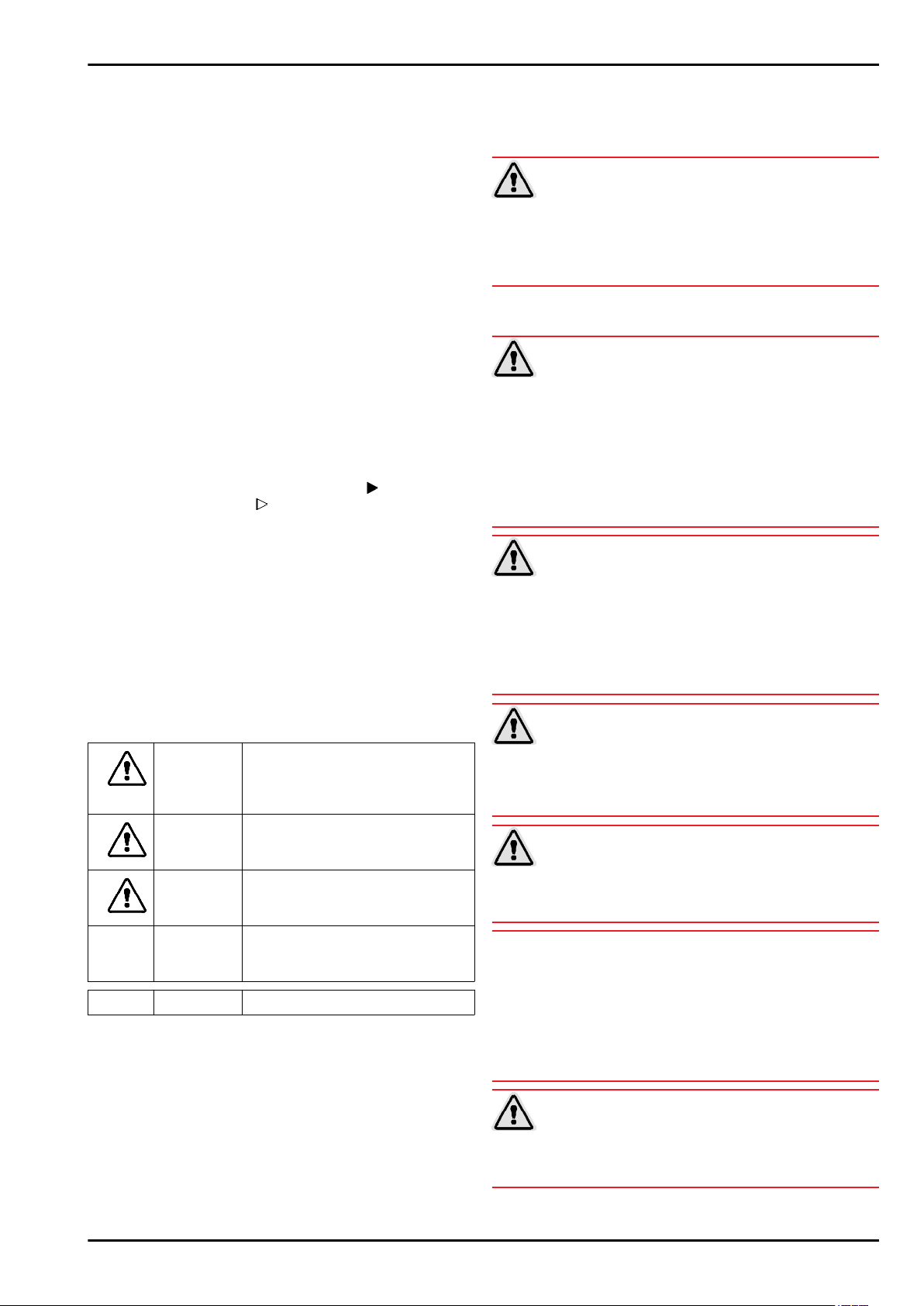
DANGER identifies a situation involving direct
danger which, if not obviated, may
result in death or severe bodily
injury.
WARNING identifies a dangerous situation
which, if not obviated, may result in
death or severe bodily injury.
CAUTION identifies a dangerous situation
which, if not obviated, may result in
minor or medium bodily injury.
NOTICE identifies a dangerous situation
which, if not obviated, may result in
damage to property.
Note identifies useful information and tips.
Fire hazard due to dampness!
If live parts or the mains lead become damp this may cause
short circuits.
The appliance is designed for use in enclosed areas. Do not
u
operate the appliance outdoors or in areas where it is
exposed to splash water or damp conditions.
Only use the appliance when it is installed.
u
WARNING
WARNING
Fire hazard due to refrigerant!
The refrigerant R 600a is environmentally friendly but flammable. Escaping refrigerant may ignite.
Do not damage the piping of the refrigeration circuit.
u
WARNING
Fire hazard and danger of damage!
Do not place appliances emitting heat e.g. microwaves,
u
toasters etc. on the appliance!
NOTICE
Risk of damage due to condensation!
When assembling an appliance name beginning with S... or
a side-by-side (SBS) appliance:
The appliance can be installed next to another refrigerator or
u
freezer.
If your appliance name does not begin with S...:
Do not install the appliance next to another refrigerator or
u
freezer.
Blocked ventilation openings pose a risk of fire and damage!
WARNING
Always keep the ventilation openings clear. Always ensure
u
that the appliance is properly ventilated!
2 * Depending on model and options
Page 3
Risk of tipping
WARNING
The appliance must be fixed in accordance with the instruc-
u
tions in order to prevent a hazard caused by the instability of
the appliance.
In the event that the appliance is damaged, contact the
q
supplier immediately before connecting to the mains.
The floor at the site must be flat and level.
q
Do not install the appliance in a location where it is exposed
q
to direct radiation of the sun, next to a cooker, heater and
similar.
Do not install the appliance alone: it is best to work together
q
with two or more people.
The more R 600a refrigerant there is in the appliance, the
q
larger the room in which the appliance is standing needs to
be. In rooms that are too small, a flammable mix of gas and
air may be created if there is a leak. According to the EN 378
standard, every 11 g of R 600a refrigerant requires at least
1 m3 space in the room for the appliance. The amount of
refrigerant in your appliance is on the type plate inside the
appliance.
If the appliance is installed in a very damp environment,
q
condensed water may form on the outside of the appliance.
Always make sure that there is good ventilation - both at air
inlet and outlet - at the site of installation.
After installation:
Remove protective films, adhesive tapes and transport lock
u
parts etc.
Putting into operation
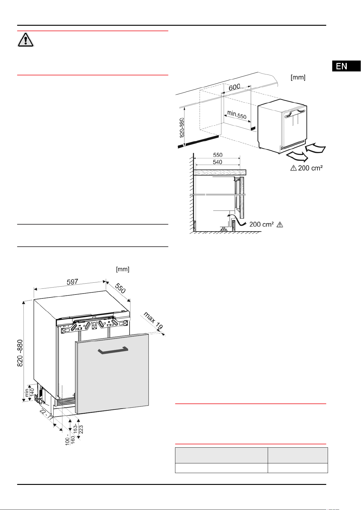
2.3 Recess dimensions
This is a base unit and should be installed under a worktop.
The kitchen units must be fitted according to the specifications,
allowing sufficient ventilation to ensure the equipment works
properly.
Note
Clean the appliance (see Operating Instructions,
u
Chapter "Cleaning the appliance").
2.2 Appliance dimensions
Fig. 2
The specified energy consumption applies to a unit depth of
560 mm. The appliance will work properly at a unit depth of 550
mm, but at a slightly higher energy consumption.
Check the wall thickness of the adjoining cabinets: it must
u
be min. 16 mm thick.
Align the kitchen unit using a spirit level and marking square
u
and if necessary compensate with shims.
Ensure that the floor and walls of the unit are at right angles
u
to one another.
2.4 Unit door
One door is required for the kitchen unit.
-
The door must be minimum 16 mm and maximum 19 mm
-
thick.
There must be a gap of minimum 3 mm width between the
-
door and the unit door located above it (if one exists).
The width of the unit door depends on the style of the
-
kitchen and the gap size between the door panels of the
cabinet. Generally, there should remain a vertical gap of
3 mm between the unit doors.
If there are more cupboards the upper edge of the cabinet
-
door should be at the same height as the doors on the next
cabinet.
The unit door must be planar and mounted stress-free.
-
NOTICE
Risk of damage from over-heavy unit door!
If the unit door is too heavy, damage to the hinges and resulting
impairment of function cannot be excluded.
Before mounting the unit door, make sure that the door does
u
not exceed the approved unit door weight.
Fig. 1
Appliance model Maximum unit door
weight
S/UIK/UIKP/UIG/UIGN/UIB/ 10 kg
* Depending on model and options 3
Page 4
Putting into operation
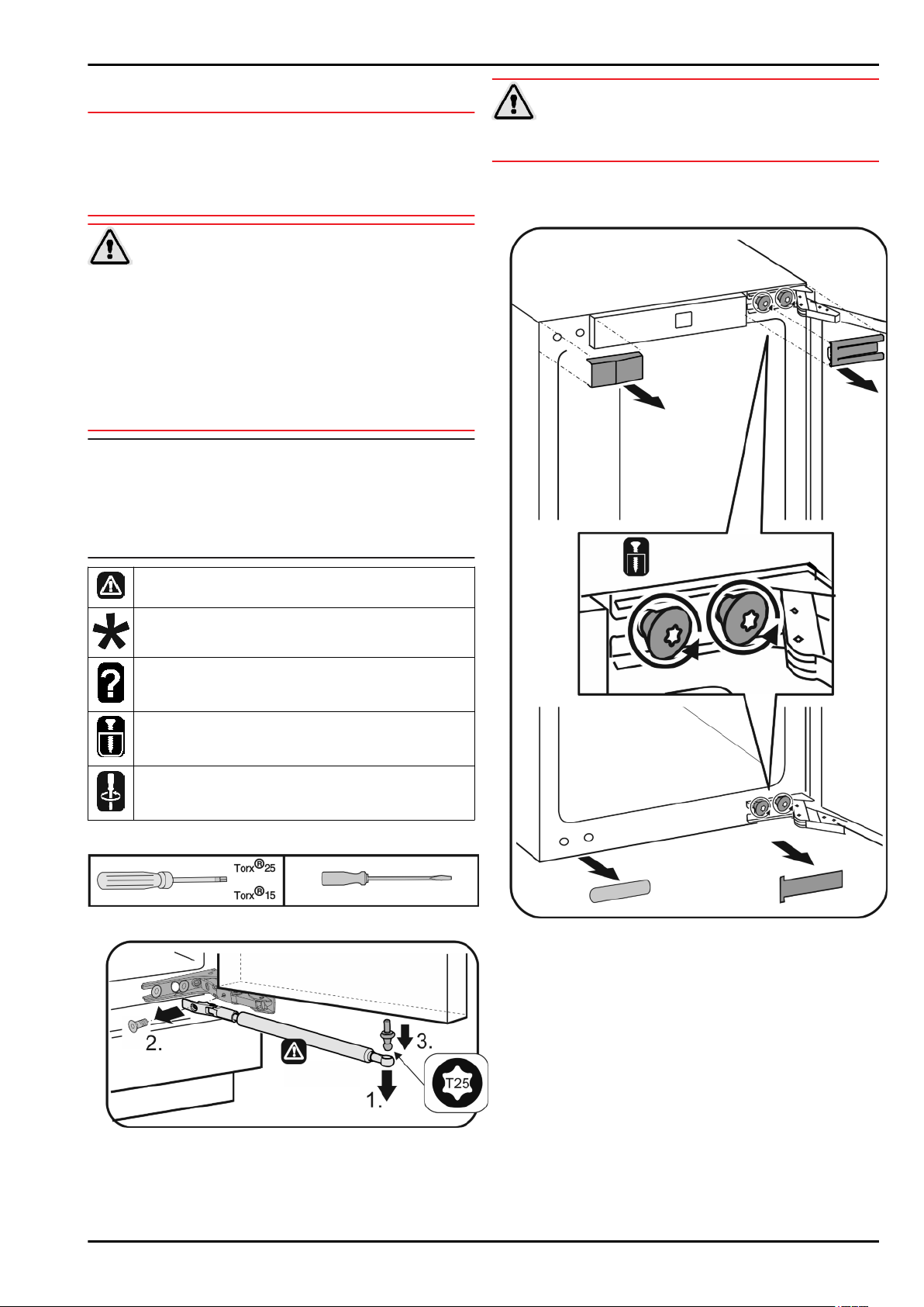
2.5 Changing the door direction*
NOTICE
Risk of damage due to colliding doors!
When assembling an appliance with the appliance name
beginning with S... next to another appliance:
Install the appliances so that the doors open outwards.
u
Switch the door hinges, if necessary.
Risk of injury if soft stop contracts!
CAUTION
Carefully remove the soft stop mechanism.
u
Remove the closing damper: Remove the closing dampers
u
from the ball studs (1), unscrew the bracket (2). Use a
screwdriver to remove the ball studs (3).
Risk of injury due to the door dropping out!
WARNING
If the fastening parts are not screwed into place firmly enough,
the door may drop out. This may lead to severe injuries. What is
more, the door may not close and therefore the appliance may
fail to cool properly.
Screw the hinges and the ball journal of the soft stop mecha-
u
nism firmly into place, with 4 Nm.
Screw the holder of the soft stop mechanism firmly into
u
place, with at least 3 Nm.
Check all of the screws and retighten if necessary.
u
Note
You can change the direction of the door only if there is enough
room at the top to remove the hinge fixing brackets and refit
them on the opposite side. This is rarely the case once the unit
is installed in the recess.
Change the direction of the door before the appliance is
u
installed.
Risk of injury here! Follow the safety notes!
These instructions apply to a range of models. Follow
this step only if it applies to your appliance.
Choose from one of these options.
Just loosen the screws, do not remove.
Check the screw fittings and tighten if necessary.
Tools required:
Fig. 3
Fig. 4
Fig. 5
Remove the covers.
u
Just loosen the screws on the hinges, do not remove.
u
Remove the screws only once you have removed the door
u
with its hinges.
4 * Depending on model and options
Page 5

Putting into operation
Fig. 6
CAUTION
Risk of injury if hinges fold!
Leave hinges open.
u
Remove the door: Slide the door towards you and out, then
u
lift off the brackets and put aside.
Fig. 7
Move the hinges.
u
Fig. 8
Move the fixing bracket to the opposite side.
u
* Depending on model and options 5
Page 6

Putting into operation
2.6 Installing the appliance in the recess
Fig. 9
Refit the door: Hang the door with its hinges and tighten the
u
screws.
Fire hazard from short-circuiting!
When pushing the appliance into the recess, take care not to
u
crush, jam or damage the mains power cable.
Do not operate the appliance with a defective mains power
u
cable.
NOTICE
WARNING
Risk of damaging the hinges!
If when being pushed the appliance is held by the door, the
hinges could be damaged.
When pushing or otherwise moving the appliance, always
u
hold it by the main body.
For installation in the recess, the following accessories
are available from Customer Service:
Kit to limit the door opening angle to
90°
Risk of injury here! Follow the safety notes!
Please take note of the information in the symbols key
u
during installation.
2.7 Installation
Fig. 10
Refit the closing dampers: Screw in the ball studs (1),
u
tighten the bracket (2) and hang the closing dampers in the
ball studs.
Fig. 11
Check all screws and tighten if necessary.
u
Refit the covers.
u
All the assembly components accompany the appliance.
Fig. 12
Ensure that the following tools are to hand:
Cordless Torx® screwdriver 15, 25
q
Spanner 13
q
Screwdriver Torx® 15
q
Flat-blade screwdriver 6
q
Allen key 8
q
Tape measure
q
Pencil
q
String
q
Spirit level
q
Pay attention that the socket is readily accessible.
Ventilation requirements
6 * Depending on model and options
Page 7

Fig. 13
The air flow cavity must be at least 200 cm².
The unit's energy consumption will increase if there is insuffi-
cient air flow.
Putting into operation
2.7.1 Installing the appliance
If already in place, pull the plinth panel forwards.
u
Detach the connecting cable from the rear of the appli-
u
ance, removing the cable holder at the same time
because otherwise there will be vibratory noise!
Lay the connecting cable with
u
the help of a string in such a
way that the appliance can be
easily connected after fitting.
NOTICE
Risk of harm to flooring susceptible to damage!
Place a strip of cardboard under the height-adjustable feet,
u
approx. 10 cm x 60 cm, one at either side. Cut the strips out
of the packaging. For opening heights less than 826 mm,
use strips of a firm but thin material.
After the appliance has been slid in, remove the strips.
u
Fig. 15
Fig. 16
Fig. 14
Fix the foam pad in the middle of the plinth panel.
The foam pad is used to separate the incoming and outgoing
air flow and allows sufficient ventilation.
Type of fixing on the kitchen unit
Side fixing
Base frame under a hard worktop, such as granite.
q
The appliance is lower than the work surface when the
q
adjusting feet are fully extended.
Pre-requisite: Side unit wall available for screw connection.
q
Top fixing
The appliance is slightly braced under the work top when
q
the adjusting feet are fully extended.
No granite plate.
q
Top fixing
Fig. 17
Insert the bracket into the holder on the top of the unit and
u
bend towards the front.
Slide the unit into the recess and level, see Levelling the
u
appliance.
* Depending on model and options 7
Page 8

Putting into operation
Fig. 18
Bend both brackets at one end before installation. Insert the
u
straight edge into the holder on the top of the unit and bend
towards the front.
Slide the unit into the recess and level, see Levelling the
u
appliance.
Levelling the appliance
Place the foam pad in the plinth panel – this is essential for
u
separating air flows!
Fig. 20
Unscrew the rear adjusting feet using a screwdriver and
u
undo the front adjusting feet using a no. 8 Allen key alternately until the unit sits just under the worktop.
Use a spirit level to level the unit.
u
The gap from the front edge of the cabinet wall to the appli-
w
ance should be 41.5 mm on both sides.
Should there be no unit side wall, align it with the work top.
w
For units with door stop components (knobs, sealing
lips etc.):
Deduct the extra dimension (depth of the door stop compo-
u
nents) from the 41.5 mm depth of insertion.
Unscrew the rear adjusting feet using a screwdriver and
u
undo the front adjusting feet using a no. 8 Allen key (if the
adjusting feet are retracted) or a screwdriver (if the adjusting
feet are extended) alternately as far as they will go. The
maximum adjustment range is 60 mm.
The appliance is aligned upright.
w
The appliance is slightly braced between the floor and the
w
work top.
Fig. 19
Fig. 21
Fit the plinth panel (2) without securing.
u
Position the unit door and the unit plinth panel for testing.
u
If plinth panel (2) is visible, pull it forward until the front edge
u
of the ventilation grid and the unit plinth panel are in line.
-or-
If the plinth panel (2) is hidden, push it right back.
u
Ensure that the ventilation slots are completely free: If
u
necessary, cut some off the height of the unit plinth panel
(U).
Adjust the bar height (V) under the plinth panel (2) along the
w
recess width (W).
Fig. 22
Fit and secure the plinth panel: Hold the plinth panel and
u
insert the catch.
Fix the unit plinth panel.
u
To secure appliance in the recess:
8 * Depending on model and options
Page 9

Fig. 23
If affixing the unit under a worktop, use 2 screws to secure
u
the fixing bracket under the worktop.
Putting into operation
Attach fastening crosspiece
u
unit door using the assembly aids
Align the crosspiece
u
Distances to the outer edge are equal at the left and right.
w
For chipboard doors:
Secure the fastening crosspiece
u
screws
Fig. 26 (19)
For frame and panel doors:
Secure the fastening crosspiece
u
Fig. 26 (19)
Raise the assembly aids
u
and insert them into the adjacent openings.
at the edge.
Fig. 26 (11)
.
Fig. 26 (11)
to the inside of the
Fig. 26 (12)
in the middle of the door.
Fig. 26 (11)
Fig. 26 (11)
Fig. 26 (12)
for removal, turn them
.
with at least 6
with 4 screws
Fig. 26
Fig. 24
If attaching the unit at the side, screw the fixing bracket into
u
the recess with one screw on each side.
2.7.2 Fitting the unit door
Fit the handle on the unit door.
u
Check 8 mm presetting. (Distance between appliance door
u
and lower edge of crosspiece)
Push up assembly aids
u
Lower edge ▲of the assembly aid = top edge of the unit
door to be fitted.
Unscrew fastening crosspiece
u
locknuts
Fig. 25 (10)
Fig. 25 (12)
.
to unit door height.
Fig. 25 (11)
by undoing the
Fig. 25
Attach the unit door to the adjusting bolts
u
loosely screw the locknuts
Close the door.
u
Check the gap between the door and the surrounding unit
u
doors.
To laterally align the door: push unit door in X direction.
u
To align the door vertically Y and in the lateral inclination:
u
adjust adjusting bolts
The unit door is flush and in alignment with the surrounding
w
unit fronts.
Tighten locknuts
u
To screw the unit door to the appliance door:
u
Drill pilot holes in the door of the unit (possibly make prelimi-
u
nary holes with a bradawl).
Screw the appliance door to the cabinet door using the fixing
u
bracket.
Fig. 27 (10)
Fig. 27 (10)
Fig. 27 (13)
.
with a screwdriver.
Fig. 27 (13)
onto them.
Fig. 27
and
Fig. 28
* Depending on model and options 9
Page 10

Putting into operation
Fig. 29
Align the cabinet door to the height marked Z: loosen the
u
screws at the top and bottom of the door, then adjust the
door.
Open the door to approx 45° so you can easily access the
u
screws under the door.
Do not allow knobs and sealing lips
u
to make contact - important for function!
Allow an air gap of 2 mm between
u
the unit door and the body of the
unit.
The packaging is made of recyclable materials:
corrugated board/cardboard
-
expanded polystyrene parts
-
polythene bags and sheets
-
polypropylene straps
-
nailed wooden frame with polyethylene panel*
-
Take the packaging material to an official collecting point.
u
2.9 Connecting the appliance
NOTICE
Failure to connect properly
Damage to the electronics.
Do not use a standalone inverter.
u
Do not use an energy saving plug.
u
Failure to connect properly
Fire hazard.
u
u
The type of current (alternating current) and voltage at the
installation site have to conform with the data on the type plate
(see Appliance at a glance).
The socket must be properly earthed and fused. The tripping
current for the fuse must be between 10 A and 16 A.
The socket must be easily accessible so that the appliance can
be quickly disconnected from the supply in an emergency. It
must be outside the area of the rear of the appliance.
u
u
WARNING
Do not use an extension cable.
Do not use distributor blocks.
Check the electrical connection.
Plug in the power plug.
Fig. 30
Check the fit of the door and readjust if necessary.
u
Tighten all screws.
u
Tighten lock nuts
u
sure you counterhold the adjusting bolts
screwdriver.
Fig. 30 (10)
with a no. 13 Allen key, making
Fig. 30 (13)
with a
Fig. 31
Fit the top cover and click into place.
u
Check the following points to ensure the appliance is fitted
properly. Failure to do so may lead to icing, condensate forming
and malfunction:
The door has to close properly
w
The unit door must not butt against the unit body
w
2.8 Disposing of packaging
Danger of suffocation due to packing material and plastic film!
Do not allow children to play with packing material.
u
10 * Depending on model and options
WARNING
Page 11

Putting into operation
* Depending on model and options 11
Page 12

Liebherr-Hausgeräte Ochsenhausen GmbH
Memminger Straße 77-79
88416 Ochsenhausen
Deutschland
home.liebherr.com
 Loading...