

Liebherr SICBN3356LH Installation Guide
Installation instructions
Combined fridge-freezer for integrated use, door-on-door
170215
(S)IC.../ (S)ICB.../ ICU... ... LC/ LP
7085634 - 02
General safety information
Contents
1 General safety information................................... 2
2 Transporting the appliance................................... 2
3 Installing the appliance......................................... 2
4 Appliance dimensions........................................... 3
5 Recess dimensions............................................... 3
6 Unit door................................................................. 4
7 Ventilation of the kitchen unit............................... 4
8 Changing over door hinges.................................. 5
9 Water connection................................................... 5
10 Installing the appliance in the recess.................. 6
11 Disposing of packaging........................................ 6
12 Connecting the appliance..................................... 6
The manufacturer works constantly on the further development
of all the types and models. Therefore please understand that
we have to reserve the right to make design, equipment and
technical modifications.
To get to know all the benefits of your new appliance, please
read the information contained in these instructions carefully.
The instructions apply to several models. Differences may
occur. Text relating only to specific appliances is marked with
an asterisk (*).
Instructions for action are marked with a , the results of
action are marked with a .
1 General safety information
-
Only install, connect and dispose of the appliance according to the instructions. Take
particular note of “Recess dimensions” (see 5)
and “Ventilation of the kitchen unit” (see 7) .
-
The socket must be easily accessible so that
the appliance can be quickly disconnected
from the supply in an emergency. It must be
outside the area of the rear of the appliance.
DANGER identifies a situation involving direct
danger which, if not obviated, may
result in death or severe bodily
injury.
WARNING identifies a dangerous situation
which, if not obviated, may result in
death or severe bodily injury.
CAUTION identifies a dangerous situation
which, if not obviated, may result in
minor or medium bodily injury.
NOTICE identifies a dangerous situation
which, if not obviated, may result in
damage to property.
Note identifies useful information and tips.
2 Transporting the appliance
CAUTION
Risk of injury and danger of damage as a result of incorrect
transport!
Transport the appliance in a packed condition.
u
Transport the appliance upright.
u
Do not transport the appliance without assistance.
u
3 Installing the appliance
WARNING
Risk of fire due to short circuit!
If the mains cable/connector of the appliance or of another
appliance touch the rear of the appliance, the mains cable/
connector may be damaged by the appliance vibrations,
leading to a short circuit.
Stand the appliance so that it is not touched by connectors
u
or main cables.
Do not plug the appliance or any others into sockets located
u
near the rear of the appliance.
WARNING
Fire hazard due to dampness!
If live parts or the mains lead become damp this may cause
short circuits.
The appliance is designed for use in enclosed areas. Do not
u
operate the appliance outdoors or in areas where it is
exposed to splash water or damp conditions.
Only use the appliance when it is installed.
u
WARNING
Fire hazard due to refrigerant!
The refrigerant R 600a is environmentally friendly but flammable. Escaping refrigerant may ignite.
Do not damage the piping of the refrigeration circuit.
u
WARNING
Fire hazard and danger of damage!
Do not place appliances emitting heat e.g. microwaves,
u
toasters etc. on the appliance!
NOTICE
Risk of damage from condensation!
If your appliance is not a Side-by-Side (SBS) appliance:
do not install the appliance directly next to another fridge/
u
freezer.
If your appliance is a Side-by-Side (SBS) appliance:
install the SBS fridge-freezer combination according to the
u
accompanying sheet.
In the event that the appliance is damaged, contact the
q
supplier immediately before connecting to the mains.
The floor at the site must be flat and level.
q
Do not install the appliance in a location where it is exposed
q
to direct radiation of the sun, next to a cooker, heater and
similar.
Do not install the appliance alone: it is best to work together
q
with two or more people.
2 * Depending on model and options
The more R 600a refrigerant there is in the appliance, the
q
larger the room in which the appliance is standing needs to
be. In rooms that are too small, a flammable mix of gas and
air may be created if there is a leak. According to the EN
378 standard, every 11 g of R 600a refrigerant requires at
least 1 m3 space in the room for the appliance. The amount
of refrigerant in your appliance is on the type plate inside the
appliance.
If the appliance is installed in a very damp environment,
q
condensed water may form on the outside of the appliance.
Always make sure that there is good ventilation - both at air
inlet and outlet - at the site of installation.
If the transport lock is inserted on the door:
Pull off red transport lock.
u
If the transport lock is screwed onto the door:
Unscrew red transport lock.
u
Close the freed retaining hole
with plugs (60).
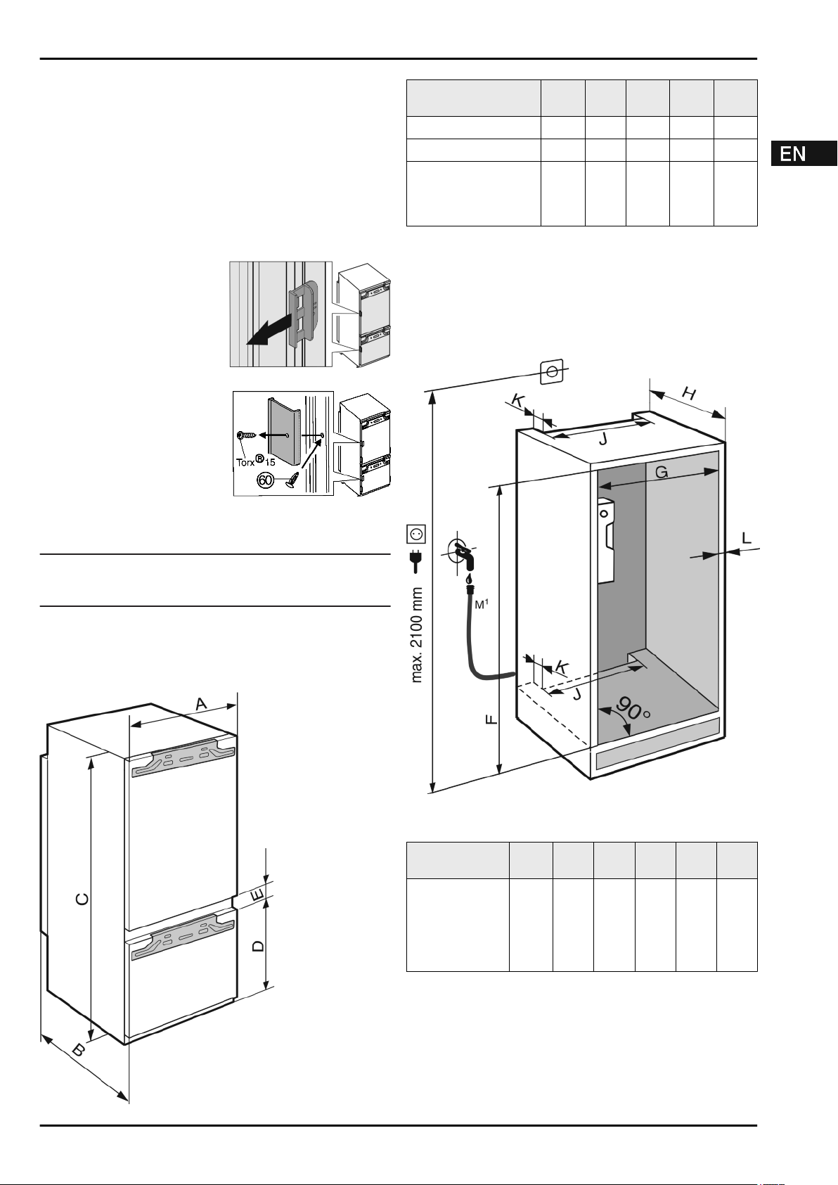
Appliance dimensions
A
(mm)B(mm)C(mm)D(mm)E(mm)
ICP 29.. 559 544 1572 549 15
ICBP 32.. 559 544 1770 549 15
ICU 33.., ICUN 33..,
ICP 33.., ICNP 33..,
ICN 33.., SICN 33..,
ICBN 33.., SICBN 33..
559 544 1770 695 15
5 Recess dimensions
The appliance is built-in and therefore completely enclosed by
a kitchen unit. The kitchen unit concerned must be built exactly
to the prescribed dimensions and allow for sufficient ventilation, both at air inlet and outlet, to ensure proper appliance
operation.
After installation:
Remove protective films, adhesive tapes and transport lock
u
parts etc.
Note
Clean the appliance (see Operating Instructions,
u
Chapter "Cleaning the appliance").
4 Appliance dimensions
Fig. 2
M1) : For N3366 only (see 9)
F
(mm)G(mm)H(mm)J(mm)K(mm)L(mm)
ICP 29.. 1574
—
1590
560
—
570
min.
550,
reco
mme
nded
560
min.
500
min.40max.
19
Fig. 1
* Depending on model and options 3
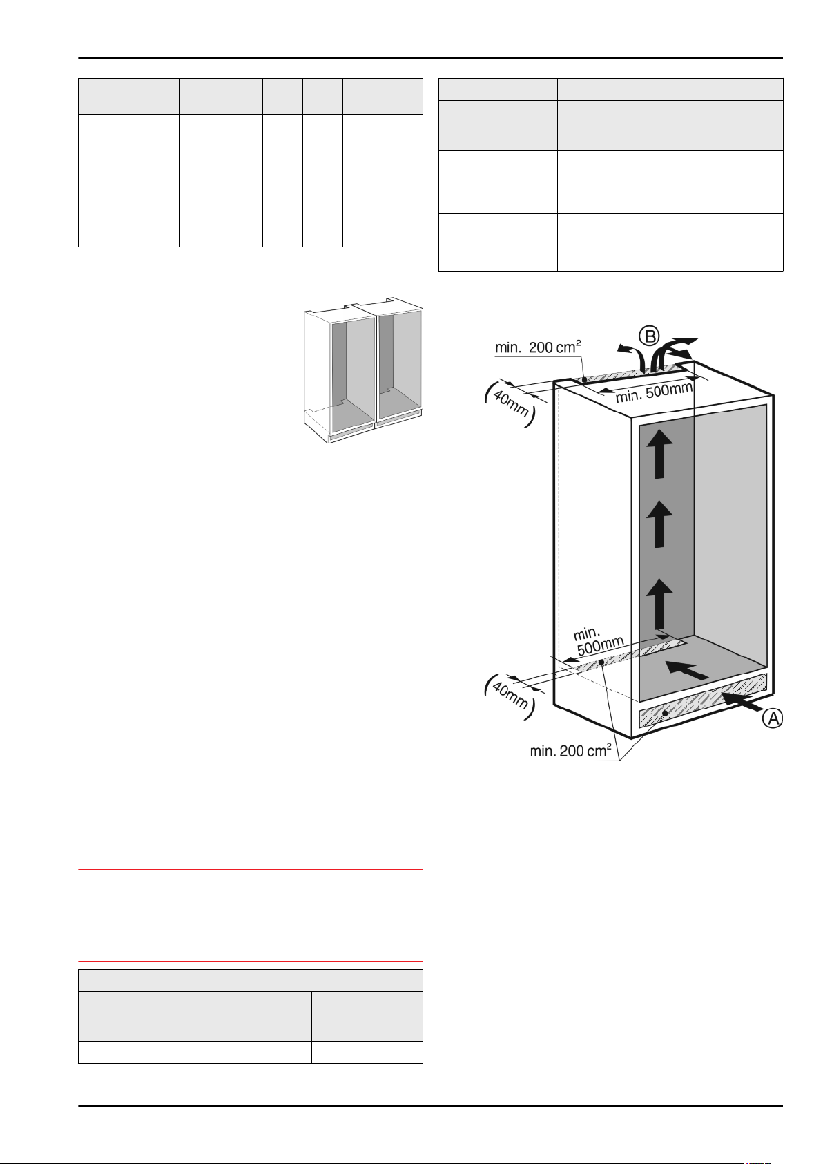
Unit door
F
(mm)G(mm)H(mm)J(mm)K(mm)L(mm)
ICU 33..,
ICUN 33..,
ICP 33..,
ICNP 33..,
ICN 33..,
SICN 33..,
ICBP 32..,
ICBN 33..,
SICBN 33..
The specified energy consumption applies to a unit depth of
560 mm. The appliance will work properly at a unit depth of 550
mm, but at a slightly higher energy consumption.
In the case of Side-by-Side installa-
u
tion, two appliances next to one
another, build the appliances into
separate kitchen units.
Check the wall thickness of the adjoining cabinets: it must
u
be min. 16 mm.
Only install the appliance in robust, stable kitchen units.
u
Secure the units against tipping.
Align the kitchen unit using a spirit level and marking square
u
and if necessary compensate with shims.
Ensure that the floor and walls of the unit are at right angles
u
to one another.
1772
—
1788
560
—
570
min.
550,
reco
mme
nded
560
min.
500
min.40max.
19
Appliance type Maximum unit door weight (kg)
Refrigerator
compartment
door
ICU 33.., ICUN 33..,
ICP 33.., ICN 33..,
SICN 33..,
ICNP 33..
ICBP 32.. 19 12
ICBN 33..,
SICBN 33..
14 12
20 12
Freezer compartment door
7 Ventilation of the kitchen unit
6 Unit door
Two doors are required for this kitchen unit: the upper for the
-
refrigerator and the lower for the freezer compartment.
The doors must be minimum 16 mm and maximum 19 mm
-
thick.
When both doors are closed, the gap between the upper
-
and lower door must be at least 3 mm high.
The gap between unit doors must be at the same level as
-
the gap between the appliance doors.
There must be a gap of minimum 3 mm in height between
-
the door and the unit door located above it (if one exists).
The width of the unit doors depends on the style of the
-
kitchen and on the gap size between the door panels of the
cabinet. Generally, there should remain a vertical gap of
3 mm between the unit doors.
The top edges of the upper and lower doors should be on a
-
level with the doors of the adjoining cabinet (or cabinets), if
there are other cabinets.
The unit doors must be planar and mounted stress-free.
-
NOTICE
Risk of damage from over-heavy unit door!
If the unit door is too heavy, damage to the hinges and resulting
impairment of function cannot be excluded.
Before mounting the unit door, make sure that the door does
u
not exceed the approved unit door weight.
Appliance type Maximum unit door weight (kg)
Refrigerator
compartment
door
ICP 29.. 13 12
Freezer compartment door
There must be an effective ventilation shaft of at least
-
200 cm2 per appliance at the air inlet
Fig. 3 (B)
The principle applies that the larger the ventilation shaft, the
-
more energy-saving the operation of the appliance.
The depth of the ventilation shaft at the back of the cabinet
-
must be min. 40 mm.
vent.
Fig. 3 (A)
and outlet
Fig. 3
4 * Depending on model and options
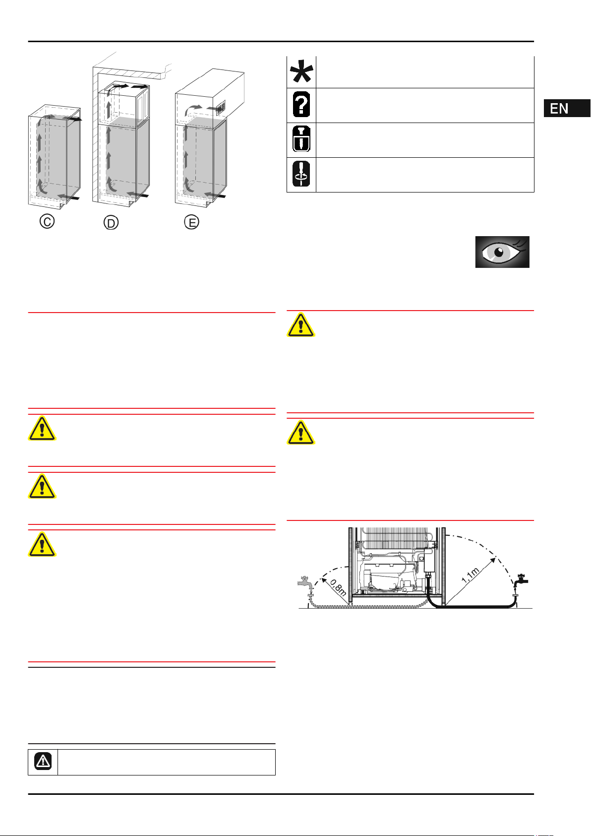
The upper ventilation shaft can either be positioned directly
-
above the appliance with an optional ventilation grille
Fig. 4 (C)
an air outlet opening in a false ceiling
, close to the ceiling above the unit
Fig. 4 (E)
Fig. 4 (D)
.
Fig. 4
or as
Changing over door hinges
The instructions apply to several models. Only carry
out this step if it is relevant for your appliance.
Choose between the alternatives given.
Loosen the screws only, do not undo them all the way.
Check the screws and tighten if necessary.
While changing over the door hinges, observe the safety
u
instructions above and also the information in the symbols
key.
Change the hinges over as shown at the end
of the book.
8 Changing over door hinges
NOTICE
Risk of condensation damage for Side-by-Side appliances!
Certain appliances can be set up as Side-by-Side combinations (two appliances next to each other).
If your appliance is a Side-by-Side (SBS) appliance:
Set up the SBS combination in accordance with the
u
enclosed document.
If the positioning of the devices is stipulated:
Do not change the door hinges over.
u
CAUTION
Risk of injury if soft stop contracts!
Carefully remove the soft stop mechanism.
u
CAUTION
Risk of injury if hinges fold!
Leave hinges open.
u
WARNING
Risk of injury due to the door dropping out!
If the fastening parts are not screwed into place firmly enough,
the door may drop out. This may lead to severe injuries. What
is more, the door may not close and therefore the appliance
may fail to cool properly.
Screw the hinges and the ball journal of the soft stop mecha-
u
nism firmly into place, with 4 Nm.
Screw the holder of the soft stop mechanism firmly into
u
place, with at least 3 Nm.
Check all of the screws and retighten if necessary.
u
Note
The door hinges can only be changed over if there is sufficient
space towards the top to pull out the hinge mounting bracket
and to mount it again on the other side. This is generally not the
case after installation in the recess.
Change the hinges over before the appliance is installed in
u
the recess.
There is a risk of injury during this stage! Please
observe the safety instructions!
9 Water connection*
WARNING
Danger of electric shock!
Disconnect the appliance by unplugging it before you
u
connect it to the water line.
Shut off the water supply before you connect the water feed
u
lines of the IceMaker.
The connection to the drinking water system may be carried
u
out only by a qualified gas fitter and plumber.
WARNING
Risk of poisoning!
The water quality has to comply with the drinking water ordi-
u
nance of the respective country (e.g. 98/8
Connect to the drinking water supply only.
u
The IceMaker serves exclusively for making ice cubes in
u
household quantities and has to be operated with water suitable for the purpose.
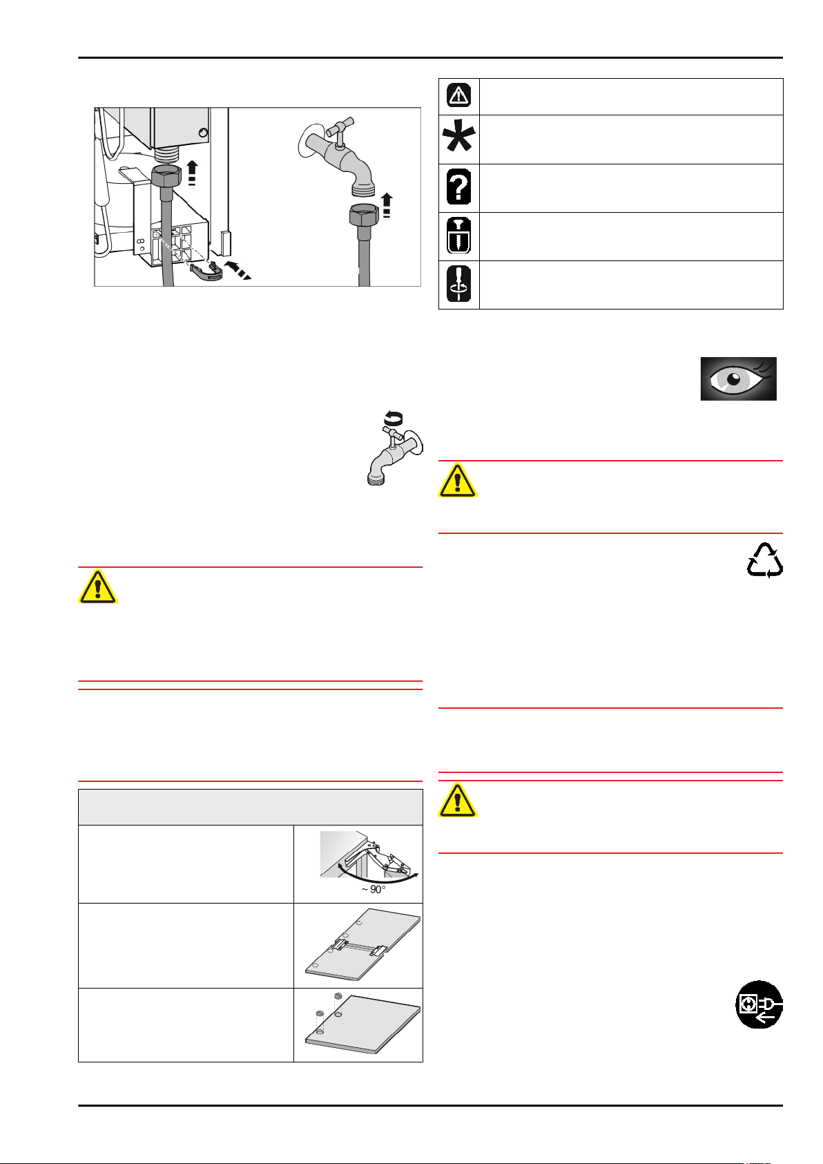
Fig. 5
- The water pressure has to be between 0.15 MPa and
0.6 MPa (1.5 bar - 6 bar).
- The water supply to the appliance must be via a cold water
pipe which withstands the operating pressure and complies
with the hygiene regulations.
Use the accompanying stainless steel hose (1.5 m). Do not
reuse old hoses. A 3 m hose is available from the customer
service department and has to be fitted by an expert.
In the hose connecting piece is a sieve with seal.
- Between the hose and the domestic water connection there
has to be a stopcock to interrupt the water supply in case of
need.
- All the fixtures and fittings used for water supply have to
comply with the applicable regulations of the respective
country.
* Depending on model and options 5
Installing the appliance in the recess
- Do not damage or kink the water inlet pipe when installing
the appliance.
Fig. 6
The solenoid valve is at the bottom back of the appliance. It
has a metric R3/4 connecting thread.
Connect the stainless steel hose:
Connect the fitting with the strainer to the stopcock.
u
Connect the other end of the hose to the solenoid valve.
u
Fix the stainless steel hose to the housing with the locking
u
hook.
Open the stopcock of the water supply and
u
check that the entire water system is leakproof.
Before initial use:
Have the water pipe bled of air by the proper
u
expert.
There is a risk of injury during this stage! Please
observe the safety instructions!
The instructions apply to several models. Only carry
out this step if the appliance is equipped with the
corresponding feature.
Choose between the alternatives given.
Loosen the screws only, do not undo them all the way.
Check the screws and tighten if necessary.
Please take note of the information in the symbols key
u
during installation.
Install the appliance into the recess as shown
at the end of the book.
11 Disposing of packaging
10 Installing the appliance in the recess
WARNING
Fire hazard from short-circuiting!
When pushing the appliance into the recess, take care not
u
to crush, jam or damage the mains power cable.
Do not operate the appliance with a defective mains power
u
cable.
NOTICE
Risk of damaging the hinges!
If when being pushed the appliance is held by the door, the
hinges could be damaged.
When pushing or otherwise moving the appliance, always
u
hold it by the main body.
For installation into the recess, the following accessories are available from Customer Services:
Set for limiting the door opening angle
to 90°
Set for mounting divided unit fronts
Set with cover for concealed hinges
WARNING
Danger of suffocation due to packing material and plastic film!
Do not allow children to play with packing material.
u
The packaging is made of recyclable materials:
corrugated board/cardboard
-
expanded polystyrene parts
-
polythene bags and sheets
-
polypropylene straps
-
nailed wooden frame with polyethylene panel*
-
Take the packaging material to an official collecting point.
u
12 Connecting the appliance
NOTICE
Risk of damage to the electronic control system!
Do not use stand-alone inverters (conversion of d.c. to a.c./
u
three-phase) or energy saving plugs.
WARNING
Fire and overheating hazard!
Do not use extension cables or multiple socket outlets.
u
The type of current (alternating current) and voltage at the
installation site have to conform with the data on the type plate
(see Appliance at a glance).
The socket must be properly earthed and fused. The tripping
current for the fuse must be between 10 A and 16 A.
The socket must be easily accessible so that the appliance can
be quickly disconnected from the supply in an emergency. It
must be outside the area of the rear of the appliance.
Check the electrical connection.
u
Plug in the power plug.
u
6 * Depending on model and options
 Loading...