

Page 1
H
P
S
SERVICE MANUAL
English
Cod. 273000
Rev. 16.02.2006
Issued by T.D.Service
Page 2

Page 3

Caution
Recommendations:
S the manual is retained for the entire service life of the machine;
S the user reads the manual carefully before carrying out any operations on the machine;
S the machine is used exclusively for the purpose for which it is intended; incorrect use of the machine shall release the
manufacturer from any liability.
This manual has been prepared to enable the end ---user to carry out only the operations that can made with the panels
closed. Any operations that require the opening of doors or equipment panels must be carried out only by qualified
personnel.
Each machine is equipped with an electric isolating device which allows the operator to work in conditions of safety. This
device must always be used to eliminate risks during maintenance (electric shocks, scalds, automatic restarting, moving
parts and remote control).
The panel key supplied with the unit must be kept by the person responsible for maintenance.
For identification of the unit (model and serial no.) in case of the necessity for assistance or spare parts, read the identification
label placed on the outside and inside of the unit.
IMPORTANT:
1
4
7
10
12
14
18
19
21
23
25
This manual may be subject to modification; for complete and up---to---date information the user should
always consult the manual supplied with the machine.
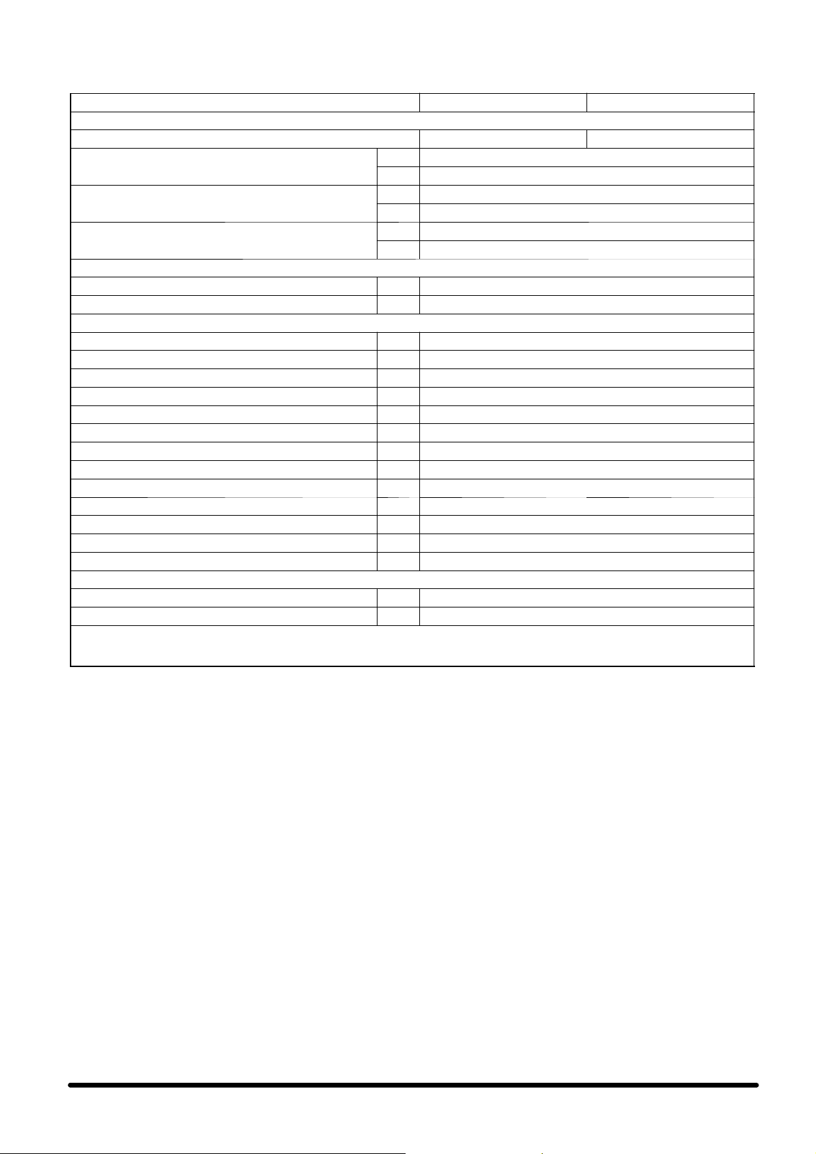
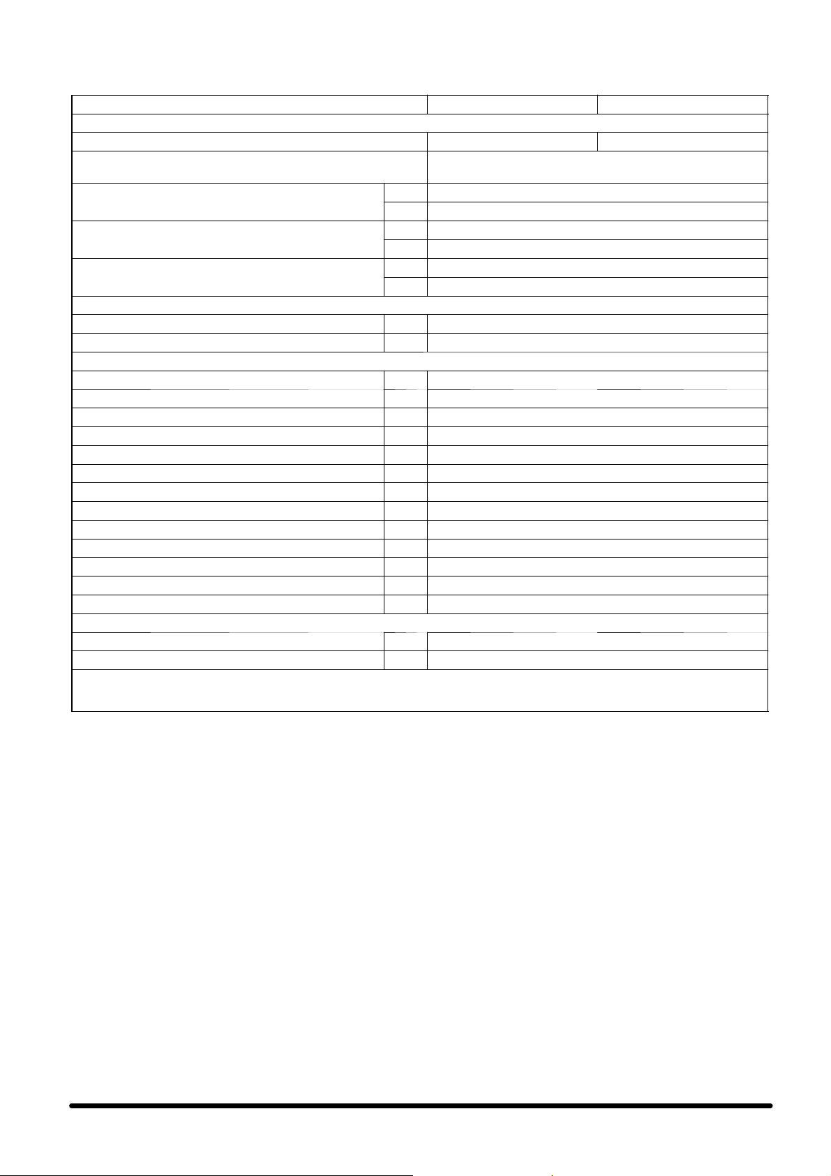
Attention: data relevant to the unit supplied
is indicated on the inboard label (see the blank facsimile below).
Data in the manual is referred to standard conditions
and can be modified without any advance notice.
POS. DESCRIPTION
1 Compressor Full Load Ampere [A]
2 Compressor Locked Rotor Ampere [A]
3 Compressor quantity
4 Evaporator fan Full Load Ampere [A]
5 Evaporator fan Locked Rotor Ampere [A]
6 Evaporator fan quantity
7 Condenser fan Full Load Ampere [A]
8 Condenser fan Locked Rotor Ampere [A]
9 Condenser fan quantity
10 Electrical heating Ampere
11 Electrical heating steps
12 Humidifier Ampere
13 Steam production capacity
14 Max. unit AC Ampere
15 Max. unit DC Ampere
16 Rated peak withstand current
17 Rated short --- time current
18 Refrigerant type
19 High pressure switch Stop
20 High pressure switch Restart
21 Low pressure switch Stop
22 Low pressure switch Restart
23 Min. room operation temperature
24 Max. room operation temperature
25 Min. room operation humidity
26 Max. room operation humidity
27 Max. refrigeration circuit pressure
15
11
2
5
8
3
6
9
13
16
17
20
22
24
26
27
Page 4

Index
1 -- Preliminary operations pag. 1...............................................................
1.1 --- Foreword pag. 1.......................................................................................
1.2 --- Check operating limits pag. 1............................................................................
1.3 -- - Check sound pressure levels pag. 1.......................................................................
1.4 --- Conditioner inspection pag. 1............................................................................
1 . 5 --- Tr a n s p o r t pag. 1.......................................................................................
1 . 6 --- S e a l i n g t h e r o o m pag. 1.................................................................................
1.7 --- Servicing areas pag. 1..................................................................................
2 -- Installation pag. 1..........................................................................
2.1 --- Overall dimensions pag. 1...............................................................................
2.2 - -- Positioning the HPSE indoor unit pag. 1...................................................................
2.3 --- Positioning two inner HPSE units pag. 1...................................................................
2.4 --- Freecooling duct connections (optional) pag. 1.............................................................
2.5 --- Positioning the HPSC condensing unit pag. 2...............................................................
2.6 --- Refrigeration connections pag. 2.........................................................................
2.7 --- Condensate drain connection pag. 3......................................................................
2.8 --- Electrical connections and wiring diagram (supplied with the unit) pag. 3.......................................
2.9 --- User interface pag. 3....................................................................................
2.10 --- Emergency cooling version (EFC 48 VDC / 230 VAC) pag. 3.................................................
2.11 --- Electrical protection pag. 3..............................................................................
3 -- Starting and stopping pag. 3................................................................
3 . 1 --- F i r s t s t a r t --- u p ( o r af t e r a l o n g ha l t ) pag. 3..................................................................
3 . 2 --- S t a r t --- u p wi t h lo w o u t s i d e t e m p e r a t u r e (o n l y o n “ H P S C x x A / L” m o d e l s ) p a g . 3...................................
3 . 3 --- S e l f te s t pag. 3.........................................................................................
3.4 --- Starting and stopping pag. 4.............................................................................
4-- Operation pag. 4............................................................................
4.1 --- Control of the condenser fan speed (“HPSCxxA/L” models only) pag. 4.........................................
4.2 --- Emergency cooling (optional) pag. 4......................................................................
5-- Operatinglogic pag. 4......................................................................
5.1 --- Cooling only unit pag. 4.................................................................................
5.2 --- Unit with electric heating pag. 4..........................................................................
5.3 --- Unit with freecooling pag. 5..............................................................................
5.4 --- LAN local network management: Stand---by and Cascade modes pag. 5.......................................
5.5 --- Alarm control pag. 5....................................................................................
6 -- Settings pag. 5.............................................................................
7 -- Maintenance / Spare parts pag. 6............................................................
7.1 --- Routine maintenance pag. 6.............................................................................
7.2 --- Extraordinary maintenance pag. 6........................................................................
7.3 --- Dismantling the unit pag. 7..............................................................................
7.4 --- Spare parts pag. 7.....................................................................................
8 -- Appendix pag. 8............................................................................
8.1 --- Check the unit after the installation pag. 8..................................................................
Ta b l e s pag. 9....................................................................................
Drawings / Circuits pag. 17.......................................................................
Page 5
1 --- Preliminary operations
1.1 --- Foreword
This manual covers the installation, operation and maintenance of HPS air conditioners, which are composed of an
evaporating unit (HPSE), positioned in the room, and a condensing unit (HPSC), positioned outside.
IMPORTANT:
Also consult the manual for the microprocessor control.
1.2 --- Check operating limits
The units are designed to operate within specific working
ranges (see Tab. 1, Tab. 2, Tab. 3, Tab. 4, Tab. 5 and Tab. 6).
These limits are referred to new machines or for those that
have been correctly installed and serviced. The warranty
clauses are no longer valid for any damage or malfunction
that may occur during or due to operation outside the application range.
1.3 --- Check sound pressure levels
Tab. 1, Tab. 2, Tab. 3, Tab. 4, Tab. 5 and Tab. 6 show the internal (HPSE) and external (HPSC) sound pressure levels for
units in standard configuration, in continuous operation, at
2m from the front surface of the machine, 1m above base
level, and referred to free field conditions.
1.4 --- Conditioner inspection
On receiving the equipment immediately inspect its condition; report any damage to the transport company at once.
(e.g. acid vapours).
S Position the internal evaporating unit (HPSE) so as to op-
timise the indoor air distribution and avoid hot spots.
S Position the indoor unit preferably in the centre of the
room ceiling.
S Fix the unit to the ceiling by inserting expansion or
through clamps (in this case ensure the clamp is sealed)
using the slots on the two side brackets (see Fig. 2a,
Fig. 2b and Fig. 2c).
S Make sure the airflow circulates freely.
S To allow the servicing of the unit, the Service Area shown
in Fig. 2a and Fig. 2b, has to be left unobstructed (in
Fig. 2a the 300 mm minimum clearance from the back of
the evaporating unit is compulsory).
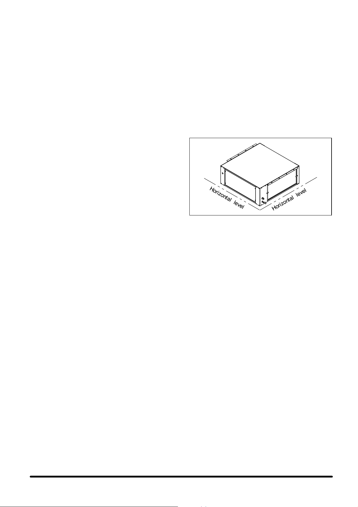
S Check if the unit is horizontal on both sides ”A” and
”B” (see. Fig. a).
Fig. a) Horizontal level control
“A” “B ”
1 . 5 --- Tr a n s p o r t
S Always keep the unit vertically upright and do not leave
it in the open.
S While carrying the unit, avoid exerting any pressure on
the upper corners of the package.
S Unpack the unit as close as possible to its installation
position. Once unpacked, avoid any impact to its internal
components.
1.6 --- Sealing the room
To create stable thermohygrometric conditions within the
room, proceed as follows:
S vapour seal the walls, floor and ceiling using an imperme-
able material;
S make sure that the room is airtight by sealing all gaps,
cable entries, etc.
1.7 --- Servicing areas
The unit must be provided with a suitable service area (see
Fig. 4).
All maintenance of the evaporating unit can be carried out as
shown in Fig. 2a and Fig. 2b.
Access to the condensing unit is provided by removable panels with screw fixings.
2 --- I n s t a l l a t i o n
CAUTION:
The evaporating unit (HPSE) must never be installed outdoors.
2.1 --- Overall dimensions
See Fig. 1a, Fig. 1b, Fig. 1c, Fig. 1d, Fig. 1e and Fig. 1f for
the overall dimensions of the evaporating unit (HPSE) and
external condensing unit (HPSC).
2.2 --- Positioning the HPSE indoor unit
S Unpack the unit as close as possible to the place where
it has to be installed. Once unpacked, avoid stress and
any impact to its internal components.
S The indoor unit can be installed in any indoor location
provided it is not exposed to an aggressive environment
2.3 --- Positioning two inner HPSE units
The ceiling installation of two units operating in the same
room must be carefully evaluated, considering the following
factors:
1) each intake side of the machine must be able to intake as
much as the other two;
2) possible ”Freecooling” function;
3) the thermal loads to be dissipated can be true hot air
flows hitting the intake sides of the machines: in this case,
the two intake sides of the two machines can be arranged
even at a short distance (up to 300 mm) to intake the thermal load where it is highest.
2.4 --- Freecooling duct connections
(optional)
The air conditioner may be supplied with an integrated Freecooling device (optional), which uses fresh air from outside to
cool the room without starting up the compressor. The device
provides the correct cooling capacity required, using a
motorised, modulating damper. In this case, the rear of the
unit is equipped with connections which draw in the outside
air, as follows:
S double circular holes, for 202 mm (HPSE 06) or 252 mm
( H P S E 0 8 --- 1 0 --- 1 2 --- 1 4 ) d i a m e t e r f l e x i b l e d u c t s t o b e
fixed with metal clamps;
S single rectangular hole with flange for 560x190 mm
(HPSE 06) or 600x250 mm (HPSE 08 --- 10 --- 12 --- 14) duct
(not supplied by Liebert --- HIROSS).
Inbothcases,theholesinthewallhavetobeprotectedby
rainproof grilles with a prefilter, to avoid water or foreign
bodies getting into the conditioner.
Outside air, taken into the room by the fan, is exhausted
through an overpressure damper, which is installed on the
wall of the room and protected by an external rainproof grille .
2.4.1 --- External air temperature probe installation
Install the external air temperature probe at the end of the
freecooling duct.
pag. 1
Page 6
IMPORTANT:
The bulb must be positioned as much outside as possible but
must not be exposed to direct sunlight or weather agents
such as rain or snow.The unit operation could be jeopardized
if these precautions are not applied.
2.5 --- Positioning the HPSC condensing
unit
Available condensing unit versions:
HPSC “0”: base version
HPSC “A”: advanced version
HPSC “L”: long piping version (see Fig. 12)
S The condensing unit must be positioned outside to en-
able its cooling (see Fig. 3).
S It is connected to the air conditioner through the re-
frigerant pipelines. Keep the refrigerant lines as short
as possible and anyway follow the indications in
Tab. a, Tab. b, Fig. 11 and Fig. 12, considering that in stallations with equivalent length of the refrigerant
pipelines over 10 m are possible only for HPSCxxL
units.
S Install the condensing unit in a level position, able to bear
its weight and vibrations and away from contaminating
agents (e.g. dust, leaves) to ensure the best efficiency
over time. Avoid any place containing flammable gases.
S If different locations are available, preferably install the
condensing unit in places sheltered from rain, with suitable air circulation and not subject to strong sun exposure; the latter precaution enables performance optimisation and compliance with the operating limits. For installationsinplaceswithwindspeedsover5m/s(e.g.
building tops) consider that such conditions can offer resistance to the air outlet from the condensing unit, reducing the air delivery and thus the heat exchange capacity,
or they can make the fan run too fast jeopardizing its operation, as well as increasing the hazard of the machine tilting if it is not properly fixed. To lessen the problem of
strong gusts of wind, position the condensing unit close
to a wind barrier (e.g. building or enclosing wall) and in
a direction perpendicular to the flow of the discharge air.
To prevent tilting ensure that the unit is securely fixed, if
necessary through additional supports or tie---rods, thus
ensuring stability even in case of earthquakes. Position
the unit so that the ejected hot air and the sound
emissions do not disturb people. In case of snow, make
sure that the unit is not completely covered and that the
inlet sections are always clear. To enable sufficient air delivery through the unit/s and to have sufficient space for
maintenance, it is necessary not to obstruct the air inlet
and discharge sections of the condensing unit, positioning it, or several machines, to maintain the minimum service areas and distances indicated in Fig. 4, for some
possible installation configurations.
S Fig. 3 shows some examples of how to install the con-
densing unit. For wall --- mounted installation the condensing unit can be supplied with an optional mounting
kit, comprising a pair of galvanised steel angle brackets,
painted with RAL9002 polyester powder with a smooth
finish; suitable elastomer anti---vibration mounts and
stainless steels fixings, including anchor screws for wall
fastening (see Fig. 2d).
NOTE: The anchor screws included in the kit are to be
used only when fastening the brackets to a concrete or
brick wall (including hollow bricks). Do not use them on
sandwich walls (e.g. a container) or walls of unknown
composition. In these cases the most suitable fastening
system for the special material must be used. If the above
mentioned optional kit is not used, suitable anti --- vibration mounts must always be fitted between the condensing unit and the mounting brackets, to avoid the transmission of vibrations. Also make sure that the brackets
used are suitable for supporting the condensing unit in all
conditions (e.g. in case of temporary abnormal loads on
the unit).
2.6 --- Refrigeration connections
THIS OPERATION MUST BE CARRIED OUT BY AN EXPERT TECHNICIAN.
The condensing and evaporating units are pre---charged
with Nitrogen and have to be charged with refrigerant (see
Chap. 7.2.2 – Refrigerant charging).
a) Pipeline positioning
Connect the air conditioner to the condensing unit using re-
frigerant lines in hard or soft copper.
S Limit the number of pre --- shaped bends. If this is not
possible, every bend must have a radius of at least 100
mm.
S The gas line must be insulated.
S The liquid line must be kept away from heat sources. If
this is not possible it has to be insulated.
S If the condensing unit is located above the evaporating
unit, the last segment of the suction line (insulated pipework) must be inclined towards the condensing unit.
If, on the other hand, the condensing unit is located below the
air conditioner it is advisable to create a trap on the suction
line.
Tab. a --- HPSCxx0/A: external standard
Model
HPS060/A 2m<L≤10m φ 16 x 1 φ 12 x 1 1% with 10 m
HPS080/A 2m<L≤10m φ 16 x 1 φ 12 x 1 3% with 10 m
HPS100/A 2m<L≤10m φ 18 x 1 φ 12 x 1 2% with 10 m
HPS120/A 2m<L≤10m φ 18 x 1 φ 12 x 1 4% with 10 m
HPS140/A 2m<L≤10m φ18x1 φ 12 x 1 5% with 10 m
Tab. b --- HPSCxxL: external standard diameters
Model
HPS06L
HPS08L
HPS10L
HPS12L
HPS14L
diameters for external refrigerant
pipelines --- R407C
Equivalent
length
“L”
Gas
line
Liquid
line
Cooling capacity
drop vs. the std.
installation (2m)
for external refrigerant pipelines--- R407C
Equivalent
length
“L”
2m<L≤10m
10m<L≤20m
20m<L≤30m
30m<L≤40m
40m<L≤50m
2m<L≤10m
10m<L≤20m
20m<L≤30m
30m<L≤40m
40m<L≤50m
2m<L≤10m
10m<L≤20m
20m<L≤30m
30m<L≤40m
40m<L≤50m
2m<L≤10m
10m<L≤20m
20m<L≤30m
30m<L≤40m
40m<L≤50m
2m<L≤10m
10m<L≤20m
20m<L≤30m
30m<L≤40m
40m<L≤50m
Gas
line
φ 16 x 1
φ 16 x 1
φ 18 x 1
φ 18 x 1
φ 18 x 1
φ 16 x 1
φ 18 x 1
φ 18 x 1
φ 18 x 1
φ22 x1
φ 18 x 1
φ 22 x 1
φ22 x1
φ22 x1
φ22 x1
φ 18 x 1
φ22 x1
φ22 x1
φ22 x1
φ28 x1
φ18 x1
φ22 x1
φ22 x1
φ28 x1
φ28 x1
Liquid
φ 12 x 1
φ 12 x 1
φ 12 x 1
φ 12 x 1
φ 12 x 1
φ 12 x 1
φ 12 x 1
φ 12 x 1
φ 12 x 1
φ 16 x 1
φ 12 x 1
φ 12 x 1
φ 16 x 1
φ 16 x 1
φ 16 x 1
φ 12 x 1
φ 16 x 1
φ 16 x 1
φ 16 x 1
φ 16 x 1
φ 12 x 1
φ 16 x 1
φ 16 x 1
φ 16 x 1
φ 16 x 1
line
Cooling capacity
drop vs. the std.
installation (2m)
1% with 10 m
4% with 20 m
3% with 30 m
5% with 40 m
6% with 50 m
3% with 10 m
3% with 20 m
5% with 30 m
6% with 40 m
3% with 50 m
2% with 10 m
3% with 20 m
5% with 30 m
6% with 40 m
7% with 50 m
4% with 10 m
3% with 20 m
4% with 30 m
5% with 40 m
2% with 50 m
5% with 10 m
3% with 20 m
5% with 30 m
2% with 40 m
3% with 50 m
pag. 2
Page 7
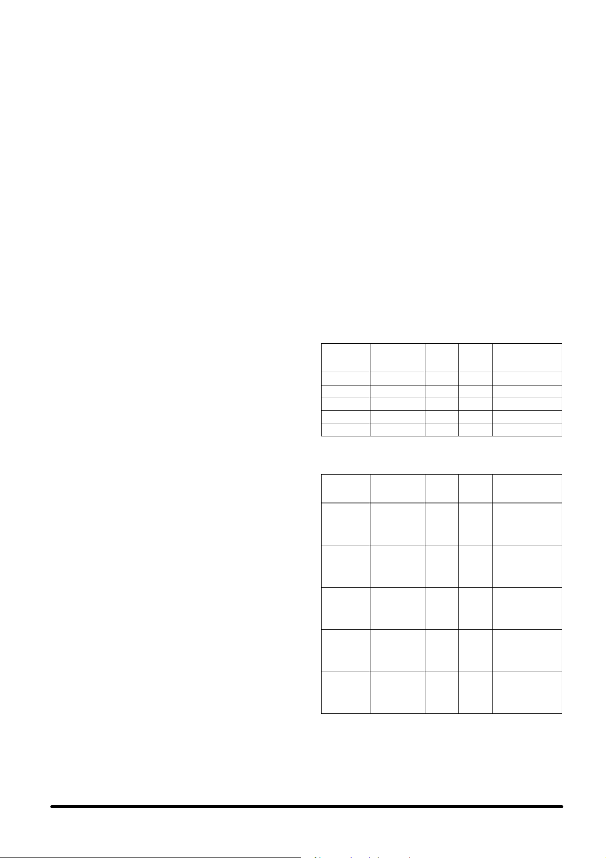
Tab. c --- Equivalent lengths (m) of: curves,
(mm
)
shut---off and non ---return valves
Nominal
diameter
(mm)
90° 45° 180° 90°
12 0.50 0.25 0.75 2.10 1.90
14 0.53 0.26 0.80 2.20 2.00
16 0.55 0.27 0.85 2.40 2.10
18 0.60 0.30 0.95 2.70 2.40
22 0.70 0.35 1.10 3.20 2.80
28 0.80 0.45 1.30 4.00 3.30
b) Evacuation of the refrigerant lines
The evacuation operation must be carried out with a special
(quality) vacuum pump, using the 1/4” SAE connectors, located on the unit on---off valves,
2.7 --- Condensate drain connection
During the cooling cycle part of the moisture in the air condenses on the evaporating coil. The condensate is collected
in the tank fitted under the coil and must be drained outside.
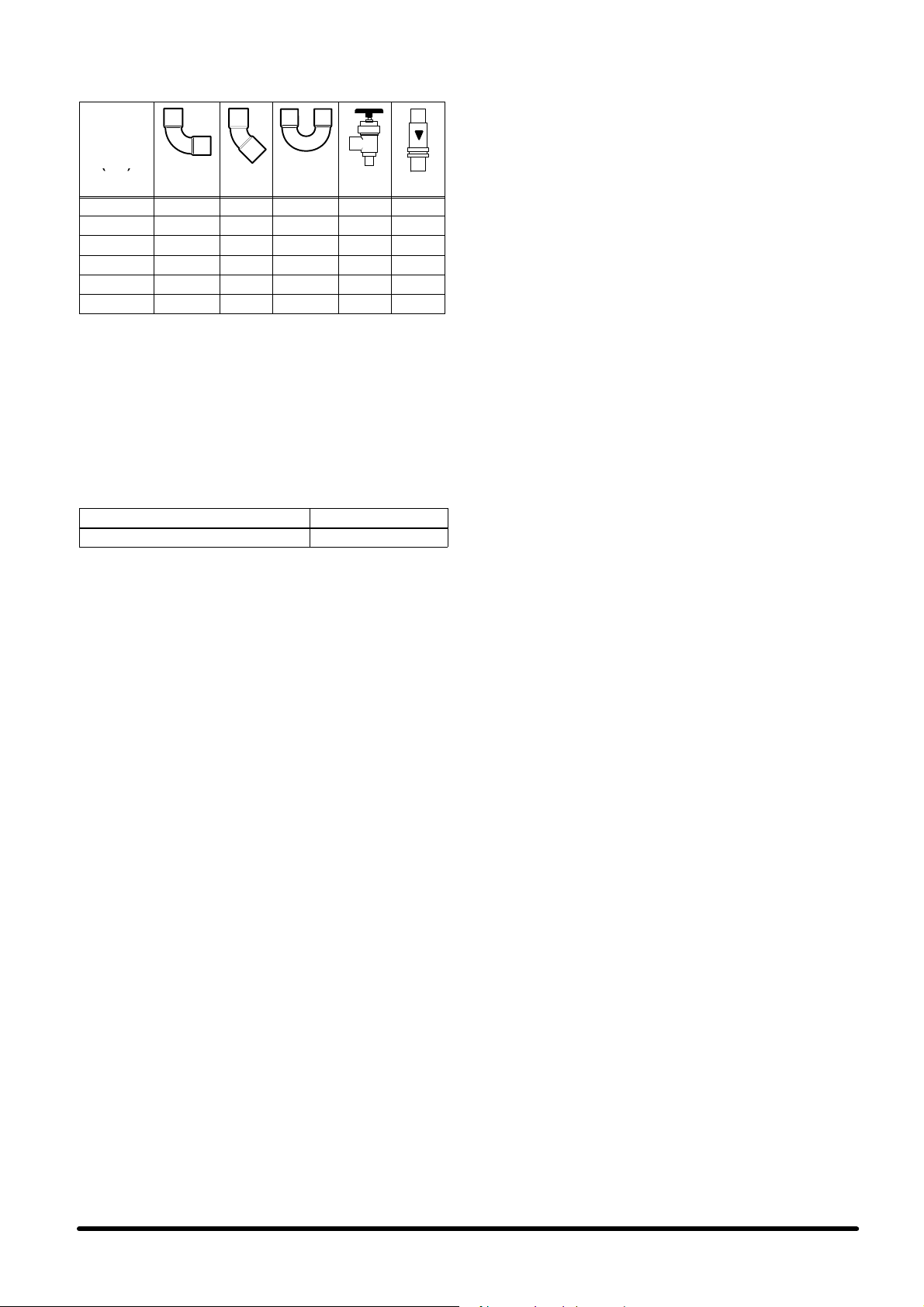
Tab. d --- Condensate drain connection
CONNECTOR DIMENSIONS
Condensate drain φ 21 mm
To drain the condensate:
S Use galvanized steel, PVC or flexible polythene pipe.
S CAUTION: DO NOT INTERCONNECT THE OUTLETS OF
DIFFERENT MACHINES.
S Make sure there is at least a 2% gradient towards the
drain outlet.
S There must beadraintrapplacedatleast30mmbelow
the drain tank.
S Fill the drain trap with water by pouring it into the conden-
sate tank.
2.8 --- Electrical connections and wiring
diagram (supplied with the unit)
For the electric connections of the indoor units HPSE and
outdoor units HPSC, refer to Fig. 5, Fig. 6 and Fig. 7.
Before connecting or disconnecting the fast couplers between the indoor unit and outdoor unit, make sure that the
main switch is in the “OFF” position and that:
S all electrical components are not damaged;
S allterminalscrewsaretight;
S thesupplyvoltageandfrequencyareasindicatedonthe
unit;
S there are no live components.
IMPORTANT:
The 48 Vdc supply (in the version ”Emergency Free Cooling”) must be delivered through a shielded cable, with the
connection of the shielding braid on the evaporating side.
The signal connection cable between the evaporating unit
and the condensing unit must be shielded, with the connection of the shielding braid on the evaporating side.
2.9 --- User interface
The standard control system on HPS is based on a microprocessor board mounted inside the electrical panel, which can
be connected to a user interface (remote display) that can be
positioned inside the room as required. The user interface
(remote display), when installed, is mounted in a painted
metal box and connected to the air conditioner using a
multi---pole screened cable (optional accessory).
2.10 --- Emergency cooling version
(EFC 48 VDC / 230 VAC)
When this option is used install the supply cable as described
in the electrical diagram.
In the 48VDC units respect the polarity “+” and “ --- ”.
2.11 --- Electrical protection
CAUTION: For the electrical protection of the conditioner an
adequate switch with current protection must be installed in
the power supply line. For the selection of the disconnect
switch please refer to Tab. 7.
3 --- Starting and stopping
3 . 1 --- F i r s t s t a r t --- u p
(or after a long halt)
Before starting the air conditioner check if the power supply
voltage and frequency comply with those on the identification plate of the unit. After this, it is possible to power the unit
by operating the main switch. For units equipped with PowerFace microprocessor control, it is possible to start and stop
the unit by following the instructions given below.
For units equipped with POWERFACE interface only:
S The unit is started by pressing the main switch ON.
S The unit is stopped by pressing the main switch OFF.
For units equipped with a local or remote display interface:
S The unit is started by pressing the switch with LED.
S The unit is stopped by pressing the switch with LED.
For units supplied with a HIROMATIC interface:
S Start by pressing the ON --- OFF push button on the Hiro-
matic (confirmed by SYS.ON on the display).
S Stop by pressing the ON --- OFF push button on the Hiro-
matic (confirmed by SYS.OFF. on the display).
IMPORTANT:
In both cases it is extremely important to consider the status
of the digital input to the PowerFace microprocessor control
managing the unit ON ---OFF (see relevant handbook and wiring diagram). Indeed, for the unit to start (operating on the
unit main switch, or on the ON --- OFF button of the HIROMATIC interface), the digital input must be bridged (see wiring
diagram). Check that there are no active alarms; wait until the
system reaches the standard operation and then make the
following checks:
S Check that the fans are working correctly.
S Make sure that the temperature is controlled and the
compressor and the heaters (optional) work when required.
S Make sure that the condensing unit fan speed controller
regulates the fan operation (only on “HPSCxxA/L” models).
3 . 2 --- S t a r t --- u p w i t h l o w o u t s i d e t e m p e r a -
ture (only on “HPSCxxA/L” models)
In case of low outside temperature (<0_C), the unit start---up
is helped by the delay time of the low pressure alarm, within
which the pressures in the refrigerating circuit reach the standard operation values.
3 . 3 --- S e l f t e s t
The self---test function is possible only when a unit has the remote or local display installed. The self --- test function, performs a sequential, automatic check of components such as
the compressor, fan, heaters, Freecooling damper, alarm
relay and warning relay. This eliminates the need for manual
control and leads to a remarkable decrease in the time
needed for starting the unit, with the ability to carry out a quick
check of the main components for the correct conditioner
operation.
pag. 3
Page 8
3.4 --- Starting and stopping
For the units provided with the POWERFACE control, you
can switch on/off using the main switch.
For the units provided with HIROMATIC interface:
S Start up the unit by pressing the Hiromatic ON --- OFF
push button (confirmed by SYS.ON on the display).
S Stop the unit by pressing the Hiromatic ON --- OFF push
button (confirmed by SYS.OFF on the display).
4 --- O p e r a t i o n
The unit operation is completely automatic. The sequence
below explains (with the assistance of Fig. 8 ---Operation
diagram) how the unit operates (see also Fig. 9 and Fig. 10
--- Refrigerating circuit):
1) The temperature sensor, positioned inside the HPSE
evaporating unit, informs the control about the condition
of the return air.
2) The control compares the information received with the
programmed Set Point value (= minimum indoor temperature) and Proportional Band (and Differential in the
versions with optional Freecooling), activating the conditioner’s air treatment modes as follows:
Cooling (Fig. 8a)
After switching the unit on, the evaporator fan starts immediately whereas the compressor is started only when the temperature of the room to be conditioned exceeds the set value.
In the HPSCxxA/L unit versions, the condensing unit fan
starts automatically if the condensing pressure increases
(control through Variex), while in the other versions the fan/s
is/are controlled by a pressure switch ensuring a limit lower
than the condensing pressure. The air taken in by the evaporator fan enters the unit through the side intakes, passing
through the filters, and then reaches the evaporator. The cold
refrigerant flows inside the evaporator pipes, thus cooling the
air passing through it. The treated air is conveyed into the
conditioned room through the supply outlet. The heat taken
from the room and that generated by the conditioner motor
operation is rejected through condensing coil located in the
external condensing unit and cooled with outside air by the
condenser fan. For the operation logic of the controls see
chapter 5.
Heating (optional)
Heating of the air is achieved by means of electric heaters,
located in the air flow and activated according to the logic set
on the controls (see chapter 5).
Freecooling (optional)
When the temperature of the outside air is sufficiently below
that of the inside air it is possible to use this difference to provide cooling inside the room by direct intake of the outside air,
i.e. without using the compressor. In this way it is possible to
achieve considerable energy savings. When the required
conditions occur, the servo --- motor, managed by the PowerFace control, opens the modulating damper which separates
the flow of the inside air and outside air. Outside air, drawn
into the room by the fan, is exhausted through an overpressure damper* which is installed on an outside wall of the
room and is protected by an external rainproof grille*. The
degree of opening of the damper is determined as a function
of the temperature set point and the return air temperature.
4.1 --- Control of the condenser fan speed
(“HPSCxxA/L” models only)
A sensor is positioned so as to detect the condensing pressure of the refrigeration gas. On the basis of this information,
an electronic device (Variex) modulates the fan speed in
order to keep the condensing pressure within the permitted
range. In this way, besides optimizing the compressor operation, you can have a reduction of the sound pressure level
(mainly during the night), easier start --- up of the compressor
at low temperatures and some energy saving.
For the calibration of the speed controller refer to chap. 6.
4 . 2 --- E m e r g e n c y c o o l i n g (optional)
4.2.1 --- Emergency cooling 48VDC
With the 48VDC emergency cooling option, the evaporator
fan, freecooling damper actuator and controls are always
supplied at 48VDC, while the compressor, the condenser fan
and the heaters are connected to the AC mains. If the AC
mains supply fails, the conditioner does not stop but continues to circulate the air, activating the Freecooling as soon
as the relevant conditions are reached, automatically optimized in the event of mains failure.
IMPORTANT:
For proper operation, the unit must always be fed by 48VDC.
4.2.2 --- Emergency cooling 230VAC --- 50Hz
In case of AC mains failure, the evaporator fan, freecooling
damper actuator and controls are supplied by a second
230V/1Ph/50Hz supply, arranged by the user (UPS/generator), ensuring operation in the same way as the 48VDC version.
CAUTION:
For safety reasons open the main switch.
5 --- Operating logic
The different unit versions feature different automatic operating logic, as described below.
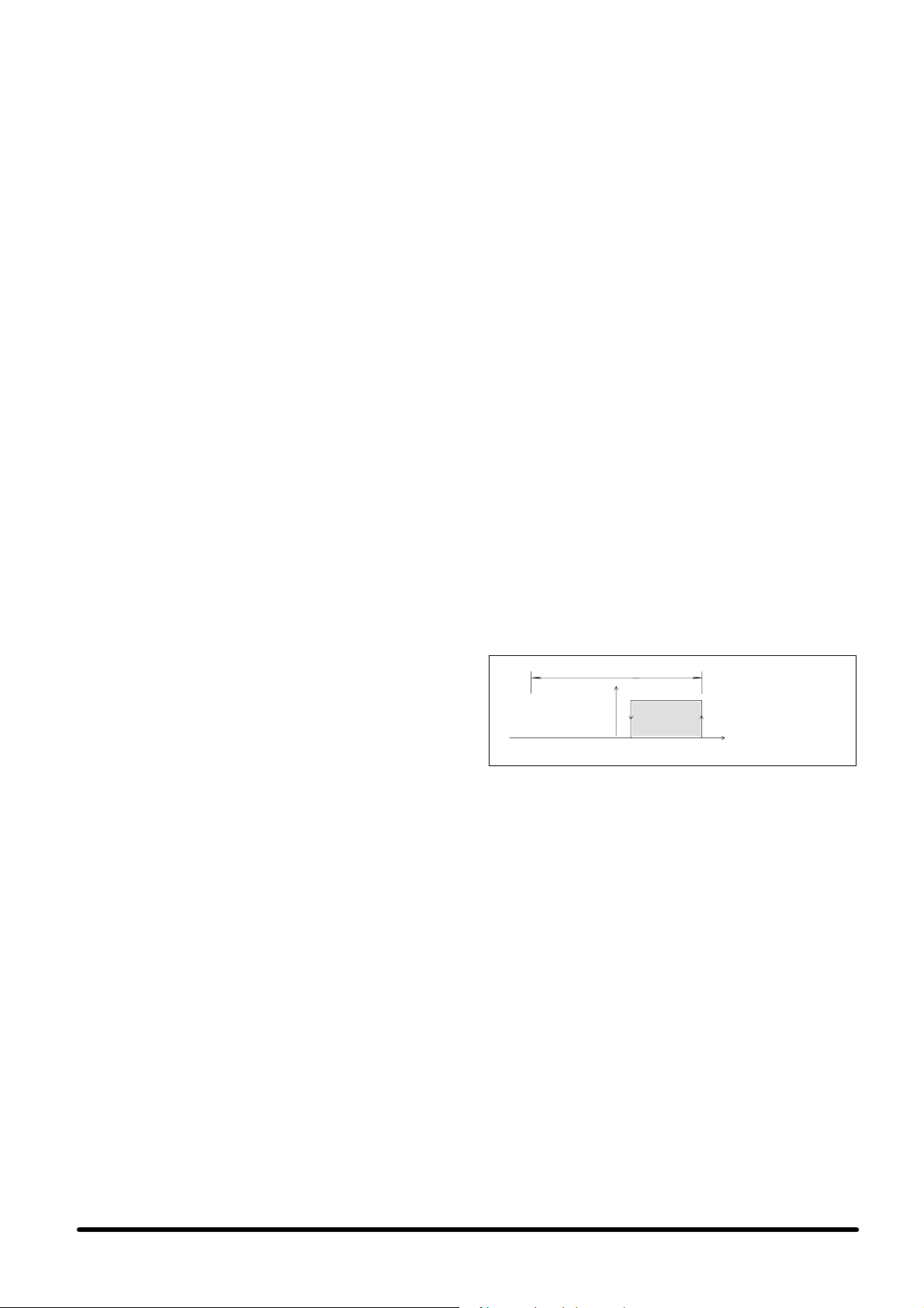
5.1 --- Cooling only unit
5.1.1 --- Control logic
The control algorithm is based on single --- step regulation for
the mechanical cooling, i.e. compressor start/stop. The control manages all the activation delays, ensuring correct operation and extending the operating life as much as possible.
Fig. a) Operation of the cooling only unit
PBand
Cooling only
unit
Set Cooling °C
5.2 --- Unit with electric heating
5.2.1 --- Control logic
For the heating and cooling version the control algorithm is
based on single---step regulation for the electric heating and
single step regulation for the compressor (mechanical cooling). The control manages all of the compressor activation
delays as previously described, ensuring its correct operation and maximising run times.
5.2.2 --- Dead band
In this version the “Dead band” parameter, in the “optional
devices” menu of the PowerFace microprocessor control is
very important, enabling the heating semi--- band to be
shirted by inserting a non --- sensitive area (ventilation only)
between the set point temperature and the start of the heating semi --- band (see Fig. b). In this way, without having to
alter the proportional band, the electric heating can be activated at lower temperatures (according to the value set for
the dead band) compared to the standard setting, consequently reducing the energy consumption of the heaters and
optimizing their operation according to the site requirements.
pag. 4
Page 9
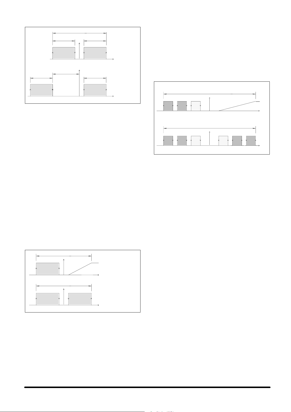
Fig. b) Unit operation with electrical heating
1
/2Band
1
/2Band
Dead Band
Set point CoolingHeating
PBand
Set point
1
/2Band
CoolingHeating °C
1
/2Band
Cooling and
heating unit
Cooling and
heating unit
with Dead band
°C
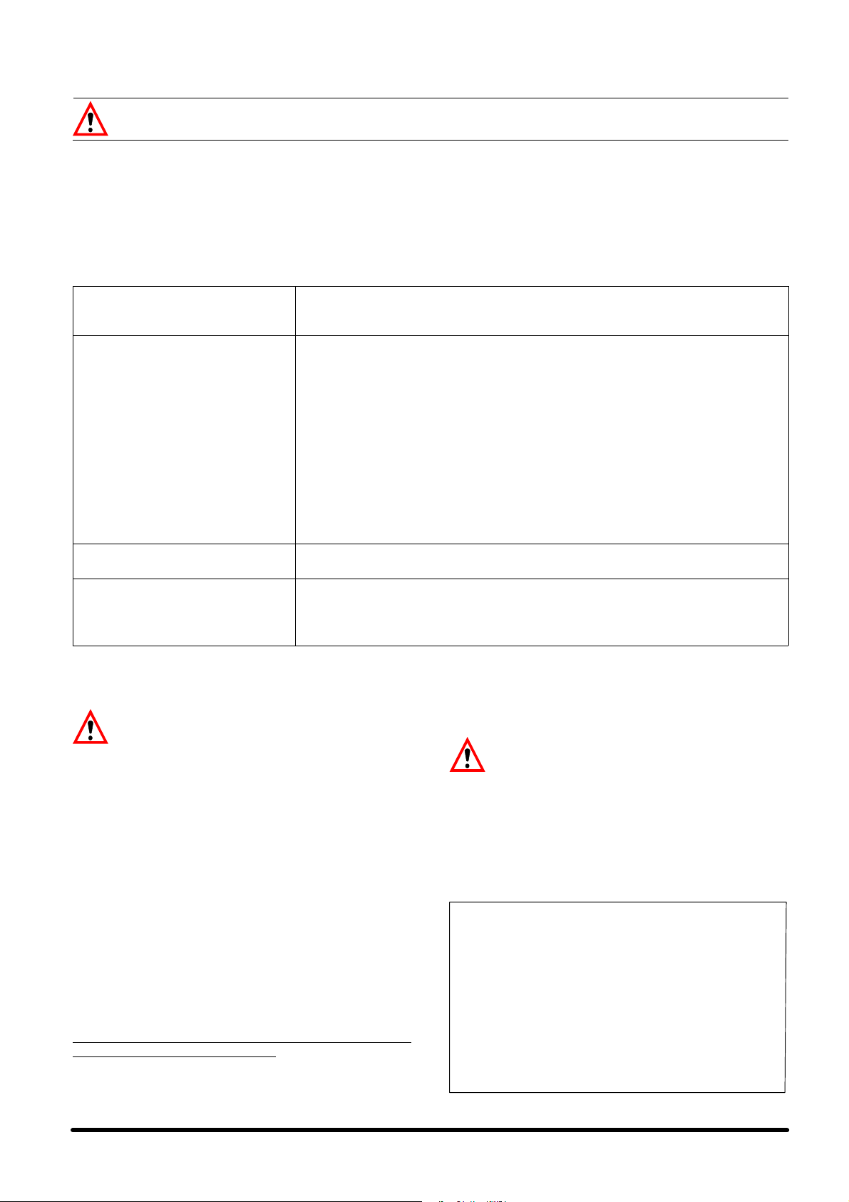
5.3 --- Unit with freecooling
5.3.1 --- Control logic
The control algorithm is based on single--- stage regulation
for the heating and mechanical cooling (compressor), with
modulating proportional --- integral control for the Freecooling
(see Fig. c). The control manages all of the compressor activation delays, as we have seen in the 2 previous cases, in
order to guarantee the proper operation and to extend its life.
The activation of the Freecooling mode occurs as a function
of the difference (that can be set) between the inside temperature and the outside temperature. This means that if the
difference between the two temperatures increases beyond
the set value, the unit automatically initiates the Freecooling
function; the compressor is deactivated and an analogue
output controls the 3 --- point servomotor of the damper. The
damper opening is determined as a function of the difference
between the outdoor and indoor temperatures and as a function of the intake air temperature, which cannot be lower than
a preset safety value. If the indoor temperature exceeds the
proportional band by more than 20% for over 10 minutes, the
unit reverts to compressor --- aided cooling and the Freecooling mode remains de --- activated for
1
/2hour. If the inside
temperature exceeds the proportional band by more than
50% for over 2 minutes, the Freecooling mode is de --- activated for 1 hour, and the unit reverts to cooling by means of
the refrigeration circuit.
Fig. c) Compressor, heater and damper opening
operation
PBand
Set CoolingHeating
PBand
Set CoolingHeating
Freecooling
mode
_C
Compressor
cooling mode
_C
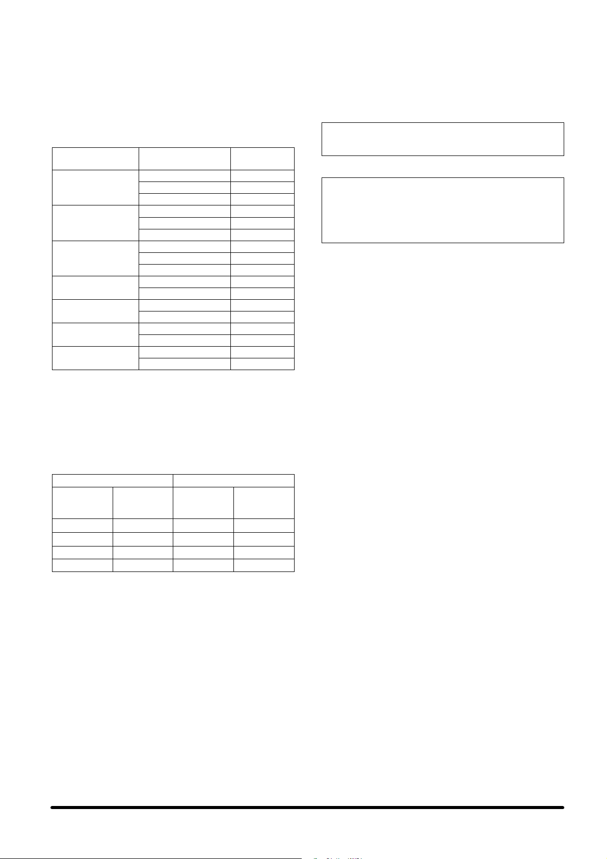
5.4 --- LAN local network management:
Stand---by and Cascade modes
The control of the units in stand ---by can be completely automatic, thanks to the possibility of connection with the PowerFace control. A unit in stand --- by is automatically activated in
case of an alarm causing the main unit to lock --- out. This also
occurs if the main unit is switched off or disappears from the
system due to a failure on the control connecting network
(bus). Rotation of the stand--- by units can be set to occur
automatically every 24 hours, so as to enable an even wear of
the system components. If the system is connected to a Hiromatic interface, it is possible to set timed daily or weekly rotation functions. When the Cascade function is activated, if sev-
eral units are simultaneously on, with the same Set Point, the
temperature used for the control is the average of those detected. In mechanical cooling mode, the proportional semi--band is divided by the number of units in the system, in order
to share the total available cooling capacity. The activation of
the Freecooling mode (if installed) is sequential on the different units forming the system, and precedes the possible activation of compressor for mechanical cooling.
Fig. d) shows an example, illustrating the operation of a system formed by three units.
Fig. d) System with 3 units in cascade ---
PowerFace control
Freecooling mode
PBand
3
3
1
2
Set _CCoolingHeating
Compressor cooling mode
PBand
11
223
Set _CCoolingHeating
5.5 --- Alarm control
Two sets of alarm contacts (each n.c. or n.o.) are available on
the terminal board of the electrical panel board for:
1) General Alarm (highest priority), including:
S Compressor alarm (high and low pressure).
S Sensor fault.
S Memory fault.
S Evaporator fan fault.
2) General Warning (lowest priority), including:
S High temperature.
S Low temperature.
A further General Warning is available in the unit equipped
with heating, signalling the following abnormal condition:
S Electrical heater fault.
NOTE:
S An alarm causes the unit to stop and the unit in stand --- by
(if available) to intervene.
S A warning does not stop the unit.
S Both the alarm and the warning activate visual and aud-
ible indication (on unit with Hiromatic).
S Both the alarm and the warning must be reset manually
on the PowerFace (or Hiromatic if installed).
Should the thermofuse intervene, the electrical heaters must
be replaced.
6 --- S e t t i n g s
S The air conditioner has already been factory --- tested and
set as described below (see Tab. 8).
S For the microprocessor control settings please refer to
the relevant manual (to avoid incorrect operation do not
use temperature and relative humidity set points or proportional bands which differ excessively from the standard settings).
pag. 5
Page 10
7 --- Maintenance / Spare parts
For safety reasons, always isolate the unit using the mains switch OFF, before opening the panels.
If installed:
AS THE MICROPROCESSOR CONTROL FEATURES AUTO-
MATIC RESTART (AFTER A SUPPLY INTERRUPTION), IT IS
RECOMMENDED THAT THIS FUNCTION IS DISABLED AND
THE MAINS SWITCH IS OPENED WHEN PERFORMING
ANY MAINTENANCE.
7.1 --- Routine maintenance
Maintenance program --- Monthly check
Check that the fan motor rotates freely without any abnormal noise, and ensure that the
FANS
AIR FILTERS
ELECTRICAL CIRCUIT
REFRIGERATION CIRCUIT
bearings are not running hot.
Also check the current absorption.
Check the conditions of the filters (3 for the recirculation air and 1 for the freecooling
air, if this option is included), if necessary, clean or replace them.
Toreplacethefiltersfortherecirculationair:
S Rotate the two filter ---locking fasteners securing each filter.
S Remove the filters.
S Fit the spare parts.
S Lock the filters by rotating the two fasteners in the opposite direction to secure each
filter.
To replace the filter for the freecooling air (if this option is included):
S Remove the unit lower panel.
S Remove the fastening bracket and pull the filter vertically downwards.
S Fit the spare part.
S Reposition the bracket and close the panel.
S Check the power supply on all phases.
S Ensure that all electrical connections are tight.
S Check the evaporating pressures (to be performed by a refrigeration technician).
S Check the compressor current absorption, the head pressure and the presence of
any unusual noise.
S Ensure that there is no ice formation on the evaporator.
S On a daily basis, check the control readings for tempera-
ture and, if shown, relative humidity.
S The Maintenance Programme described below should
be carried out by a skilled technician, preferably working
under a maintenance contract.
7.2 --- Extraordinary maintenance
CAUTION:
If you need to intervene immediately after the
unit stops, wait 5 minutes before accessing the
inner parts, as you could get burnt.
7.2.1 --- Check of the system vacuum and leaks
NOTE:
Before proceeding, recover all the refrigerant, according to
the local laws.
1) Switch the unit off (main switch on OFF).
2) Remove the panels necessary for inspecting the refriger-
ating circuit.
3) Connect a high efficiency vacuum pump to the needle
valves (Schräder) on the gas and liquid lines; also arrange a connection with a nitrogen bottle.
4) Load the circuit with nitrogen (7 bar/700 kPa). Find poss-
ible leaks in the circuit by soapy water or other specific
product (foaming agents), and repair as necessary.
5) Drain the circuit by a vacuum of 0.3 mbar absolute.
6) After 3 hours check not to have exceeded 1.3 mbar abso-
lute; this condition ensures a humidity lower than 50 ppm
inside the system. If the vacuum is not kept there are still
leaks; repeat the operations from point 4.
7.2.2 --- Refrigerant charging
After having eliminated the humidity from the refrigerating circuit (see 7.2.1), proceed as follows:
1) Make sure all the unit components are in operating order.
2) Using a charging hose, connect the cylinder to the liquid
line of the circuit. Drain the substances that cannot be
condensed from the hose.
Charge the circuit exclusively with the
refrigerant indicated on the identification
label.
Charge the quantity of refrigerant indicated in Tab. e.
3) Set the main switch on ON.
4) Start the compressor.
5) The charge operation can be considered finished when,
keeping the condensation temperature at a steady level
(~ 50_C, if necessary partially clog the condensing coil),
no more bubbles appear for at least ten minutes. Check
if the superheat in these conditions is 7---8 degrees.
Superheat calculation
a) With the unit operating in standard conditions,
measure the temperature of the suction line in the
point where the bulb of the thermal expansion valve
is fastened, in case of ”HPSCxxA/L” version unit, in the
compressor inlet, in case of other versions.
b) Detect the evaporation pressure gauge temperature
from a pressure gauge placed on the compressor
suction.
c) Subtract the obtained temperature value from the
one measured in point a).
The difference is the superheat value.
pag. 6
Page 11
7.2.3 --- R407C refrigerant units
Onl
l
ing/FC/EFC
Onl
l
i
FC/EF
C
HPSE1
0
HPSE1
0
HPSE1
2
HPSE1
4
7.2.3.1---Features of the refrigerating fluid R407C
At standard temperature and pressure it is a colourless gas
with low toxicity, non---flammable, and it has an allowed exposure limit value (AEL/TLV)corresponding to 1000 ppm (average value measured on 8 hours/day). In the event of leakage, air the room before use.
Tab. e --- R407C refrigerant charge
Internal
unit
HPSE 06
ycoo
HPSE 08
ycoo
ng
HPSE 08
HPSE 10
Only cooling
HPSE 10
FC / EFC
HPSE 12
Only cooling / FC / EFC
HPSE 14
Only cooling / FC / EFC
IMPORTANT:
The charges indicated in Tab. e refer to a 2 m length for the
gas and liquid pipes: Tab. f shows the indications for longer
measures on the additional charge in grams of refrigerant
R407C by each pipe meter of the gas and liquid lines, according to the diameters indicated in Tab. a.
External
unit
HPSC 060 2.2
HPSC 06A 2.7
HPSC 06L 3.7
HPSC 080 2.7
HPSC 08A 2.7
HPSC 08L 3.7
HPSC 080 3.0
HPSC 08A 3.0
HPSC 08L 4.0
HPSC 10A 2.7
HPSC 10L 3.7
HPSC 10A 3.0
HPSC 10L 4.0
HPSC 12A 3.6
HPSC 12L 4.6
HPSC 14A 3.6
HPSC 14L 4.6
R407C charge
(kg)
The oil to be used when topping up is EMKARATE RL
32--- 3MA or MOBIL EAL ARTIC 22CC, if it’s unavailable use
an oil with the same characteristics (see Tab. g and Tab. h).
NEVER M IX DIFFERENT OILS TOGETHER. CLEAN THE PIPING COMPLETELY BEFORE CHANGING THE TYPE OF OIL
USED.
Ta b . g --- E M K A R A T E RL 3 2 --- 3 M A o i l
viscosity at 40 _C
viscosity at 100 _C
viscosity index (ISO Grade)
:
31.2 cST
:
5.6 cST
:
32
Tab. h --- MOBIL EAL ARTIC 22CC oil
approx. specific weight (at 15_C)
flash point (C.O.C.)
pour point
viscosity index
viscosity at 40_C
viscosity at 100_C
:
0.99 kg/l
:
245 _C
:
< --- 5 4 _C
:
116
:
23.6 cST
:
4.7 cST
7.3 --- Dismantling the unit
The machine has been designed and built to ensure continuous operation.
The working life of some of the main components, such as
the fan and the compressor, depends on their maintenance.
If the unit has to be dismantled, this must be done by skilled
refrigerator technicians.
The refrigerating fluid and the lubricating oil in the circuit must
be disposed of in conformity with the laws in force in your
country.
7.4 --- Spare parts
We recommend the use of original spare parts.
When placing an order please refer to “Component List” enclosed with the machine and specify the unit model and serial
no.
Tab. f --- Additional charge in grams of refrigerant
R407C by meter of each line
Liquid line Gas line
Ø pipeline
(mm)
φ 12 x 1 85.0 φ 16 x 1 4.0
φ 16 x 1 160.0 φ 18 x 1 5.5
---
---
Add
charge
R407C g/m
--- φ 22 x 1 8.5
--- φ 28 x 1 14.5
Ø pipeline
(mm)
Add
charge
R407C g/m
pag. 7
Page 12

8 --- A p p e n d i x
8.1 --- Check the unit after the installation
The following list includes the checks to carry out to verify that HPS is intact after the installation.
IMPORTANT:
EVERY UNIT IS TESTED IN OUR PLANTS BEFORE DELIVERY.
A) STATIC CHECK
A.1) Evaporating unit HPSE
A.1.a) Sight check that the panels and rivets are in-
tact and well fixed.
A.1.b) Checkforthepresenceofacondensatedrain
for each machine and of the discharge pipe
supplied separately.
A.1.c) Check that the (optional) Freecooling air in-
take ducts (rigid or flexible) and the rainproof
external grille, with metallic prefilter (optional)
are available and fixed.
A.1.d) Check that the unit is fixed firmly to the ceiling
or to the wall, and that any fastening devices
passing along the walls of the room to be
conditioned are sealed.
A.1.e) Put the electrical board of the room in the
”OFF” position.
A.1.f) Check for the correct connection of the sup-
ply cables and of the Bus cable between the
PowerFacecardandtheremotedisplayor
between the PowerFace and Hiromatic (if installed, optional).
A.1.g) Check the fastening of cables, electronic
components and fuses.
A.1.h) Check the correct position of the air filter.
A.2) Motor ---condensing unit HPSC
A.2.a) Remove the panels of the compressor com-
partment to access the refrigerating circuit (if
the weather conditions allow this; prevent
water from entering the electric board and the
compressor compartment).
A.2.b) Check that the refrigerating circuit is intact
and that there are no oil stains in the compressor compartment and along the ducts.
A.2.c) Check the evaporating fan by turning it by
means of a screwdriver: it must be free to rotate without any abnormal noise.
A.2.d) Check that the electrical board is free from
foreign bodies, the correct connection to the
evaporating unit and that all electrical connections are tightened.
B) DYNAMIC CHECK
B.1) Check the ground connection.
B.2) Put the electrical board of the room in the
”ON” position.
B.3) Set the main switch of the indoor unit ”ON”.
B.4) Check the voltage at the main supply cables.
B.5) Check the voltage at the emergency supply
cables.
B.6) Only for the units equipped with Hiromatic re-
mote interface, set the wished system con-
figuration, such as set point, network (only for
”Advanced” versions, by assigning an
identification number for each unit), para-
meter sharing, stand --- by, freecooling differ-
entials (if installed), and so on.
B.7) Measure the current absorbed by the evapor-
ating fan only.
B.8) Start up the compressor (if necessary force
the system via the control) and wait until the
system is stable. Measure the absorbed cur-
rent,withbothfanandcompressoroperat-
ing.
B.9) Check all these values comparing them with
those shown in the machine plate.
B.10) Check the delivery temperature with a digital
thermometer.
B.11) Verify the superheating, according to par.
7.2.3.
B.12) Close the panels of the evaporating and mo-
tor---condensing units.
The unit is ready for the dynamic check.
pag. 8
Page 13
Tab. 1 -- 50 Hz Technical data for “COOLING ONLY” and “COOLING + HEATING” unit versions
(*)
(F and F + C) coupled with “HPSCxx0”
Model HPS 06 HPS 08
Operating limits
Main power supply voltage 230V ±10% / 1Ph / 50Hz 400V±10% / 3Ph+N+PE / 50Hz
Outdoor conditions
*
Indoor conditions with compressor running
Storage conditions
Sound pressure level
Outdoor sound pressure level
(1)
Indoor sound pressure level dB(A) 58.0 62.5
Standard electrical features
Compressor --- AC power input
Compressor --- AC operative current (OA)
(2)
(2)
Compressor --- AC max. current (FLA) A 11.4 5.1
Compressor --- AC starting current (LRA) A 47.0 32.0
Condenser fan --- AC power input
(2)
Condenser fan --- AC max. power input kW 0.08 0.10
Condenser fan --- AC operative current (OA)
(2)
Condenser fan --- AC max. current (FLA) A 1.4 1.4
Condenser fan --- AC starting current A 1.6 1.6
Evaporator fan --- AC power input
Evaporator fan --- AC operative current (OA)
Evaporator fan --- AC max. current (FLA)
(2)
(2)
(3)
Evaporator fan --- AC starting current A 1.3 2.7
Electric heating (optional)
Heating capacity kW 1.5 3.0
H e a t i n g --- m a x . cu r r e n t A 6.5
OA: Standard Operating Ampère
FLA: Full Load Ampère
LRA: Locked Rotor Ampère
Notes:
(*)
Maximum outdoor temperature referred to 30ûC / 35% R.H. indoor unit air suction (HPSE).
(**)
Conditions referred to the suction sections of the inner unit (HPSE); the min. indoor temperature is referred to 30% of indoor relative humidity and to the min.
outdoor temperature; for higher relative humidity and/or outdoor temperatures, the min. indoor temperature is higher than the table data.
(1)
Measured with 35ûC outdoor temperature at 2m far from the unit; free field conditions.
(2)
Indoor reference conditions: 30ûC / 35% R.H. at the HPSE indoor unit air suction sides; 35ûC outdoor. Nominal power supply.
(3)
It refers to nominal speed (Factory setting).
from: 10°C
to: 47°C 45°C
from: 24°C, 30% R.H. / 80% R.H.
(**)
to: 35°C, 40% R.H. 30°C, 40% R.H.
from: --- 4 0 °C, 5% R.H.
to: 55°C, 90% R.H.
dB(A) 50
kW 1.58 2.18
A 7.6 3.9
kW 0.08 0.10
A 0.6 0.7
kW 0.18 0.35
A 0.8 1.5
A 1.0 2.0
pag. 9
Page 14
Tab. 2 -- 50 Hz Technical data for “FREECOOLING” and “230V/1Ph/50Hz EMERGENCY FREECOOLING”
(**
)
unit versions (FC and EFC -- AC) coupled with “HPSCxx0”
Model HPS 06 HPS 08
Operating limits
Main power supply voltage 230V ±10% / 1Ph / 50Hz 400V±10% / 3Ph+N+PE / 50Hz
Emergency power supply voltage
Outdoor conditions
**
Indoor conditions with compressor running
Storage conditions
from: 10°C
to: 48°C 45°C
from: 24°C, 30% R.H. / 80% R.H.
to: 35°C, 40% R.H. 30°C, 40% R.H.
from: --- 4 0 °C, 5% R.H.
to: 55°C, 90% R.H.
Sound pressure level
Outdoor sound pressure level
(1)
dB(A) 50
Indoor sound pressure level dB(A) 59.0 62.5
Standard electrical features
Compressor --- AC power input
Compressor --- AC operative current (OA)
(2)
(2)
kW 1.57 2.18
A 7.3 3.9
Compressor --- AC max. current (FLA) A 11.4 5.1
Compressor --- AC starting current (LRA) A 47.0 32.0
Condenser fan --- AC power input
(2)
kW 0.08 0.10
Condenser fan --- AC max. power input kW 0.08 0.10
Condenser fan --- AC operative current (OA)
(2)
A 0.6 0.7
Condenser fan --- AC max. current (FLA) A 1.4 1.4
Condenser fan --- AC max. current (FLA) A 1.6 1.6
Evaporator fan --- AC power input
Evaporator fan --- AC operative current (OA)
Evaporator fan --- AC max. current (FLA)
(2)
(2)
(3)
kW 0.14 0.39
A 0.6 2.8
A 0.6 2.4
Evaporator fan --- AC starting current A 1.2 5.3
Electric heating (optional)
Heating capacity kW 1.5 3.0
H e a t i n g --- m a x . cu r r e n t A 6.5
OA: Standard Operating Ampère
FLA: Full Load Ampère
LRA: Locked Rotor Ampère
Notes:
(*)
The emergency cooling option (EFC) is required.
(**)
Maximum outdoor temperature referred to 30ûC / 35% R.H. indoor unit air suction (HPSE).
(***)
Conditions referred to the suction sections of the inner unit (HPSE); the min. indoor temperature is referred to 30% of indoor relative humidity and to the min.
outdoor temperature; for higher relative humidity and/or outdoor temperatures, the min. indoor temperature is higher than the table data.
(1)
Measured with 35ûC outdoor temperature at 2m far from the unit; free field conditions.
(2)
Indoor reference conditions: 30ûC / 35% R.H. at the HPSE indoor unit air suction sides; 35ûC outdoor. Nominal power supply.
(3)
It refers to nominal speed (Factory setting).
230V ±10% / 1Ph+PE / 50Hz
(with emergency cooling)
(*)
(***)
pag. 10
Page 15

Tab. 3 -- 50 Hz Technical data for “FREECOOLING” and “48Vdc EMERGENCY FREECOOLING” unit
(**
)
versions (FC and EFC--DC) coupled with “HPSCxx0”
Model HPS 06 HPS 08
Operating limits
Main power supply voltage 230V ±10% / 1Ph / 50Hz 400V±10% / 3Ph+N+PE / 50Hz
Emergency power supply voltage
Outdoor conditions
**
Indoor conditions with compressor running
Storage conditions
from: 10°C
to: 48°C 45°C
from: 24°C, 30% R.H.. / 80% R.H.
to: 35°C, 40% R.H. 30°C, 40% R.H.
from: --- 4 0 °C, 5% R.H.
to: 55°C, 90% R.H.
Sound pressure level
Outdoor sound pressure level
(1)
dB(A) 50
Indoor sound pressure level dB(A) 57 62
Standard electrical features
Compressor --- AC power input
Compressor --- AC operative current (OA)
(2)
(2)
kW 1.57 2.17
A 7.3 3.9
Compressor --- AC max. current (FLA) A 11.4 5.1
Compressor --- AC starting current (LRA) A 47.0 32.0
Condenser fan --- AC power input
(2)
kW 0.08 0.10
Condenser fan --- AC max. power input kW 0.08 0.10
Condenser fan --- AC operative current (OA)
(2)
A 0.6 0.7
Condenser fan --- AC max. current (FLA) A 1.4 1.4
Condenser fan --- AC max. current (FLA) A 1.6 1.6
Evaporator fan --- DC power input
Evaporator fan -- - DC operative current (OA)
Evaporator fan --- DC max. current (FLA)
(2)
(2)
(3)
kW 0.10 0.28
A 2.6 5.8
A 2.6 9.6
Evaporator fan --- DC starting current A 0.1 0.1
Electric heating (optional)
Heating capacity kW 1.5 3.0
H e a t i n g --- m a x . cu r r e n t A 6.5
OA: Standard Operating Ampère
FLA: Full Load Ampère
LRA: Locked Rotor Ampère
Notes:
(*)
The emergency cooling option (EFC) is required.
(**)
Maximum outdoor temperature referred to 30ûC / 35% R.H. indoor unit air suction (HPSE).
(***)
Conditions referred to the suction sections of the inner unit (HPSE); the min. indoor temperature is referred to 30% of indoor relative humidity and to the min.
outdoor temperature; for higher relative humidity and/or outdoor temperatures, the min. indoor temperature is higher than the table data.
(1)
Measured with 35ûC outdoor temperature at 2m far from the unit; free field conditions.
(2)
Indoor reference conditions: 30ûC / 35% R.H. at the HPSE indoor unit air suction sides; 35ûC outdoor. Nominal power supply.
(3)
It refers to nominal speed (Factory setting).
48VDC ±17%
(with emergency cooling)
(*)
(***)
pag. 11
Page 16

Tab. 4 -- 50 Hz Technical data for ”COOLING ONLY” and “COOLING + HEATING” unit versions
(*)
(F and F+C) coupled with “HPSCxxA/L”
Model HPS 06 HPS 08 HPS 10 HPS 12 HPS 14
Operating limits
Main power supply voltage
Outdoor conditions
*
Indoor conditions with compressor running
Storage conditions
Sound pressure level
Outdoor sound pressure level
(1)
dB(A) 48.5 48.5 52.5 53.5 55.0
Indoor sound pressure level dB(A) 58.0 62.5 62.5 64.0 64.0
Standard electrical features
Compressor --- AC power input
Compressor --- AC operative current (OA)
(2)
(2)
Compressor --- AC max. current (FLA) A 11.4 5.1 7.0 10.0 10.2
Compressor --- AC starting current (LRA) A 47.0 32.0 46.0 50.0 63.0
Condenser fan --- AC power input
(2)
Condenser fan --- AC max. power input kW 0.24 0.24 0.48 0.48 0.48
Condenser fan --- AC operative current (OA)
(2)
Condenser fan --- AC max. current (FLA) A 1.4 1.4 2.8 2.8 2.8
Condenser fan --- AC max. current (FLA) A 1.6 1.6 3.3 3.3 3.3
Evaporator fan --- AC power input
Evaporator fan --- AC operative current (OA)
Evaporator fan --- AC max. current (FLA)
(2)
(2)
(3)
Evaporator fan --- AC starting current A 1.3 2.7 2.7 2.7 2.7
Electric heating (optional)
Heating capacity kW 1.5 3.0 3.0 4.5 6.0
H e a t i n g --- m a x . cu r r e n t A 6.5 13.0
OA: Standard Operating Ampère
FLA: Full Load Ampère
LRA: Locked Rotor Ampère
Notes:
(*)
Maximum outdoor temperature referred to 30ûC / 35% R.H. indoor unit air suction (HPSE).
(**)
Conditions referred to the suction sections of the inner unit (HPSE); the min. indoor temperature is referred to 30% of indoor relative humidity and to the min.
outdoor temperature; for higher relative humidity and/or outdoor temperatures, the min. indoor temperature is higher than the table data.
(1)
Measured with 35ûC outdoor temperature at 2m far from the unit; free field conditions.
(2)
Indoor reference conditions: 30ûC / 35% R.H. at the HPSE indoor unit air suction sides; 35ûC outdoor. Nominal power supply.
(3)
It refers to nominal speed (Factory setting).
230V ±10%
/1Ph/50Hz
400V ±10% / 3Ph+N+PE / 50Hz
from: --- 3 0 °C
to: 51°C 50°C
from: 24°C, 30% R.H / 80% R.H.
to:
34°C,
40% R.H.
30°C, 40% R.H.
(**)
from: --- 4 0 °C, 5% R.H.
to: 55°C, 90% R.H.
kW 1.73 2.23 3.06 3.75 4.68
A 8.0 4.0 5.5 6.6 8.6
kW 0.07 0.10 0.22 0.22 0.28
A 0.6 0.7 1.5 1.5 1.7
kW 0.18 0.35 0.35 0.34 0.34
A 0.8 1.5 1.5 2.0 2.0
A 1.0 2.0 2.0 2.0 2.0
pag. 12
Page 17

Tab. 5 -- 50 Hz Technical data for “FREECOOLING” and “230V/1Ph/50Hz EMERGENCY FREECOOLING”
(**
)
unit versions (FC and EFC -- AC) coupled with “HPSCxxA/L”
Model HPS 06 HPS 08 HPS 10 HPS 12 HPS 14
Operating limits
Main power supply voltage
Emergency power supply voltage
Outdoor conditions
**
Indoor conditions with compressor running
Storage conditions
Sound pressure level
Outdoor sound pressure level
(1)
dB(A) 48.5 48.5 52.5 53.5 55.0
Indoor sound pressure level dB(A) 59.0 62.5 62.5 64.5 66.0
Standard electrical features
Compressor --- AC power input
Compressor --- AC operative current (OA)
(2)
(2)
Compressor --- AC max. current (FLA) A 11.4 5.1 7.0 10.0 10.2
Compressor --- AC starting current (LRA) A 47.0 32.0 46.0 50.0 63.0
Condenser fan --- AC power input
(2)
Condenser fan --- AC max. power input kW 0.24 0.24 0.48 0.48 0.48
Condenser fan --- AC operative current (OA)
(2)
Condenser fan --- AC max. current (FLA) A 1.4 1.4 2.8 2.8 2.8
Condenser fan --- AC max. current (FLA) A 1.6 1.6 3.3 3.3 3.3
Evaporator fan --- AC power input
Evaporator fan --- AC operative current (OA)
Evaporator fan --- AC max. current (FLA)
(2)
(2)
(3)
Evaporator fan --- AC starting current A 1.2 5.3 5.3 5.3 5.3
Electric heating (optional)
Heating capacity kW 1.5 3.0 3.0 4.5 6.0
H e a t i n g --- m a x . cu r r e n t A 6.5 13.0
OA: Standard Operating Ampère
FLA: Full Load Ampère
LRA: Locked Rotor Ampère
Notes:
(*)
The emergency cooling option (EFC) is required.
(**)
Maximum outdoor temperature referred to 30ûC / 35% R.H. indoor unit air suction (HPSE).
(***)
Conditions referred to the suction sections of the inner unit (HPSE); the min. indoor temperature is referred to 30% of indoor relative humidity and to the min.
outdoor temperature; for higher relative humidity and/or outdoor temperatures, the min. indoor temperature is higher than the table data.
(1)
Measured with 35ûC outdoor temperature at 2m far from the unit; free field conditions.
(2)
Indoor reference conditions: 30ûC / 35% R.H. at the HPSE indoor unit air suction sides; 35ûC outdoor. Nominal power supply.
(3)
It refers to nominal speed (Factory setting).
230V ±10%
/1Ph/50Hz
400V ±10% / 3Ph+N+PE / 50Hz
230V ±10% / 1Ph+PE / 50Hz
(with emergency cooling)
(*)
from: --- 3 0 °C
to: 52°C 50°C
from: 24°C, 30% R.H / 80% R.H.
to:
35°C,
40% R.H.
30°C, 40% R.H
(***)
from: --- 4 0 °C, 5% R.H.
to: 55°C, 90% R.H.
kW 1.74 2.22 3.06 3.75 4.66
A 8.1 4.0 5.5 6.6 8.5
kW 0.07 0.10 0.22 0.22 0.28
A 0.6 0.7 1.5 1.5 1.7
kW 0.14 0.39 0.39 0.45 0.48
A 0.6 2.8 2.8 2.9 2.4
A 0.7 2.4 2.4 2.4 2.4
pag. 13
Page 18

Tab. 6 -- 50Hz T echnical data for “FREECOOLING” and “48Vdc EMERGENCY FREECOOLING” unit
(**
)
versions (FC and EFC--DC) coupled with “HPSCxxA/L”
Model HPS 06 HPS 08 HPS 10 HPS 12 HPS 14
Operating limits
Main power supply voltage
Emergency power supply voltage
Outdoor conditions
**
Indoor conditions with compressor running
Storage conditions
Sound pressure level
Outdoor sound pressure level
(1)
dB(A) 48.5 48.5 52.5 53.5 55.0
Indoor sound pressure level dB(A) 57.0 62.0 62.0 67.0 68.5
Standard electrical features
Compressor --- AC power input
Compressor --- AC operative current (OA)
(2)
(2)
Compressor --- AC max. current (FLA) A 11.4 5.1 7.0 10.0 10.2
Compressor --- AC starting current (LRA) A 47.0 32.0 46.0 50.0 63.0
Condenser fan --- AC power input
(2)
Condenser fan --- AC max. power input kW 0.24 0.24 0.48 0.48 0.48
Condenser fan --- AC operative current (OA)
(2)
Condenser fan --- AC max. current (FLA) A 1.4 1.4 2.8 2.8 2.8
Condenser fan --- AC max. current (FLA) A 1.6 1.6 3.3 3.3 3.3
Evaporator fan --- DC power input
Evaporator fan -- - DC operative current (OA)
Evaporator fan --- DC max. current (FLA)
(2)
(2)
(3)
Evaporator fan --- DC starting current A 0.1 0.1 0.1 0.1 0.1
Electric heating (optional)
Heating capacity kW 1.5 3.0 3.0 4.5 6.0
H e a t i n g --- m a x . cu r r e n t A 6.5 13.0
OA: Standard Operating Ampère
FLA: Full Load Ampère
LRA: Locked Rotor Ampère
Notes:
(*)
The emergency cooling option (EFC) is required.
(**)
Maximum outdoor temperature referred to 30ûC / 35% R.H. indoor unit air suction (HPSE).
(***)
Conditions referred to the suction sections of the inner unit (HPSE); the min. indoor temperature is referred to 30% of indoor relative humidity and to the min.
outdoor temperature; for higher relative humidity and/or outdoor temperatures, the min. indoor temperature is higher than the table data.
(1)
Measured with 35ûC outdoor temperature at 2m far from the unit; free field conditions.
(2)
Indoor reference conditions: 30ûC / 35% R.H. at the HPSE indoor unit air suction sides; 35ûC outdoor. Nominal power supply.
(3)
It refers to nominal speed (Factory setting).
230V ±10%
/1Ph/50Hz
400V ±10% / 3Ph+N+PE / 50Hz
48VDC ±17%
(with emergency cooling)
(*)
from: --- 3 0 °C
to: 52°C 50°C
from: 24°C, 30% R.H. / 80% R.H.
to:
35°C,
40% R.H.
30°C, 40% R.H.
(***)
from: --- 4 0 °C, 5% R.H.
to: 55°C, 90% R.H.
kW 1.74 2.23 3.06 3.75 4.66
A 8.1 4.0 5.5 6.6 8.5
kW 0.07 0.10 0.22 0.22 0.28
A 0.6 0.7 1.5 1.5 1.7
kW 0.10 0.28 0.28 0.39 0.45
A 2.6 5.8 5.8 8.1 9.5
A 2.6 9.6 9.6 9.6 9.6
pag. 14
Page 19

Tab. 7 -- Differential current protection switch
“
HPS08
A
HPS10
20A
2
HPS12
(Ccurve
)
g
Cablesizing
V
/
HPS08
A
HPS10
20A
4x2.5mm
+
2x2.5mm
+
HPS12
(Ccue)Tx2.5mmTx2.5m
m
48VDC
HPS08
A4x
HPS10
20A
4x2.5mm2+
2x2.5mm2+
HPS12
(Ccurve)Tx2.5mmTx
2.5mm
50Hz unit versions (”cooling only”,
“
cooling+heating” and“freecooling”)
”
“
”
Unit power supply 230V / 1Ph / 50Hz 400V / 3Ph / 50Hz + N
HPS 06
Differential current protection switch
I nn = 0.03A
2poles 4poles
20A
(”C” curve)
--- 2 x 2.5mm2+Tx2.5mm
Cable sizing
2
HPS 10
HPS 12
---
HPS 14
Emergency freecooling” unit version
230V/1Ph/50Hz
”
Main line power supply
Unit EFC ---AC line power supply
HPS 06
HPS 10
HPS 12
Differential current protection switch
I nn = 0.03A
2poles 4poles
230
main line
20A
(”C” curve)
1Ph/50Hz
E F C --- A C
line
10A
(”C” curve)
400V / 3Ph / 50Hz + N
230V / 1Ph / 50Hz + N
main line
---
HPS 14
“Emergency freecooling” unit version
48VDC
Differential current protection switch I nn = 0.03A
2poles 4poles
Main line power supply 230V / 1Ph / 50Hz 400V / 3Ph / 50Hz + N
Unit EFC ---DC line power supply 48VDC
main line
E F C --- D C
line
main line
20
(”C” curve)
4x2.5mm2+Tx2.5mm
Cable sizin
E F C --- A C
line
main line
--- 2 x 2.5mm2+Tx2.5mm
20
(”C” curve)
4x2.5mm2+ 2x2.5mm2+
T x 2.5mm
2
Cable sizing
E F C --- D C
line
main line
E F C --- A C
line
2
T x 2.5mm
E F C --- D C
line
2
HPS 06
HPS 10
HPS 12
20A
(”C” curve)6A(”C” curve)
---
--- 2 x 2.5mm2+Tx2.5mm
20
(”C” curve)
2.5mm2+ 2x2.5mm2+
T x 2.5mm
2
HPS 14
Notes:
S
The cables have to be sized in compliance with local standards and according to the type and characteristics (e.g. Amperes) of installation.
S
The specific power of the user --- installed switch, must be lower than 300.000 (A2xs).
S
Prescriptions on the differential relay required to the user:
S
for special places (healthcare facilities, etc.) comply with the local regulations;
S
For ordinary places, a low sensitivity is suggested (30 mA) coordinated with the value of the ground heater (IEC 364): Ra≤50/la(Art. 413.1.4.1, CEI 64 --- 8);
S
In case of frequent over---voltages with mains impulse, it is advisable to install a selective differential and to evaluate the need for adopting other devices.
T x 2.5mm
2
2
pag. 15
Page 20

Tab. 8 -- Settings
Component Setting Notes
Low pressure switch (LP)
High pressure switch (HP)
Fan speed controller (BV)
(only for “HPSCxxA/L” configuration unit)
STOP: 1.0 bar
START: 2.0 bar
(fixed settings)
STOP: 28.0 bar
START: 20.0 bar
(fixed settings)
SET: 25.0 bar
(for the adjustment refer to the instruc-
BANDA P: 3.8 bar
tions supplied with the machine)
Automatic reset
Manual reset pressing
the push button
Tab. 9 -- Fire proof classification of electrical/electronic components
(according to UL 94 normative --- vertical burning)
Electrical/electronic components Fire proof classification
Contactors V1
Automatic switches V1
Cables V1
PC Board (PowerFace) V0
HP and LP pressure switches V1
Clogged filter V2
Terminal block for internal unit (HPSE) V0
Terminal block for external unit (HPSC) V1
Ducts V1
Soft--- Starter V1
Connectors V0
Auxiliary relais V1
Electrical heater safety thermostat V1
Sensors V1
Servomotor V1
pag. 16
Page 21

28.528.5 803
Refrigerant
connection
LEFT SIDE VIEW
803
310
FRONT VIEW (CIRCULAR DUCTS VERSION)
251,5 300 251,5
N. 2 collars
ø200 H=35 mm
155155
310
Electrical
connection
Refrigerant
connection
803 28,528,5
FRONTVIEW(RECTANGULARDUCTVERSION)
120,5 562 120,5
Collar
190x560 H=35 mm
59 192 59
310
unit fixing
N. 8 slots 9x12 ---
70994
RIGHT SIDE VIEW
Condensate drain
TOP VIEW
150 150 125
803
228 150
Fig. 1a --- Evaporating unit HPSE 06 (version with freecooling)
14.5
13,583313,5
860
Fig. 1 --- Overall dimensions
pag. 17
Page 22

28.528.5 903
Refrigerant
connection
LEFT SIDE VIEW
903
375
Electrical
connection
903 28,528,5
276,5 350 276,5
150,7 601,6 150,7
187,5
375
187,5
FRONT VIEW (CIRCULAR DUCTS VERSION)
FRONTVIEW(RECTANGULARDUCTVERSION)
N. 2 collars
ø250 H=35 mm
Refrigerant
connection
Collar
250x600 H=35 mm
61,7 251,6 61,7
375
226,5
unit fixing
N. 8 slots 9x12 ---
81588
RIGHT SIDE VIEW
F i g . 1 b --- E v a p o r a t i n g u n i t H P S E 0 8 --- 1 0 --- 1 2 --- 1 4 (version with freecooling)
Condensate drain
14.5
903
TOP VIEW
150 150
226,5 150
13,593313,5
960
pag. 18
Page 23

Electrical
connection
LEFT SIDE VIEW
FRONT VIEW
803
310
Refrigerant
connection
803
BOTTOM VIEW
860
310
28,5 803 28,5
unit fixing
N. 8 slots 9x12 ---
70994
803
RIGHT SIDE VIEW
F i g . 1 c --- E v a p o r a t i n g u n i t H P S E 0 6 --- 0 8 --- 1 0 (version without freecooling)
Condensate drain
14.5
TOP VIEW
228 150 150 150 125
13,583313,5
pag. 19
Page 24

Electrical
connection
LEFT SIDE VIEW
FRONT VIEW
903
375
Refrigerant
connection
903
BOTTOM VIEW
960
375
28,5 903 28,5
unit fixing
N. 8 slots 9x12 ---
80994
RIGHT SIDE VIEW
Condensate drain
903
TOP VIEW
226.5 150 150 150 226.5
F i g . 1 d --- E v a p o r a t i n g u n i t H P S E 1 2 --- 1 4 (version without freecooling)
14.5
13,593313,5
pag. 20
Page 25

A
FRONT VIEW
A --- A Se c .
132 656 132
A
80535
outlet
Refrigerant
338
SIDE VIEW
inlet
Refrigerant
Electrical
connections
390
1818
354
390
840
REAR VIEW
Fig. 1e --- Conde nsing unit HPSC 06--- 08
outlet
Refrigerant
920
inlet
Refrigerant
pag. 21
Page 26

A
27
656
FRONT VIEW
27
A --- A Se c .
132 132
A
115535
outlet
Refrigerant
338
SIDE VIEW
1190
inlet
Refrigerant
Electrical
connections
390
354 1818
390
REAR VIEW
920
F i g . 1 f --- C o n d e n s i n g u n i t H P S C 1 0 --- 1 2 --- 1 4
outlet
Refrigerant
pag. 22
inlet
Refrigerant
Page 27

F i g . 2 --- I n s t a l l a t i o n
F i g . 2 a --- E v a p o r a t i n g u n i t c e i l i n g i n s t a l l a t i o n H P S E 0 6 --- 0 8 --- 1 0 --- 1 2 --- 1 4
(version without freecooling)
375 (HPSE 12--14)
310 (HPSE 06--08--10)
Service area
for electical
min. 300
board
803 (HPSE 06--08--10)
903 (HPSE 12--14)
min. 200
pag. 23
Page 28

F i g . 2 b --- E v a p o r a t i n g u n i t i n s t a l l a t i o n H P S E 0 6 --- 0 8 --- 1 0 --- 1 2 --- 1 4
(version with freecooling)
C
Service area
for electical
Service area
for Freecooling
min. 300
A
filter
board
B
min. 200
HPSE A B C
06 min. 300 803 310
0 8 --- 1 0 --- 1 2 --- 1 4 min. 320 903 375
3
5
1
4
2
3
3
ITEM DESCRIPTION
1 Electrical box accessibility
2 Support for filter
3 Air filter
4 Freecooling filter accessibility
5 Electrical box
pag. 24
Page 29

F i g . 2 c --- E v a p o r a t i n g u n i t c e i l i n g i n s t a l l a t i o n H P S E 0 6 --- 0 8 --- 1 0 --- 1 2 --- 1 4
(version with freecooling)
4
1
10
11
9
23
8
7
6
5
5
ITEM DESCRIPTION
CODE
HPSE 06
CODE
H P S E 0 8 --- 1 0 --- 1 2 --- 1 4
1 Wall plate for circular ducts 13503801 13536101
2 2 flexible ducts with fixing clamps, L = 0.5 m 270190 (Ø 202mm) 270191 (Ø 254mm)
3 Fixing clamps --- ---
4 Wall plate for rectangular duct 13501801 13536001
5 Circular / rectangular version --- ---
6 Wall hole 400 x 200mm 600 x 400mm
7 Overpressure damper 134948 134992
8 Grille for overpressure damper 270206 117832
9 Aluminium grille with metallic prefilter 270202 270219
10 Metallic prefilter (included in item 9) --- ---
11 Wall hole 550 x 210mm 590 x 230mm
pag. 25
Page 30

Fig. 2d --- Condensing unit wall installation
1
2
3
4
5
3
2
1
HPSC 06 ---08
COD. 129201
H P S C 1 0 --- 1 2 --- 1 4
ITEM
1 Nut
2 Serrated lock washer
3 Washer
4 A n t i --- v i b r a t i n g m o u n t
5 Bracket
KIT DESCRIPTION
COD. 129201
pag. 26
Page 31

Fig. 3 --- Condenser positions
pag. 27
Page 32

F i g . 4 --- S e r v i c e a r e a H P S C 0 6 --- 0 8 --- 1 0 --- 1 2 --- 1 4
1
2
WALL IN FRONT
OF UNITS
WALL IN FRONT
OF UNITS
3
WALL BEHIND
UNITS
5
4
WALL BEHIND
UNITS
If H1 < 0.5 x H2 ⇒ L min. = 500 mm.........
If 0.5 x H2 ≤ H1 ≤ H2 ⇒ L min. = 800 mm...
5
If H1 > H2 ⇒ Not allowable configuration..............
pag. 28
M U L T I --- R O W S
INSTALLATION
Page 33

Fig. 5 --- Electric connections
AC
DC
(optional)
AC power supply
DC power supply (optional)
SC unit control
Powerface display
HPSE
No. 2 cable clips PG21
Remote
display
HPSC
AC line input
HPSC
HPSE
EFC line input
(48Vdc / 230Vac)
(Connectivity control option)
AC line input
Remote
display plug
(Standard control)
Hiromatic plug
No. 2 cable clips PG21
Free
No. 2 holes for cable clips PG21
(option EFC 48Vdc / 230Vac)
(Connectivity control option)
LAN plug
pag. 29
AC line output for
HPSC condensing unit
power supply
Auxiliary input
Page 34

48 Vdc
230 Vac / 50 Hz or
Emergency power supply
230 Vac / 50 Hz
Terminal Powerface terminal
optional
Fig. 6a --- HPSE + HPSC 06
(version with freecooling and EFC 230 Vac or EFC 48 Vdc)
HPSC 06 HPSE 06
2
+ ground
2
2x2.5mm
HP LP
Faston 6.3
5x1.5mm
Fig. 6 --- Electric connections between indoor unit HPSE and outdoor unit HPSC
pag. 30
Page 35

48 Vdc
230 Vac / 50 Hz or
Emergency power supply
400 V / N / 50 Hz
optional
(version with freecooling and EFC 230 Vac or EFC 48 Vdc)
Terminal Powerface terminal
2
+ ground
2
4x2.5mm
HP LP
5x1.5mm
H P S C 0 8 --- 1 0 --- 1 2 --- 1 4 H P S E 0 8 --- 1 0 --- 1 2 --- 1 4
F i g . 6 b --- H P S E + H P S C 0 8 --- 1 0 --- 1 2 --- 1 4
pag. 31
Page 36

Remote box
Alarm board
Supplied with the alarm board only
Remotable LCD display
RL 1
2
(24, 0, 70)
RL 2
COM 1/2
RL 3
COM 3
RL 4
RL 5
COM 4/5
Cable Hirobus 8 poles, screened
3x1.5mm
To Powerface To display
Y1 on Powerface board
Alarm board
(version without freecooling or in version EFC 230 Vac)
ALIM A
ING A
ALIM B
GND A
GND B
ING B
G N D ( --- )
G24 (+)
Electric board
F i g . 7 a --- H P S E 0 6 --- 0 8 --- 1 0 --- 1 2 --- 1 4
70
Fig. 7 --- Connections of the display and of the alarm board HPSE (optional)
pag. 32
Page 37

Remote box
Supplied with the alarm board only
Alarm board
70
Remotable LCD display
CN10
11
12
13910
14
17
181915
Cable Hirobus 8 poles, screened
2
(G, G0, 70)
16
Board TM 48
--- A 2
8
27034567
Faston 6.3
3x1.5mm
Faston 6.3
To Powerface To display
Y1 on Powerface board
70
Alarm board
G0
G
F u s e 1 A --- F
(version without freecooling or in version EFC 48 Vdc)
Electric board
CN 2CN 4
G
F i g . 7 b --- H P S E 0 6 --- 0 8 --- 1 0 --- 1 2 --- 1 4
pag. 33
G0
Page 38

Fig. 8 --- Operating diagram
Fig. 8a --- Operating diagram (without freecooling)
1
Return
air
CROSS
SECTION
2
Return air
Treated ai r
ITEM DESCRIPTION
1 Evaporating coil
2 Fan
TOP VIEW
(WITHOUT PANEL)
Return
air
CROSS
SECTION
Fig. 8b --- Operating diagram (with freecooling)
12 3 45
Freecooling
air
ITEM DESCRIPTION
1 Fresh air filter
2 Evaporating coil
3 Fan
4 Fan nozzle
5 Freecooling damper
Freecooling air
Return air
Treated ai r
TOP VIEW
(WITHOUT PANEL)
pag. 34
Page 39

F i g . 9 --- H P S 0 6 --- 0 8 ( H P S C x x 0 ) --- R e f r i g e r a t i n g d i a g r a m
Internal
unit
10
6
55
Connection pipe
12
11
LP
6
12
9
Supplying
limit
MC
HP
3
2
1
6
44
External
unit
7
13
ITEM DESCRIPTION
1 Compressor
2 Crankcase heater
3 High pressure switch (HP)
4 Air cooled condenser
5 Weld joint
6 Access valve
7 Filter dryer
8 ---
9 Expansion capillary
10 Evaporator
11 Low pressure switch (LP)
12 Shut---off valve
13 On --- Off fan pressure switch
pag. 35
Page 40

F i g . 1 0 --- H P S 0 6 --- 0 8 --- 1 0 --- 1 2 --- 1 4 ( H P S C x x A / L ) --- R e f r i g e r a t i n g d i a g r a m
7
11
Connection pipe
13
12
LP
6
MC
2
HP
3
1
6
Internal
unit
16
15
6
55
Supplying
limit
13
10
17
FG
9
8
44
External
unit
ITEM DESCRIPTION
1 Compressor
2 Crankcase heater
3 High pressure switch (HP)
4 Air cooled condenser
5 Weld joint
6 Access valve
7 Evaporator fan
8 Filter dryer
9 Sight glass (FG)
10 Thermostatic expa nsion valve
11 Evaporator
12 Low pressure switch (LP)
13 Shut---off valve
14 Fan pressure switch control
15 Liquid receiver (Opt.--- ”L” Digit)
16 Safety valve (Opt.--- ”L” Digit)
17 Shut -- -off solenoid valve (Opt.--- ”L” Digit)
HPC
14
pag. 36
Page 41

Fig. 11 --- Suggested refrigerant connections (HPSCxx0/A + HPSE)
Gas pipeline (Sloping 1%)
HPSC
(External Unit)
HPSC
(External Unit)
Liquid pipeline
10 m max. horizontal equivalent length
Gas pipeline
(Sloping 1%)
Gas pipeline
(Sloping 1%)
two syphons
distance between
1.5 m max. vertical
Liquid pipeline
7 m max. horizontal equivalent length
HPSE
(Internal Unit)
Syphons (obligatory)
3 m max. vertical distance
HPSE
(Internal Unit)
Gas pipeline
(Sloping 1%)
Gas pipeline
(Sloping 1%)
Liquid pipeline
5mmax.vertical
HPSC
(External Unit)
A
NOTE:
Max. equivalent length for refrigerant line A + B =10m
HPSE
(Internal Unit)
B
two syphons
distance between
pag. 37
Page 42

Fig. 12 --- Suggested refrigerant connections (HPSCxxL + HPSE)
Gas pipeline (Sloping 1%)
HPSC
(External Unit)
HPSC
(External Unit)
Liquid pipeline
50 m max. horizontal equivalent length
Gas pipeline
(Sloping 1%)
Gas pipeline
(Sloping 1%)
two syphons
distance between
1.5 m max. vertical
Liquid pipeline
30 m max. horizontal equivalent length
HPSE
(Internal Unit)
Syphons (obligatory)
3 m max. vertical distance15 m max. vertical distance
HPSE
(Internal Unit)
HPSC
(External Unit)
Gas pipeline
(Sloping 1%)
Gas pipeline
(Sloping 1%)
Liquid pipeline
30 m max. horizontal equivalent length
pag. 38
HPSE
(Internal Unit)
two syphons
5mmax.vertical
distance between
Page 43

Il Fabbricante dichiara che questo prodotto è conforme alle direttive Europee:
The Manufacturer hereby declares that this product conforms to the European Union directives:
Der Hersteller erklärt hiermit, dass dieses Produkt den Anforderungen der Europäischen Richtlinien gerecht wird:
Le Fabricant déclare que ce produit est conforme aux directives Européennes:
El Fabricante declara que este producto es conforme a las directivas Europeas:
O Fabricante declara que este produto está em conformidade com as directivas Europeias:
Tillverkare försäkrar härmed att denna produkt överensstämmer med Europeiska Uniones direktiv:
De Fabrikant verklaart dat dit produkt conform de Europese richtlijnen is:
Vaimistaja vakuuttaa täten, että tämä tuote täyättää seuraavien EU -direktiivien vaatimukset:
Produsent erklærer herved at dette produktet er i samsvar med EU-direktiver:
Fabrikant erklærer herved, at dette produkt opfylder kravene i EU direktiverne:
Since the Liebert HIROSS Company has a policy of continuous
Ο ΚατασÀευαστÞj δηλþνει üτι το παÃüνπÃοΪüνεßναι ÀατασÀευασmÝνο αýmφωνα mετιj οδηγßεj τηj Ε.Ε.:
product improvement, it reserves the right to change design and
specifications without previous notice.
98/37/CE; 89/336/CEE; 73/23/CEE
Printed in Italy by Liebert HIROSS S.p A.
Issued by T.D.Service
Page 44

Zona Industriale Tognana
Via Leonardo da Vinci, 16/18
35028 Piove di Sacco (PD)
ITALY
Tel. +39 049 9719111
Telefax +39 049 5841257
Internet :
www.liebert-hiross.com
Since the Liebert HIROSS Company has a policy of continuous
product improvement, it reserves the right to change design and
specifications without previous notice.
Liebert HIROSS
is a division of
EMERSON
Printed in Italy by Liebert HIROSS S.p A.
Issued by T.D.Service
 Loading...