

Page 1
PowerSure™ PSA
Quick-Start Guide for 350-1000VA; 120V
WHAT’S IN THE BOX
• Quick-Start guide
• PowerSure family user manual on CD (also at www.liebert.com)
• Warranty card
• MultiLink
™
software CD
• MultiLink serial cable (M3LS9P9S), 10 ft. (3 m)
• RJ-11 cord, 7 ft. (2.1m)
• USB cable, 6 ft. (1.8m)
For more details, refer to the PowerSure user manual on CD.
Para una información más detallada, consulte el manual del usuario
de la familia PowerSure en el CD.
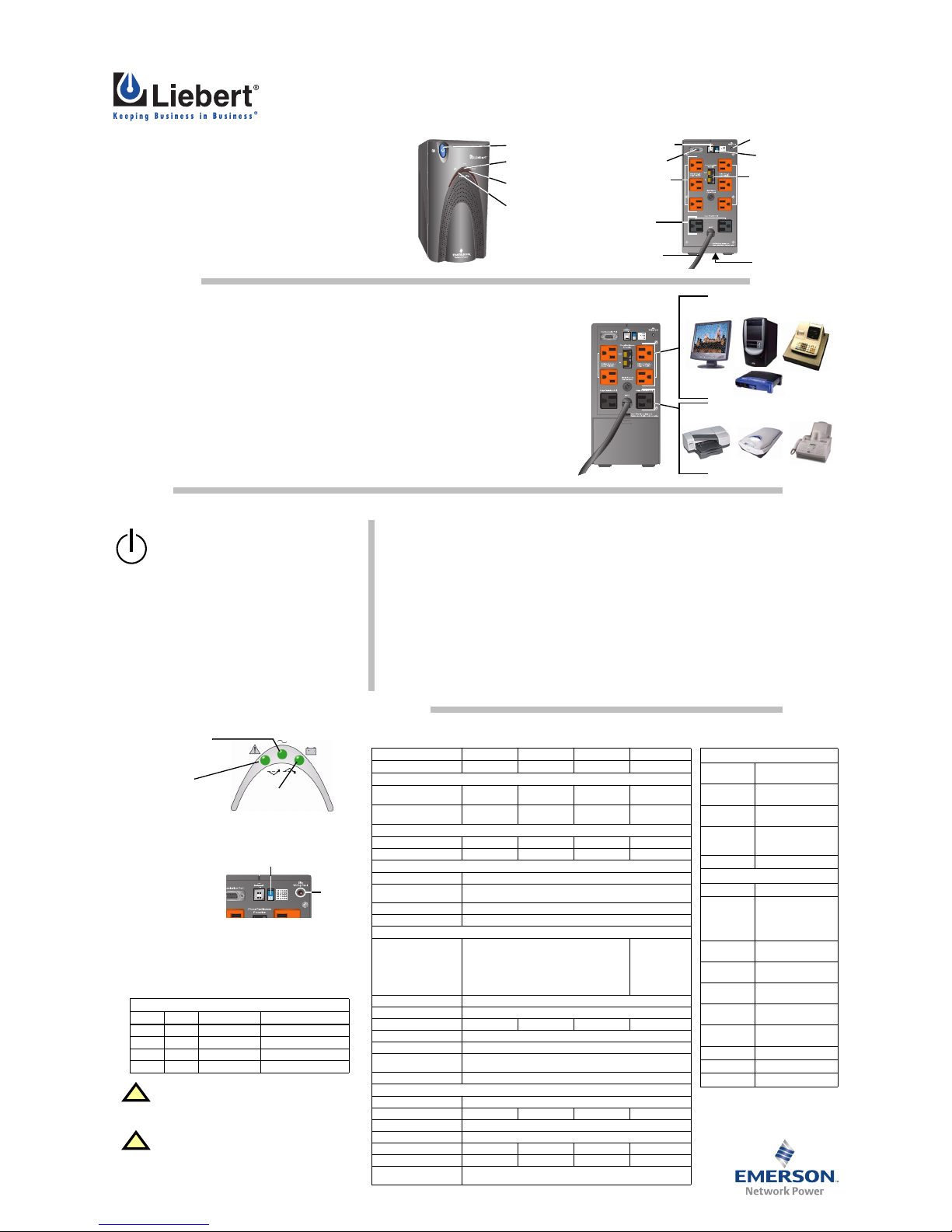
PowerSure PSA
PowerSure PSA
* Power ON/OFF/
Alarm Silence
* Fault Indicator
(Red/Green)
* Utility Indicator
(Green)
Battery Indicator *
(Green/Amber)
DIP switches **
*** USB port
*** DB-9 port
Site Wiring Fault *
Indicator (Red)
** Orange output receptacles (battery backup
and surge protection)
(4 receptacles on 350,
500 and 650VA models)
** Black output
receptacles (surge
protection only)
6-ft. (1.8m)
power cord
Battery cover plate
(on bottom for
650& 1000VA models)
(on rear of 350& 500VA
models)
Data Line ***
Protection
Connectors
For details, see :
* Controls and Indicators
** Installation
*** Communications
INSTALLATION
Read all safety, installation and operating instructions in the PowerSure family user manual on the included CD or
at www.liebert.com before operating the UPS. Adhere to all warnings on the unit and in the manual.
1. Install the UPS indoors in a controlled environment, where it cannot be accidentally turned off. Place it in an area
of unrestricted airflow around the unit, away from water, flammable liquids, gases, corrosives and conductive
contaminants. Maintain a minimum clearance of 4 inches (100mm) on each side of the UPS. Maintain an ambient temperature range of 32°F to 104°F (0°C to 40°C).
2. Plug the PSA’s power cord into an AC outlet. Check the Site Wiring Fault Indicator on the rear; if it is illuminated,
refer to the Troubleshooting section.
3. Plug any computers and monitors into the orange receptacles for battery backup and surge protection; other
office machines that do not exceed the capacity of the UPS may be plugged into either of the two (2) black
receptacles, which provide surge protection only.
4. Connect Phone/Fax/DSL/Internet/Modem devices to data line connectors.
5. Press and release the ON/ OFF/Alarm Silence button to turn on the UPS. The UPS will beep and the Utility Indicator will illuminate (green).
6. Turn on connected equipment.
Plug this type of equipment into
black receptacles ONLY
Plug computers, monitors & network hubs
into orange receptacles
Inkjet printers
Scanners
Fax machines
COMMUNICATIONS
The PowerSure PSA will communicate with your computer in either of two ways: over its DB-9 port through Liebert’s MultiLink
™
software or by USB through Microsoft® Windows® operating system features.
MultiLink supplies useful monitoring data, such as input voltage and battery level, and will perform an orderly shutdown of the computer system. Microsoft Windows XP and 2000 operating system utilities supply UPS status information and will perform an orderly computer shutdown. Check your computer’s OS features to dete rmine whether
it has power management capability.
For MultiLink Serial Communications
• Connect the provided MultiLink serial cable to the DB-9 ports on the rear of the UPS and on the rear of your
computer.
• Install the MultiLink software—the software, installation instructions and the user manual are on the CD included
in the PowerSure PSA package.
For USB Communications (with operating system power management)
• Connect the USB cable provided with the UPS to the USB ports on the PSA and your computer. The PSA will
work automatically with the built-in power management software on Windows XP and 2000 or later.
• All USB models are compatible with Microsoft Windows 2000, Windows XP and Macintosh
®
OS 10.2 or later.
CONTROLS AND INDICATORS
This button controls output power to the connected
load and has three functions:
• Turns the PowerSure PSA ON
• Turns the PowerSure PSA OFF
• Silences PowerSure PSA alarms
TURN THE UPS ON: Press and release the main ON/ OFF
button to start the UPS. An audible alarm will sound briefly.
TURN THE UPS OFF: When the PSA is ON, hold the main
ON/ OFF button down for more than 2 seconds to shut it down.
An audible alarm will sound briefly.
SILENCE AN ALARM: When a UPS alarm is active, press and
release the main ON/ OFF button to silence the audible alarm
(Exceptions: low battery, overload and overtemperature). DO
NOT hold the button down for more than 2 seconds or the PSA
will shut down.
CHECK THE PSA’S CONDITION: Three status indicators on
the front of the UPS illuminate to specify the status of the UPS
(see Troubleshooting section for details).
SITE WIRING FAULT INDICATOR (RED)
The Site Wiring Fault Indicator on the rear panel, as
shown, illuminates red
when the UPS detects a
line-neutral reversal or a
poor neutral-ground. (See
Troubleshooting Chart if
indicator is illuminated.)
TRANSFER VOLTAGE SELECTORS (DIP SWITCHES)
The two-position DIP switch control on the rear panel, shown
above, allows the operator to select the utility transfer voltage
at which the UPS will switch to battery power. The factory
default settings are 100VAC - 135VAC. DIP switch positions for
each voltage setting are:
DIP switch settings
Left Right Nominal Utility Setting
↑ Up ↑ Up 120VAC 85 - 145VAC (default)
↑ Up ↓ Down 110VAC 78 - 138VAC
↓ Down ↑ Up 127VAC 90 - 150VAC
↓ Down ↓ Down 120VAC 85 - 145 VAC
!
CAUTION
Never change the voltage settings while the UPS
is ON and powering connected loads. Change
DIP switches only when the UPS is OFF.
!
CAUTION
To ensure protection of the connected
equipment, the DIP switch settings should match
the nominal utility input voltage. DIP switch
settings not matching the nominal utility could
potentially damage connected equipment.
Fault Indicator
Green: Overload /
Overtemperature
Red: UPS fault
Utility Indicator
Green: N ormal operation
Amber: B uck/Boost
mode
Battery Indicator
Green: On battery
Amber: Battery
warning
DIP Switches
Site Wiring
Fault
Indicator
(Red)
Rear of UPS
SPECIFICATIONS
Model Number
PSA350MT-120 PSA500MT-120 PSA650MT-120 PSA1000MT-120
Power Rating VA/W
350VA/ 210W 500VA/ 300W 650VA/390 W 1000VA/ 600W
DIMENSIONS: in. (mm)
Unit
WxDxH
4.6x 7.7 x8.7
(116x196 x222)
4.6x 7.7x8.7
(116x196 x222)
4.6x 14.1 x8.7
(116x358x222)
4.6x 14.1x8.7
(116x358 x222)
Shipping
WxDxH
7.7x 12.2x11.5
(196x 310x293)
7.7x 12.2x11.5
(196x 310x293)
9.5x 19.7x12.4
(242x 500x316)
9.5x 19.7x12.4
(242x 500x316)
WEIGHT: lbs (kg)
Unit 16.8 (7.6) 17.2 (7.8) 20.7 (9.4) 29.7 (13.5)
Shipping 18.1 (8.2) 18.5 (8.4) 22.9 (10.4) 31.9 (14.5)
INPUT AC PARAMETERS
Surge Protection 570J
Voltage Range Without
Battery Operation
78VAC - 150VAC, DIP switch selectable
(see “DIP switch settings” on page 1)
Frequency Range 46.5 - 63.5 Hz (±0.1 Hz)
Input Power Cord 6 ft. (1.8m) attached, w/ NEMA 5-15 P
OUTPUT AC PARAMETERS
Output Receptacles
(4) NEMA 5-15R (orange)
Battery backup + surge protection;
(2) NEMA 5-15R (black)
Surge protection
(6) NEMA 5-15R
(orange) Battery
backup + surge
protection;
(2) NEMA 5-15R
(black) Surge
protection
Voltage (Normal mode) Nominal (110, 120, 127VAC) ±10%
Voltage (Battery mode) 120VAC ±8%
Output Current 2.9 A 4.2 A 5.4 A 8.3 A
Waveform (Battery mode) Stepped Sinewave
Frequency 50 Hz or 60 Hz; auto sensing
Overload Warning
(Normal & Battery modes)
>100%
Overload Shutdown >110%
BATTERY PARAMETERS
Type Valve-regulated, nonspillable, lead acid
QuantityxVoltagexRating (1)x12Vx7Ah (1)x12Vx9Ah (1)x12Vx9Ah (2)x12Vx7.5Ah
Transfer Time 4 - 6 ms typical
Backup Time: At 77°F (25°C), resistive loading, with fully charged batteries:
Full Load 8 minutes 8 minutes 5 minutes 5 minutes
Half Load 26 minutes 24 minutes 16 minutes 18 minutes
Recharge Time
6 hours to 90% of rated capacity,
after full discharge into resistive load
ENVIRONMENTAL (ALL MODELS)
Operating
Temperature
+32°F to +104°F
(0°C to +40°C)
Storage
Temperature
+5°F to +104°F
(-15°C to +40°C)
Relative
Humidity
0% to 95%, non-
condensing
Operating
Elevation
Up to 10,000 ft.
(3000m) at 86°F ( 30°C)
without derating
Audible Noise < 40 dBA, at 1 meter
AGENCY
Safety UL 1778, c-UL Listed
Surge
ANSI C62.41, Category
A, Level 3
(IEEE 587, Category A);
EN61000-4-5, Level 3,
Criteria A
ESD
EN61000-4-2, Level 3,
Criteria A
Susceptibility
EN61000-4-3, Level 3,
Criteria A
Electrical Fast
Transient/Burst
EN61000-4-4, Level 4,
Criteria A
Emissions
FCC Part 15, Subpart B,
Class B
Conducted
Immunity
EN61000-4-6, Level 3,
Criteria A
Harmonics EN61000-3-2
Flicker EN61000-3-3
Transportation ISTA Procedure 1A
Page 2
SL-23270QS (9/03) Rev. 0
TROUBLESHOOTING
The information below indicates various symptoms a user may encounter in the event
the PowerSure PSA experiences a problem.
Use this information to determine whether external factors caused the problem. See
Troubleshooting Chart for suggested remedy.
GUIDE TO STATUS INDICATORS
1. The Fault indicator illuminates, indicating the UPS
detected a problem.
2. An alarm sounds, alerting that the UPS requires
attention. The alarm can be silenced except for low
battery, overload and overtemperature warning
conditions.
3. Utility and/or Battery indicators may be illuminated as
a diagnostic aid to the operator, as shown below:
Fault
Indicator
Utility
Indicator
Battery
Indicator
Diagnosis/
Audible Alarm
—
Green
ON
—
Normal operation with utility power
present; no beep.
——
GreenONUPS is operating on battery; beep
every 10 seconds.
——
GreenONBattery test has been initiated; no
beep.
—
Green
ON
Amber
Flashing
Battery needs to be replaced; long
beep every minute.
——
Amber
Flashing
Low battery warning; beep every
half-second.
Green
Flashing
Green
ON
—
Overload warning, load is >100%;
beep every half-second.
Green
Flashing
——
Overload shutdown, load exceeds
UPS capacity (110%); continuous
beep.
Green
ON
Green
ON
—
Overtemperature (overtemp)
warning; beep every 5 seconds
(Normal mode).
Green
ON
—
Green
ON
Overtemperature (overtemp)
warning; beep every 5 seconds
(Battery mode).
Green
ON
——
Overtemperature (overtemp)
shutdown; long beep every
5 seconds.
Red
Flashing
Green
ON
—
UPS is on, fault warning;
continuous beep.
Red
ON
——
UPS has failed & shut down;
continuous beep.
Fault
Indicator
Utility
Indicator
Battery
Indicator
MAINTENANCE
The PowerSure PSA UPS requires very little maintenance. Follow these practices to
prevent problems.
CLEANING THE UPS
The following will help ensure trouble-free operation for years:
• Vacuum dust from the ventilation intake occasionally.
• Wipe the cover periodically with a dry cloth.
MAINTAINING BATTERIES
The batteries are valve-regulated, nonspillable, lead acid and must be kept charged to
retain their design life. The UPS continuously charges the batteries when connected to
the utility supply, even while the UPS is switched off.
When storing the UPS, it is recommended to plug in the UPS for at least 24 hours every
four to six months to ensure full recharge of the batteries.
BATTERY REPLACEMENT
This UPS is equipped with internal “hot swappable” batteries that the user can replace
without shutting down the UPS or connected loads.
!
CAUTION
A battery can present a risk of electrical shock and high short circuit
current. The following precautions should be observed before replacing
the batteries:
• Remove rings, watches, and other metal objects.
• Do not lay tools or other metal objects on top of the batteries.
• If the battery replacement kit is damaged in any way or shows signs
of leakage, contact your local dealer or Liebert representative immediately.
• Do not dispose of batteries in a fire. The batteries may explode.
• Dispose of old batteries according to local codes.
NOTE
Caution should be exercised when replacing the batteries because the
load is unprotected from disturbances and power outages during this
procedure.
TROUBLESHOOTING CHART
If the UPS fails to operate properly, turn off the unit and repeat the steps in the Installation section of this manual. If the problem persists, refer to the chart below:
Problem Cause Solution
UPS
will
not
start
Overload/Short
Circuit
Check the circuit protector on the rear of the
UPS. If it is tripped, reset it and restart the
UPS.
For further help, call your local dealer,
Liebert representative or the Liebert
Worldwide Support Group.
Battery disconnected
or is completely
discharged
Check for proper connection of battery or
batteries.
UPS starts
on battery,
but will
not switch
to AC
UPS not plugged in Plug in the power cord securely.
Circuit protector
tripped
Reset the circuit protector and restart the
UPS.
Power not available
at utility receptacle
Have the utility checked by a qualified
electrician.
Input voltage
below threshold
Wait until the voltage rises to an appropriate
level or have the utility checked by a
qualified electrician.
AC overvoltage
Wait until voltage lowers to an appropriate
level or have the utility checked by a
qualified electrician.
UPS
shuts
down,
Fault
Indicator
lit
Overload/Short
Circuit
Check the circuit protector on the rear of the
UPS. If it is tripped, reset it and restart the
UPS.
If the problem persists, disconnect some of
the equipment from your UPS—the total
wattage of your equipment must not exceed
the capacity of the UPS.
For further help, call your local dealer,
Liebert representative or the Liebert
Worldwide Support Group.
Internal UPS fault
High temp shutdown
Make sure that the UPS is operating in 32°F
to 104°F (0°C to 40°C) and that it has
adequate ventilation.
MultiLink shutdown
Consult the MultiLink user manual or contact
your LAN administrator.
Site Wiring
Fault
Indicator
illuminated
Line-neutral
reversal,
Poor ground
connection
Have the utility checked by a qualified
electrician.
UPS not
providing
expected
back-up
time
Overload Reduce load.
Battery not charged
due to a recent
outage
Recharge battery.
Battery needs to be
replaced
Replace battery.
PRODUCT WARRANTY REGISTRATION
To register for warranty protection:
• Visit the Quick Links section of our
Web site at:
http://www.liebert.com
• Click on Product Warranty
Registration and fill in the form.
If you have any questions, please
contact us at:
US: 800-222-5877
Outside the US: 614-841-6755
BATTERY REPLACEMENT
Replacement requires removing the battery cover plate on the bottom of the UPS. No
tools are needed.
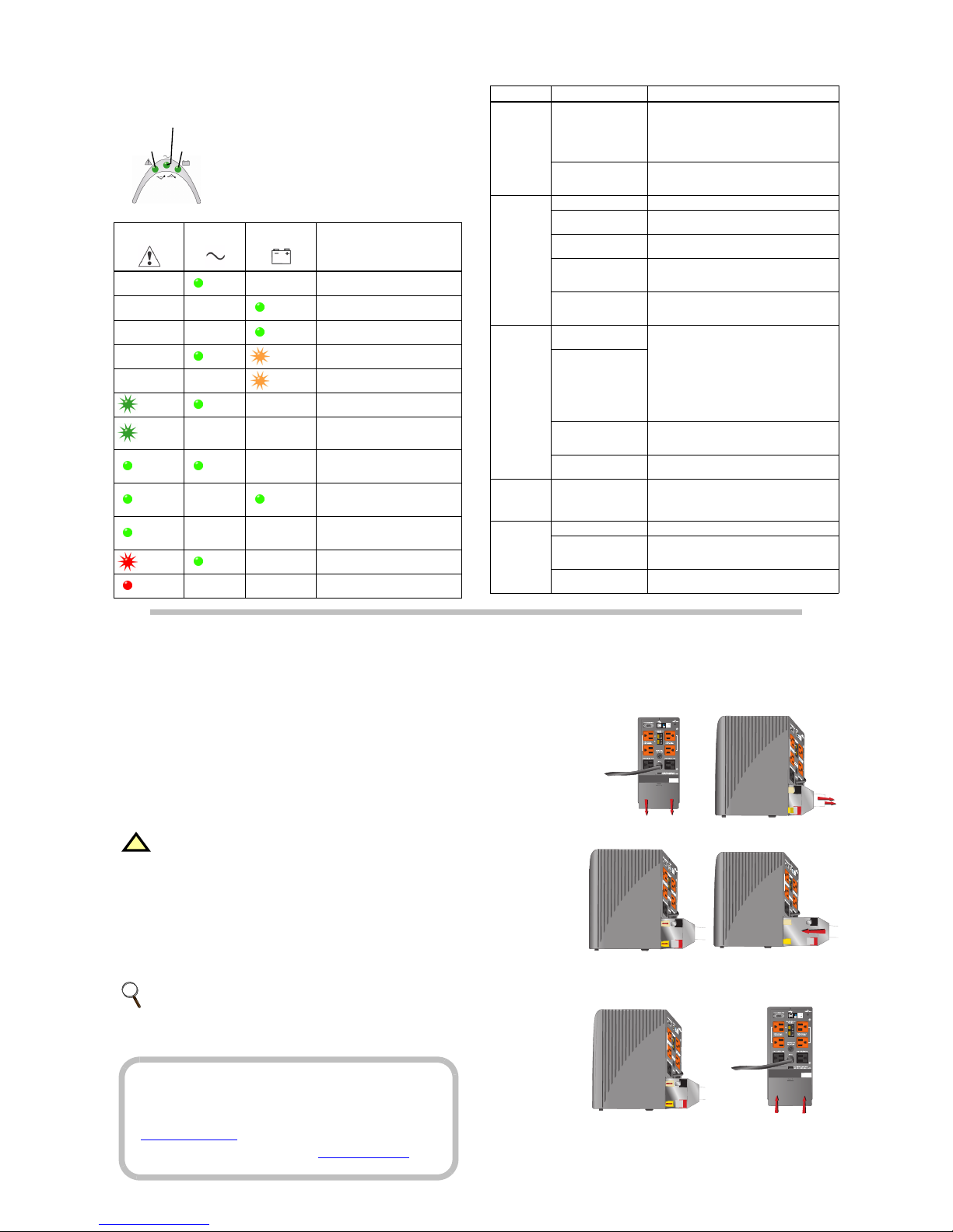
To replace the batteries:
1. Remove the battery
cover plate on the
back/bottom of the
UPS (Figure 1).
2. Pull the white tabs
towards you to
remove the battery
from the UPS
(Figure 2).
Figure 1 Figure 2
3. Disconnect the insulated connectors
from the battery terminals (Figure 3).
4. Insert a new batte ry
pack, and push the
connectors onto the
battery terminals
(black to black & red
to red) (Figure 4).
Figure 3 Figure 4
NOTE: There may be a small spark at the battery terminals when reconnecting
the connectors. This is normal and will not harm you or the UPS.
5. Push the battery
pack into the UPS
(Figure 5).
6. Reattach the battery
cover plate
(Figure 6).
Figure 5 Figure 6
 Loading...