

Page 1
POWER PROTECTION
USER M
A
NUAL
English
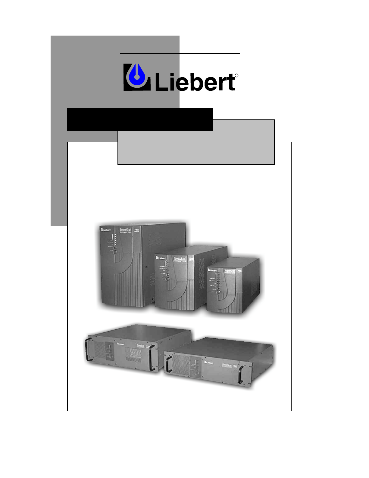
700-2200 VA
120 V
PowerSure™ Interactive
R
Page 2

2
IMPORTANT SAFETY INSTRUCTIONS
WARNING: Do not attempt to service this product yourself except to replace
the battery. Opening or removing the cover may expose you to dangerous
voltages, even when the AC cord is disconnected from the electrical outlet.
Refer all servicing to qualified service personnel.
1. SAVE THESE INSTRUCTIONS. THIS MANUAL CONTAINS
IMPORTANT INSTRUCTIONS THAT SHOULD BE FOLLOWED
DURING INSTALLATION AND MAINTENANCE OF THE
UNINTERRUPTIBLE POWER SYSTEM (UPS) AND BATTERIES.
CONSERVER CES INSTRUCTIONS. CETTE NOTICE CONTIENT
DES INSTRUCTIONS IMPORTANTES CONCERNANT LA
SÉCURITÉ.
2. This product is not intended for use with life support and other
U.S. FDA designated “critical” devices. See Limited Warranty.
3. CAUTION: A BATTERY PRESENTS A RISK OF ELECTRICAL
SHOCK OR BURN FROM HIGH SHORT CIRCUIT CURRENT.
OBSERVE PROPER PRECAUTIONS.
ATTENTION: UNE BATTERIE PRESENT UN RESQUE DE CHOC
ÉLECTRIQUE OU DE BRÛLURE PAR TRANSFERT D’ÉNERGIE.
SUIVRE LES PRÉCAUTIONS QUI S’IMPOSENT.
4. WHEN REPLACING THE BATTERIES, USE THE SAME NUMBER
AND TYPE OF BATTERIES. PROPER DISPOSAL OF BATTERIES IS
REQUIRED. REFER TO YOUR LOCAL CODES FOR DISPOSAL
REQUIREMENTS.
POUR LE REMPLACEMENT, UTILISER LE MÉME NOMBRE ET
TYPE DE BATTERIES. L’ÉLIMINATION DES BATTERIES EST
RÉGLE-MENTÉE. CONSULTER LES CODES LOCAUX À CER
EFFET.
5. Read all safety and operating instructions before operating the UPS.
Adhere to all warnings on the unit and in this manual. Follow all
operating and user instructions.
6. Turn the UPS off and unplug it before cleaning. Use only a soft cloth,
never liquid or aerosol cleaners.
7. The UPS is designed for data processing equipment. Do not plug
appliances, such as hair dryers, heaters, vacuum cleaners, or electric
drills, into the UPS output receptacles.
8. WARNING: Do not modify input cable. Consult your dealer if
connector does not match the utility receptacle. The UPS must be
grounded at all times while in use. Turn the UPS off before unplugging
Page 3

3
it, or the safety ground will be removed. Operate UPS only from a
properly grounded 120 VAC outlet (2 wire plus ground).
9. The UPS is equipped with a grounded NEMA 5-15P or L5-30P input
power plug (depending upon model). Do not defeat the safety purpose
of this plug. If unable to fully insert the plug into the wall outlet, contact
a qualified electrician for assistance.
10. Route power supply cords so they are not walked on or pinched.
11. Never block or insert any object into the ventilation holes or other
openings. Maintain a clearance of four (4) inches (102 mm) around the
UPS for proper air flow and cooling.
12. Always turn off the UPS and unplug it before starting the battery
replacement procedure. Servicing of batteries should be performed or
supervised by personnel knowledgeable of batteries and the required
precautions. To replace batteries, refer to the battery replacement
procedure. If you feel unqualified to replace the batteries, do not open
the battery door. Refer all servicing to qualified service personnel.
13. CAUTION: Do not open or mutilate the batteries. Released
electrolyte is harmful to skin and eyes and may be toxic.
Page 4

4
INTRODUCTION & SYSTEM DESCRIPTION
Congratulations on your choice of the Liebert PowerSure™ Interactive
Uninterruptible Power System (UPS). It provides conditioned power to
microcomputers and other sensitive electronic equipment.
Upon generation, AC power is clean and stable. However, during transmission it
may be subject to voltage sags, spikes, or complete power failure which may
interrupt computer operations, cause data loss, or even damage equipment. The
PowerSure™ Interactive protects equipment from these disturbances.
The PowerSure™ Interactive comes in nominal power ratings of 700, 1000, 1400,
or 2200 VA. Complete specifications appear near the end of this section.
The PowerSure™ Interactive is a compact, “line interactive” UPS. A “line
interactive” UPS continuously conditions and regulates its output voltage, whether
the utility power is present or not. It supplies connected equipment with clean
sinewave power, to simulate as much as possible, the power generated by the
utility. Sensitive electronic equipment operates best from sinewave power.
For ease of use, the PowerSure™ Interactive contains a light emitting diode (LED)
bar display to indicate “load percentage” or “battery capacity” depending upon the
mode of operation. It also provides self diagnostics, a combination alarm
silence/battery test button, and two levels of alarms when the unit is operating on
battery.
The PowerSure™ Interactive has an interface port for communications between the
UPS and a LAN server or other computer system. This port provides detailed
operating information including voltages, currents, and alarm status to the host
system when used in conjunction with Liebert SiteNet® software. SiteNet®
software can also remotely control UPS operation.
CAUTION: This equipment has been tested and complies with limits for a Class A
digital device, pursuant to Subpart B of Part 15 of FCC rules. These limits provide
reasonable protection against harmful interference when the equipment is operated
in a commercial environment. This equipment generates, uses, and can radiate
radio frequency energy. If it is not installed and used in accordance with the
instruction manual, it may cause harmful interference to radio communications.
Operation of this equipment in a residential area is likely to cause harmful
interference which the user must correct at his own expense.
Page 5
5
MAJOR COMPONENTS
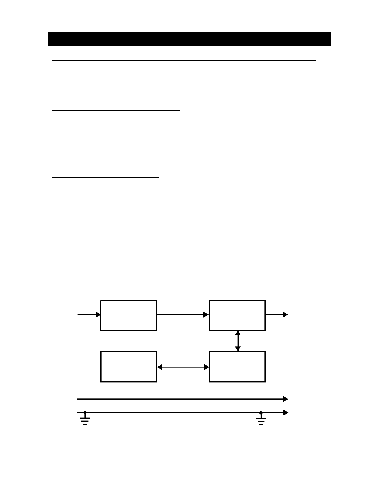
TRANSIENT VOLTAGE SURGE SUPPRESSION (TVSS) AND EMI/RFI FILTERS
These UPS components provide surge protection and filter Electromagnetic
Interference (EMI) and Radio Frequency Interference (RFI). They minimize any
surges or interference present in the utility line and keep the sensitive equipment
protected.
AUTOMATIC VOLTAGE REGULATOR
In normal operation, the Automatic Voltage Regulator (AVR) passes utility AC
power to the connected load. When utility power voltage is outside acceptable
limits, the AVR activates. It raises undervoltage power and lowers overvoltage
power. This keeps the UPS output voltage within the connected equipment’s
tolerances and allows wide utility voltage fluctuations without utilizing battery
power.
BI-DIRECTIONAL CONVERTER
In normal operation, the bi-directional converter “converts” utility AC power into
regulated DC power to “float” charge the battery system. Upon a utility power
failure, the bi-directional converter receives its required energy from the battery and
“inverts” it into precise, regulated sinewave AC power. Charging takes place
whenever the UPS is plugged into the wall outlet whether it is ON or OFF and utility
power is within acceptable limits.
BATTERY
The PowerSure™ Interactive utilizes valve regulated, nonspillable, lead acid
batteries. At typical room temperatures and with the UPS float charging, the
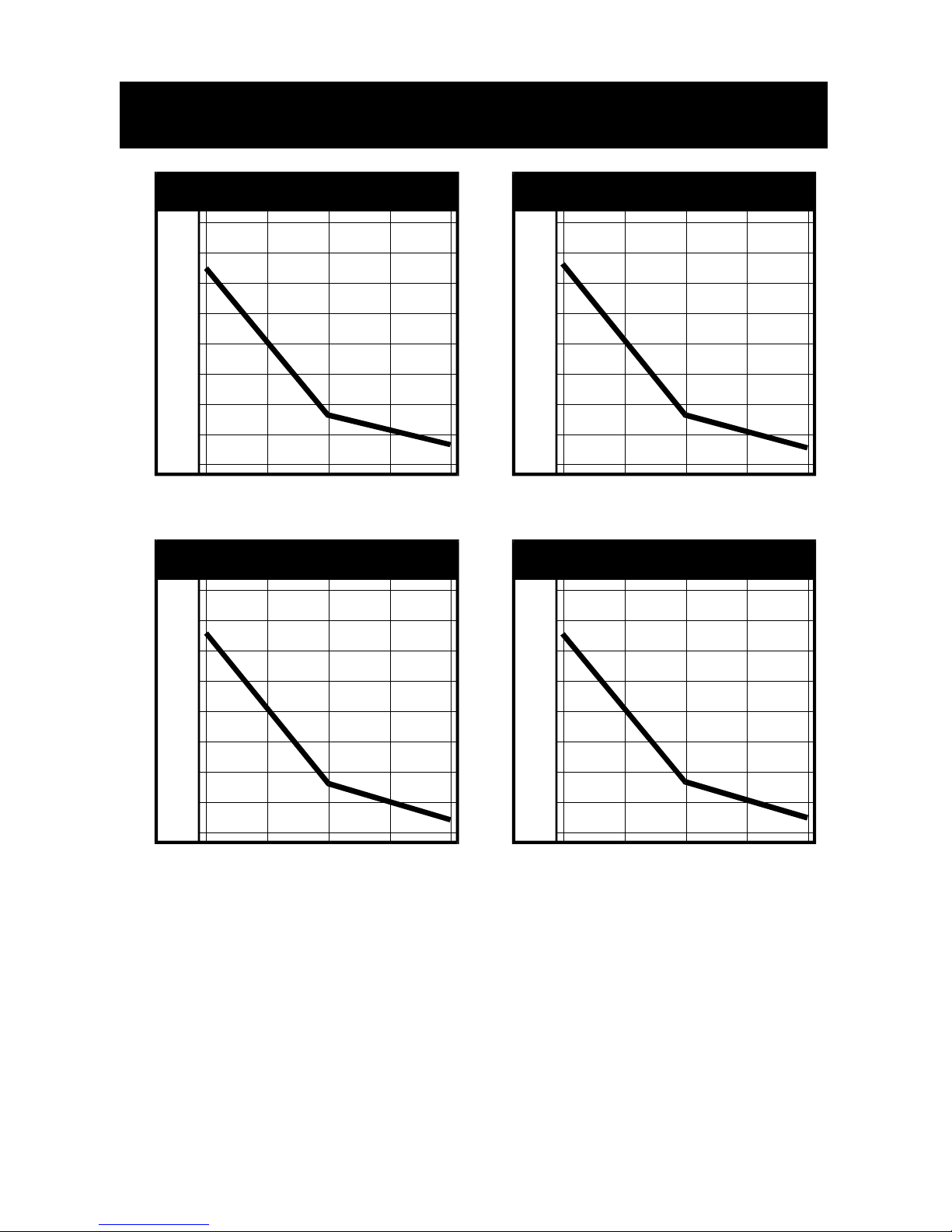
battery system will last many years. For battery run times, refer to the Typical
Battery Discharge Curves.
INPUT OUTPUT
TVSS
and
EMI/RFI Filters
Automatic
Voltage
Regulator
Bi-Directional
Converter
Battery
L
L
N
N
G
G
Page 6

6
MINI-TOWER INSTALLATION
1. Unpack the UPS carefully noting the packing method. Retain the box and
packing material for possible future shipment.
CAUTION: The UPS is heavy (see specifications). Take proper precautions
when lifting or moving it.
2. Visually inspect the UPS for freight damage. Report damage to the carrier and
your dealer.
3. Locate the UPS indoors where it cannot be accidentally disconnected. Locate
it in an area with unrestricted airflow, away from water, flammable liquids,
gases, corrosives, or conductive contaminants. Maintain a minimum of four (4)
inches (102 mm) clearance around the UPS. Maintain an ambient temperature
range of 32° to 104° F (0° to 40° C).
NOTE: UPS operation in temperatures above 77° F (25° C) reduces battery
life.
4. Ensuring load equipment is turned off, plug all loads into the UPS output
receptacles.
5. Plug the UPS into a dedicated wall receptacle properly protected by a circuit
breaker or fuse in accordance with the National Electric Code (ANSI/NFPA 70)
or local codes. Use a 15 amp rated device for the 700, 1000, or 1400 VA
units, and a 30 amp device for the 2200 VA unit. The wall receptacle must be
grounded.
6. Turn on the UPS, by pressing the On/Off button, then turn on the connected
load equipment. The UPS is ready for normal operation.
Page 7

7
RACKMOUNT INSTALLATION
1. Unpack the UPS carefully noting the packing method. Retain box and packing
material for possible future shipment.
CAUTION: The UPS is heavy (see specifications). Take the proper
precautions when lifting or moving the UPS.
2. Visually inspect the UPS for freight damage. Report any damage to the carrier
and your dealer.
3. Locate the UPS indoors where it cannot be accidentally disconnected. Locate
it in an area with unrestricted airflow, away from water, flammable liquids,
gases, corrosives, or conductive contaminants. Maintain a minimum of four (4)
inches (102 mm) clearance in front and rear of the UPS. Maintain an ambient
temperature range of 32° to 104° F (0° to 40° C).
NOTE: UPS operation in temperatures above 77° F (25° C) reduces battery
life.
4. Gently lay UPS on its bottom side so that the front bezel is facing you.
5. The Rackmount UPS must be supported by a shelf or rails. The front bezel will
not support the weight of the UPS.
CAUTION: To increase the stability of the rack enclosure, place the UPS in the
lowest possible rack position.
6. Refer to the Installation instructions supplied with the Rack Slide or Shelf Kits
to complete the installation procedures.
7. After the UPS has been installed in the Rack enclosure, plug the UPS into a
dedicated wall receptacle properly protected by a circuit breaker or fuse in
accordance with the National Electric Code (ANSI/NFPA 70) or local codes.
Use a 15 amp rated device for the 700, 1000, or 1400 VA units, and a 30 amp
device for the 2200 VA unit. The wall receptacle must be grounded.
8. Ensuring load equipment is turned off, plug all loads into the UPS output
receptacles.
9. Turn on the UPS, by pressing the On/Off button, then turn on the connected
load equipment. The UPS is ready for normal operation.
Page 8

8
CONTROLS AND INDICATORS
On/Off Button
The On/Off button controls output power to connected load(s).
CAUTION: Pressing the On/Off button when AC utility is not present will cause the
UPS to begin operating from battery. This should not be performed unless the UPS
input is connected to a properly grounded receptacle.
Load/Battery Level Indicators (ALL GREEN)
The Load/Battery Level Indicators have dual functions. During normal mode
operation, LED indicators display electrical load placed upon the UPS; and during
battery mode operation, LED indicators display battery capacity remaining. Each
LED designates a 25% load or battery capacity increment. All four LED indicators
illuminate at full load/battery capacity. If the UPS becomes loaded beyond full
rating, the top LED indicator will flash continuously while an alarm sounds.
Utility/Battery Status Indicator (GREEN)
An illuminated LED indicates the power button is on and utility power is available.
A flashing LED along with an alarm signifies utility voltage is out of specification
and UPS is operating in battery mode.
Utility High/Low Indicator (AMBER)
An illuminated LED indicates the UPS is correcting utility power, due to a utility
overvoltage or undervoltage condition.
Fault Indicator (GREEN)
The Fault indicator is the second uppermost LED (contained in load/battery level
indicators). A flashing LED indicates the UPS has detected a problem. An alarm
sounds to alert that the UPS requires attention. Refer to Troubleshooting Guide.
Alarm Silence/Battery Test Button
The Alarm Silence/Battery Test button serves a dual purpose. During normal mode
operation, press button for at least one half second to test capacity of the battery
system. The UPS will operate in battery mode for approximately 15 seconds. The
illuminated LED indicators in Load/Battery Level determine battery mode capacity
in 25% increments.
During battery mode operation or active alarm condition, this button functions as
the alarm silence feature. Pressing this button for at least one half second will
silence the alarm. After the alarm is silenced, the PowerSure™ Interactive will
reactivate the alarm system to alert of additional problems. The low battery alarm
is the single alarm that cannot be silenced.
During a Battery Test, if the top two LEDs do not illuminate allow the UPS to
recharge the batteries for 24 hours. After 24 hours, retest the batteries. If the
batteries have been retested and the top two LEDs still do not illuminate, contact
your dealer or Liebert Technical Support (LTS) for a battery replacement kit.
Site Wiring Fault Indicator (RED)
An illuminated LED indicates the UPS has detected a miswired utility receptacle.
Contact a qualified electrician for assistance.
Page 9
9
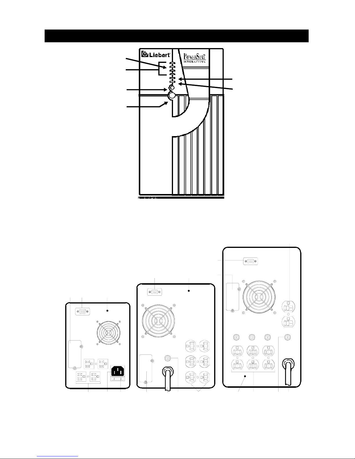
POWERSURE™ INTERACTIVE MINI-TOWER
4
26
2
64
2
1
1
3
5
4
3
5
1
6
1
5
3
700 VA 1000 / 1400 VA 2200 VA
Fault Indicator
Load/Battery
Level Indicators
Alarm Silence/
Battery Test Button
On/Off Button
Utility High/Low
Indicator
Utility/Battery
Status Indicato
r
1- Output Receptacles
2- DB-9 Interface Port
3- AC Inlet
4- Intellislot™ Communications Port
5- Circuit Protector or Fuse
6- Site Wiring Fault Indicator
Page 10
10
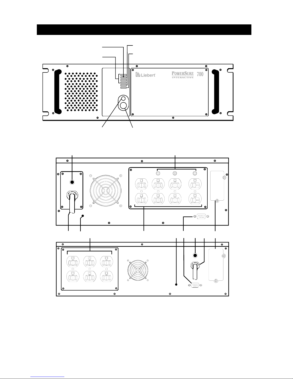
POWERSURE™ INTERACTIVE RACKMOUNT
2200 Model
1 3
4
62
3
6
1
5
5
5
700-1400 Models
*700 Model has detachable cord
1- Output Receptacles
2- DB-9 Interface Port
3- AC Inlet
4- Intellislot™ Communications Port
5- Circuit Protector or Fuse
6- Site Wiring Fault Indicator
On / Off
Alarm Silenc e
Load / Battery
Utility High / Low
Utility
R
On / Off Button
Alarm Silence /
Batter
y
Test Button
Utility/ Battery
Status Indicator
Utility High
/
Low Indicator
Load / Battery
Level Indicators
Fault Indicator
Page 11
11
OPERATION
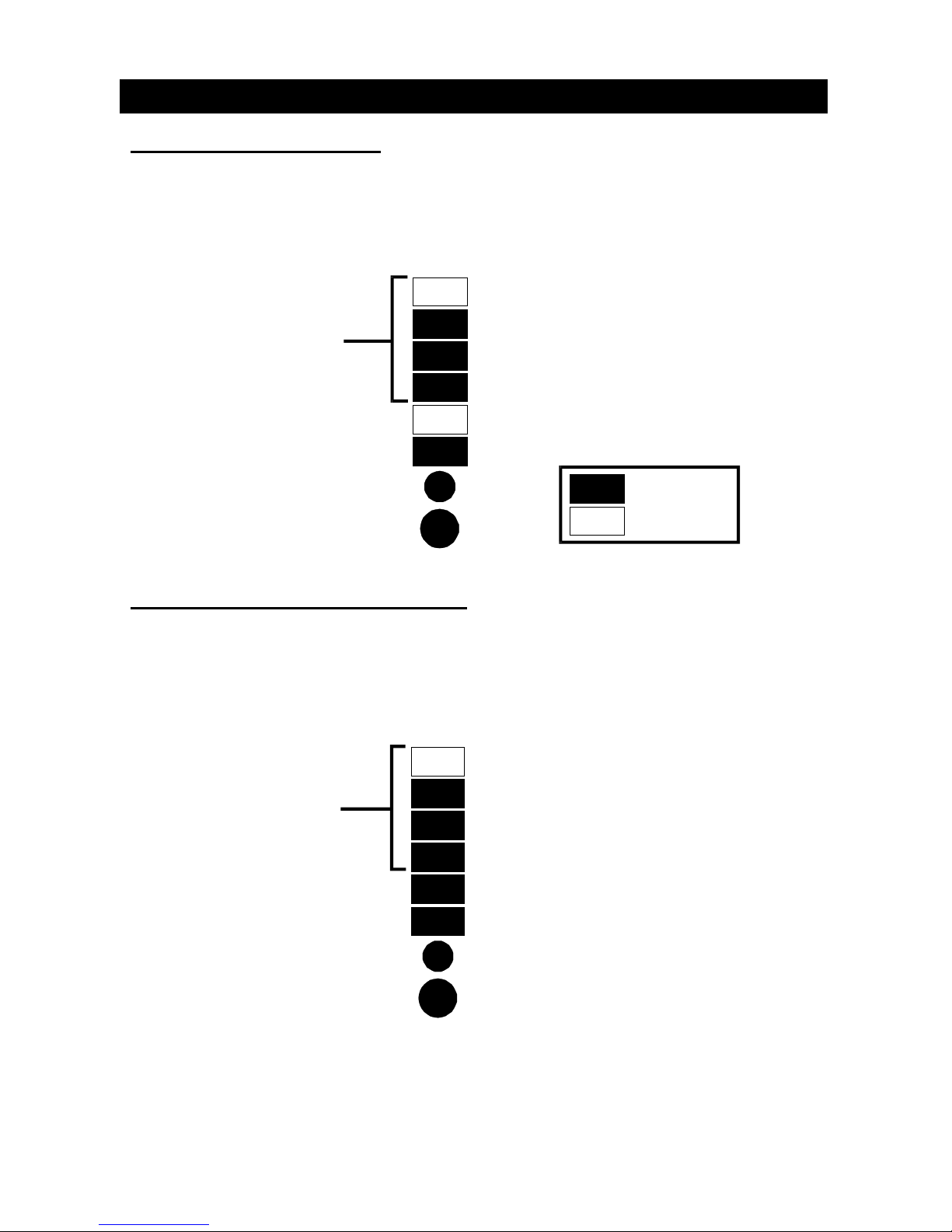
NORMAL MODE OPERATION
During normal operation, utility power provides energy to the UPS. The filters and
the power conditioning circuit process this power to provide computer grade power
to connected loads. The UPS maintains the batteries in a fully charged state.
The front panel displays the percentage of load on the UPS output. The figure
below indicates approximately 51-75% loading.
UTILITY HIGH/LOW MODE OPERATION
If high or low voltage conditions occur, the PowerSure™ Interactive UPS will
automatically correct the utility voltage by either lowering or raising the input
voltage condition. The UPS will continue to correct these conditions indefinitely,
without draining battery power.
The figure below indicates approximately 51-75% loading while automatically
correcting the utility voltage.
Load/ Battery
Level Indicators
Utility High/Low
Utility
Alarm silence/Test
On/Off
76% to 100% load
(Flashes to indicate overload)
51% to 75% load
26% to 50% load
0% to 25% load
LED ON
LED OFF
Load/ Battery
Level Indicators
Utility High/Low
Utility
A
larm silence/Test
On/Off
Page 12
12
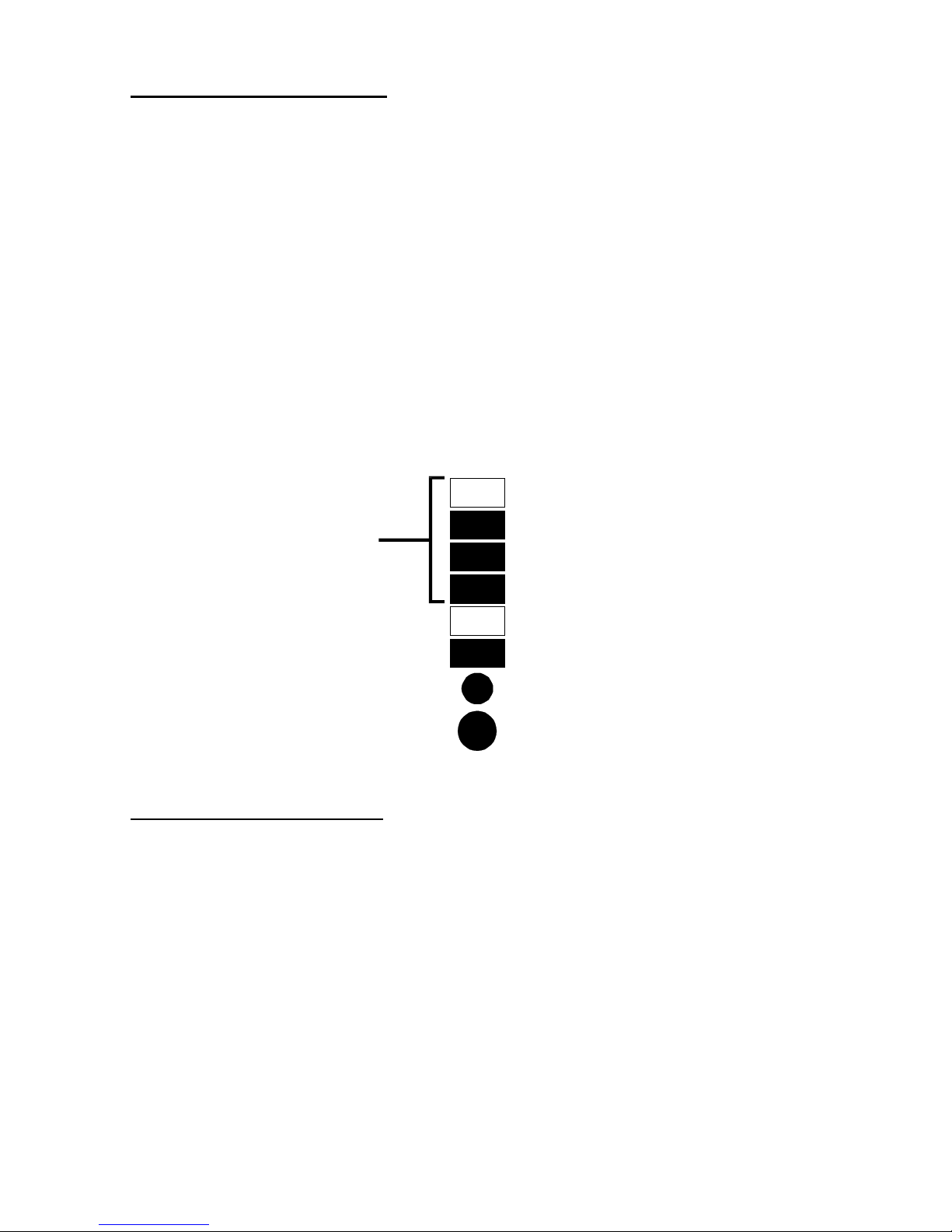
BATTERY MODE OPERATION
Battery mode occurs in event of extreme input conditions or complete utility failure.
The battery system along with the bi-directional converter generates power for the
connected load.
During battery mode an alarm sounds every 10 seconds. This will change to 2
beeps every 5 seconds when battery runs low (approximately 2 minutes
remaining). Each load/battery level indicator represents a 25% capacity level. As
capacity decreases, fewer indicators remain illuminated. Utility LED will flash every
second indicating the UPS is operating from battery mode.
Battery mode supports a full rated load for approximately 5 minutes before it shuts
down. To increase this time, turn off non essential pieces of equipment (such as
idle computers and monitors).
WARNING: Turning off the UPS while in battery mode will result in loss of output
power.
The figure below displays approximately 51-75% battery capacity remaining.
BATTERY RECHARGE MODE
The UPS resumes normal operation once utility power is restored. At this time, the
bi-directional converter begins recharging the battery whether the UPS in ON or
OFF.
Load/ Battery
Level Indicators
Utility High/Low
Utility
Alarm silence/Test
On/Off
76% to 100% loa
d
51% to 75% load
26% to 50% load
0% to 25% load
(Flashes to indicate low battery)
(Flashes every second)
Page 13
13
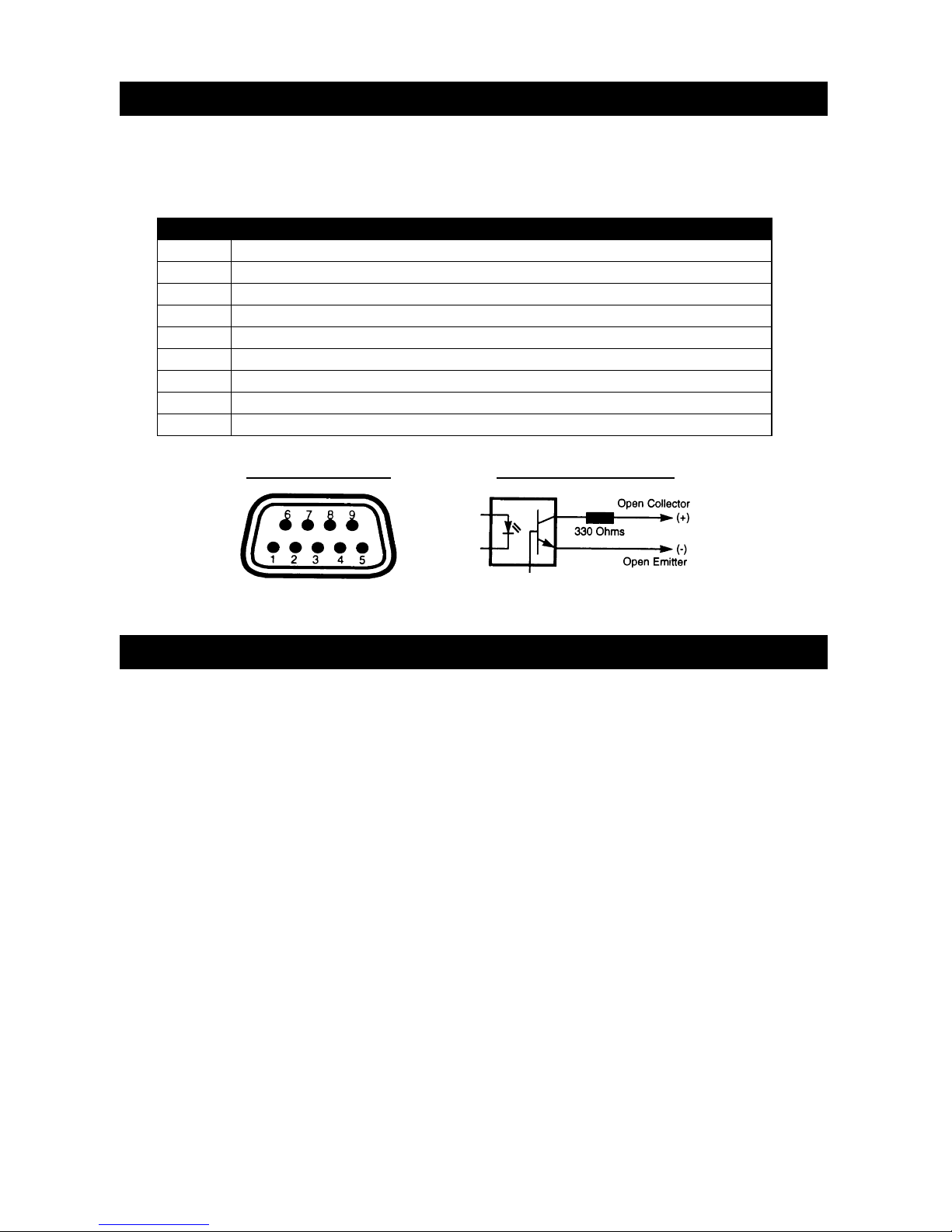
COMMUNICATIONS INTERFACE PORT
The PowerSure™ Interactive UPS contains a standard DB-9F recepticle located on
the rear of the UPS unit. Several signals are provided on this port and are
assigned as follows:
PIN ASSIGNMENT DESCRIPTION
1 Low Battery (open collector)
2 UPS TxD (typical RS-232 levels)
3 UPS RxD (typical RS-232 levels)
4 Remote Shutdown (5-12V DC, 1.0 mA. max.); battery operation
5 Common
6 No connection
7 Low Battery (open emitter)
8 Utility Fail (open emitter)
9 Utility Fail (open collector)
*Maximum voltage and current on pins 1, 7, 8, 9 is 80V DC; 10.0 mA.
UPS MONITORING
The PowerSure™ Interactive UPS has the capability of being monitored with stand
alone computers, network workstations, network servers, or UNIX hosts via the DB9 female connector located on the rear of the UPS.
This capability is used in applications requiring the UPS to provide status and
power monitoring information to the computer system. For example, during a utility
power failure, the information can be used by the computer’s operating system or
application program to automatically save information in buffers, to close files, and
shut down operations prior to battery capacity depletion.
Monitoring of the UPS via a computer system is easily made with a Liebert
SiteNet® 1 shutdown kit (sold separately). Consult your local Liebert
representative to determine the correct software kit for your application. The kit
includes special purpose cable and shutdown software.
Collector to Emitter*Pin Assignment
Page 14

14
UPS INTELLIGENT COMMUNICATIONS
The PowerSure™ Interactive UPS has the capability to communicate intelligently
with stand alone computers, network workstations, network servers, or UNIX hosts
via the DB-9 female connector located on the rear of the UPS. By purchasing the
optional Liebert SiteNet® 2 software package (sold separately), intelligent
communications allows the following capabilities:
• Quantitative monitoring of utility and UPS power
• Quantitative monitoring of internal UPS parameters
• Periodic tests of battery quality and replacement notification
• Timed and delayed shutdown of the UPS
• Logging of power disturbances and anomalies
Contact your local Liebert representative, dealer, or reseller for more information
about SiteNet® 2 software.
UPS INTELLISLOT™ COMMUNICATIONS
The PowerSure™ Interactive UPS contains an Intellislot™ communications port for
the optional internal communications, such as the Ethernet SNMP card. Optional
SiteNet® SNMP Manager software is available to allow communication through
several network management systems. Contact your local Liebert representative,
dealer, or reseller.
CAUTION: TO MAINTAIN SAFETY (SELV) BARRIERS AND FOR
ELECTROMAGNETIC COMPATIBILITY, SIGNAL CABLES SHOULD BE
SEGREGATED AND SEPARATELY RUN FROM ALL OTHER POWER CABLES,
WHERE APPLICABLE.
MAINTENANCE
The PowerSure™ Interactive UPS requires very little maintenance. The batteries
are valve regulated, nonspillable, lead acid, and require that they be kept charged
to obtain their designed life. Whether ON or OFF, the UPS continuously charges
the batteries when connected to the utility supply.
When storing the UPS for any length of time, it is recommended to plug the UPS in
for at least 24 hours every four to six months to ensure full recharge of the
batteries.
The PowerSure™ Interactive UPS is designed to allow the user to safely replace
the batteries. Read the safety cautions before proceeding. Contact your local
Liebert representative, dealer, or reseller to obtain the appropriate replacement
battery kit.
Page 15

15
MINI-TOWER BATTERY REPLACEMENT
CAUTION- A battery can present a risk of electrical shock and high short circuit
current. The following precautions should be observed before replacing the batteries:
• Turn off and disconnect the UPS from utility power prior to opening the battery
replacement door.
• Remove rings, watches, and other metal objects.
• Use a Phillips (cross head) screwdriver with insulated grips.
• Do not lay tools or other metal objects on top of the batteries.
• If the battery replacement kit is damaged in any way or shows signs of leakage,
contact your dealer immediately.
• Do not dispose of batteries in a fire, the batteries may explode.
• If you feel unqualified to replace the battery, do not open the battery door. Call
Liebert Technical Support (LTS). World Wide Technical Support numbers are located
at the end of this section.
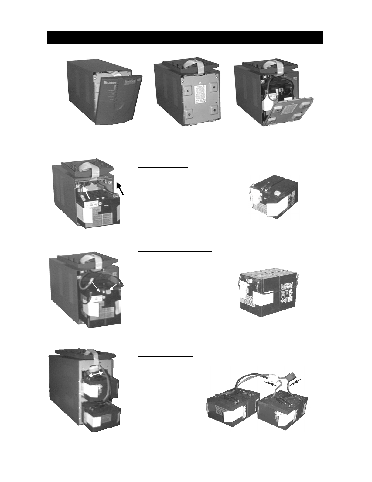
1. Grasp the front bezel near the top and pull forward.
2. Rotate the bezel upward and lay it on top of the UPS.
3. Loosen the two screws at top of the battery door and remove door by pulling it
forward slightly and lifting it off. Lay battery door and screws aside for
reassembly.
4. 700/1000/1400 VA models: gently pull battery wiring out and disconnect the
two wires [one red (+) and one black(-)].
2200 VA models: pull apart connectors A and B.
5. Grasp white pull-tabs located on sides of the front battery, and pull batteries
out of the UPS.
6. Unpack new batteries taking care not to destroy the packing.
7. Slide new batteries into the cavity, noting the white pull-tabs are facing
outward.
8. 700/1000/1400 VA models: connect the battery wires; first red to red, then
black to black.
2200 VA models: first connect top battery connector A to bottom battery
connector A; then connect UPS connector B to the top battery connector B.
NOTE: There will be a small spark when connecting the black connectors on
700-1400 VA models, and connector B on the 2200 VA model. This is normal
and will not harm you or the UPS.
9. Replace battery door by inserting the two metal tabs into the slots at the base
of the UPS, and pushing it closed at the top. Tighten the two screws to lock
the battery door closed.
10. Flip the bezel back into place, and align bottom clips to the lower slots in the
battery door. Once aligned, push bezel back onto the UPS until it latches into
position. This may require a gentle tap.
11. Dispose/Recycle of old batteries in accordance with your local laws and
regulations.
Page 16
16
MINI-TOWER BATTERY REPLACEMENT
700 VA Model
To Disconnect: Gently pull wiring
away
To Connect: Connect red wire to
red terminal, then black wire to
black terminal by pushing towards
connector
1000/1400 VA Model
To Disconnect: Gently pull
wiring away
To Connect: Connect red
wire to red terminal, then black
wire to black terminal by
pushing upward
2200 VA Model
To Disconnect:
Pull apart
connections A & B
To Connect:
Push connections
A together &
connections B
together
Pull bezel forward Rotate bezel on top Remove battery door
A
B
Page 17

17
RACKMOUNT BATTERY REPLACEMENT
CAUTION- A battery can present a risk of electrical shock and high short circuit
current. The following precautions should be observed before replacing the batteries:
• Turn off and disconnect the UPS from utility power prior to opening the battery
replacement door.
• Remove rings, watches, and other metal objects.
• Use a Phillips (cross head) screwdriver with insulated grips.
• Do not lay tools or other metal objects on top of the batteries.
• If the battery replacement kit is damaged in any way or shows signs of leakage,
contact your dealer immediately.
• Do not dispose of batteries in a fire, the batteries may explode.
If you feel unqualified to replace the battery, do not open the battery door. Call
Liebert Technical Support (LTS). World Wide Technical Support numbers are located
at the end of this section.
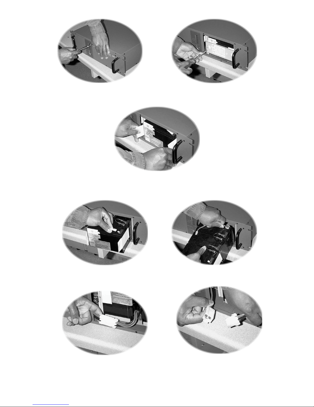
1. Using a Phillips (cross head) screwdriver loosen the (4) screws around the
battery door as in Figure 1. Carefully remove the battery door by pulling it
forward. Lay the battery door and screws aside for reassembly.
2. Again using a Phillips (cross head) screwdriver loosen the (4) screws holding
the battery retaining plate as in Figure 2. Carefully remove the battery
retaining plate by pulling it forward. Lay the battery retaining plate and screws
aside for reassembly.
3. 700/1000/1400 VA models: Gently pull on the white tabs located on both
sides of the battery until wiring is exposed (Figure 3). Disconnect red wire (+)
(figure 4) and the black wire (-) (figure 5).
2200 VA model: Pull apart the Battery harness connector (Figure 6 & 7).
Remove batteries.
4. Unpack new batteries taking care not to destroy the packing.
5. Slide new batteries into the cavity, noting the white pull-tabs are facing
outward.
6. For 700/1000/1400 VA models: Connect the battery wires; first black to black,
then red to red. For 2200 VA models: Connect the battery harness
connector. Push batteries back into cavity.
NOTE: There will be a small spark when connecting the Red to Red
connectors on 700-1400 VA models, and on the 2200 VA model when
connecting the battery harness connector. This is normal and will not harm
you or the UPS.
7. Replace the Battery retaining plate by inserting the (4) screws into their
associated holes. Tighten the (4) screws to secure the battery retaining plate
in place.
8. Replace the Battery door by inserting the four (4) screws into their associated
holes. Tighten the four (4) screws to secure the battery door in place.
9. Dispose of batteries in accordance with your local laws and regulations.
Page 18
18
Figure 3
Figure 5
Figure 4
Figure 1
Figure 2
Figure 6
Figure 7
Page 19
19
TROUBLESHOOTING
The information below indicates various symptoms a user may encounter in the
event the PowerSure™ Interactive UPS develops a problem. Use this information
to determine whether external factors cause the problem and how to remedy the
situation.
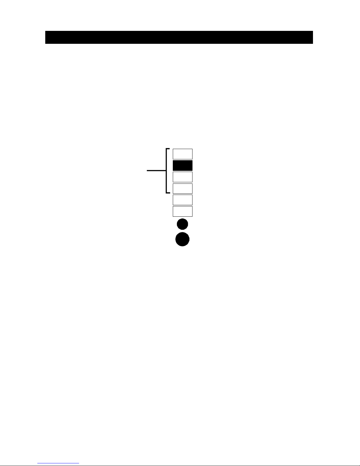
1. The fault indicator will flash every second to indicate the UPS detected a
problem.
2. An alarm will sound, alerting that the UPS requires attention.
3. One or more additional load/battery level LED segments will be illuminated to
provide a diagnostic aid to the operator, as described below:
A. UPS fault (fan failure, battery overcharge)
NOTE: The internal fan operates intermittently as needed
B. UPS failed battery test
D. UPS shutdown due to output overload time-out
A&B. UPS shutdown due to main input relay failure/output short circuit
A&D. UPS shutdown due to over temperature condition
B&D. UPS shutdown due to command from communication ports
(remote shutdown or SNMP)
The fault indicators will be illuminated indefinitely while battery charger is
operational, or for a maximum of 5 minutes while battery charger is not operational.
If a problem persists consult your dealer, or contact Liebert Technical Support
(LTS). World Wide Technical Support numbers are located at the end of this
section.
Load/ Battery
Level Indicators
Utility High/Low
Utility
Alarm silence/Test
On/Off
“D” indicator
Fault indicator
(flashes every second
)
“B” indicator
“A” indicator
Page 20

20
TROUBLESHOOTING GUIDE
PROBLEM CAUSE SOLUTION
UPS output short circuited or
overloaded.
Ensure UPS is off. Disconnect all
loads and ensure nothing is
lodged in output receptacles.
Ensure loads are not defective or
shorted internally.
UPS fails to start when On/Off
button is pressed
Internal fuse is blown, indicating
internal fault.
Do not attempt to open or service
the UPS. Contact your dealer or
LTS.
UPS not plugged in. UPS is operating in battery mode,
make certain UPS is securely
plugged into the wall receptacle.
UPS input protection has opened. UPS is operating in battery mode.
Save data and close applications.
Replace UPS input fuse or reset
input breaker, then restart UPS .
Utility indicator flashing
Utility voltage out of UPS input
range.
UPS is operating in battery mode.
Save data and close applications.
Ensure utility supply voltage is
within acceptable limits for UPS.
Batteries not charged. Keep UPS plugged in
continuously at least 24 hours to
recharge batteries.
UPS is overloaded. Check load level display and
remove non essential loads.
UPS has reduced battery time
Batteries may not be able to hold
a full charge due to age.
Replace batteries. Contact your
dealer or LTS for replacement
battery kit.
“Fault” indicator and diagnostic
LED “A” are illuminated
UPS fan failure or battery
overcharge.
UPS requires service. Contact
your dealer or LTS.
“Fault” indicator and diagnostic
LED “B” are illuminated
UPS failed the battery test. Replace batteries. Contact your
dealer or LTS for replacement
battery kit.
UPS shut down. “Fault” indicator
and diagnostic LED “D” are
illuminated
UPS overloaded or load
equipment is faulty.
Check load level display and
remove non essential loads.
Recalculate load VA and reduce
number of loads connected to
UPS. Check load equipment for
faults.
UPS shuts down with the “Fault”
indicator and diagnostic LEDs “A”
& “B” are illuminated
UPS shutdown due to internal
failure.
UPS requires service. Contact
your dealer or LTS.
UPS shuts down with the “Fault”
indicator and diagnostic LEDs “A”
& “D” are illuminated
UPS shutdown due to an internal
over temperature condition.
Ensure UPS is not overloaded,
ventilation openings not blocked,
or room ambient temperature not
excessive. Wait 30 minutes to
allow UPS to cool, then restart
UPS. If it does not restart,
contact your dealer or LTS.
UPS shuts down with the “Fault”
indicator and diagnostic LEDs “B”
& “D” are illuminated
UPS shutdown due to a command
from the communications port(s).
Your UPS has received a signal
or command from the attached
computer. If this was inadvertent,
ensure the communication cable
used is correct for your system.
For assistance, contact your
dealer or LTS.
Page 21
21
POWERSURE™ INTERACTIVE
TYPICAL BATTERY DISCHARGE CURVES
(Discharge times are at 25° C ambient)
0 25 50 75 100
0
20
40
60
80
Percent Load
R
un
Ti
me
(Mi
ns
)
0 25 50 75 100
0
20
40
60
80
Percent Load
Run Time (Mins)
0 25 50 75 100
0
20
40
60
80
P
ercent Load
R
un
Ti
me
(Mi
ns
)
0 25 50 75 100
0
20
40
60
80
P
ercent Load
Run Time (Mins)
700 VA 1000 VA
1400 VA 2200 VA
Page 22
22
AUDIBLE ALARM CONDITIONS
CONDITION ALARM
Battery mode
(utility failure)
One short beep every ten seconds; more than two
minutes of run time remaining
Low battery Two short beeps every five seconds; less than two
minutes of run time remaining
Battery replacement Two second beep every minute
UPS output overload One short beep every second
UPS fault Continuous tone
FUSE REPLACEMENT PROCEDURES
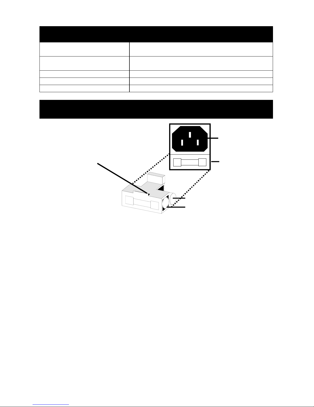
FOR 700 VA MODELS
CAUTION: Before changing the supply fuse, turn off the UPS, and unplug the
input cord from the AC input power supply and from the UPS.
1. Remove the fuse holder by inserting a flat blade screwdriver into the slot and
pulling out as indicated in the figure above.
2. Remove the input fuse.
3. Remove the spare fuse from its position by using the screwdriver to push it out.
4. Place spare fuse in the input fuse position, and replace the fuse holder. The
fuse holder will lock into position.
5. Reconnect the input power lead to the UPS, and the input power lead to the
input AC supply.
6. Restart the UPS. The UPS is ready for normal operation.
NOTE: For 1000, 1400, and 2200 VA units press the reset circuit protector button.
Insert flat blade screw
driver into slot and pull
fuse holder out to remove
AC Inlet
Fuse Holde
r
Input Fuse
Spare Fuse
Page 23

23
MINI-TOWER SPECIFICATIONS
Model Number PS700MT-120 PS1000MT-120 PS1400MT-120 PS2200MT-120
Model Rating VA/W 700 / 450 1000 / 670 1400 / 950 2200 / 1600
DIMENSIONS: in (mm)
Unit
W x D x H
5.5 x 14.4 x 7.0
(140 x 365 x 178)
6.8 x 17.5 x 8.9
(172 x 447 x 227)
6.8 x 17.5 x 8.9
(172 x 447 x 227)
7.6 x 20.1 x 13.2
(194 x 511 x 336)
Shipping
W x D x H
10.5 x 19.2 x 11.75
(265 x 492 x 300)
12.0 x 22.25 x 14
(307 x 581 x 358)
12.0 x 22.25 x 14
(307 x 581 x 358)
13.0 x 25.0 x 18.5
(330 x 635 x 470)
WEIGHT: lbs (kg)
Unit 29.9 (13.6) 43.4 (19.7) 49.4 (22.5) 81.7 (37.1)
Shipping 33.1 (15.0) 46.5 (21.1) 52.5 (23.9) 87.0 (39.5)
INPUT AC PARAMETERS
Voltage Range 120 VAC; -25%, +23%
Voltage Raise Maintains output to 120 VAC; -14%, when input is 120 VAC, -25%
Voltage Lower Maintains output to 120 VAC; +10%, when input is 120 VAC, +23%
Frequency 45-55 Hz or 55-65 Hz; auto sensing
Input
Power Cord
6 ft. detachable, w/
NEMA 5-15 P
6 ft. attached, w/
NEMA 5-15 P
6 ft. attached, w/
NEMA 5-15 P
6 ft. attached, w/
NEMA L5-30 P
OUTPUT AC PARAMETERS
Output Receptacles (4) 5-15R (6) 5-15R (6) 5-15R
(6)5-15R (2)5-20R
Voltage 103 VAC to 132 VAC
Max. Current Rating 5.8 A 8.3 A 11.67 A 18.3 A
Frequency 50 Hz or 60 Hz
Waveform Sinewave
Utility Mode Overload 200% for > 2 cycles; 110% for > 5 minutes
Battery Mode Overload 150% for > 1 cycle; 110% for > 30 seconds
BATTERY PARAMETERS
Type Valve-regulated, nonspillable, lead acid
Qty. x Voltage x Rating
2 x 12V x 7.0 or 7.2 AH 3 x 12V x 7.0 or 7.2 AH 4 x 12V x 7.0 or 7.2 AH 8 x 6V x 12 AH
Batt. Mfg./ Part Number CSB: GP1270F2 or Panasonic LC-R127R2CH1
Panasonic:
LC-R0612CH1
Transfer Time 2-6 ms typical
Back-up Time See Typical Battery Discharge Curves
3 Hours 3 Hours 5 Hours 3 HoursRecharge Time
to 95% capacity, after full discharge into 100% load
ENVIRONMENTAL
Operating Temperature +32° F to + 104° F (0° C to +40° C)
Storage Temperature +5° F to + 122° F (-15° C to +50° C)
Relative Humidity 0% to 95%, non-condensing
Operating Elevation Up to 10,000 ft. (3000 m) at 35° C without derating
Storage Elevation 50,000 ft. (15,000 m) maximum
Audible Noise <45 dBA, at 1 meter
AGENCY
Safety UL 1778, c-UL Listed
RFI/EMI FCC Part 15, Subpart B, Class A
Immunity IEC 801-2, Level 4 / IEC 801-4, Level 4 / IEEE 587 Category A
Page 24

24
RACKMOUNT SPECIFICATIONS
Model Number
PS700RM-120 PS1000RM-120 PS1400RM-120 PS2200RM-120
Model Rating VA/W 700 / 450 1000 / 670 1400 / 950 2200 / 1600
DIMENSIONS: in (mm)
Unit
W x D x H
19 x 18 x 5.25
(483 x 457 x 133)
19 x 18 x 5.25
(483 x 457 x 133)
19 x 18 x 5.25
(483 x 457 x 133)
19 x 18 x 7
(483 x 457 x 178)
Shipping
W x D x H
27.5 x 24 x 11
(699 x 610 x 279)
27.5 x 24 x 11
(699 x 610 x 279)
27.5 x 24 x 11
(699 x 610 x 279)
27.5 x 24 x 12
(699 x 610 x 305)
WEIGHT: lbs (kg)
Unit 41.5 (18.9) 51.29 (23.3) 57.2 (26.0) 86.0 (39.1)
Shipping 50.82 (23.1) 59.85 (27.2) 66.1 (30.0) 95.3 (43.3)
INPUT AC PARAMETERS
Voltage Range 120 VAC; -25%, +23%
Voltage Raise Maintains output to 120 VAC; -14%, when input is 120 VAC, -25%
Voltage Lower Maintains output to 120 VAC; +10%, when input is 120 VAC, +23%
Frequency 45-55 Hz or 55-65 Hz; auto sensing
Input
Power Cord
6 ft. detachable, w/
NEMA 5-15 P
6 ft. attached, w/
NEMA 5-15 P
6 ft. attached, w/
NEMA 5-15 P
6 ft. attached, w/
NEMA L5-30 P
OUTPUT AC PARAMETERS
Output Receptacles (6) 5-15R (6) 5-15R (6) 5-15R
(6)5-15R (2)5-20R
Voltage 103 VAC to 132 VAC
Max. Current Rating 5.8 A 8.3 A 11.67 A 18.3 A
Frequency 50 Hz or 60 Hz
Waveform Sinewave
Utility Mode Overload 200% for > 2 cycles; 110% for > 5 minutes
Battery Mode Overload 150% for > 1 cycle; 110% for > 30 seconds
BATTERY PARAMETERS
Type Valve-regulated, nonspillable, lead acid
Qty. x Voltage x Rating
2 x 12V x 7.0 or 7.2 AH 3 x 12V x 7.0 or 7.2 AH 4 x 12V x 7.0 or 7.2 AH 8 x 6V x 12 AH
Batt. Mfg./ Part Number CSB: GP1270F2 or Panasonic LC-R127R2CH1
Panasonic:
LC-R0612CH1
Transfer Time 2-6 ms typical
Back-up Time See Typical Battery Discharge Curves
3 Hours 3 Hours 5 Hours 3 HoursRecharge Time
to 95% capacity, after full discharge into 100% load
ENVIRONMENTAL
Operating Temperature +32° F to + 104° F (0° C to +40° C)
Storage Temperature +5° F to + 122° F (-15° C to +50° C)
Relative Humidity 0% to 95%, non-condensing
Operating Elevation Up to 10,000 ft. (3000 m) at 35° C without derating
Storage Elevation 50,000 ft. (15,000 m) maximum
Audible Noise <45 dBA, at 1 meter
AGENCY
Safety UL 1778, c-UL Listed
RFI/EMI FCC Part 15, Subpart B, Class A
Immunity IEC 801-2, Level 4 / IEC 801-4, Level 4 / IEEE 587 Category A
Page 25

25
Page 26
1050 Dearborn Drive Columbus, OH 43229 614-888-0246
Technical Support
U.S.A...............................................................1-800-222-5877
Outside the U.S.A ...........................................614-841-6755
U.K................................................................ +44 (0) 1793 553355
France ...........................................................+33 1 4 87 51 52
Germany ...................................................... +49 89 99 19 220
Italy .............................................................. +39 2 98250 1
Netherlands.................................................. +00 31 475 503333
Internet.......................................................... [email protected]
Web site ....................................................…
http://www.liebert.com
Worldwide FAX Tech Support......................…614-841-5471
The Company Behind The Products
With more than 500,000 installations around the
globe, Liebert is the world leader in computer
protection systems. Since its founding in 1965,
Liebert has developed a complete range of
support and protection systems for sensitive
electronics:
• Environmental systems: close-control air
conditioning from 1.5 to 60 tons.
• Power conditioning and UPS with power
ranges from 250 VA to more than 1000
kVA.
• Integrated systems that provide both
environmental and power protection in a
single, flexible package.
• Monitoring and control — on-site or
remote — from systems of any size or
location
Service and support, through more than 100
service centers around the world, and a 24-hour
Customer Response Center.
R
700-2200 VA
120 V
PowerSure™ Interactive
While every precaution has
been taken to ensure
Corporation assumes no
responsibility, and disclaims all
liability for damages resulting
from use of this information or
for any errors or omissions.
©1998 Liebert Corporation All
rights reserved throughout the
world. Specifications subject to
change without notice.
® Liebert and the Liebert logo
are registered trademarks of
Liebert Corporation. All names
referred to are trademarks or
registered trademarks of their
respective owners.
SL-23550 (2/98) Rev. 5.0
 Loading...