

Page 1
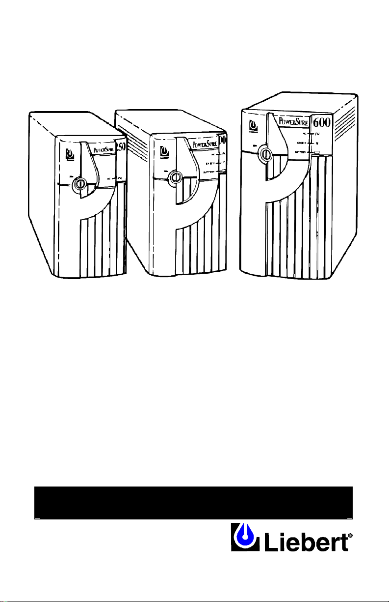
PowerSure™
R
250 VA
400 VA
600 VA
PS250-60S
PS400-60S
PS600-60S
POWER PROTECTION
Uninterruptible
Power System
250 VA – 600 VA
115 V
USER’S MANUAL
English
Page 2

2
IMPORTANT SAFETY INSTRUCTIONS
WARNING: Do not attempt to service this product yourself except to
replace the battery. Opening or removing the cover may expose you to
dangerous voltages, even when the AC cord is disconnected from the
electrical outlet. Refer all servicing to qualified service personnel.
1. SAVE THESE INSTRUCTIONS. ADHERE TO ALL OPERATING
INSTRUCTIONS AND WARNINGS ON THE UNIT AND IN THIS MANUAL.
CONSERVER CES INSTRUCTIONS. CETTE NOTICE CONTIENT DES INSTRUCTIONS
IMPORTANTES CONCERNANT LA SÉCURITÉ.
2. Liebert Corporation neither recommends nor knowingly sells this product for
use with life support or other U.S. FDA designated “critical” devices.
3. CAUTION: A BATTERY PRESENTS A RISK OF ELECTRICAL SHOCK OR
BURN FROM HIGH SHORT CIRCUIT CURRENT. OBSERVE PROPER
PRECAUTIONS.
ATTENTION: UNE BATTERIE PEUT PRÉSENTER UN RiSQUE DE CHOC ÉLECTRIQUEÉ DE
BRULURE PAR TRANSFERT D'ÉNERGIE. SUIVRE LES PRÉCATIONS QUI S'IMPOSENT.
4. WARNING: To reduce risk of fire or electric shock, install in a temperature
and humidity controlled area free from conductive contaminants.
AVERTISSEMENT: POUR RÉDUIRE LE RISQUE D'INCENDLE OU DE CHOC ÉLECTRIQUEÉ,
INSTALLE DANS UN SECTEUR AVEC TEMPÉRATURE CONTROLÉ ET HUMIDITÉ
CONTROLÉE EXAMPT DE POLLUANTS CONDUCTEURS.
5. Operate the UPS indoors only. Protect it from moisture and install it in a
clean environment, free from flammable liquids, gases, or corrosive
substances.
6. WARNING: Do not modify cable. Consult dealer if connector does not
match equipment. UPS must be grounded at all times while in use. Turn
UPS OFF before unplugging, or the safety ground from UPS to equipment
will be removed
7. CAUTION: Output receptacles on the UPS are electrically live if the UPS is
ON, even if the UPS is not plugged in. The on/off switch on the UPS does
not electrically isolate the internal parts. To isolate the UPS, unplug it.
8. CAUTION: Ground leakage current must not exceed 2.75 milli-amperes.
Most data processing equipment meets this requirement if you use no more
than 4 pieces of equipment. Note: These instructions may be modified by
local wiring regulations.
9. Unplug the UPS and turn the power switch OFF before cleaning. Use only
water dampened cloth, never liquid or aerosol cleaners.
10. Do not plug appliances, such as hair dryers or heaters into UPS receptacles.
11. Operate the UPS only from a grounded outlet (2 wire plus ground) 120 VAC,
60 Hz.
12. The UPS is equipped with a grounded NEMA 5-15 input power plug. Do not
defeat the safety purpose of this plug. If unable to fully insert the plug into
the outlet, contact an electrician.
13. Route power supply cords so they are not walked on or pinched.
14. Never block or insert any object into ventilation holes or other openings.
Maintain a minimum clearance of four inches all around the UPS for proper
airflow and cooling.
15. Always turn OFF the UPS and unplug it before opening battery door. To
replace batteries, refer to battery replacement procedure. If you feel
Page 3

3
unqualified to replace the battery, do not open battery door. Refer to
qualified service personnel.
INTRODUCTION & SYSTEM DESCRIPTION
Congratulations on choosing the Liebert PowerSure™. It provides continuous,
conditioned power to microcomputers and other data processing equipment.
Upon generation, AC power is clean and stable. However, during transmission, it
may be subject to load variations or accidents which cause power problems like
low voltage, voltage spikes, or complete power failure. These problems may
interrupt computer operations, cause data loss, or even damage equipment.
The UPS provides protection from many of these disturbances. It smoothes out
voltage variations and, in the event of complete power failure, it supports
equipment long enough for an orderly shutdown. These compact UPS units are
available in three ratings: 250, 400, and 600 VA. This manual includes
specifications for each model.
Normally, the UPS filters and connects AC utility input power to its AC outputs;
but when the UPS senses a power failure, it lights the battery LED (400 & 600
VA only) and provides AC power to equipment through a maintenance free,
sealed, lead acid battery.
The UPS contains a counter which automatically initiates a 15-second battery
test every 7 days and upon start-up. The UPS resets the counter after back-up
operation, manual battery test, or if the UPS is switched OFF. The operator may
perform a manual battery test by pressing the BATTERY TEST button on the
back of 400 and 600 VA models.
A control circuit monitors power input and battery condition and upon sensing a
fault, sounds an alarm and flashes a visual indication of the UPS status. In
addition, the 400VA and 600VA UPS models have a communications port which
enables the UPS to inform a computer equipped with SiteNet® software of the
power failure. SiteNet® automatically saves data and performs an orderly
shutdown. Cables and software are available as optional computer/LAN
Interface Kits. Consult your dealer for the kit suitable for your application.
CONDITIONS OF USE: The utility receptacle must be within 6 feet of the UPS.
This model utilizes a 110V to 120V AC 60 Hz supply voltage. Models are
available for other supply voltages.
Your UPS is designed to protect only Communication and Data Processing
equipment. Maximum load must not exceed that shown on UPS rating label. If
uncertain, consult your dealer or representative.
Placing magnetic storage media on top of the UPS may result in data corruption.
CAUTION: This equipment complies with Part 15, Subpart B of FCC rules for
Class B computing devices. Equipment operation in residential areas may cause
interference to radio and TV reception. The operator must take necessary steps
to correct interference.
Page 4
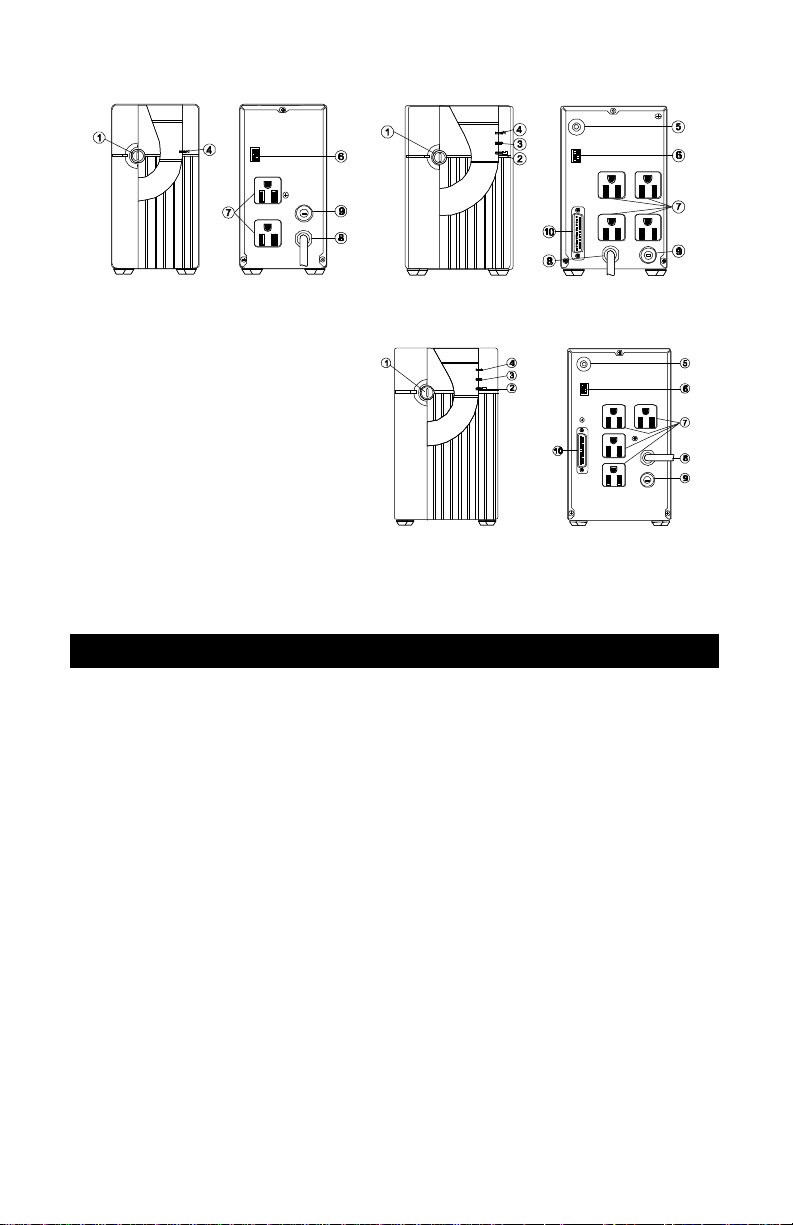
4
250 VA / 115 V
400 VA / 115 V
600 VA / 115 V
1. ON/OFF Button
2. Battery Light (400/600 Only)
3. Check Light (400/600 Only)
4. AC Light
5. Battery Test Button / Alarm Silence
(400/600 Only)
6. Option Switches
7. Output Receptacles
8. Power Cord Input
9. Circuit Breaker
10. Communications Port (400/600 Only)
ATTENTION: Please refer to these drawings when reading this
manual. This manual references the various parts of your UPS by
number.
GENERAL INSTALLATION
1. Unpack the unit and check the contents. There should be one UPS with
power cord (8) and one User’s Manual.
2. Check the items for damage. If any appear faulty or damaged, contact your
dealer immediately. Store the packaging in a safe place for possible future
shipment of UPS.
3. Place the UPS on a sturdy, dry surface in a well ventilated area away from
direct heat sources. Leave at least 4 inch (100 cm) clearance all around the
UPS to provide adequate ventilation.
4. Plug in the UPS and turn the UPS control switch (1) to ON.
5. Plugging in the UPS charges the batteries. Charge the UPS batteries for 12
hours before connecting the load equipment.
6. After charging the UPS, shut down your computer and unplug it. Plug the
computer equipment into the UPS AC outputs (7).
7. When all equipment is plugged in, the UPS is ready for normal operation.
Page 5
5
OPERATING INSTRUCTIONS
1. Check that all power connections to and from the unit are secure and fitted
with
the correct cables.
2. Press the UPS ON/OFF Button (1) to ON.
3. Switch your equipment ON at their respective power switch(es).
4. Check the condition of the UPS front panel LED's. The 250VA AC LED (4)
should be lit. For the 400/600 VA models, the AC LED (4) should be lit, and
the Check and Battery LED's (3 & 2) should be unlit.
5. Check the operation of your equipment. It should display normal operational
conditions.
6. If any function provides an abnormal condition, refer to the troubleshooting
guide later in this manual. If a problem persists, consult your dealer or call
Tech Support at 1-800-222-5877.
STARTING FROM BATTERY (400/600 VA only): Turn OFF UPS. Press and
hold BATTERY TEST button (5) for 4 seconds. Switch ON UPS and release
BATTERY TEST button (5). UPS will run in backup mode with the Battery LED
(2) lit. To stop, switch OFF at front panel.
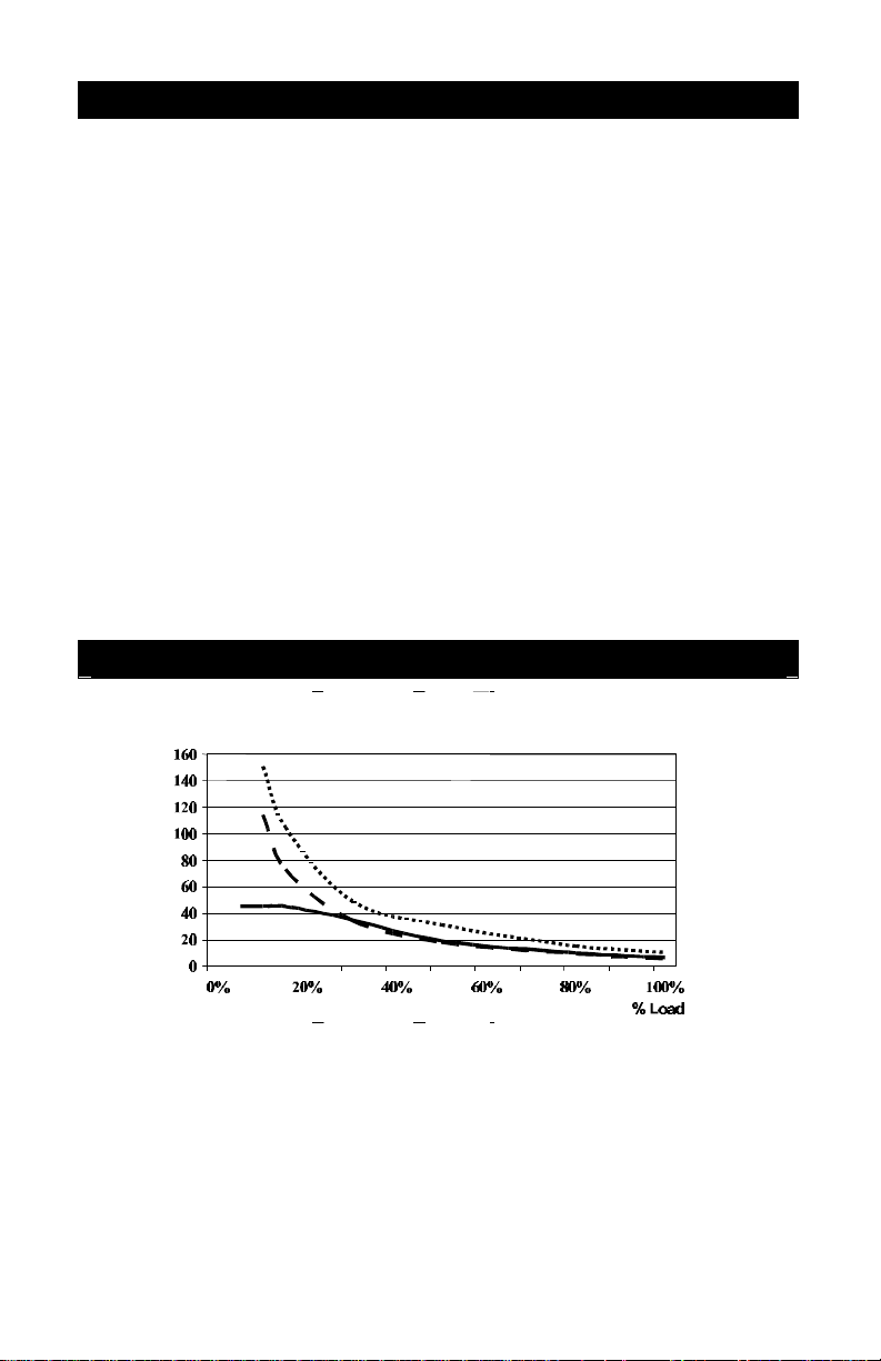
Battery Back-up Time
Back-up Time (minutes)
600 VA Models
400 VA Models
250 VA Models
Page 6
6
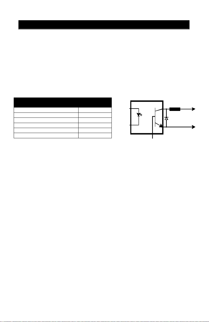
Maximum voltage and current on pins
1
COMPUTER/LAN INTERFACE (400/600 VA ONLY)
Optional SiteNet® 1 kits provide connection to a wide range of popular computer
operating systems such as Novell, UNIX, UNISYS, SUN, WINDOWS and many
others. SiteNet® 1 software automatically performs an orderly shutdown of
computer operating systems in the event of a power outage and/or low battery
conditions.
The SiteNet ®1 kit supplies a cable to connect supported computer systems to
the UPS communications port (10). The table below shows connector details.
Note: Your dealer supplies computer communications kits separately, if you wish. They
come with installation instructions, cable connections, and appropriate computer software.
INTERFACE FUNCTION DB25
ADAPTER
UPS Shutdown/Active High* 19
On Battery/Return 17
On Battery/Normally Open 16
Low Battery/Normally Open 11
Low Battery/Return 9
UPS Shutdown/Return 7
*Remote Shutdown (5-12V DC, 5-10 mA. max.); battery
operation
COLLECTOR TO EMITTER
Open Collector
330 Ohms
1
11 & 16 are +40V DC; 1.0mA
Return
(+)
(-)
Page 7

7
250 VA MODEL
400/600 VA MODELS
OPTION SWITCH SETTINGS
On the back of your UPS is a bank of option switches (6) with a removable
plastic cover. These switches determine transfer levels and operating frequency.
Slide the switches to the left to turn them OFF, to the right to turn ON. Turn OFF
equipment and UPS and unplug the UPS prior to changing switch settings, or the
UPS will ignore the new settings. Replace the plastic option switch cover.
Option Switch 1: 50/60 Hz Select – When OFF, this switch sets UPS for 60 Hz
utility. Output in backup mode will be 60 Hz. When ON, the switch sets UPS for
50 Hz utility and output in backup mode is 50 Hz. The switch must match the
utility frequency or the UPS will not start. The factory setting is 60 Hz.
Option Switch 2: High Line Transfer –
250VA model: When ON, this switch transfers the UPS to battery operation
when the utility voltage reaches 135 VAC. When OFF, the UPS will not
transfer to battery. Factory setting is ON.
400/600VA models: You may select at which voltage the UPS will transfer
to battery operation when it encounters a high utility voltage. The ON
position transfers the UPS to battery operation at 135VAC; the OFF position
transfers at 140VAC. Factory setting is 135 VAC.
Option Switch 3 & 4: Low Voltage Transfer Select – Low voltage transfer is
the voltage level at which battery operation starts. You may set the low voltage
transfer of the UPS to 90V, 95V, or 100V. The factory setting is 95V. This option
reduces excessive battery usage in brownout conditions. Make sure your
computer equipment can operate at 90 VAC before selecting the lowest limit
(most will). Refer to the tables below to change switch settings:
VOLTAGE SWITCH #3 SWITCH #4
100V ON N/A
95V OFF OFF
90V OFF ON
VOLTAGE SWITCH #3 SWITCH #4
100V OFF N/A
95V ON OFF
90V ON ON
Option Switch 5: Line Neutral Reverse Alarm – When ON, this switch enables
the L-N reverse alarm, which detects wiring faults. When OFF, the alarm is
disabled. The factory setting is ON.
BATTERY TEST BUTTON
The Battery Test Button (5) on the 400 and 600 VA models tests the condition of
the battery. If the charge is sufficient, the UPS lights the Battery Light (2), runs
on battery power for 15 seconds, then returns to utility power. If the battery fails
the test, the Check Light (3) illuminates and the UPS immediately returns to utility
power. The Check Light remains lit while on utility power. A battery in
unacceptable condition requires recharge or replacement of the battery.
Pressing the Battery Test Button (5) also silences alarms.
Page 8
8
BATTERY CARE AND USE
STORAGE: If the unit is not in continued use, plug in the UPS every 4 to 6
months for 12 hours to recharge the battery. Warranty is void if the battery
discharges below the minimum battery cutoff point. To prevent such discharge,
DO NOT leave UPS ON for more than two days without plugging it in.
BATTERY LIFE & REPLACEMENT: Excessive battery use, storage at high
ambient temperatures, and lengthy periods in a discharged state greatly reduce
battery life. Your UPS maximizes battery life by limiting the depth of battery
discharge. You may replace the UPS battery yourself, but if you feel unqualified,
refer battery replacement to qualified personnel. Contact your local dealer or call
Liebert for a replacement battery.
WARNING: To replace batteries, turn OFF UPS and unplug it from utility supply.
CAUTION: Observe proper precautions. When replacing batteries, use the
same number and type of batteries. Proper battery disposal required. Refer to
local codes for disposal requirements. DO NOT OPEN OR MUTILATE
BATTERY. RELEASED ELECTROLYTE IS HARMFUL TO SKIN AND EYES
AND IS TOXIC.
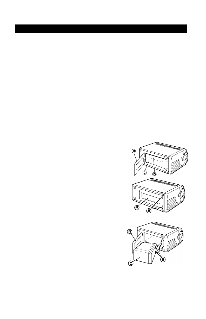
To Replace the Battery:
1. Close active programs and turn off
computers. Turn OFF the UPS and
unplug it from utility supply.
2. Place UPS on its side and remove retaining
screws (A) to battery door (B).
3. Open battery door (B) and remove the
battery (C) by pulling on the battery tab (D).
4. Remove terminal wires (E) from old battery.
Connect terminal wires (E) to new battery
(C); the red connects to the positive
terminal, the black connects to the
negative. DO NOT reverse terminal
connections. Slide battery (C) into unit, and
close battery door (B). Dispose of used
battery properly (it contains lead and acid).
5. Plug in UPS, turn it on, and charge
batteries for 8 to 10 hours.
Page 9

9
RESETTING THE CIRCUIT BREAKER
If the UPS is overloaded, the circuit breaker (9) at the lower rear of the UPS
activates to protect the UPS. If the circuit breaker activates, its center bar will
extend. To reset the circuit breaker, simply push the bar back in. If the circuit
breaker activates often, ask your dealer to check the UPS sizing or call Tech
Support at 1-800-222-5877.
ALARM CONDITIONS
The 400 VA and 600 VA models sound alarms and flash visual indications at the
front panel LED's (2, 3, 4) whenever they sense a power failure, low battery
voltage (while on battery), an overload, or a utility overvoltage condition. The
250 VA model only sounds an alarm. Sometimes, a fault in your computer
equipment may cause an overload alarm. See following page for alarm
indications.
You may silence the On-Battery alarm on 400 VA and 600 VA models by
pressing the BATTERY TEST button (5), on the rear panel. You must turn off
your computer equipment and then turn off the UPS to silence an alarm on a 250
VA model.
Refer to the first table on the next page for recommended actions when alarms
occur. Check this table first before calling for assistance. It diagnoses and
solves common problems, and helps prevent potential problems.
PROBLEM CAUSE SOLUTION
UPS will not start Input voltage below
UPS starts on
battery, but will not
switch to utility
power.
(400 & 600 VA
only)
UPS shuts down. Overload/Short Circuit
threshold
Overload/Short Circuit
Input frequency mismatch with option switch
setting
Utility overvoltage
UPS not plugged in
Circuit breaker activated
Power not available at
utility receptacle
Low Battery
Sitenet 1 Shutdown
(400 & 600 VA only)
Wait until utility voltage rises to appropriate level.
Check circuit breaker at rear of UPS (9). If it is activated, reset it and restart
the UPS (See "Resetting Circuit Breaker'). If problem persists, disconnect
some of the equipment from UPS - the total wattage or all your equipment
may exceed the capacity of the UPS. If it still will not start, check your
computer equipment for short circuits. For further help, call your dealer.
Check Option Switch #1 on rear of UPS (6). Slide switch to left for OFF, to
right for ON. OFF = 60 Hz, ON = 50 Hz. The UPS frequency must match
the frequency of your input utility supply.
Utility voltage must be less than 135 VAC.
Plug in power cord securely.
Reset circuit breaker (see “Resetting Circuit Breaker”) and restart UPS.
Call a qualified electrician.
Check circuit breaker at rear of UPS (9). If it is activated, reset it and restart
the UPS (See "Resetting Circuit Breaker"). If problem persists, disconnect
some of the equipment from UPS - the total wattage of all your equipment
may exceed the capacity of the UPS. If it still will not start, check your
computer equipment for short circuits. For further help, call your dealer.
Turn OFF equipment and recharge UPS battery for at least 8 hours. If
problem persists, replace battery.
Consult the SiteNet 1 User Manual or contact your LAN administrator.
Page 10

10
250 VA LED & ALARM INDICATIONS
Condition Green AC
NORMAL/START UP
Start-Up Test Fail On after Beep Fast Beep for 15 Sec and then Off Operate*
Input Frequency Mismatch with
Option Switch Setting
Input Voltage Below Threshold
Overload/Short Circuit Off Continuous for 15 Sec and then Off Will Not Start
NORMAL MODE
Battery Test Fail On Fast Beep for 15 Sec and then Off Operate
Overload/Short Circuit Off Continuous for 15 Sec and then Off Shutdown
BACKUP MODE
Low Battery Alarm Off Fast Beep Warn of Shutdown
Low Battery Shutdown
Overload/Short Circuit
Utility Overvoltage
(transfer enabled)
*The UPS starts and repeats the battery test sequence every hour until the test is passed.
400/600 VA LED & ALARM INDICATIONS
Condition
NORMAL/START UP
Start-Up Test Fail Off Off On Continuous for 15
Input Frequency Mismatch
with Option Switch Setting
Overload/Short Circuit
Input Voltage Below
Threshold
NORMAL MODE
Battery Test Fail On Off On N/A Operate
Overpower On Off Flash Fast Beep Alarm Only
Overload/Short Circuit Off On for 15
Charger Fail On Off On Slow Beep Alarm Only
BACKUP MODE
Low Battery Alarm Off On On Fast Beep Operate
Low Battery Shutdown Off On* On* Continuous for 15
Utility Undervoltage Off On Off Slow Beep Operate
Utility Overvoltage Off On Flash Slow Beep Operate
Overload/Short Circuit
SiteNet 1 Shutdown
*If there is insufficient utility voltage, this indicator illuminates for 15 seconds then turns off to preserve the battery.
Light (4)
On after Beep Single Beep, then Off Operate
Off
On Off Operate
Off Slow Beep Operate
Off
Off
Green AC
Light (4)
On
Off
Off Off Flash Continuous for 15
Amber
Battery
Light (2)
Flash Once &
then Off
On for 15
Sec and
then Off
On Off Off Off Operate
Sec & then
Off
Off On Off Slow Beep Operate
Off On* Flash* Continuous for 15
Audible Alarm Status
Continuous
Continuous for 15 Sec and then Off
Slow Beep
Red
Warning
Light (3)
Off
Flash Continuous for 15
Audible Alarm
Single Beep and then
Off
Sec and then Off
Sec and then Off
Sec and then Off
Flash for 15
Sec & then
Off
Continuous for 15
Sec & then Off
Sec & then Off
Sec & then Off
Will Not Start
Shutdown
Operate
Status
Operate
Will Not Start
Will Not Start
Will Not Start
Shutdown
Shutdown
Shutdown
Page 11

11
FCC ID #
Model # / Stock #
Model Rating
Dimensions
Unit (W x D x H) 3.51 x 10.18 x 6.79 in
Shipping (W x D x H) 7.13 x 14.37 x 11.93 in
Weight
Unit 8.8 lb. (4 kg) 12.5 lb. (5.7 kg) 19.8 lb. (9 kg)
Shipping 10.1 lb. (4.6 kg) 15.4 lb. (7 kg) 23.1 lb.(10.5 kg)
AC Parameters
Receptacles (2) NEMA 5-15 (4) NEMA 5-15 (4) NEMA 5-15
Input Voltage Range 90-135 VAC, Single Phase, 2 Wire Plus Ground
Low Voltage Transfer Point 95 VAC, User Selectable to 90 or 100 VAC
High Voltage Transfer Point 135 VAC 135 VAC, User Selectable to 140 VAC
Input Frequency Range 47 – 53 Hz, 57 – 63 Hz
Output Voltage (on battery) 115 VAC, ± 5%
Output waveform (on battery) Stepped Sine Wave
Max. Output Current at 120 V 2.1 A 3.3A 5 A
Output Frequency 50 or 60 Hz, ±5%
Max. Overload Capacity 115% of Power Rating
Battery
Type Sealed, Valve-Regulated Lead Acid, Maintenance-Free
Qty x Voltage x Rating 1 x 12 V x 4.5 AH 1 x 12 V x 7 AH 2 x 12 V x 7 AH
Back-up Time 6 minutes at full load
Time from Low Battery Alarm
to Shutdown
Recharge Time 8 – 10 Hours to 90% Capacity
Battery Life 3 – 5 Years Typical
Transfer Time to/from Inverter 2 – 6 msec. Typical
Agency Approvals
Safety UL, C-UL Listed
EMI / RFI Meets FCC Part 15, Subpart B, Class B
Surge Protection Meets IEEE 587, Category A and B
MTBF (Bellcore Method) 100,000 Hours (Excluding Battery)
Environmental Standards
Operating Temperatures 50° F to +104° F (10° C to +40° C)
Storage Temperatures 0° F to +104° F (-20° C to +40° C)
Cooling Convection
Audible Noise Less than 40 dB @ 1 meter
Operating Elevation Up to 9,900 ft. (3,000 m)
Storage Elevation Up to 33,000 ft. (10,000 m)
N/A BHKAF400T-60 BKAF600T-60
PS250-60/PS250-60S PS400-60 / PS400-60S PS600-60 / PS600-60S
250 VA / 150 W 400 VA / 240 W 600 VA / 360 W
(90 x 262 x 175 mm)
(181 x 365 x 303 mm)
Approximately 2 Minutes, depending on load
(High Temperatures Reduce Battery Life)
4.25 x 10.18 x 7.02 in
(109 x 262 x 186 mm)
8.35 x 18.98 x 11.5 in
(212 x 482 x 292 mm)
4.84 x 10.18 x 8.15 in
(124 x 262 x 216 mm)
9.33 x 18.98 x 13.15 in
(237 x 482 x 334 mm)
SPECIFICATIONS
Page 12

12
LIMITED WARRANTY
Liebert Corporation extends the following LIMITED WARRANTY to the
he "Purchaser"): the
enclosed Uninterruptible Power System (UPS) and components are free from
defects in materials and workmanship under normal use, service, and
maintenance FOR A PERIOD OF TWO YEARS FROM THE DATE OF
iebert dealer or retailer. THE
FOREGOING WARRANTY IS THE ONLY WARRANTY GIVEN AND NO
OTHER WARANTY IS PROVIDED, EXPRESS OR IMPLIED, INCLUDING
WITHOUT LIMITATION, MERCHANTABILITY OR FITNESS FOR A
licable to
consumer products acquired by individuals and used for personal, family, or
household purposes (as distinguished from industrial or other purposes). Local
laws may not allow limitations on how long an implied warranty lasts, so the
ion may not apply to you. This warranty gives you specific legal
Certain repairs or services are the responsibility of the Purchaser and the
s warranty does not extend either to
products with removed or altered serial numbers or to any losses or damages
due to act of God or source external to the product, misuse, accident, abuse,
pair, use beyond
rated capacity, or improper installation, maintenance, application or use,
including, without limitation, use in a manner contrary to the accompanying
instructions or applicable codes. WARNING: Warranty is void if the battery is
discharge below the minimum battery cutoff point. To prevent such
discharge DO NOT leave the unit power switch "ON" for more than two (2) days
without AC power being supplied to the UPS. The battery must be recharged
If the UPS fails to conform with the above warranty within the two year warranty
period, Liebert will repair or replace the UPS, at Liebert's option. Repairs or
replacements are warranted for the remainder of the original warranty period.
5877 to obtain a
Returned Goods Authorization number and shipping instructions. Return
t recommended, and the Company will not knowingly sell this
product, for use with life support and other designated "critical" devices. ANY
SUCH USE BY A USER AUTOMATICALLY VOIDS AND DISCLAIMS ANY
AND ALL WARRANTIES, INCLUDING ANY IMPLIED WARRANTY OF
ANTABILITY, IMPLIED WARRANTY OF FITNESS FOR A
PARTICULAR PURPOSE, AND EXPRESS WARRANTIES THAT THIS
PRODUCT WILL CONFORM TO ANY AFFIRMATION OR PROMISE, FOR
THIS PRODUCT AND THE USER AGREES THAT IN NO EVENT SHALL THE
purchaser and to its customer (collectively referred to as t
ORIGINAL PURCHASE from Liebert or the L
PARTICULAR PURPOSE. Certain aspects of disclaimers are not app
above limitat
rights, and you may have other rights which vary according to local law.
Purchaser is expected to pay for them. Thi
neglect, negligence, unauthorized modification, alteration, or re
allowed to
every four (4) to six (6) months when not in use.
Purchaser, to make a warranty claim, should call 1-800-222transportation costs to Liebert are the responsibility of the Purchaser.
This product is no
MERCH
COMPANY BE LIABLE FOR CONSEQUENTIAL OR INDIRECT DAMAGES.
"LIFE SUPPORT" POLICY
Page 13

13
R
1050 Dearborn Drive Columbus, OH 43229 614-888-0246
Technical Support
U.S.A................................................................ 1-800-222-5877
Outside the U.S.A ........................................... 614-841-6755
U.K................................................................ +44 (0) 1793 553355
France ...........................................................+33 1 4 87 51 52
Germany ...................................................... +49 89 99 19 220
Italy .............................................................. +39 2 98250 1
Netherlands.................................................. +00 31 475 503333
Internet.......................................................... [email protected]
Web site ....................................................… http://www.liebert.com
Worldwide FAX tech support......................…614-841-5471
While every precaution has been taken to ensure
accuracy and completeness in this manual, Liebert
Corporation assumes no responsibility, and
disclaims all liability for damages resulting from
use of this information or for any errors or
omissions.
©1996 Liebert Corporation All rights reserved
throughout the world. Specifications subject to
change without notice.
® Liebert and the Liebert logo are registered
trademarks of Liebert Corporation. All names
referred to are trademarks or registered
trademarks of their respective owners.
Printed in U.S.A.
SL-23235 (11/97) Rev. 3.0
 Loading...