

Page 1
Precision Cooling
For Business-Critical Continuity™
Liebert® DS
User Manual
28-105kW, 8-30 Tons, Upflow and Downflow, 50/60Hz
™
Page 2

Page 3

TABLE OF CONTENTS
IMPORTANT SAFETY INSTRUCTIONS . . . . . . . . . . . . . . . . . . . . . . . . . . . . . . . . . . . . . . . . . . . . . . . . 1
SAVE THESE INSTRUCTIONS . . . . . . . . . . . . . . . . . . . . . . . . . . . . . . . . . . . . . . . . . . . . . . . . .1
1.0 LIEBERT DS COMPONENTS AND NOMENCLATURE . . . . . . . . . . . . . . . . . . . . . . . . . . . . . . . .3
2.0 COOLING CONFIGURATIONS . . . . . . . . . . . . . . . . . . . . . . . . . . . . . . . . . . . . . . . . . . . . . . . .6
3.0 PRE-INSTALLATION GUIDELINES . . . . . . . . . . . . . . . . . . . . . . . . . . . . . . . . . . . . . . . . . . . . .7
3.1 Room Preparation. . . . . . . . . . . . . . . . . . . . . . . . . . . . . . . . . . . . . . . . . . . . . . . . . . . . . . . . . . . . 7
3.2 Air Distribution—Downflow Units . . . . . . . . . . . . . . . . . . . . . . . . . . . . . . . . . . . . . . . . . . . . . . 7
3.3 Air Distribution—Upflow Units . . . . . . . . . . . . . . . . . . . . . . . . . . . . . . . . . . . . . . . . . . . . . . . . 8
3.4 Connections and System Setup . . . . . . . . . . . . . . . . . . . . . . . . . . . . . . . . . . . . . . . . . . . . . . . . . 9
3.5 Operating Conditions . . . . . . . . . . . . . . . . . . . . . . . . . . . . . . . . . . . . . . . . . . . . . . . . . . . . . . . . . 9
4.0 LIEBERT DS DIMENSIONS AND WEIGHTS. . . . . . . . . . . . . . . . . . . . . . . . . . . . . . . . . . . . . .10
5.0 EQUIPMENT INSPECTION AND HANDLING . . . . . . . . . . . . . . . . . . . . . . . . . . . . . . . . . . . . . .35
5.1 Packaging Material . . . . . . . . . . . . . . . . . . . . . . . . . . . . . . . . . . . . . . . . . . . . . . . . . . . . . . . . . 35
SAFETY INFORMATION . . . . . . . . . . . . . . . . . . . . . . . . . . . . . . . . . . . . . . . . . . . . . . . . . . . . .35
5.2 Unpacking the Unit . . . . . . . . . . . . . . . . . . . . . . . . . . . . . . . . . . . . . . . . . . . . . . . . . . . . . . . . . 36
5.2.1 Removing the Unit from the Skid With a Forklift . . . . . . . . . . . . . . . . . . . . . . . . . . . . . . . . . . 37
5.2.2 Moving the Unit to the Installation Location with Piano Jacks . . . . . . . . . . . . . . . . . . . . . . . 38
5.2.3 Removing Piano Jacks . . . . . . . . . . . . . . . . . . . . . . . . . . . . . . . . . . . . . . . . . . . . . . . . . . . . . . . . 38
5.2.4 Removing Liebert DS from Skid Using Rigging . . . . . . . . . . . . . . . . . . . . . . . . . . . . . . . . . . . . 39
5.3 Semi-Hermetic Compressor Spring Isolation System . . . . . . . . . . . . . . . . . . . . . . . . . . . . . . 41
5.4 Placing the Unit on a Floor Stand. . . . . . . . . . . . . . . . . . . . . . . . . . . . . . . . . . . . . . . . . . . . . . 41
6.0 DISASSEMBLING THE LIEBERT DS FOR TRANSPORT . . . . . . . . . . . . . . . . . . . . . . . . . . . . .42
6.1 Required Equipment . . . . . . . . . . . . . . . . . . . . . . . . . . . . . . . . . . . . . . . . . . . . . . . . . . . . . . . . 42
6.2 Disassembly—Downflow Units . . . . . . . . . . . . . . . . . . . . . . . . . . . . . . . . . . . . . . . . . . . . . . . . 42
6.2.1 Remove the Compressor Assembly . . . . . . . . . . . . . . . . . . . . . . . . . . . . . . . . . . . . . . . . . . . . . . 44
6.2.2 Remove the Filter and Electric Box Assembly . . . . . . . . . . . . . . . . . . . . . . . . . . . . . . . . . . . . . 44
6.3 Reassembly—Downflow Units. . . . . . . . . . . . . . . . . . . . . . . . . . . . . . . . . . . . . . . . . . . . . . . . . 45
6.3.1 Reconnecting Piping, Charging and Replacing Panels. . . . . . . . . . . . . . . . . . . . . . . . . . . . . . . 45
6.4 Reassembly Checklist. . . . . . . . . . . . . . . . . . . . . . . . . . . . . . . . . . . . . . . . . . . . . . . . . . . . . . . . 46
6.5 Disassembly—Upflow Units . . . . . . . . . . . . . . . . . . . . . . . . . . . . . . . . . . . . . . . . . . . . . . . . . . 56
6.5.1 Remove Compressor Assembly . . . . . . . . . . . . . . . . . . . . . . . . . . . . . . . . . . . . . . . . . . . . . . . . . 57
6.5.2 Remove Blower and Electric Box Assembly . . . . . . . . . . . . . . . . . . . . . . . . . . . . . . . . . . . . . . . 57
6.6 Reassembly—Upflow Unit . . . . . . . . . . . . . . . . . . . . . . . . . . . . . . . . . . . . . . . . . . . . . . . . . . . . 58
6.7 Reassembly Checklist. . . . . . . . . . . . . . . . . . . . . . . . . . . . . . . . . . . . . . . . . . . . . . . . . . . . . . . . 58
i
Page 4

7.0 ELECTRICAL CONNECTIONS . . . . . . . . . . . . . . . . . . . . . . . . . . . . . . . . . . . . . . . . . . . . . . .68
7.1 Electrical Field Connection Descriptions . . . . . . . . . . . . . . . . . . . . . . . . . . . . . . . . . . . . . . . . 70
8.0 PIPING . . . . . . . . . . . . . . . . . . . . . . . . . . . . . . . . . . . . . . . . . . . . . . . . . . . . . . . . . . . . . . .72
8.1 Fluid Connections. . . . . . . . . . . . . . . . . . . . . . . . . . . . . . . . . . . . . . . . . . . . . . . . . . . . . . . . . . . 72
8.1.1 Condensate Piping—Field-Installed . . . . . . . . . . . . . . . . . . . . . . . . . . . . . . . . . . . . . . . . . . . . . 72
8.1.2 Humidifier Supply Water—Optional Infrared . . . . . . . . . . . . . . . . . . . . . . . . . . . . . . . . . . . . . 74
8.1.3 Requirements of Systems Using Water or Glycol . . . . . . . . . . . . . . . . . . . . . . . . . . . . . . . . . . . 74
8.2 Refrigeration Piping . . . . . . . . . . . . . . . . . . . . . . . . . . . . . . . . . . . . . . . . . . . . . . . . . . . . . . . . . 75
8.2.1 Piping Guidelines—Air-Cooled Units . . . . . . . . . . . . . . . . . . . . . . . . . . . . . . . . . . . . . . . . . . . . 76
8.3 Dehydration/Leak Test and Charging Procedures for R-407C and R-22 . . . . . . . . . . . . . . . 78
8.3.1 Air-Cooled Condenser with Fan Speed Head Pressure Control System . . . . . . . . . . . . . . . . . 78
8.3.2 Air-Cooled Condenser with Lee-Temp “Flooded Condenser” Head Pressure Control System 80
9.0 PIPING SCHEMATICS. . . . . . . . . . . . . . . . . . . . . . . . . . . . . . . . . . . . . . . . . . . . . . . . . . . . .82
10.0 CHECKLIST FOR COMPLETED INSTALLATION . . . . . . . . . . . . . . . . . . . . . . . . . . . . . . . . . . 107
10.1 Moving and Placing Equipment . . . . . . . . . . . . . . . . . . . . . . . . . . . . . . . . . . . . . . . . . . . . . . 107
10.2 Electrical . . . . . . . . . . . . . . . . . . . . . . . . . . . . . . . . . . . . . . . . . . . . . . . . . . . . . . . . . . . . . . . . . 107
10.3 Piping . . . . . . . . . . . . . . . . . . . . . . . . . . . . . . . . . . . . . . . . . . . . . . . . . . . . . . . . . . . . . . . . . . . 107
10.4 Other . . . . . . . . . . . . . . . . . . . . . . . . . . . . . . . . . . . . . . . . . . . . . . . . . . . . . . . . . . . . . . . . . . . . 107
11.0 INITIAL STARTUP CHECKS AND COMMISSIONING PROCEDURE FOR WARRANTY INSPECTION . .
108
11.1 Information for Warranty Inspection—Remove Power From Unit Disconnect . . . . . . . . . 109
11.2 Startup Checks Inspection With Panels Removed and Disconnect Off. . . . . . . . . . . . . . . . 109
11.3 Commissioning Procedure With Panels On . . . . . . . . . . . . . . . . . . . . . . . . . . . . . . . . . . . . . 110
12.0 MAINTENANCE . . . . . . . . . . . . . . . . . . . . . . . . . . . . . . . . . . . . . . . . . . . . . . . . . . . . . . . . 111
12.1 Filters . . . . . . . . . . . . . . . . . . . . . . . . . . . . . . . . . . . . . . . . . . . . . . . . . . . . . . . . . . . . . . . . . . . 111
12.1.1 Filter Replacement Procedure—Downflow Units. . . . . . . . . . . . . . . . . . . . . . . . . . . . . . . . . . 112
12.1.2 Filter Replacement Procedure—Upflow Units . . . . . . . . . . . . . . . . . . . . . . . . . . . . . . . . . . . . 112
12.2 Blower Drive System . . . . . . . . . . . . . . . . . . . . . . . . . . . . . . . . . . . . . . . . . . . . . . . . . . . . . . . 112
12.2.1 Upflow Motor Access . . . . . . . . . . . . . . . . . . . . . . . . . . . . . . . . . . . . . . . . . . . . . . . . . . . . . . . . 113
12.2.2 Belt Removal. . . . . . . . . . . . . . . . . . . . . . . . . . . . . . . . . . . . . . . . . . . . . . . . . . . . . . . . . . . . . . . 113
12.2.3 Belt Installation and Tensioning . . . . . . . . . . . . . . . . . . . . . . . . . . . . . . . . . . . . . . . . . . . . . . . 113
12.3 Humidifier. . . . . . . . . . . . . . . . . . . . . . . . . . . . . . . . . . . . . . . . . . . . . . . . . . . . . . . . . . . . . . . . 115
12.3.1 Infrared Humidifier . . . . . . . . . . . . . . . . . . . . . . . . . . . . . . . . . . . . . . . . . . . . . . . . . . . . . . . . . 115
12.3.2 Cleaning Humidifier Pan and Float Switch . . . . . . . . . . . . . . . . . . . . . . . . . . . . . . . . . . . . . . 115
12.3.3 Changing Humidifier Lamps . . . . . . . . . . . . . . . . . . . . . . . . . . . . . . . . . . . . . . . . . . . . . . . . . . 116
12.4 Condensate Drain and Condensate Pump Systems . . . . . . . . . . . . . . . . . . . . . . . . . . . . . . . 116
12.4.1 Condensate Drain . . . . . . . . . . . . . . . . . . . . . . . . . . . . . . . . . . . . . . . . . . . . . . . . . . . . . . . . . . . 116
12.4.2 Condensate Pump . . . . . . . . . . . . . . . . . . . . . . . . . . . . . . . . . . . . . . . . . . . . . . . . . . . . . . . . . . 116
ii
Page 5

12.5 Air-Cooled Condenser and Drycoolers. . . . . . . . . . . . . . . . . . . . . . . . . . . . . . . . . . . . . . . . . . 117
12.6 Reheat—Electric Reheat (Three-Stage and SCR) . . . . . . . . . . . . . . . . . . . . . . . . . . . . . . . . 117
12.7 Compressor . . . . . . . . . . . . . . . . . . . . . . . . . . . . . . . . . . . . . . . . . . . . . . . . . . . . . . . . . . . . . . . 117
12.7.1 Compressor Oil . . . . . . . . . . . . . . . . . . . . . . . . . . . . . . . . . . . . . . . . . . . . . . . . . . . . . . . . . . . . . 117
12.7.2 Semi-Hermetic Compressors . . . . . . . . . . . . . . . . . . . . . . . . . . . . . . . . . . . . . . . . . . . . . . . . . . 117
12.7.3 Scroll and Digital Scroll Compressors . . . . . . . . . . . . . . . . . . . . . . . . . . . . . . . . . . . . . . . . . . . 117
12.8 Compressor Replacement. . . . . . . . . . . . . . . . . . . . . . . . . . . . . . . . . . . . . . . . . . . . . . . . . . . . 118
12.8.1 Compressor Motor Burnout . . . . . . . . . . . . . . . . . . . . . . . . . . . . . . . . . . . . . . . . . . . . . . . . . . . 118
12.8.2 Digital Compressor Unloading Solenoid(s) . . . . . . . . . . . . . . . . . . . . . . . . . . . . . . . . . . . . . . . 118
12.8.3 Compressor Replacement Procedure . . . . . . . . . . . . . . . . . . . . . . . . . . . . . . . . . . . . . . . . . . . . 118
12.9 Facility Fluid and Piping Maintenance. . . . . . . . . . . . . . . . . . . . . . . . . . . . . . . . . . . . . . . . . 118
12.10 Paradenser—Water-Cooled Condenser. . . . . . . . . . . . . . . . . . . . . . . . . . . . . . . . . . . . . . . . . 119
12.10.1 Cleaning Instructions. . . . . . . . . . . . . . . . . . . . . . . . . . . . . . . . . . . . . . . . . . . . . . . . . . . . . . . . 119
12.11 Water/Glycol Control Valves . . . . . . . . . . . . . . . . . . . . . . . . . . . . . . . . . . . . . . . . . . . . . . . . . 119
12.11.1 Regulating Valves – Semi Hermetic and Standard Scroll Compressors. . . . . . . . . . . . . . . . 119
12.11.2 Motor Ball Valve—Digital Scroll Compressors . . . . . . . . . . . . . . . . . . . . . . . . . . . . . . . . . . . . 120
12.11.3 Drycooler Settings . . . . . . . . . . . . . . . . . . . . . . . . . . . . . . . . . . . . . . . . . . . . . . . . . . . . . . . . . . 121
13.0 HVAC MAINTENANCE CHECKLIST. . . . . . . . . . . . . . . . . . . . . . . . . . . . . . . . . . . . . . . . . .122
iii
Page 6

FIGURES
Figure 1 Downflow model component locations . . . . . . . . . . . . . . . . . . . . . . . . . . . . . . . . . . . . . . . . . . . . . . . . 3
Figure 2 Upflow model component locations . . . . . . . . . . . . . . . . . . . . . . . . . . . . . . . . . . . . . . . . . . . . . . . . . . 4
Figure 3 Liebert DS model number nomenclature. . . . . . . . . . . . . . . . . . . . . . . . . . . . . . . . . . . . . . . . . . . . . . 5
Figure 4 Downflow unit ducting and plenum ducting . . . . . . . . . . . . . . . . . . . . . . . . . . . . . . . . . . . . . . . . . . . 7
Figure 5 Upflow ducting configurations . . . . . . . . . . . . . . . . . . . . . . . . . . . . . . . . . . . . . . . . . . . . . . . . . . . . . . 8
Figure 6 Cabinet and floor planning dimensions—downflow, air-cooled, 28-42kW (8-12 ton),
semi-hermetic compressor models . . . . . . . . . . . . . . . . . . . . . . . . . . . . . . . . . . . . . . . . . . . . . . . . . . 11
Figure 7 Cabinet and floor planning dimensions—downflow, air-cooled, 28-42kW (8-12 ton),
scroll compressor models . . . . . . . . . . . . . . . . . . . . . . . . . . . . . . . . . . . . . . . . . . . . . . . . . . . . . . . . . 12
Figure 8 Cabinet and floor planning dimensions—downflow, water/glycol/GLYCOOL,
28-42kW (8-12 ton), all compressor models . . . . . . . . . . . . . . . . . . . . . . . . . . . . . . . . . . . . . . . . . . 13
Figure 9 Cabinet and floor planning dimensions—downflow, air-cooled, 53-77kW (15-22 ton),
semi-hermetic compressor models . . . . . . . . . . . . . . . . . . . . . . . . . . . . . . . . . . . . . . . . . . . . . . . . . 14
Figure 10 Cabinet and floor planning dimensions—downflow, air-cooled, 53-77kW (15-22 ton),
scroll compressor models . . . . . . . . . . . . . . . . . . . . . . . . . . . . . . . . . . . . . . . . . . . . . . . . . . . . . . . . . 15
Figure 11 Cabinet and floor planning dimensions—downflow, water/glycol/GLYCOOL,
53-77kW (15-22 ton), all compressor models . . . . . . . . . . . . . . . . . . . . . . . . . . . . . . . . . . . . . . . . . 16
Figure 12 Cabinet and floor planning dimensions—downflow, air-cooled, 105kW (30 ton),
all compressor models . . . . . . . . . . . . . . . . . . . . . . . . . . . . . . . . . . . . . . . . . . . . . . . . . . . . . . . . . . . 17
Figure 13 Cabinet and floor planning dimensions—downflow, water/glycol/GLYCOOL, 105kW (30 ton),
all compressor models . . . . . . . . . . . . . . . . . . . . . . . . . . . . . . . . . . . . . . . . . . . . . . . . . . . . . . . . . . . 18
Figure 14 Cabinet and floor planning dimensions—upflow, air-cooled 28-42kW (8-12 ton),
semi-hermetic compressor models . . . . . . . . . . . . . . . . . . . . . . . . . . . . . . . . . . . . . . . . . . . . . . . . . 19
Figure 15 Cabinet and floor planning dimensions—upflow, air-cooled 28-42kW (8-12 ton),
scroll or digital scroll compressor models . . . . . . . . . . . . . . . . . . . . . . . . . . . . . . . . . . . . . . . . . . . . 20
Figure 16 Cabinet and floor planning dimensions—upflow, water/glycol/GLYCOOL,
28-42kW (8-12 ton), all compressor models . . . . . . . . . . . . . . . . . . . . . . . . . . . . . . . . . . . . . . . . . . 21
Figure 17 Cabinet and floor planning dimensions—upflow, air-cooled, 53-77kW (15-22 ton),
semi-hermetic compressor models . . . . . . . . . . . . . . . . . . . . . . . . . . . . . . . . . . . . . . . . . . . . . . . . . 22
Figure 18 Cabinet and floor planning dimensions—upflow, air-cooled, 53-77kW (15-22 ton),
scroll or digital scroll compressor models . . . . . . . . . . . . . . . . . . . . . . . . . . . . . . . . . . . . . . . . . . . . 23
Figure 19 Cabinet and floor planning dimensions—upflow, water/glycol/GLYCOOL,
53-77kW (15-22 ton), all compressor models . . . . . . . . . . . . . . . . . . . . . . . . . . . . . . . . . . . . . . . . . 24
Figure 20 Cabinet and floor planning dimensions—upflow, air-cooled, 105kW (30 ton), all . . . . . . . . . . . . 25
Figure 21 Cabinet and floor planning dimensions—upflow water/glycol/GLYCOOL 105kW (30 ton),
all compressors . . . . . . . . . . . . . . . . . . . . . . . . . . . . . . . . . . . . . . . . . . . . . . . . . . . . . . . . . . . . . . . . . 26
Figure 22 Floor stand dimensions—downflow, 28-42kW (8-12 ton) models. . . . . . . . . . . . . . . . . . . . . . . . . . 27
Figure 23 Floor stand dimensions—downflow, 53-77kW (15-22 ton) models. . . . . . . . . . . . . . . . . . . . . . . . . 28
Figure 24 Floor stand dimensions—downflow, 105kW (30 ton) models . . . . . . . . . . . . . . . . . . . . . . . . . . . . . 29
Figure 25 Blower outlet and deck dimensions—upflow, 28-42kW (8-12 ton). . . . . . . . . . . . . . . . . . . . . . . . . 30
Figure 26 Blower outlet and deck dimensions—upflow, 53-77kW (15-22 ton). . . . . . . . . . . . . . . . . . . . . . . . 31
Figure 27 Blower outlet and deck dimensions—upflow 105kW (30ton) . . . . . . . . . . . . . . . . . . . . . . . . . . . . . 32
Figure 28 Rear return filter box dimensions . . . . . . . . . . . . . . . . . . . . . . . . . . . . . . . . . . . . . . . . . . . . . . . . . . 33
Figure 29 Upflow unit plenum dimensions . . . . . . . . . . . . . . . . . . . . . . . . . . . . . . . . . . . . . . . . . . . . . . . . . . . 34
Figure 30 Equipment recommended for handling Liebert DS . . . . . . . . . . . . . . . . . . . . . . . . . . . . . . . . . . . . 36
Figure 31 Removing packaging . . . . . . . . . . . . . . . . . . . . . . . . . . . . . . . . . . . . . . . . . . . . . . . . . . . . . . . . . . . . . 36
Figure 32 Remove the unit from the skid . . . . . . . . . . . . . . . . . . . . . . . . . . . . . . . . . . . . . . . . . . . . . . . . . . . . . 37
Figure 33 Moving the unit to its installation location . . . . . . . . . . . . . . . . . . . . . . . . . . . . . . . . . . . . . . . . . . . 38
Figure 34 Locate center of gravity marker and place slings . . . . . . . . . . . . . . . . . . . . . . . . . . . . . . . . . . . . . . 39
Figure 35 Using rigging to lift Liebert DS off skid . . . . . . . . . . . . . . . . . . . . . . . . . . . . . . . . . . . . . . . . . . . . . 40
Figure 36 Setting the unit on a floor stand . . . . . . . . . . . . . . . . . . . . . . . . . . . . . . . . . . . . . . . . . . . . . . . . . . . 41
iv
Page 7

Figure 37 Component dimensions—downflow, air-cooled, 28-42kW (8-12 ton), semi-hermetic
compressor models . . . . . . . . . . . . . . . . . . . . . . . . . . . . . . . . . . . . . . . . . . . . . . . . . . . . . . . . . . . . . . 47
Figure 38 Component dimensions—downflow, air-cooled, 28-42kW (8-12 ton), scroll/digital scroll
compressor models . . . . . . . . . . . . . . . . . . . . . . . . . . . . . . . . . . . . . . . . . . . . . . . . . . . . . . . . . . . . . . 48
Figure 39 Component dimensions—downflow, water/glycol/GLYCOOL, 28-42kW (8-12 ton),
all compressor models . . . . . . . . . . . . . . . . . . . . . . . . . . . . . . . . . . . . . . . . . . . . . . . . . . . . . . . . . . . 49
Figure 40 Component dimensions—downflow, air-cooled, 53-77kW (15-22 ton), semi-hermetic
compressor models . . . . . . . . . . . . . . . . . . . . . . . . . . . . . . . . . . . . . . . . . . . . . . . . . . . . . . . . . . . . . . 50
Figure 41 Component dimensions—downflow air-cooled, 53-77kW (15-22 ton), scroll/digital
scroll compressor models . . . . . . . . . . . . . . . . . . . . . . . . . . . . . . . . . . . . . . . . . . . . . . . . . . . . . . . . . 51
Figure 42 Component dimensions—downflow water/glycol, GLYCOOL, 53-77kW (15-22 ton),
all compressor models . . . . . . . . . . . . . . . . . . . . . . . . . . . . . . . . . . . . . . . . . . . . . . . . . . . . . . . . . . . 52
Figure 43 Component dimensions—downflow, air-cooled, 105kW (30 ton), semi-hermetic compressor
models . . . . . . . . . . . . . . . . . . . . . . . . . . . . . . . . . . . . . . . . . . . . . . . . . . . . . . . . . . . . . . . . . . . . . . . . 53
Figure 44 Component dimensions—downflow, air-cooled, 105kW (30 ton), scroll compressor models . . . . 54
Figure 45 Component dimensions—downflow, water/glycol/GLYCOOL, 105kW (30 ton), all
compressor models . . . . . . . . . . . . . . . . . . . . . . . . . . . . . . . . . . . . . . . . . . . . . . . . . . . . . . . . . . . . . . 55
Figure 46 Component dimensions—upflow, air-cooled, 28-42kW (8-12 ton), semi-hermetic compressor
models . . . . . . . . . . . . . . . . . . . . . . . . . . . . . . . . . . . . . . . . . . . . . . . . . . . . . . . . . . . . . . . . . . . . . . . . 59
Figure 47 Component dimensions—upflow, air-cooled, 28-42kW (8-12 ton), scroll/digital scroll
compressor models . . . . . . . . . . . . . . . . . . . . . . . . . . . . . . . . . . . . . . . . . . . . . . . . . . . . . . . . . . . . . . 60
Figure 48 Component dimensions—upflow, water/glycol/GLYCOOL, 28-42kW (8-12 ton), all
compressor models . . . . . . . . . . . . . . . . . . . . . . . . . . . . . . . . . . . . . . . . . . . . . . . . . . . . . . . . . . . . . . 61
Figure 49 Component dimensions—upflow, air-cooled, 53-77kw (15-22 ton), semi-hermetic
compressor models . . . . . . . . . . . . . . . . . . . . . . . . . . . . . . . . . . . . . . . . . . . . . . . . . . . . . . . . . . . . . . 62
Figure 50 Component dimensions—upflow, air-cooled, 53-77kw (15-22 ton), scroll/digital scroll
compressor models . . . . . . . . . . . . . . . . . . . . . . . . . . . . . . . . . . . . . . . . . . . . . . . . . . . . . . . . . . . . . . 63
Figure 51 Component dimensions—upflow water/glycol/GLYCOOL 53-77kw (15-22 ton), all
compressor models . . . . . . . . . . . . . . . . . . . . . . . . . . . . . . . . . . . . . . . . . . . . . . . . . . . . . . . . . . . . . . 64
Figure 52 Component dimensions—upflow, air-cooled, 105kW (30 ton), semi-hermetic compressor
models . . . . . . . . . . . . . . . . . . . . . . . . . . . . . . . . . . . . . . . . . . . . . . . . . . . . . . . . . . . . . . . . . . . . . . . . 65
Figure 53 Component dimensions—upflow, air-cooled, 105kW (30 ton), scroll/digital scroll
compressor models . . . . . . . . . . . . . . . . . . . . . . . . . . . . . . . . . . . . . . . . . . . . . . . . . . . . . . . . . . . . . . 66
Figure 54 Component dimensions—upflow, water/glycol/GLYCOOL, 105kW (30 ton), all
compressor models . . . . . . . . . . . . . . . . . . . . . . . . . . . . . . . . . . . . . . . . . . . . . . . . . . . . . . . . . . . . . . 67
Figure 55 Electrical field connections . . . . . . . . . . . . . . . . . . . . . . . . . . . . . . . . . . . . . . . . . . . . . . . . . . . . . . . . 69
Figure 56 Gravity drain for downflow and upflow units . . . . . . . . . . . . . . . . . . . . . . . . . . . . . . . . . . . . . . . . . 73
Figure 57 Piping schematic—air-cooled, semi-hermetic compressor models . . . . . . . . . . . . . . . . . . . . . . . . . 82
Figure 58 Piping schematic—air-cooled, scroll compressor models . . . . . . . . . . . . . . . . . . . . . . . . . . . . . . . . 83
Figure 59 Piping schematic—water/glycol, semi-hermetic compressor models . . . . . . . . . . . . . . . . . . . . . . . 84
Figure 60 Piping schematic—water/glycol with scroll compressor models. . . . . . . . . . . . . . . . . . . . . . . . . . . 85
Figure 61 Piping schematic—GLYCOOL semi-hermetic compressor models . . . . . . . . . . . . . . . . . . . . . . . . 86
Figure 62 Piping schematic—GLYCOOL with scroll compressor models . . . . . . . . . . . . . . . . . . . . . . . . . . . 87
Figure 63 Piping schematic—water/glycol with digital scroll compressor models . . . . . . . . . . . . . . . . . . . . . 88
Figure 64 GLYCOOL with digital scroll compressor models. . . . . . . . . . . . . . . . . . . . . . . . . . . . . . . . . . . . . . 89
Figure 65 Optional piping schematic for Econ-O-Coil . . . . . . . . . . . . . . . . . . . . . . . . . . . . . . . . . . . . . . . . . . . 90
Figure 66 Primary connection locations—downflow, air-cooled, 28-42kW (8-12 ton), semi-hermetic
compressor models . . . . . . . . . . . . . . . . . . . . . . . . . . . . . . . . . . . . . . . . . . . . . . . . . . . . . . . . . . . . . . 91
Figure 67 Primary connection locations—downflow, air-Cooled, 28-42kW (8-12 ton) with scroll
compressor models . . . . . . . . . . . . . . . . . . . . . . . . . . . . . . . . . . . . . . . . . . . . . . . . . . . . . . . . . . . . . . 92
Figure 68 Primary connection locations—downflow water/glycol/GLYCOOL 28-42kW (8-12 ton),
all compressor models . . . . . . . . . . . . . . . . . . . . . . . . . . . . . . . . . . . . . . . . . . . . . . . . . . . . . . . . . . . . 93
Figure 69 Primary connection locations—downflow, air-Cooled, 53-77kW (15-22 ton), semi-hermetic
compressor models . . . . . . . . . . . . . . . . . . . . . . . . . . . . . . . . . . . . . . . . . . . . . . . . . . . . . . . . . . . . . . 94
v
Page 8

Figure 70 Primary connection locations—downflow, air-Cooled, 53-77kW (15-22 ton) with scroll
compressor models . . . . . . . . . . . . . . . . . . . . . . . . . . . . . . . . . . . . . . . . . . . . . . . . . . . . . . . . . . . . . . 95
Figure 71 Primary connection locations—downflow, water/glycol/GLYCOO,L 53-77kW (15-22 ton),
all compressor models . . . . . . . . . . . . . . . . . . . . . . . . . . . . . . . . . . . . . . . . . . . . . . . . . . . . . . . . . . . 96
Figure 72 Primary connection locations—downflow, air-cooled, 105kW (30 ton), all compressor models . . 97
Figure 73 Primary connection locations—downflow, air-cooled, 105kW (30 ton), all compressor models . . 98
Figure 74 Primary connection locations—upflow, air-cooled, 28-42kw (8-12 ton), semi-hermetic
compressor models . . . . . . . . . . . . . . . . . . . . . . . . . . . . . . . . . . . . . . . . . . . . . . . . . . . . . . . . . . . . . . 99
Figure 75 Primary connection locations—upflow, air-Cooled, 28-42kW (8-12 ton), semi-hermetic
compressor models . . . . . . . . . . . . . . . . . . . . . . . . . . . . . . . . . . . . . . . . . . . . . . . . . . . . . . . . . . . . . 100
Figure 76 Primary connection locations—upflow, water/glycol/GLYCOOL, 28-42kW (8-12 ton),
all compressor models . . . . . . . . . . . . . . . . . . . . . . . . . . . . . . . . . . . . . . . . . . . . . . . . . . . . . . . . . . 101
Figure 77 Primary connection locations—upflow, air-cooled, 53-77kW (15-22 ton), semi-hermetic
compressor models . . . . . . . . . . . . . . . . . . . . . . . . . . . . . . . . . . . . . . . . . . . . . . . . . . . . . . . . . . . . . 102
Figure 78 Primary connection locations—upflow, air-cooled, 53-77kW (15-22 ton), scroll compressor
models . . . . . . . . . . . . . . . . . . . . . . . . . . . . . . . . . . . . . . . . . . . . . . . . . . . . . . . . . . . . . . . . . . . . . . . 103
Figure 79 Primary connection locations—upflow, water/glycol/GLYCOOL, 53-77kW (15-22 ton),
all compressor models . . . . . . . . . . . . . . . . . . . . . . . . . . . . . . . . . . . . . . . . . . . . . . . . . . . . . . . . . . . 104
Figure 80 Primary connection locations—upflow, air-cooled, 105kW (30 ton), all. . . . . . . . . . . . . . . . . . . . 105
Figure 81 Primary connection locations—upflow, water/glycol/GLYCOOL, 105kW (30 ton), all . . . . . . . . 106
Figure 82 Proper filter pleat direction . . . . . . . . . . . . . . . . . . . . . . . . . . . . . . . . . . . . . . . . . . . . . . . . . . . . . . 112
Figure 83 Upflow motor access . . . . . . . . . . . . . . . . . . . . . . . . . . . . . . . . . . . . . . . . . . . . . . . . . . . . . . . . . . . . 113
Figure 84 Auto-belt tensioning motor base . . . . . . . . . . . . . . . . . . . . . . . . . . . . . . . . . . . . . . . . . . . . . . . . . . 114
Figure 85 Correct orientation of float switch . . . . . . . . . . . . . . . . . . . . . . . . . . . . . . . . . . . . . . . . . . . . . . . . . 115
vi
Page 9

TABLES
Table 1 Shipping dimensions—domestic and export, inches (mm) . . . . . . . . . . . . . . . . . . . . . . . . . . . . . . . 10
Table 2 Shipping weights—approximate, kg . . . . . . . . . . . . . . . . . . . . . . . . . . . . . . . . . . . . . . . . . . . . . . . . 10
Table 3 Weights for downflow, air-cooled, 28-42kW (8-12 ton), semi-hermetic compressor models . . . . . 11
Table 4 Weights for downflow, air-cooled, 28-42kW (8-12 ton), scroll compressor models . . . . . . . . . . . . 12
Table 5 Weights for downflow, water/glycol/GLYCOOL, 28-42kW (8-12 ton), all compressor models . . . 13
Table 6 Weights for downflow, air-cooled, 53-77kW (15-22 ton), semi-hermetic compressor models . . . . 14
Table 7 Weights for downflow, air-cooled, 53-77kW (15-22 ton), scroll compressor models . . . . . . . . . . . 15
Table 8 Weights for downflow, water/glycol/GLYCOOL, 53-77kW (15-22 ton), all compressor models . . 16
Table 9 Weights for downflow, air-Cooled, 105kW (30 ton), all compressor models . . . . . . . . . . . . . . . . . 17
Table 10 Weights for downflow, water/glycol/GLYCOOL, 105kW (30 ton), all compressor models . . . . . . 18
Table 11 Weight for upflow, air-cooled, 28-42kW (8-12 ton), semi-hermetic compressor models . . . . . . . . 19
Table 12 Weight for upflow, air-cooled, 28-42kW (8-12 ton), scroll or digital scroll compressor models . . 20
Table 13 Weights for upflow, water/glycol/GLYCOOL, 28-42kW (8-12 ton), all compressor models . . . . . 21
Table 14 Weights for upflow, air-cooled, 53-77kW (15-22 ton), semi-hermetic compressor models . . . . . . 22
Table 15 Weight for upflow, air-cooled, 53-77kW (15-22 ton), scroll or digital scroll compressor models . 23
Table 16 Weights for upflow, water/glycol/GLYCOOL, 53-77kW (15-22 ton), all compressor models . . . . 24
Table 17 Weights—upflow, air-cooled, 105kW (30 ton), all . . . . . . . . . . . . . . . . . . . . . . . . . . . . . . . . . . . . . . 25
Table 18 Weights—upflow water/glycol/GLYCOOL 105kW (30 ton), all compressors. . . . . . . . . . . . . . . . . 26
Table 19 Floor stand and floor planning dimensions—downflow, 28-42kW (8-12 ton) models . . . . . . . . . . 27
Table 20 Floor stand and floor planning dimensions—downflow, 53-77kW (15-22 ton) models . . . . . . . . . 28
Table 21 Floor stand and floor planning dimensions—downflow, 105kW (30 ton) models . . . . . . . . . . . . . 29
Table 22 Dimensions for upflow, 28-42kW (8-12 ton) . . . . . . . . . . . . . . . . . . . . . . . . . . . . . . . . . . . . . . . . . . 30
Table 23 Blower outlet and deck dimensions for upflow, 53-77kW (15-22 ton) . . . . . . . . . . . . . . . . . . . . . . 31
Table 24 Blower outlet and deck dimensions—upflow 105kW (30ton) . . . . . . . . . . . . . . . . . . . . . . . . . . . . . 32
Table 25 Rear return filter box dimensions . . . . . . . . . . . . . . . . . . . . . . . . . . . . . . . . . . . . . . . . . . . . . . . . . . 33
Table 26 Upflow unit plenum dimensions . . . . . . . . . . . . . . . . . . . . . . . . . . . . . . . . . . . . . . . . . . . . . . . . . . . 34
Table 27 Component weights—downflow, air-cooled, 28-42kW (8-12 ton), semi-hermetic . . . . . . . . . . . . . 47
Table 28 Component weights—downflow, air-cooled, 28-42kW (8-12 ton), scroll/digital scroll. . . . . . . . . . 48
Table 29 Component weights—downflow, water/glycol/GLYCOOL, 28-42kW (8-12 ton), all . . . . . . . . . . . 49
Table 30 Component weights—downflow, air-cooled, 53-77kW (15-22 ton), semi-hermetic . . . . . . . . . . . . 50
Table 31 Component weights—downflow, air-cooled, 53-77kW (15-22 ton), scroll/digital scroll. . . . . . . . . 51
Table 32 Component weights—downflow water/glycol, GLYCOOL, 53-77kW (15-22 ton), all . . . . . . . . . . 52
Table 33 Component weights—downflow, air-cooled, 105kW (30 ton), semi-hermetic compressors. . . . . . 53
Table 34 Component weights—downflow, air-cooled, 105kW (30 ton), scroll compressor models . . . . . . . 54
Table 35 Component weights—downflow, water/glycol/GLYCOOL, 105kW (30 ton), all compressor
models . . . . . . . . . . . . . . . . . . . . . . . . . . . . . . . . . . . . . . . . . . . . . . . . . . . . . . . . . . . . . . . . . . . . . . . . 55
Table 36 Component weights—upflow, air-cooled, 28-42kW (8-12 ton), semi-hermetic compressor
models . . . . . . . . . . . . . . . . . . . . . . . . . . . . . . . . . . . . . . . . . . . . . . . . . . . . . . . . . . . . . . . . . . . . . . . . 59
Table 37 Component weights—upflow, air-cooled, 28-42kW (8-12 ton), scroll/digital scroll compressor
models . . . . . . . . . . . . . . . . . . . . . . . . . . . . . . . . . . . . . . . . . . . . . . . . . . . . . . . . . . . . . . . . . . . . . . . . 60
Table 38 Component weights—upflow, water/glycol/GLYCOOL, 28-42kW (8-12 ton), all compressor
models . . . . . . . . . . . . . . . . . . . . . . . . . . . . . . . . . . . . . . . . . . . . . . . . . . . . . . . . . . . . . . . . . . . . . . . . 61
Table 39 Component weights—upflow air-cooled 53-77kw (15-22 ton), semi-hermetic compressor
models . . . . . . . . . . . . . . . . . . . . . . . . . . . . . . . . . . . . . . . . . . . . . . . . . . . . . . . . . . . . . . . . . . . . . . . . 62
Table 40 Component weights—upflow, air-cooled, 53-77kw (15-22 ton), scroll /digital scroll
compressor models . . . . . . . . . . . . . . . . . . . . . . . . . . . . . . . . . . . . . . . . . . . . . . . . . . . . . . . . . . . . . . 63
Table 41 Component weights—upflow water/glycol/GLYCOOL, 53-77kW (15-22 ton) all compressor
models . . . . . . . . . . . . . . . . . . . . . . . . . . . . . . . . . . . . . . . . . . . . . . . . . . . . . . . . . . . . . . . . . . . . . . . . 64
Table 42 Component weights—upflow, air-cooled, 105kW (30 ton), semi-hermetic compressor models . . 65
vii
Page 10

Table 43 Component weights—upflow, air-cooled, 105kW (30 ton), scroll/digital scroll compressor
models . . . . . . . . . . . . . . . . . . . . . . . . . . . . . . . . . . . . . . . . . . . . . . . . . . . . . . . . . . . . . . . . . . . . . . . . 66
Table 44 Component weights—upflow, water/glycol/GLYCOOL, 105kW (30 ton), all compressor
models . . . . . . . . . . . . . . . . . . . . . . . . . . . . . . . . . . . . . . . . . . . . . . . . . . . . . . . . . . . . . . . . . . . . . . . . 67
Table 45 Recommended refrigerant line sizes - OD copper (inches)* . . . . . . . . . . . . . . . . . . . . . . . . . . . . . . 76
Table 46 Indoor unit approximate refrigerant charge for R-22 or R-407C . . . . . . . . . . . . . . . . . . . . . . . . . . 76
Table 47 Line charges - refrigerant per 100 ft (30m) of Type “L” copper tube . . . . . . . . . . . . . . . . . . . . . . . 77
Table 48 Outdoor condenser approximate refrigerant charge lb (kg) per circuit . . . . . . . . . . . . . . . . . . . . . 77
Table 49 Fan speed suction pressure transducer settings . . . . . . . . . . . . . . . . . . . . . . . . . . . . . . . . . . . . . . . 79
Table 50 Lee-Temp suction pressure transducer settings . . . . . . . . . . . . . . . . . . . . . . . . . . . . . . . . . . . . . . . 81
Table 51 Piping data—upflow, air-cooled 105kW (30 ton), all. . . . . . . . . . . . . . . . . . . . . . . . . . . . . . . . . . . 105
Table 52 Piping data—upflow, upflow, water/glycol/GLYCOOL, 105kW (30 ton), all . . . . . . . . . . . . . . . . 106
Table 53 Filter quantities, downflow units . . . . . . . . . . . . . . . . . . . . . . . . . . . . . . . . . . . . . . . . . . . . . . . . . . 111
Table 54 Filter quantities, upflow units . . . . . . . . . . . . . . . . . . . . . . . . . . . . . . . . . . . . . . . . . . . . . . . . . . . . 111
Table 55 Compressor oil types . . . . . . . . . . . . . . . . . . . . . . . . . . . . . . . . . . . . . . . . . . . . . . . . . . . . . . . . . . . . 117
Table 56 Recommended refrigerant pressures . . . . . . . . . . . . . . . . . . . . . . . . . . . . . . . . . . . . . . . . . . . . . . . 119
Table 57 Water/glycol system conditions requiring optional settings for aquastats . . . . . . . . . . . . . . . . . 121
Table 58 Aquastat settings—two-fan through four-fan drycoolers . . . . . . . . . . . . . . . . . . . . . . . . . . . . . . . 121
Table 59 Aquastat settings—six-fan drycoolers . . . . . . . . . . . . . . . . . . . . . . . . . . . . . . . . . . . . . . . . . . . . . . 121
Table 60 Aquastat settings—eight-fan drycoolers . . . . . . . . . . . . . . . . . . . . . . . . . . . . . . . . . . . . . . . . . . . . 121
viii
Page 11
IMPORTANT SAFETY INSTRUCTIONS
SAVE THESE INSTRUCTIONS
This manual contains important safety instructions that should be followed during the installation
and maintenance of the Liebert DS
operate this unit.
Only qualified personnel should move, install or service this equipment.
Adhere to all warnings, cautions and installation, operating and safety instructions on the unit and in
this manual. Follow all operating and user instructions.
WARNING
!
Risk of electric shock. Can cause injury or death.
Disconnect local and remote power supplies before working within.
Before proceeding with installation, read all instructions, verify that all the parts are included
and check the nameplate to be sure the voltage matches available utility power.
The iCOM microprocessor does not isolate power from the unit, even in the “unit off” mode.
Some internal components require and receive power even during the “unit off” mode of iCOM
control.
The factory-supplied optional disconnect switch is inside the unit. The line side of this switch
contains live high-voltage.
The only way to ensure that there is NO voltage inside the unit is to install and open a remote
disconnect switch. Refer to unit electrical schematic.
Follow all local codes.
WARNING
!
Risk of explosive discharge from high-pressure refrigerant. Can cause injury or death.
This unit contains fluids and gases under high pressure. Relieve pressure before working with
piping.
™
. Read this manual thoroughly before attempting to install or
WARNING
!
Risk of refrigerant system rupture or explosion from overpressurization. Can cause
equipment damage, injury or death.
If a pressure relief device is not provided with the condenser unit, the system installer must
provide and install a discharge pressure relief valve rated for a maximum of 500 psig (34bar)
in the high side refrigerant circuit. Do not install a shutoff valve between the compressor and
the field installed relief valve.
One or more additional pressure relief valves are required downstream of any and all fieldinstalled isolation valves as shown in Figures 57 and 58. Do not isolate any refrigerant
circuits from overpressurization protection.
For systems requiring EU CE compliance (50Hz), the pressure relief valve must be CE
certified to the EU Pressure Equipment Directive by an EU “Notified Body.”
NOTE
A pressure relief valve is provided with Liebert Lee-Temp
provided on Liebert Fan Speed Control condensers. The Liebert indoor cooling unit has a
factory-installed high pressure safety switch in the high side refrigerant circuit.
™
condensers. A fusible plug is
1
Page 12
WARNING
!
Risk of high-speed moving parts. Can cause injury or death.
Disconnect all local and remote electric power supplies before working in the unit.
Do not operate upflow units without installing a plenum, ductwork or guard over the blower
opening(s) on the top surface of the unit cabinet.
Ductwork must be connected to the blower(s), or a plenum must be installed on the blower
deck for protection from rotating blower wheel(s) on upflow units.
CAUTION
!
Risk of contact with hot surfaces. Can cause injury.
The compressors, refrigerant discharge lines, humidifiers and reheats are extremely hot
during unit operation. Allow sufficient time for them to cool before working within the unit
cabinet. Use extreme caution and wear protective gloves and arm protection when working on
or near hot compressors, discharge lines, humidifiers and reheats.
CAUTION
!
Risk of leaking water. Can cause equipment and building damage.
This unit requires a water drain connection. It may also require an external water supply to
operate.
Improper installation, application and service practice can result in water leakage from the
unit. Water leakage can result in severe property damage and loss of critical data center
equipment.
Do not locate unit directly above any equipment that could sustain water damage.
Emerson recommends installing leak detection equipment for unit and supply lines.
2
Page 13
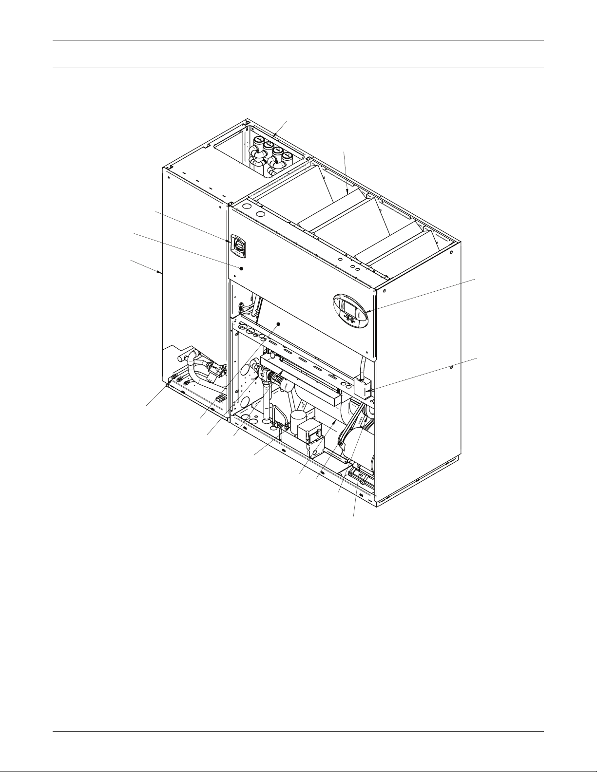
1.0 LIEBERT DS COMPONENTS AND NOMENCLATURE
Figure 1 Downflow model component locations
14
3
11
2
9
Liebert DS Components and Nomenclature
1
15
4
16
1. iCOM Control Display
2. Electric Box
3. Filters
4. Evaporator Coil
5. Motor
6. Blower
7. Fan Pulley
8. Motor Sheave and Belts
9. Compressor Section
10
12
6
8
7
5
10. Infrared Humidifier, optional
11. Disconnect, optional
12. Condensate Pump, optional
13. Smoke Sensor, optional
14. Condenser Cleanout Plugs,
fluid-cooled units only
15.Condenser Drain Plugs,
fluid-cooled units only
16. Econ-O-Coil Valve, GLYCOOL/Dual Cooling
13
DPN000958
Rev. 1
3
Page 14
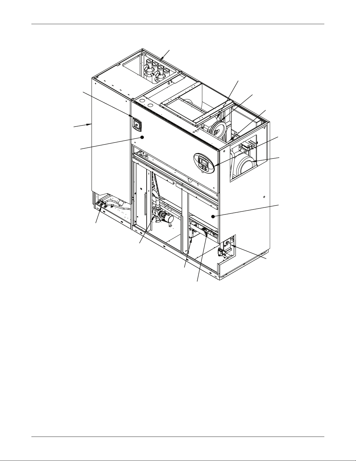
Figure 2 Upflow model component locations
Liebert DS Components and Nomenclature
14
6
11
7
8
9
1
2
5
4
15
16
1. iCom Control Display
2. Electric Box
3. Filters
4. Evaporator Coil
5. Motor
6. Blower
7. Fan Pulley
8. Motor Sheave and Belts
13
12
10
9. Compressor Section
DPN001222
Rev. 0
10. Infrared Humidifier (optional)
11. Disconnect (optional)
12. Condensate Pump (optional)
13. Smoke Sensor (optional)
14. Condenser Cleanout Plugs (fluid cooled units only)
15. Condenser Drain Plugs ( fluid cooled units only)
16. Econ-O-Coil Valve (GLYCOOL/Dual Cooling)
4
Page 15
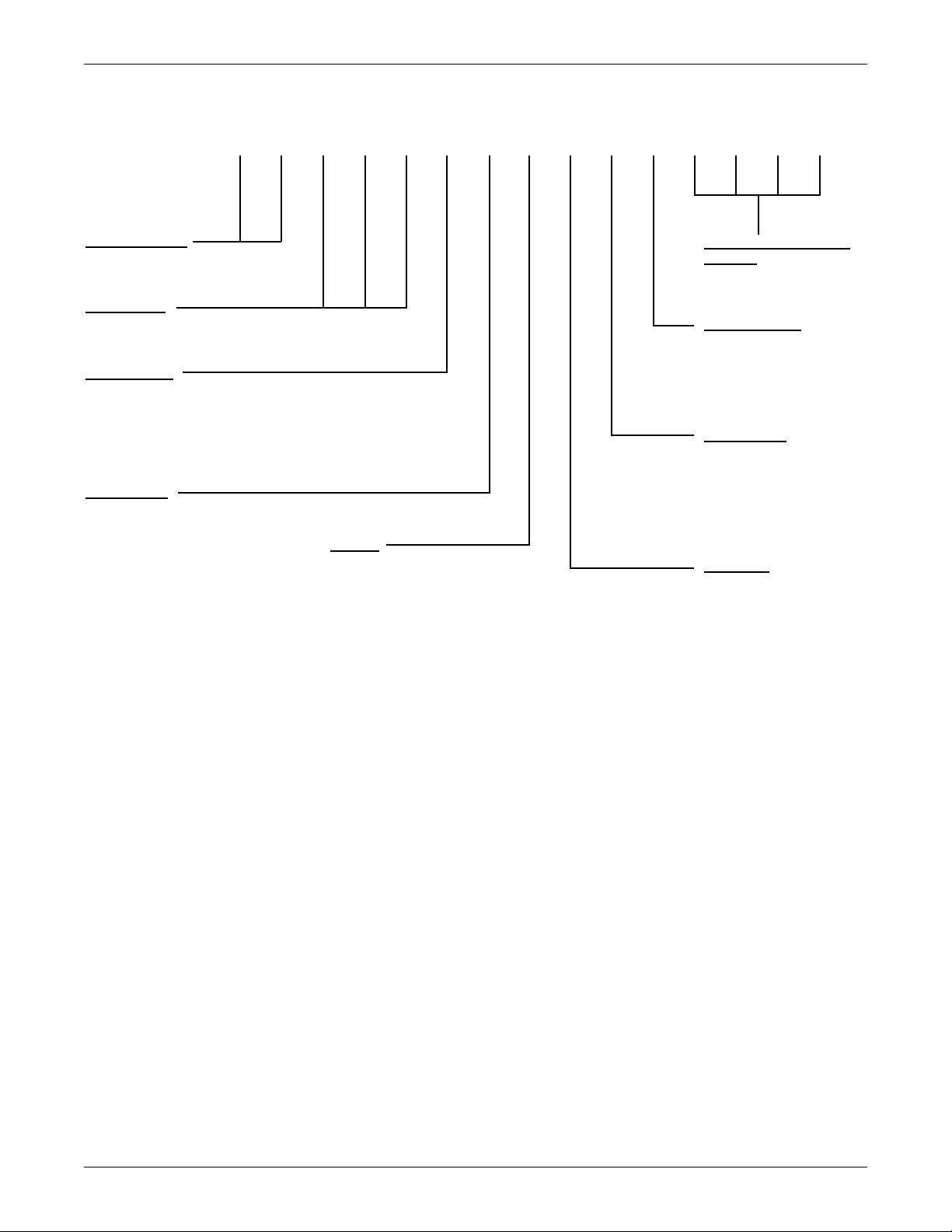
Figure 3 Liebert DS model number nomenclature
Liebert DS Components and Nomenclature
1
D2S30
Air Distribution
DS = Downflow Standard
VS = Upflow Standard
Nominal kW
028,035, 042, 053,
070, 077, 105
Cooling Type
A = Air-Cooled
D = Dual-Cooling, Air-Cooled
W = Water/Glycol
K = GLYCOOL
H = Dual-Cooling (Water/Glycol)
Compressor
U - Semi-hermetic with four-step, R-407C
S - Scroll, R-407C
D - Digital Scroll, R-407C
M - Semi-hermetic
with four-step, R-22
R - Scroll, R-22
G - Digital Scroll, R-22
4
355
Voltage
A - 460/3/60
B - 575/3/60
C - 208/3/60
D - 230/3/60
2 - 380/3/60
A
7
6
U
8
A90
10311I12*13*14*15
*
Factory Configuration
Number
Humidification
0 - None
I - Infrared
S - Steam Generating
Canister
Reheat Type
0 - None
E - Three-stage
electric
S - SCR
W - Hot water
Rev Level
= Rev 0
J - 200/3/50
M - 380-415/3/50
5
Page 16
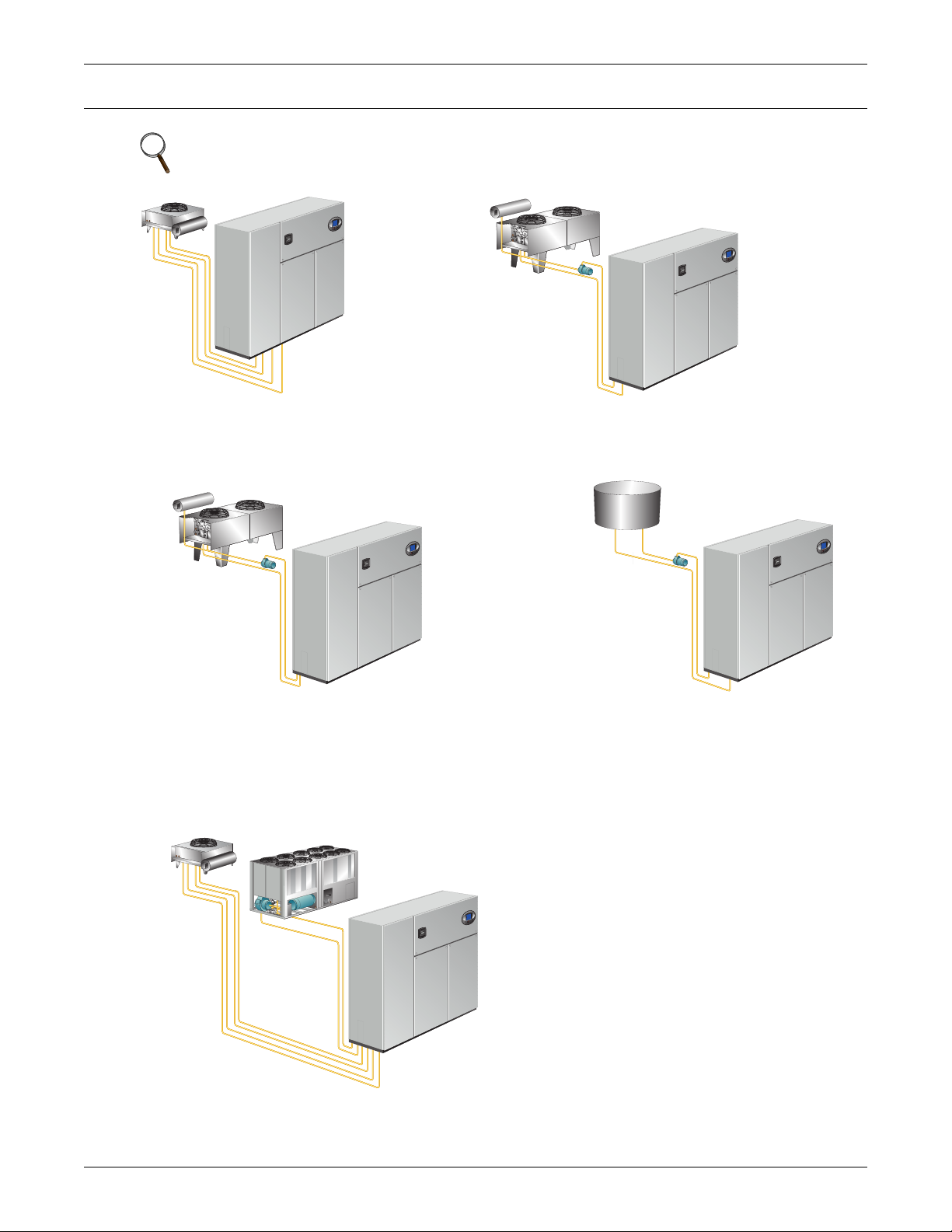
2.0 COOLING CONFIGURATIONS
t
s
NOTE
All field-installed piping must comply with applicable local, state and federal codes.
Cooling Configurations
Air-Cooled
Air-cooled unit piping is spun closed from
the factory and contain a nitrogen holding
charge. Each installation requires refrigerant
piping to a condenser.
GLYCOOL
GLYCOOL units are factory-charged and tested. Field-installed
piping is required from the unit to the drycooler and pump
package. An additional coil is included for use when fluid
emperatures are sufficiently low (below room temperature).
Cooling is provided by circulating cold glycol through this
econd coil, reducing compressor operation.
Glycol-cooled units are factory-charged and
tested. Field-installed piping is required from the
unit to the drycooler and pump package.
Glycol-Cooled
Water-Cooled
Water-cooled units are factory-charged and
tested. Field-installed water piping is
required from the unit to the cooling tower.
Dual-Cool
This system has all of the features of a compressorized
system, but adds a second cooling coil that is connected
to a source of chilled water. Cooling is provided by
circulating water through this second coil and reducing
compressor operation.
6
Page 17
3.0 PRE-INSTALLATION GUIDELINES
3.1 Room Preparation
• Verify that the floor is level, solid and sufficient to support the unit. See Table 2 for unit weights.
• Confirm that the room is properly insulated and has a sealed vapor barrier.
• For proper humidity control, keep outside or fresh air to an absolute minimum (less than 5% of
total air circulated in the room).
• Do not install Liebert DS units in an alcove or at the end of a long, narrow room.
• Install the units as close as possible to the largest heat load.
• Allow at least the minimum recommended clearances for maintenance and service. See
Figures 6 through 21 for dimensions.
• Emerson recommends installing an under-floor water detection system. Contact your local Emerson representative for information.
3.2 Air Distribution—Downflow Units
• Verify that the raised floor has been properly sized for the unit’s airflow and the room is free of
airflow restrictions.
• Perforated floor tiles in the raised floor should ensure minimal pressure loss.
• The raised floor must provide 7-1/2" (191mm) of clearance.
• Ensure that there is adequate clearance above the unit for service, such as replacing filters.
• Optional plenums are available for downflow unit ducting.
Pre-Installation Guidelines
Figure 4 Downflow unit ducting and plenum ducting
Field-Fabricated
Ductwork
Field Service Access
for filter replacement
(minimum height of
Provided Condenser
Access (water, glycol
and GLYCOOL
units only)
DIRECT UNIT DUCTING
Provided Condenser
Access (water, glycol
and GLYCOOL units only)
12" [305mm]; minimum
distance from unit,
2" [51mm])
Optional
Liebert
Plenum
Field-Fabricated
Ductwork
Provided Service
Access Door for
filter replacement
Liebert Plenum - Refer to plenum
installation sheet 186582P1
included in the plenum package.
7
PLENUM DUCTING
Page 18
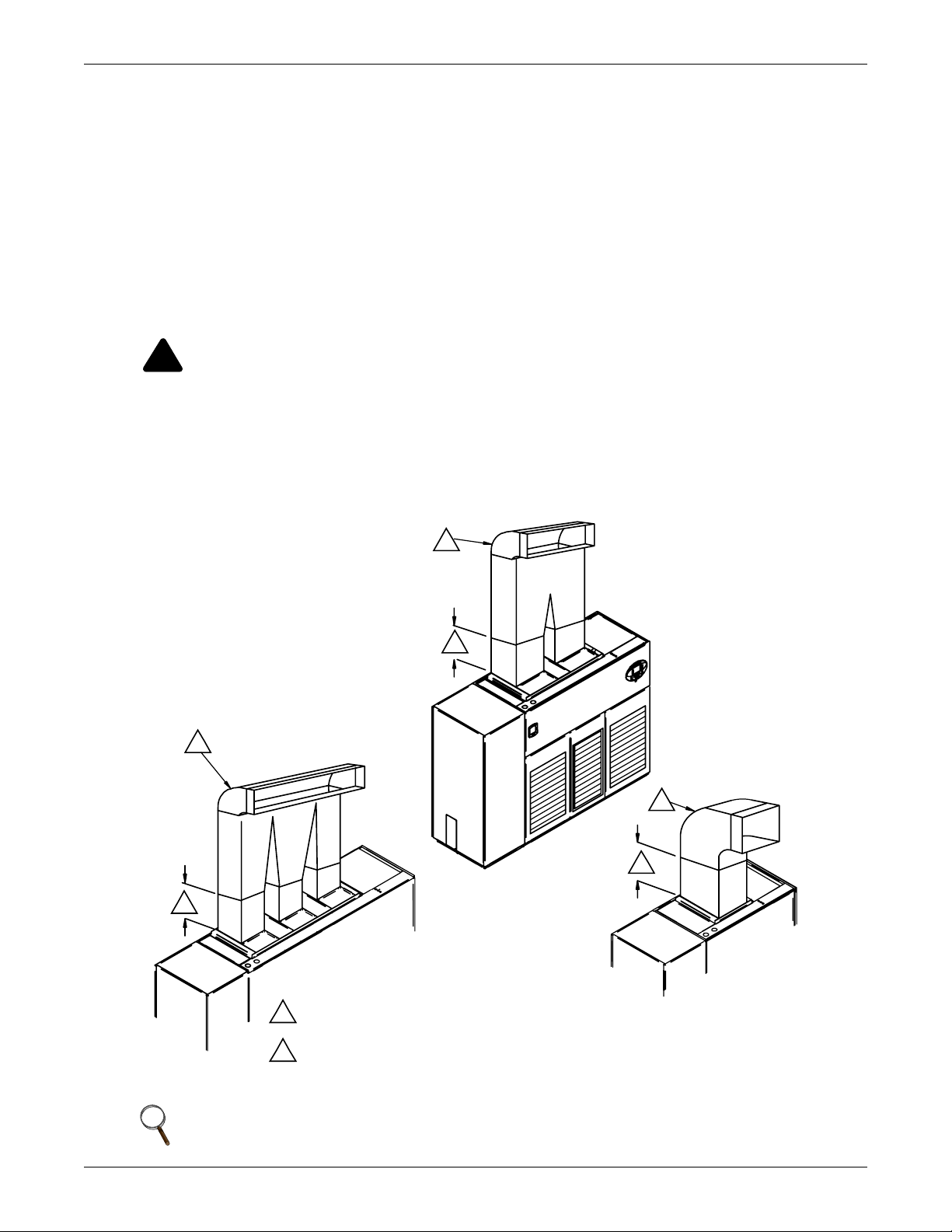
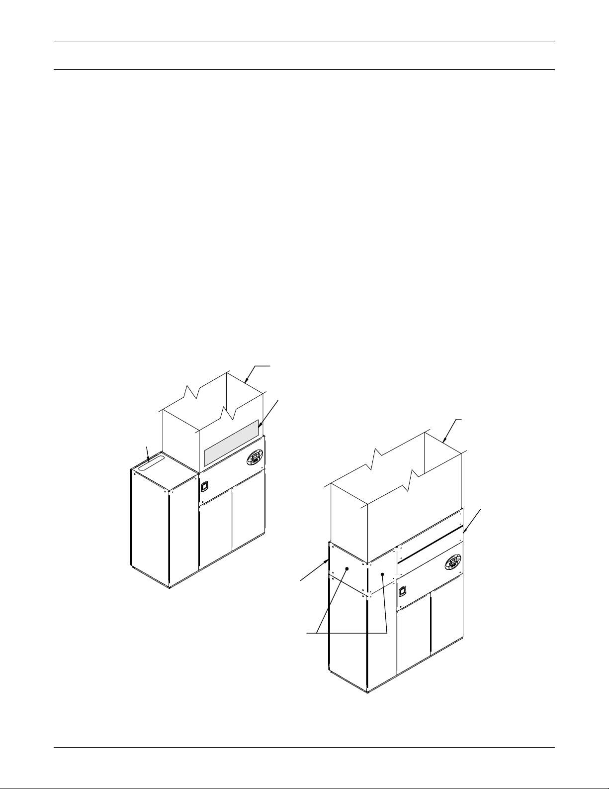
3.3 Air Distribution—Upflow Units
Various configurations are available:
• Front return
• Rear return
•Top-front supply
• Top-rear supply
For in-room applications with supply and return grilles, several feet of clearance must be maintained
at the intake and discharge of the unit.
Upflow rear-return configurations use a filter box attached to the back of the Liebert DS. Allow 25"
(635 mm) on one side of the unit for access to the rear return filter box. Refer to the rear return installation sheet, 187230P1, inside the rear return filter box package.
WARNING
!
Risk of high-speed moving parts. Can cause injury or death.
Disconnect all local and remote electric power supplies before working in the unit.
Do not operate upflow units without installing a plenum, ductwork or guard over the blower
opening(s) on the top surface of the unit cabinet.
Ductwork must be connected to the blower(s), or a plenum must be installed on the blower
deck for protection from rotating blower wheel(s) on upflow units.
Pre-Installation Guidelines
Figure 5 Upflow ducting configurations
2
1
2
1
2
1
1
Straight section of duct off of unit to be 1.5 to 2.5 times
the longest blower dimension.
Typical ducting shown; ducting may run to either side.
2
* Follow standard practices on all duct work.
NOTE
Drain traps are qualified to a return duct static of negative 1.5 i.w.g. (-1.5 i.w.g).
8
DPN001156
Rev. 0
Page 19

3.4 Connections and System Setup
• Plan the routing of wiring, piping and ductwork to the unit. See Figure 55 and Figures 66
through 79 for unit connection locations.
• Water/glycol and GLYCOOL units utilizing a drycooler may require an optional aquastat setting.
See Tables 58 through 57 aquastat setting guidelines. Applications with the optional stat setting require field piping to be insulated to prevent condensation.
• The unit requires a drain, which must comply with all applicable codes. This drain line may contain boiling water. See 8.1.1 - Condensate Piping—Field-Installed for details.
• Three-phase electrical service is required for all models. Electrical service must conform to
national and local electrical codes. See equipment nameplate for details.
• If seismic requirements apply, consult your local Emerson representative for information about a
seismic-rated floor stand.
3.5 Operating Conditions
• The Liebert DS must be operated in a conditioned space within the operating envelope ASHRAE
recommends for data centers: Maximum temperature of 77°F (25°C) DB and 55% RH or maximum WB of 65.5°F (18.6°C).
Operating outside this envelope can decrease equipment reliability.
• Return air to the unit must be no cooler than the ASHRAE recommendation of 68°F (20°C) DB
and 40% RH or minimum WB of 54°F (12.2°C) for proper unit operation.
Operating below this can decrease equipment reliability.
Pre-Installation Guidelines
Refer to ASHRAE’s publication, “Thermal Guidelines for Data Processing Environments.”
9
Page 20

4.0 LIEBERT DS DIMENSIONS AND WEIGHTS
Table 1 Shipping dimensions—domestic and export, inches (mm)
028/035/ 042 053/070/ 077 105
Model Number
DS/VSAS, DS/VSAD, DS/VSAR, DS/VSAG,
DS/VSDS, DS/VSDD, DS/VSDR, DS/VSDG
DS/VSAU, DS/VSAM, DS/VSDU, DS/VSDM
DS/VSWS, DS/VSWD, DS/VSWR, DS/VSWG
DS/VSHS, DS/VSHD, DS/VSHR, DS/VSHG
DS/VSWU, DS/VSWM, DS/VSHU, DS/VSHM
Table 2 Shipping weights—approximate, kg
Size
8-12 Ton
15 Ton
20 Ton
22 Ton
30 Ton
Cooling
Type
Air
Air D/C
W/G
G/C
Air
Air D/C
W/G
G/C
Air
Air D/C
W/G
G/C
Air
Air D/C
W/G
G/C
Air
Air D/C
W/G
G/C
Compressor
Type
Semi 1918 2088 1968 2138
Scroll 1608 1778 1658 1828
Semi 2068 2238 2118 2288
Scroll 1758 1928 1808 1978
Semi 2068 2238 2118 2288
Scroll 1918 2088 1968 2138
Semi 2218 2388 2268 2438
Scroll 2068 2238 2118 2288
Semi 2512 2712 2512 2712
Scroll 2070 2260 2220 2410
Semi 2692 2892 2692 2892
Scroll 2250 2440 2400 2590
Semi 2812 3012 2812 3012
Scroll 2382 2582 2532 2732
Semi 2992 3192 2992 3192
Scroll 2562 2762 2712 2912
Semi 2562 2762 2662 2862
Scroll 2120 2310 2220 2410
Semi 2742 942 2842 3042
Scroll 2300 2490 2400 2590
Semi 2862 3062 2962 3162
Scroll 2432 2632 2532 2732
Semi 3042 3242 3142 3342
Scroll 2612 2812 2712 2912
Semi 2612 2812 2662 2862
Scroll 2170 2360 2220 2410
Semi 2792 2992 2842 3042
Scroll 2350 2540 2400 2590
Semi 2912 3112 2962 3162
Scroll 2470 2660 2532 2732
Semi 3092 3292 3142 3342
Scroll 2650 2840 2712 2912
Semi 3223 3443 3183 3403
Scroll 3103 3323 3063 3283
Semi 3583 3803 3513 3733
Scroll 3463 3683 3393 3613
Semi 3593 3813 3553 3773
Scroll 3473 3693 3433 3653
Semi 3953 4173 3883 4103
Scroll 3833 4053 3763 3983
LxW x H, in (mm) Lx W xH, in (mm) Lx W x H, in (mm)
90x42 x 82
(2286x1067 x 2083)
Downflow Unit Weight, lb Upflow Unit Weight, lb
Domestic Export Domestic Export
Liebert DS Dimensions and Weights
102x42 x 82
(2591x 1067 x 2083
136x 42x82
114x42x82
(2896x1067 x 2083)
(3454x1067 x 2083)
10
Page 21
Liebert DS Dimensions and Weights
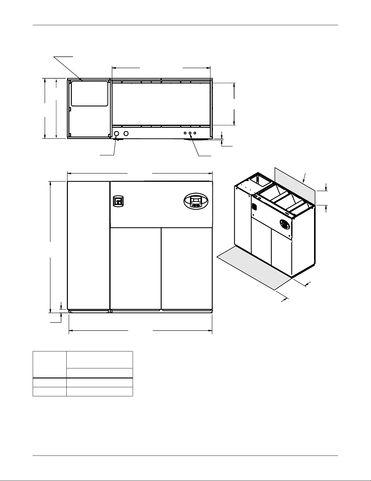
S
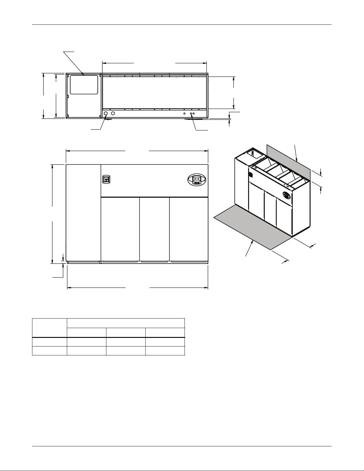
Figure 6 Cabinet and floor planning dimensions—downflow, air-cooled, 28-42kW (8-12 ton),
semi-hermetic compressor models
econdary Refrigerant
Piping Entrance
Opening
Notes:
24-3/8"
(619mm)
Secondary Entrance
Low Volt Connections
Opening
3/4"
(19mm)
Bezels
Filters are accessible
through top of unit onl y.
Downflow electrical
connections can be made
from top or bottom of unit.
Minimum clearance
required for filter
replacement
33"
(838mm)
35"
(889mm)
Secondary Entrance
High Volt Connection(s)
56-7/8"
(1445mm)
Air Inlet Opening
Top View
86"
(2184mm)
76"
(1930mm)
34"
(864mm)
DPN000795
Rev. 3
2"
(51mm)
Shaded areas indicate a
recommended minimum
clearance for component
access.
Front View
85"
(2159mm)
Table 3 Weights for downflow, air-cooled, 28-42kW (8-12 ton), semi-hermetic compressor models
Dry Weight - lb. (kg),
Approximate
Model No.
Air-Cooled 1780 (809)
Dual-Cool 1930 (877)
028, 035, 042
15"
(381mm)
11
Page 22
Liebert DS Dimensions and Weights
Figure 7 Cabinet and floor planning dimensions—downflow, air-cooled, 28-42kW (8-12 ton), scroll
compressor models
Secondary Refrigerant
Piping Entrance
56-7/8"
(1445mm)
Opening
Notes: Filters are accessible
through top of unit only.
Downflow electrical
connections can be made
24-3/8"
from top or bottom of unit.
(619mm)
Opening
3/4"
Bezels
(838mm)
35"
(889mm)
33"
Air Inlet Opening
(19mm)
Minimum required
for filter replacement
Secondary Entrance
High Volt Connection(s)
Top View
Secondary Entrance
Low Volt Connections
73"
(1854mm)
76"
(1930mm)
34" (864mm)
Shaded area indicates a
recommended minimum
clearance for component
2"
(51mm)
Table 4 Weights for downflow, air-cooled, 28-42kW (8-12 ton), scroll compressor models
Dry Weight, lb (kg),
Approximate
Model No. 028, 035, 042
Air-Cooled 1470 (668)
Dual-Cool 1620 (736)
Front View
72"
(1829mm)
access.
DPN000796
Rev. 2
15"
(381mm)
12
Page 23
Liebert DS Dimensions and Weights
Figure 8 Cabinet and floor planning dimensions—downflow, water/glycol/GLYCOOL, 28-42kW (8-12 ton),
all compressor models
Condenser Cleanout Access
33"
(838mm)
35"
(889mm)
Secondary Condenser
Fluid Piping Entrance
Secondary Entrance
High Volt Connection(s)
56-7/8"
(1445mm)
Air Inlet Opening
Top View
86"
(2184mm)
Opening
Secondary Entrance
Low Volt Connections
24-3/8"
(619mm)
Opening
Notes: Filters are accessible
through top of unit only.
Downflow electrical
connections can be made
from top or bottom of unit.
Bezels
3/4"
(19mm)
Required for
condenser cleanout
24"
(610mm)
Minimum required
for filter replacement
(381mm)
15"
76"
(1930mm)
34" (864mm)
Shaded area indicates a
recommended minimum
clearance for component
2"
(51mm)
Front View
85" (2159mm)
access.
DPN000894
Rev. 3
Table 5 Weights for downflow, water/glycol/GLYCOOL, 28-42kW (8-12 ton), all compressor models
Dry Weight - lb. (kg),
Approximate
Compressor Type
Semi-Hermetic Compressor
Scroll or Digital Scroll Compressor
Model 028, 035, 042
Water/Glycol 1930 (877)
GLYCOOL/Dual-Cool 2080 (945)
Water/Glycol 1780 (809)
GLYCOOL/Dual-Cool 1930 (877)
13
Page 24
Liebert DS Dimensions and Weights
Figure 9 Cabinet and floor planning dimensions—downflow, air-cooled, 53-77kW (15-22 ton),
semi-hermetic compressor models
Second Refrigerant
Piping Entrance
33"
(838mm)
35"
(889mm)
80"
Opening
(2032mm)
Air Inlet Opening
24-3/8"
(619mm)
Notes: Filters are accessible
through top of unit only.
Downflow electrical
connections can be made
Opening
from top or bottom of unit.
3/4"
Bezels
(19mm)
Secondary Entrance
High Volt Connection(s)
76"
(1930mm)
2"
(51mm)
Top View
109"
(2769mm)
Front View
108"
(2743mm)
Secondary Entrance
Low Volt Connections
Shaded area indicates a
recommended minimum
clearance for component
access.
Minimum required
for filter replacement
15"
(381mm)
34"
(864mm)
DPN000924
Rev. 2
Table 6 Weights for downflow, air-cooled, 53-77kW (15-22 ton), semi-hermetic compressor models
Dry Weight, lb (kg) Approximate
Model
Air-Cooled 2350 (1069) 2400 (1091) 2450 (1114)
Dual-Cool 2530 (1150) 2580 (1173) 2630 (1196)
053 070 077
14
Page 25
Liebert DS Dimensions and Weights
Figure 10 Cabinet and floor planning dimensions—downflow, air-cooled, 53-77kW (15-22 ton), scroll
compressor models
Secondary Refrigerant
Piping Entrance
33"
(838mm)
35"
(889mm)
Secondary Entrance
High Volt Connection(s)
76"
(1930mm)
Opening
80"
(2032mm)
Air Inlet Opening
Top View
98"
(2489mm)
Notes: Filters are accessible
only through top of unit.
Downflow electrical
connections can be made
from top or bottom of unit.
24-5/8"
(625mm
Opening
(19mm) Bezels
Secondary Entrance
Low Volt Connections
3/4"
Minimum required
for filter replacement
15"
(381mm)
(864mm)
2"
(51mm)
97"
(2464mm)
Front View
Shaded area indicates a
recommended minimum
clearance for component
access.
DPN000925
Rev. 1
Table 7 Weights for downflow, air-cooled, 53-77kW (15-22 ton), scroll compressor models
Dry Weight, lb (kg) Approximate
Model No.
Air-Cooled 1920 (873) 1970 (896) 2020 (919)
Dual-Cool 2100 (955) 2150 (978) 2200 (1000)
053 070 077
34"
15
Page 26
Liebert DS Dimensions and Weights
Figure 11 Cabinet and floor planning dimensions—downflow, water/glycol/GLYCOOL, 53-77kW
(15-22 ton), all compressor models
Condenser Cleanout Access
80" (2032mm)
Opening
(838mm)
35"
(889mm
76"
(1930mm)
33"
Secondary Condenser
Fluid Piping Entrance
Secondary Entrance
High Volt Connection(s)
Air Inlet Opening
TOP VIEW
109"
(2769mm)
24-5/8" (625mm)
Opening
Secondary Entrance
Low Volt Connections
(610mm)
Notes: Filters are accessible
through top of unit only.
Downflow electrical
connections can be made
from top or bottom of unit.
3/4" (20mm)
Bezels
Required for
condenser cleanout
24"
Minimum required
for filter replacement
15"
(381mm)
34"
(864mm)
DPN000931
Rev. 3
2"
(51mm)
FRONT VIEW
108"
(2743mm)
Shaded area indicates a
recommended minimum
clearance for component
access.
Table 8 Weights for downflow, water/glycol/GLYCOOL, 53-77kW (15-22 ton), all compressor models
Compressor
Type Model
Semi-Hermetic
Compressor
Scroll or
Digital Scroll
Compressor
Water/Glycol 2650 (1205) 2700 (1228) 2750 (1250)
GLYCOOL/Dual-Cool 2830 (1287) 2880 (1310) 2930 (1332)
Water/Glycol 2220 (1010) 2270 (1032) 2320 (1055)
GLYCOOL/Dual-Cool 2400 (1091) 2450 (1114) 2500 (1137)
Dry Weight, lb (kg), Approximate
053 070 077
16
Page 27
Liebert DS Dimensions and Weights
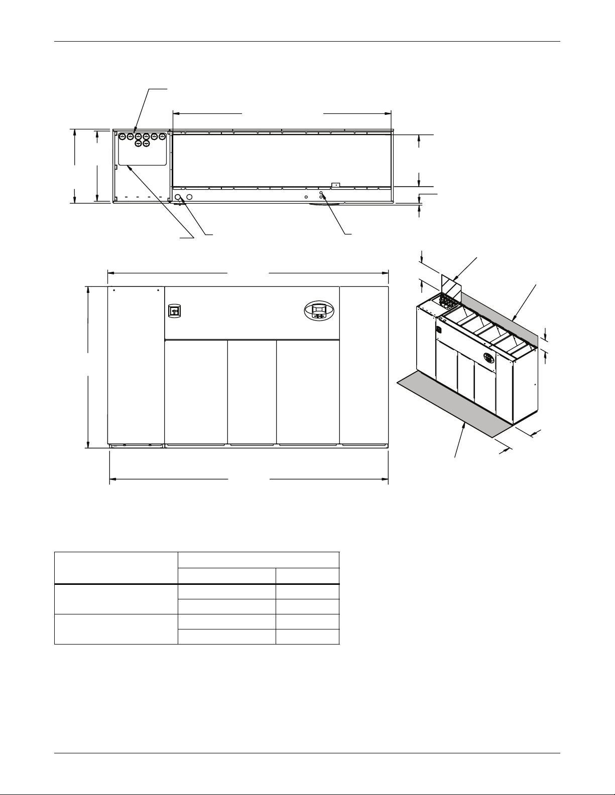
Figure 12 Cabinet and floor planning dimensions—downflow, air-cooled, 105kW (30 ton), all compressor
models
(838mm)
35"
(889mm)
76"
(1930mm)
33"
Second Refrigerant
Piping Entrance
102-13/16"
(2611mm)
Air Inlet Opening
Top View
Secondary Entrance
High Volt Connection(s)
132"
(3353mm)
Opening
Secondary Entrance
Low Volt Connections
Notes: Filters are accessible
only through top of unit.
Downflow electrical
connections can be made
from top or bottom of unit.
24-3/8"
(619mm)
Opening
3/4"
Bezels
(19mm)
Minimum required
for filter replacement
15"
(381mm)
Shaded area indicates a
recommended minimum
Front View
131"
clearance for component
access.
(3327mm)
Table 9 Weights for downflow, air-Cooled, 105kW (30 ton), all compressor models
Dry Weight, lb (kg) approximate
Compressor Type
Semi-Hermetic Compressor
Scroll Compressor
Model 105
Air-Cooled 3040 (1382)
Dual-Cool 3400 (1545)
Air-Cooled 2920 (1327)
Dual-Cool 3280 (1491)
34" (864mm)
DPN001012
Rev. 2
17
Page 28
Liebert DS Dimensions and Weights
Figure 13 Cabinet and floor planning dimensions—downflow, water/glycol/GLYCOOL, 105kW (30 ton), all
compressor models
(838mm)
35"
(889mm)
76"
(1930mm)
33"
Secondary Condenser
Fluid Entrance
Condenser Cleanout Access
102-13/16"
(2611mm)
Air Inlet Opening
Top View
Secondary Entrance
High Volt Connection(s)
132"
(3353mm)
Opening
Notes: Filters are accessible
only through top of unit.
Downflow electrical
connections can be made
from top or bottom of unit.
24-3/8"
(619mm)
Secondary Entrance
Low Volt Connections
24"
(610mm)
Opening
3/4"
(19mm)
Bezels
Required for
condenser cleanout
Minimum required
for filter replacement
15"
(381mm)
Front View
131"
(3327mm)
Shaded area indicates a
recommended minimum
clearance for component
access.
DPN001013
Table 10 Weights for downflow, water/glycol/GLYCOOL, 105kW (30 ton), all compressor models
Dry Weight, lb (kg) approximate
Compressor Type
Semi-Hermetic Compressor
Scroll Compressor
Model 105
Water/Glycol 3410 (1550)
GLYCOOL/Dual-Cool 3770 (1714)
Water/Glycol 3290 (1495)
GLYCOOL/Dual-Cool 3650 (1659)
34"
(864mm)
Rev. 2
18
Page 29
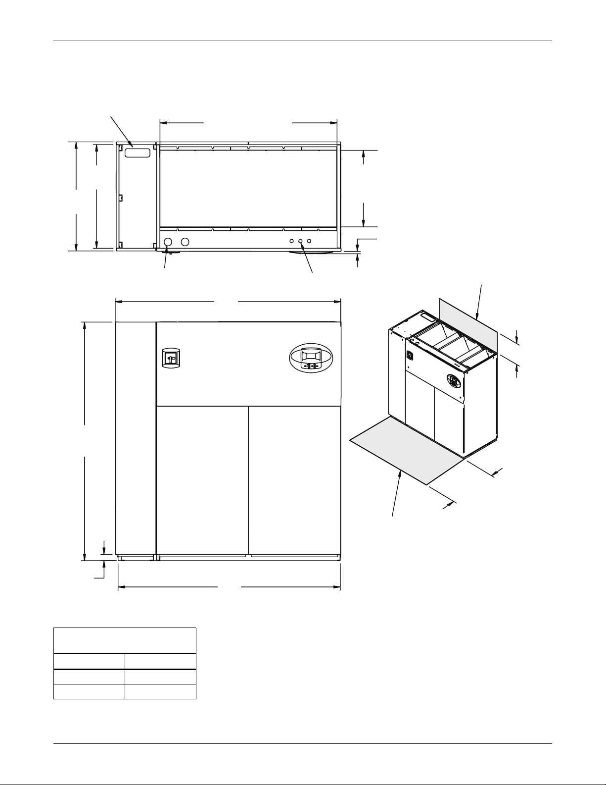
Liebert DS Dimensions and Weights
f
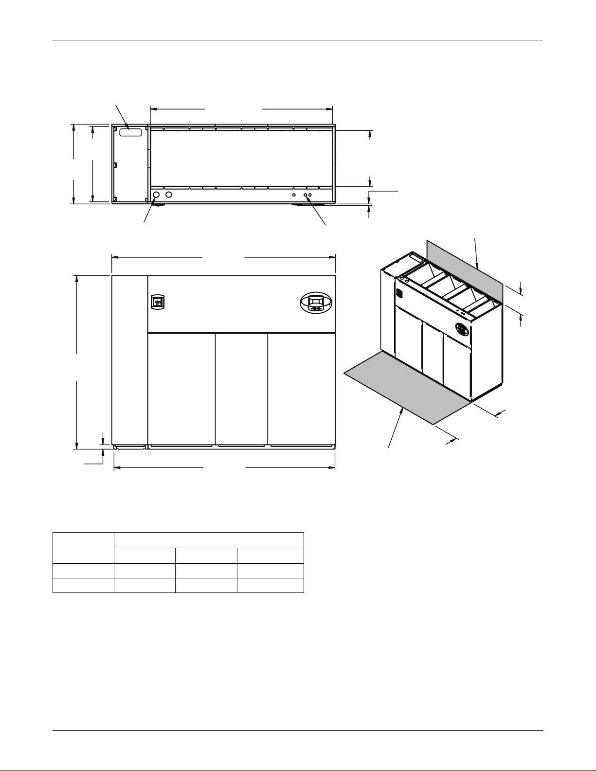
Figure 14 Cabinet and floor planning dimensions—upflow, air-cooled 28-42kW (8-12 ton), semi-hermetic
compressor models
33"
(838mm)
35"
(889mm)
High Volt Connection(s)
1-1/2"
(38mm)
Alternate Re
Piping Entrance
(2184mm)
rigerant
Top View
86"
(19mm)
Bezels
Low Volt Connection(s)
3/4"
Minimum required
for blower replacement
24"
(610mm)
76"
(1930mm)
34"
(864mm)
Shaded area indicates a
recommended minimum
clearance for component
access.
2"
(51mm)
Front View
85"
(2159mm)
Note: Front air return unit shown. For rear
return unit, in addition to front service area
shown, also include 25" (635mm) on one side
of unit for access to rear return filter box.
See DPN001196, Figure 28.
DPN001162
Table 11 Weight for upflow, air-cooled, 28-42kW (8-12 ton), semi-hermetic compressor models
Dry Weight, lb (kg)
approximate
Model No.
Air-Cooled 1830 (830)
Dual-Cool 1980 (898)
028-042
Rev. 1
19
Page 30
Liebert DS Dimensions and Weights
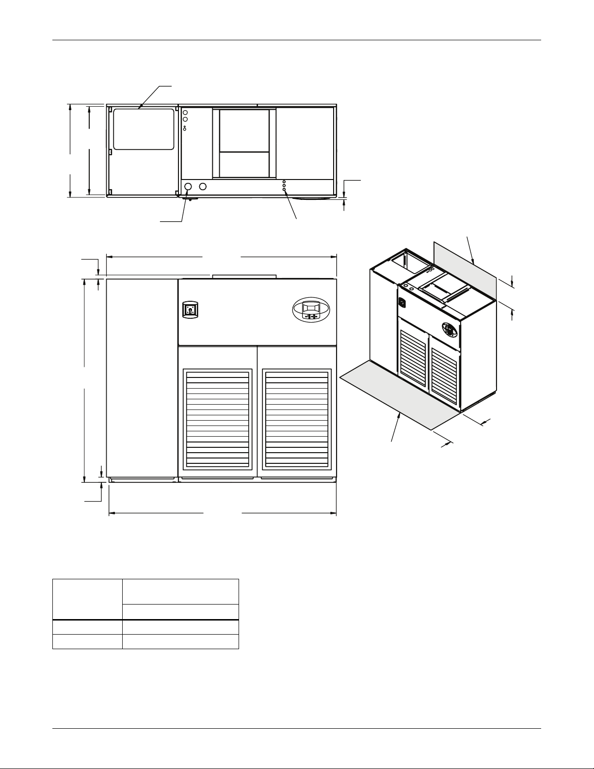
Figure 15 Cabinet and floor planning dimensions—upflow, air-cooled 28-42kW (8-12 ton), scroll or digital
scroll compressor models
Alternate Refrigerant
Piping Entrance
33"
(838mm)
35"
(889mm)
3/4"
(19mm)
Bezels
High Volt Connection(s)
1-1/2"
(38mm)
76"
(1930mm)
2"
(51mm)
TOP VIEW
73"
(1854mm)
FRONT VIEW
72"
(1829mm)
Low Volt Connection(s)
Shaded area indicates a
recommended minimum
clearance for component
access.
Note: Front air return unit shown. For rear
return unit, in addition to front service area
shown, also include 25" (635mm) on one side
of unit for access to rear return filter box.
See DPN001196, Figure 28.
Minimum required
for blower replacement
24"
(610mm)
34"
(864mm)
DPN001163
Rev. 1
Table 12 Weight for upflow, air-cooled, 28-42kW (8-12 ton), scroll or digital scroll compressor models
Dry Weight, lb (kg)
approximate
Model No.
Air-Cooled 1520 (689)
Dual-Cool 1670 (758)
028-042
20
Page 31

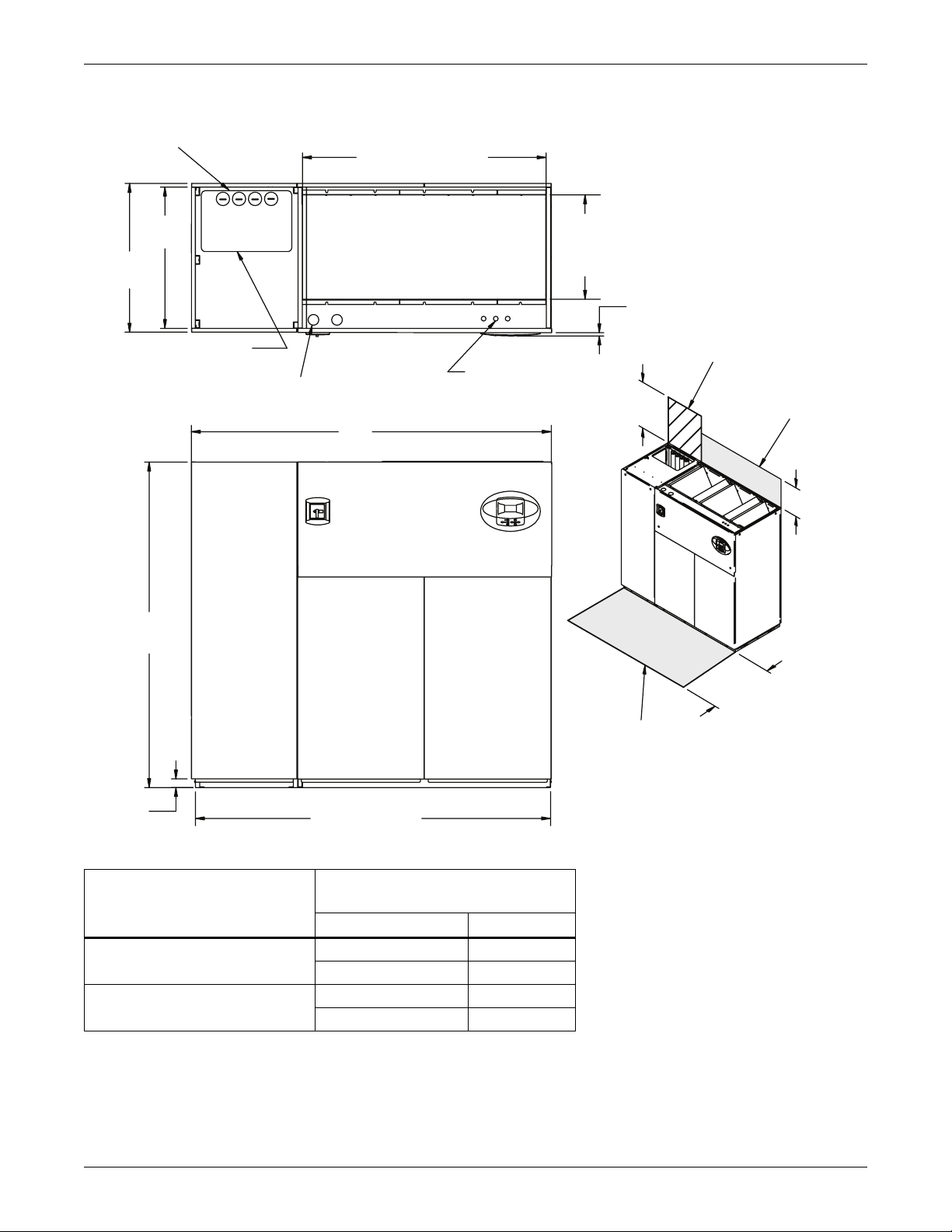
Liebert DS Dimensions and Weights
(
C
Figure 16 Cabinet and floor planning dimensions—upflow, water/glycol/GLYCOOL, 28-42kW (8-12 ton), all
compressor models
33"
(838mm)
35"
(889mm)
Alternate Refrigerant
Piping Entrance
High Volt Connection(s)
1-1/2"
(38mm)
ondenser Cleanout Access
TOP VIEW
86"
(2184mm)
Note: Front air return unit shown. For rear
return unit, in addition to front service area
shown, also include 25" (635mm) on one side
of unit for access to rear return filter box.
See DPN001196, Figure 28
(19mm) Bezels
Low Volt Connection(s)
3/4"
Required for
condenser cleanout
Minimum required
for blower replacement
24"
(610mm)
76"
(1930mm)
34"
Shaded area indicates a
(864mm)
recommended minimum
clearance for component
access.
FRONT VIEW
2"
(51mm)
85"
2159mm)
Table 13 Weights for upflow, water/glycol/GLYCOOL, 28-42kW (8-12 ton), all compressor models
Dry Weight, lb (kg) approximate
Compressor Type
Semi-Hermetic
Scroll or Digital Scroll
GLYCOOL/Dual-Cool 1980 (898)
Model 028-042
Water/Glycol 1980 (898)
GLYCOOL/Dual-Cool 2130 (966)
Water/Glycol 1830 (830)
DPN001164
Rev. 1
21
Page 32

Liebert DS Dimensions and Weights
Figure 17 Cabinet and floor planning dimensions—upflow, air-cooled, 53-77kW (15-22 ton), semi-hermetic
compressor models
Alternate Refrigerant
Piping Entrance
33"
(838mm)
35"
(889mm)
3/4"
(19mm)
Bezels
Minimum required
for blower replacement
Top View
Low Volt Connection(s)
24"
(610mm)
1-1/2"
(38mm)
High Volt Connection(s)
109"
(2769mm)
76"
(1930mm)
34"
(864mm)
Shaded area indicates a
recommended minimum
clearance for component
access.
DPN001165
Rev. 1
2"
(51mm)
108"
(2743mm)
Front View
Note: Front air return unit shown. For rear return unit,
in addition to front service area shown, also include
25" (635mm) on one side of unit for access to rear return
filter box. See DPN001196, Figure 28.
Table 14 Weights for upflow, air-cooled, 53-77kW (15-22 ton), semi-hermetic compressor models
Dry Weight, lb (kg)
approximate
Model
053 070, 077
Air-Cooled 2350 (1069) 2500 (1134)
Dual
-Cool 2530 (1150) 2680 (1216)
22
Page 33

Liebert DS Dimensions and Weights
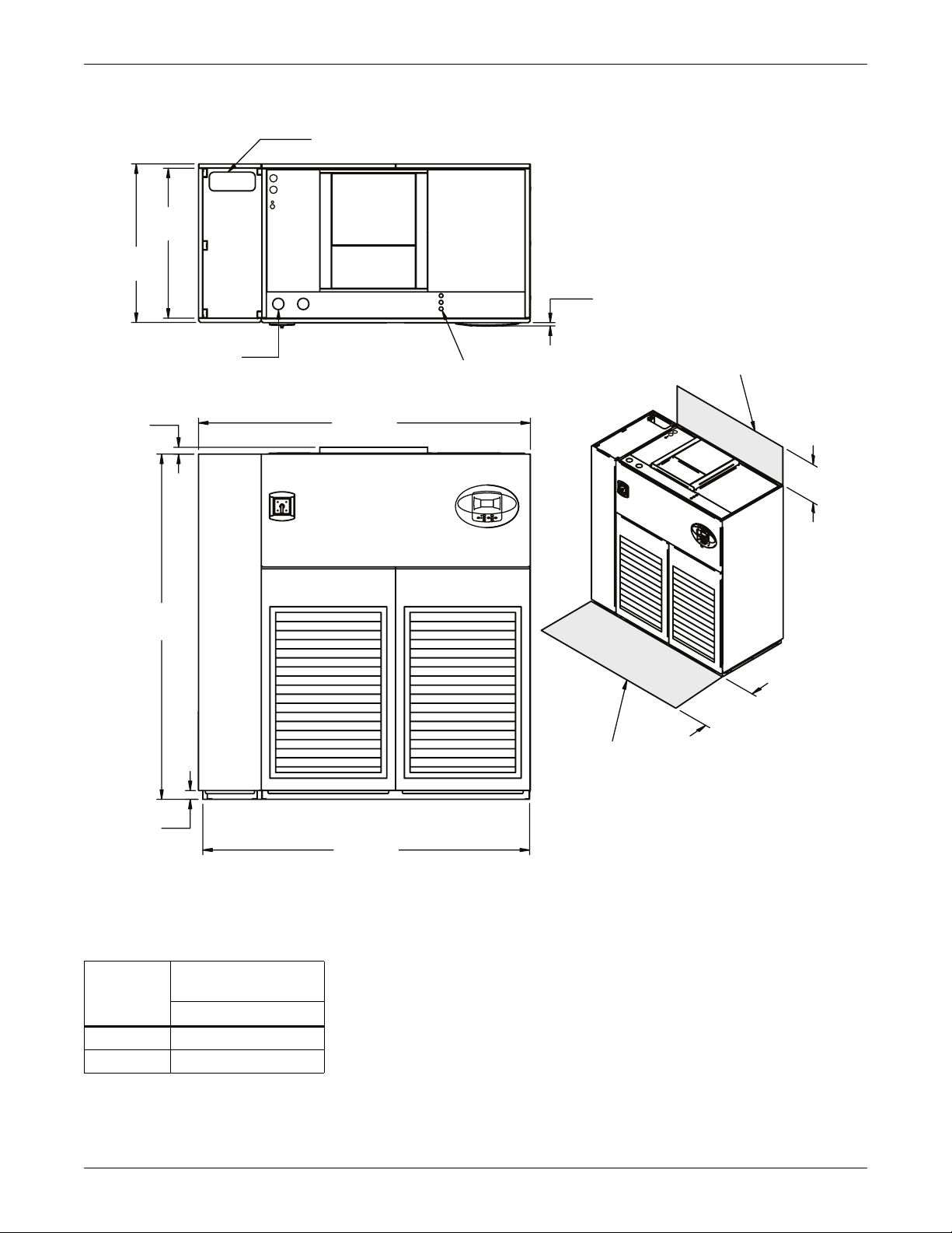
Figure 18 Cabinet and floor planning dimensions—upflow, air-cooled, 53-77kW (15-22 ton), scroll or digital
scroll compressor models
Alternate Refrigerant
Piping Entrance
33"
(838mm)
35"
(889mm)
3/4"
(19mm)
Minimum required
for blower replacement
Bezels
1-1/2"
(38mm)
76"
(1930mm)
2"
(51mm)
High Volt
Connection(s)
Top View
98"
(2489mm)
97"
(2464mm)
Front View
Low Volt
Connection(s)
24"
(610mm)
34"
(864mm)
Shaded area indicates a
recommended minimum
clearance for component
access.
Note: Front air return unit shown. For rear return unit,
in addition to front service area shown, also include
25" (635mm) on one side of unit for access to rear return
filter box. See DPN001196, Figure 28.
DPN001166
Rev. 1
Table 15 Weight for upflow, air-cooled, 53-77kW (15-22 ton), scroll or digital scroll compressor models
Dry Weight, lb (kg) approximate
Model No.
Air-Cooled 2070 (939)
Dual-Cool 2250 (1021)
053, 070, 077
23
Page 34

Liebert DS Dimensions and Weights
A
Figure 19 Cabinet and floor planning dimensions—upflow, water/glycol/GLYCOOL, 53-77kW (15-22 ton),
all compressor models
33"
(838mm)
35"
(889mm)
lternate Condenser
Fluid Piping Entrance
High Volt Connection(s)
Top View
Low Volt
Connection(s)
3/4"
(19mm)
Bezels
Required for
condenser cleanout
Minimum required
for blower replacement
1-1/2"
(38mm)
109"
(2769mm)
24"
(610mm)
76"
(1930mm)
34"
(864mm)
Shaded area indicates a
recommended minimum
2"
(51mm)
108"
(2743mm)
Front View
Note: Front air return unit shown. For rear return unit,
in addition to front service area shown, also include
25" (635mm) on one side of unit for access to rear return
filter box. See DPN001196, Figure 28.
clearance for component
access.
DPN001167
Rev. 1
Table 16 Weights for upflow, water/glycol/GLYCOOL, 53-77kW (15-22 ton), all compressor models
Dry Weight, lb (kg) approximate
Compressor Type
Semi-Hermetic Compressor
Scroll or Digital Scroll Compressor
Model 053 070, 077
Water/Glycol 2650 (1205) 2800 (1270)
GLYCOOL/Dual-Cool 2830 (1287) 2980 (1352)
Water/Glycol 2370 (1075)
GLYCOOL/Dual-Cool 2550 (1157)
24
Page 35

Liebert DS Dimensions and Weights
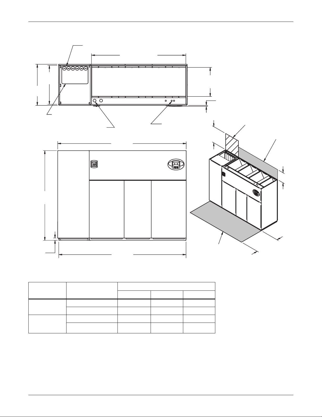
Figure 20 Cabinet and floor planning dimensions—upflow, air-cooled, 105kW (30 ton), all
Alternate Refrigerant
Piping Entrance
33"
(838mm)
35"
(889mm)
1-1/2"
(38mm)
(1930mm)
76"
High Volt
Connection(s)
TOP VIEW
132"
(3353mm)
Low Volt
Connection(s)
3/4"
(19mm)
Bezels
Minimum required
for blower replacement
24" (610mm)
2"
(51mm)
131"
(3327mm)
FRONT VIEW
Note: Front air return unit shown. For rear return unit,
in addition to front service area shown, also include
25" (635mm) on one side of unit for access to rear
return filter box. See DPN001196.
Table 17 Weights—upflow, air-cooled, 105kW (30 ton), all
Dry Weight, Approximate, lb (kg)
Model 105
Semi- Hermetic, Air-Cooled 3000 (1361)
Semi-Hermetic, Dual-Cool 3330 (1510)
Scroll or Digital Scroll, Air-Cooled 2880 (1306)
Scroll or Digital Scroll, Dual-Cool 3210 (1456)
34"
(864mm)
Shaded area indicates a
recommended minimum
clearance for component
access.
DPN001168
REV 0
25
Page 36

Liebert DS Dimensions and Weights
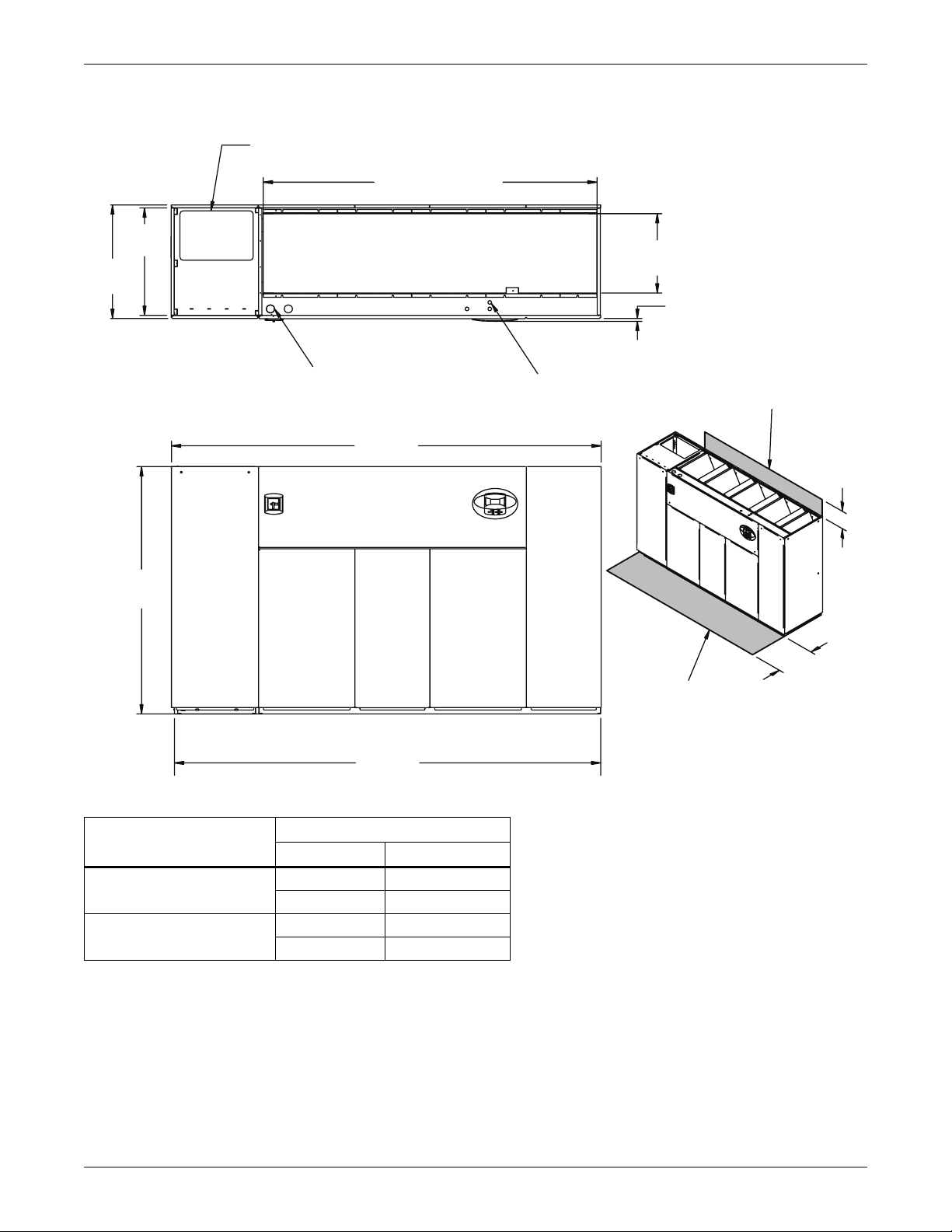
Figure 21 Cabinet and floor planning dimensions—upflow water/glycol/GLYCOOL 105kW (30 ton), all
compressors
Alternate Refrigerant
Piping Entrance
33"
(838mm)
35"
(889mm)
Alternate Condenser
Fluid Piping Entrance
High Volt Connection(s)
1-1/2"
(38mm)
76"
(1930mm)
3/4"
(19mm)
Bezels
TOP VIEW
Low Volt Connection(s)
132"
(3353mm)
Required for
condenser cleanout
Minimum required
for blower replacement
24"
(610mm)
Shaded area indicates a
2"
(51mm)
Note: Front air return unit shown. For rear return unit,
in addition to front service area shown, also include
25" (635mm) on one side of unit for access to rear
return filter box. See DPN001196.
131"
(3327mm)
FRONT VIEW
recommended minimum
clearance for component
access.
Table 18 Weights—upflow water/glycol/GLYCOOL 105kW (30 ton), all compressors
Model 105
Semi-Hermetic Compressor
Scroll or Digital Scroll
Compressor
Water/Glycol 3370 (1529)
GLYCOOL/Dual-Cool 3700 (1678)
Water/Glycol 3250 (1474)
GLYCOOL/Dual-Cool 3580 (1624)
34"
(864mm)
DPN001169
REV 0
26
Page 37

Figure 22 Floor stand dimensions—downflow, 28-42kW (8-12 ton) models
A+1-1/2"
(38mm) (with feet)
A
B
47-15/16"
(1218mm)
4-1/2"
(114mm)
Liebert DS Dimensions and Weights
33"
(838mm)
34-1/2"
(876mm)
(with feet)
1"
(25mm) TYP.
Gussets supplied
on floor stands 12" (305 mm)
tall and greater
7/8"
(23mm)
NOTE: Right side of paneled unit is flush with right side of floorstand. All other paneled sides overhang floor stand 1" (25mm).
* Leveling feet are provided with ± 1-1/2" (38mm) adjustment from nominal height C.
3"
(76mm)
Turning vane air outlet
Optional turning vane can be field-installed
in supply air discharge opening for front or
rear air discharge.
Supply air
discharge opening
16-3/4"
(425mm)
Supply air
discharge
opening
Optional turning vane
shown as front air discharge.
DPN000820
REV 2
Table 19 Floor stand and floor planning dimensions—downflow, 28-42kW (8-12 ton) models
Dimensions, in. (mm) Height, in. (mm)
Model A B C* D Turning Vane
9 (229) 4 (111)
Air-Cooled Semi-Hermetic Models and
All Water/Glycol/GLYCOOL Models
Air-Cooled Scroll Models and
Air-Cooled Digital Scroll Models
85
(2159)26(660)
72
(1829)13(330)
12 (305) 7 (187)
15 (381) 10 (264)
18 (457) 13 (340)
21 (533) 16 (416)
24 (610) 19 (492)
27
Page 38

Figure 23 Floor stand dimensions—downflow, 53-77kW (15-22 ton) models
A+1-1/2"
(38mm) (with feet)
A
B
69-3/4"
(1772mm)
4-1/2"
(114mm)
Liebert DS Dimensions and Weights
34-1/2"
(876mm)
(with feet)
33"
(838mm)
1"
(25mm) TYP.
Gussets supplied
on floor stands 12" (305 mm)
tall and greater
Turning vane air outlet
Optional turning vane can be field-installed
in supply air discharge opening for front or
rear air discharge.
NOTE: Right side of paneled unit is flush with right side of floor stand. All other paneled sides overhang floor stand 1" (25mm).
* Leveling feet are provided with ± 1-1/2" (38mm) adjustment from nominal height C.
Supply air
discharge opening
3"
(76mm)
16-3/4"
(425mm)
7/8"
(23mm)
Optional turning vane
shown as front air discharge.
DPN000930
REV 1
Supply air
discharge
opening
Table 20 Floor stand and floor planning dimensions—downflow, 53-77kW (15-22 ton) models
Dimensions, in. (mm) Height, in. (mm)
Model A B C* D Turning Vane
9 (229) 4 (111)
Air-Cooled Semi-Hermetic Models and
All Water/Glycol/GLYCOOL Models
Air-Cooled Scroll Models and
Air-Cooled Digital Scroll Models
108
(2743)26(660)
97
(2464)15(381)
12 (305) 7 (187)
15 (381) 10 (264)
18 (457) 13 (340)
21 (533) 16 (416)
24 (610) 19 (492)
28
Page 39

Figure 24 Floor stand dimensions—downflow, 105kW (30 ton) models
132-1/2"
(3366mm) (with feet)
131"
26"
(660mm)
34-1/2"
(876mm)
(with feet)
33"
(838mm)
(3327mm)
(2330mm)
91-3/4"
4-1/2"
(114mm)
16-3/4"
(425mm)
Liebert DS Dimensions and Weights
Supply air
discharge
opening
1"
(25mm) TYP.
Supply air
discharge opening
Gussets supplied
on floor stands 12" (305 mm)
tall and greater
Optional turning vane
shown as front air discharge.
7/8"
(23mm)
C*
D
3"
(76mm)
Turning vane air outlet
Optional turning vane can be field-installed
in supply air discharge opening for front or
rear air discharge.
NOTE: Right side of paneled unit is flush with right side of floorstand. All other paneled sides overhang floor stand 1" (25mm).
* Leveling feet are provided with ± 1-1/2" (38mm) adjustment from nominal height C.
DPN001059
REV 1
Table 21 Floor stand and floor planning dimensions—downflow, 105kW (30 ton) models
Height, in. (mm)
C* D turning vane
9 (229) 4 (111)
12 (305) 7 (187)
15 (381) 10 (264)
18 (457) 13 (340)
21 (533) 16 (416)
24 (610) 19 (492)
29
Page 40

Figure 25 Blower outlet and deck dimensions—upflow, 28-42kW (8-12 ton)
Liebert DS Dimensions and Weights
72" (1829mm) or 85" (2159mm ) Ref
Blow er Outlet *
E
A
B
Blower Outlet Location – Top View
Front of Unit
* Duct flange not provided
Table 22 Dimensions for upflow, 28-42kW (8-12 ton)
Models Blower Supply A B C D E
15-7/8"
(404mm)
15-7/8"
(404mm)
15-7/8"
(404mm)
15-7/8"
(404mm)
28-42kW
(8-12 ton)
Front Throw
15 x 15
Rear Throw
Front Throw
15 x 11
Rear Throw
C
35"
(889 mm)
Ref
18-5/8"
(472mm)
18-5/8"
(472mm)
14-1/2"
(368mm)
14-1/2"
(368mm)
Top of Unit
Blower Deck
D
1-1/2”
(38mm)
76"
Ref
(1930mm)
Front or Rear Throw Air Supply
DPN001120
Rev. 1
2-1/8"
(54mm)
11-5/8"
(295mm)
2-1/8"
(54mm)
11-5/8"
(295mm)
25-5/8"
(651mm)
25-5/8"
(651mm)
25-5/8"
(651mm)
25-5/8"
(651mm)
25"
(635mm)
25"
(635mm)
25"
(635mm)
25"
(635mm)
30
Page 41

Liebert DS Dimensions and Weights
Figure 26 Blower outlet and deck dimensions—upflow, 53-77kW (15-22 ton)
98" (2489mm) or 109" (2769mm)
Blower
Outlets*
F
AA
B
B
Blower Outlet Location – TOP VIEW
E
C
35"
(889mm)
Ref
Front of
Unit
* Duct Flanges Not Provided
TOP OF UNIT
1-1/2"
Blower Deck
(38mm)
D
76"
(1930mm)
Ref
Front or Rear Air Throw Supply
Table 23 Blower outlet and deck dimensions for upflow, 53-77kW (15-22 ton)
Dimensions, in. (mm)
Models Blower Supply
Front
15 x 15
53-77kW
(15-22 ton)
15 x 11
Throw
Rear Throw
Front Throw
Rear Throw
ABCDE F
15-7/8"
(404mm)
15-7/8"
(404mm)
15-7/8"
(404mm)
15-7/8"
(404mm)
18-5/8"
(472mm)
18-5/8"
(472mm)
14-11/16"
(373mm)
14-11/16"
(373mm)
2-1/8"
(54mm)
11-5/8"
(295mm)
2-1/8"
(54mm)
11-5/8"
(295mm)
27-3/4"
(705mm)
27-3/4"
(705mm)
31-3/8"
(797mm)
31-3/8"
(797mm)
DPN001191
Rev. 3
18-5/8"
(472mm)
18-5/8"
(472mm)
14-11/16"
(373mm)
14-11/16"
(373mm)
55"
(1410mm)
55"
(1410mm)
58-7/16"
(1484mm)
58-7/16"
(1484mm)
31
Page 42

Figure 27 Blower outlet and deck dimensions—upflow 105kW (30ton)
132" (3353mm)
Liebert DS Dimensions and Weights
Blower
Outlets *
A A A
B B B
Blower Outlet Location – TOP VIEW
* Duct Flanges Not Provided
Top of Unit
Blower Deck
D
G
1-1/2"
(38mm)
F
E
Front of Unit
C
35"
(889mm)
Ref
76"
(1930mm)
Ref
Front or Rear Throw Air Supply
Table 24 Blower outlet and deck dimensions—upflow 105kW (30ton)
Dimensions, in. (mm)
Models Blower SUPPLY
Front
105kW
(30 ton)
15 x 11
Throw
Rear
Throw
ABCDE FG
15-7/8
(404)
15-7/8
(404)
14-11/16
(373)
14-11/16
(373)
2-1/8
(54)
11-5/8
(295)
25-5/8
(651)
25-5/8
(651)
DPN001192
Rev. 0
30-3/4
(781)
30-3/4
(781)
54-1/2
(1384)
54-1/2
(1384)
78-1/8
(1984)
78-1/8
(1984)
32
Page 43

Figure 28 Rear return filter box dimensions
Liebert DS Dimensions and Weights
Filter
Access
Door
7-15/16"
(202mm)
76"
40"
(1930mm)
(1016mm)
38-1/4"
(971mm)
Duct Size
3-1/2"
(89mm)
A
D Duct Size
B
NOTES:
1. Filters can be accessed from either side.
2. 25" (635mm) minimum clearance provided on one side for filter access.
3. Filter boxes are shipped flat and must be field assembled.
Filter
Access
Door
C
DPN001196
Rev. 0
Table 25 Rear return filter box dimensions
Dimensions, in (mm)
Compressor Type
28-42kW (8-12 ton) Air-Cooled Scroll
and Air-Cooled Digital Scroll Models
28-42kW (8-12 ton) Semi-Hermetic
and all Water/Glycol/GLYCOOL Models
53-77kW (15-22 ton) Air-Cooled Scroll
and Air-Cooled Digital Scroll Models
53-77kW (15-22 ton) Semi-Hermetic
and all Water/Glycol/GLYCOOL Models
105kW (30 ton) All Models 2-1/4 (57) 100-1/4 (2546) 29-1/2 (749) 97-1/8 (2467) 8
AB CD# Filters
4-1/4 (108) 50-3/4 (1289) 18 (457) 47-5/8 (1210) 4
4-1/4 (108) 50-3/4 (1289) 31 (787) 47-5/8 (1210) 4
3-1/4 (83) 75-1/2 (1918) 19-1/4 (489) 72-3/8 (1838) 6
3-1/4 (83) 75-1/2 (1918) 30-1/4 (768) 72-3/8 (1838) 6
33
Page 44

Figure 29 Upflow unit plenum dimensions
Liebert DS Dimensions and Weights
Front Views – Check One (1):
With Grille
Without Grille
Left Side Views –
Check One (1):
(864mm)
With Grille
Without Grille
34"
1"
(25mm)
Panel removable for
condenser cleanout
access (water/glycol /
GLYCOOL models only)
B
Rear Views – Check One (1):
With Grille
Without Grille
Right Side Views –
A
Check One (1):
H
With Grille
76"
(1930mm)
Without Grille
Side View – Unit
With Plenum
Front View – Unit With Plenum
Notes:
1. Typical 53-77kW (15-22ton) unit orientation shown with grille plenum .
View varies by unit size and plenum selection .
2. All plenums are shipped flat and must be field assembled .
3. Optional grille plenum kits must include front or rear grille .
4. Non-grille plenums are open on the top and not designed with duct flange .
Table 26 Upflow unit plenum dimensions
Plenum Dimensions, in (mm) Grille Size, in (mm) - Nominal
A B H Front/Rear Grilles Side Grille
28-42kW (8-12 ton) Air-Cooled Scroll
and Air-Cooled Digital Scroll Models
28-42kW (8-12 ton) Semi-Hermetic
and all Water/Glycol/GLYCOOL Models
53-77kW (15-22 ton) Air-Cooled Scroll
and Air-Cooled Digital Scroll Models
53-77kW (15-22 ton) Semi-Hermetic
and all Water/Glycol/GLYCOOL Models
105kW (30 ton) All Models 105-1/4 (2673) 26-3/4 (679)
59-1/4 (1505) 13-3/4 (349)
59-1/4 (1505) 26-3/4 (679) 18 x 55 (457 x 1397) 18 x 20 (457 x 508)
82-1/4 (2089) 15-3/4 (400)
82-1/4 (2089) 26-3/4 (679) 18 x 78 (457 x 1981) 18 x 20 (457 x 508)
20
(508)
24
(610)
36
(914)
DPN001187
Rev. 0
18 x 55 (457 x 1397) 18 x 20 (457 x 508)
18 x 78 (457 x 1981) 18 x 20 (457 x 508)
(1) 18 x 20 (457 x 508)
(1) 18 x 78 (457 x 1981)
18 x 20 (457 x 508)
34
Page 45

5.0 EQUIPMENT INSPECTION AND HANDLING
Upon arrival of the unit and before unpacking it, verify that the labeled equipment matches the bill of
lading. Carefully inspect all items for damage, either visible or concealed. For initial access use a
7/32" Allen wrench for panel removal. Damage should be immediately reported to the carrier and a
damage claim filed with a copy sent to Emerson Network Power or to your sales representative.
5.1 Packaging Material
All material used to package this unit is recyclable. Please save for future use or
dispose of the material appropriately.
SAFETY INFORMATION
WARNING
!
Risk of top-heavy unit falling over. Can cause equipment damage, injury or death.
Read all of the following instructions before attempting to move the unit, lift it, remove
packaging or prepare the unit for installation.
CAUTION
!
Risk of sharp edges, splinters and exposed fasteners. Can cause personal injury.
Only properly trained personnel wearing appropriate safety headgear, gloves, shoes and
glasses should attempt to move the unit, lift it, remove packaging or prepare the unit for
installation.
Equipment Inspection and Handling
R
NOTICE
Risk of overhead interference. The unit may be too tall to fit through a doorway while on the
skid. Measure the unit and doorway heights and refer to the installation plans to verify
clearances prior to moving the unit. If the Liebert DS is too large to fit through doors, halls or
other tight spaces, the unit can be partly dismantled as detailed in 6.0 - Disassembling the
Liebert DS for Transport.
NOTICE
Risk of damage from forklift. Keep tines of the forklift level and at a height suitable to fit
below the skid and/or unit to prevent exterior and/or underside damage.
NOTICE
Risk of damage from forklift. Keep tines of the forklift level and at a height suitable to fit
below the skid and/or unit to prevent exterior and/or underside damage.
NOTICE
Risk of improper storage. Keep the Liebert DS upright, indoors and protected from dampness,
freezing temperatures and contact damage.
35
Page 46

Figure 30 Equipment recommended for handling Liebert DS
Equipment Inspection and Handling
Forklift
If possible, transport the Liebert DS with a forklift or pallet jacks. If that is not possible, use a crane
with belts or cables, slings and spreader bars.
• If using a forklift or pallet jack, make sure that the forks (if adjustable) are spread to the widest
allowable distance that will fit under the skid.
Ensure the fork length is suitable for the unit length.
• When moving the packaged Liebert DS with a forklift, lift the unit from the designated “heavy
side” of the unit no higher than 6" (152mm) off the ground. Ensure that the opposite end still
touches the ground.
• The unit is to be pulled by the forklift—If the unit must be lifted higher than 6" (152mm) great
care must be exercised: Personnel who are not directly involved in moving the unit must be kept
20' (5m) or farther from the lift point of the unit.
• Always refer to the location of the center of gravity indicators when lifting the Liebert DS (see
Figure 34).
5.2 Unpacking the Unit
Remove outer packaging when ready to install the unit.
• Remove the exterior stretch wrap packaging material from around the unit, exposing the protective corner and side packaging planks.
• Remove the corner and side packaging planks from the unit, exposing the bag over the unit.
• Remove the bag from the unit when ready to remove the skid and install the unit.
Pallet
Jack
Spreader Bars and Slings
Piano Jacks
Figure 31 Removing packaging
Step 1 Step 2 Step 3
181659P1
Rev. 5
36
Page 47

5.2.1 Removing the Unit from the Skid With a Forklift
1. Align a forklift with either the front or rear side of the unit.
WARNING
!
Risk of improper moving. Can cause equipment damage, injury or death.
Use the center of gravity indicators on the unit to determine the entry points for the tines (see
Figure 34). The center of gravity varies depending on the unit size and selected options.
The forklift’s tines must be equally spaced on either side of the center of gravity indicator.
2. Insert the tines of the forklift completely under the base of the Liebert DS.
WARNING
!
Risk of improper moving. Can cause equipment damage, injury or death.
Ensure that the tines are level, not angled up or down.
The tines must be at a height that will allow proper clearance under the unit.
Ensure the tines extend beyond the opposite side of the unit.
3. Remove the lag bolts from each bracket holding the Liebert DS to the skid.
4. Lift the unit off the skid—no more than 6" (152mm)—and remove the skid.
Figure 32 Remove the unit from the skid
Step 1 Step 2
Equipment Inspection and Handling
Step 3
Step 4
181659P1
Rev. 5
37
Page 48

5.2.2 Moving the Unit to the Installation Location with Piano Jacks
1. With the Liebert DS elevated, place two piano jacks into position—one at either end of the unit.
2. Lower the unit to a height suitable for the piano jacks and place protective material between the
Liebert DS and the piano jacks.
3. Secure the unit to the piano jacks and remove the forklift.
4. Use the piano jacks to move the unit for installation.
Figure 33 Moving the unit to its installation location
Step 1
Step 2
Equipment Inspection and Handling
5.2.3 Removing Piano Jacks
1. Lower the unit as much as the piano jacks will allow.
2. Undo all strapping holding the piano jacks to the unit.
3. Use a pry bar or similar device to lift one end of the unit just enough to allow removal of the piano
jack from that end.
4. Repeat Step 3 to remove the piano jack on the opposite end.
5. Remove all material that might have been used to protect the unit from the piano jacks and
strapping.
Step 3
181659P1
Rev. 5
38
Page 49

5.2.4 Removing Liebert DS from Skid Using Rigging
WARNING
!
Risk of improper moving. Can cause equipment damage, injury or death.
Use the center of gravity indicators (see Figure 34) on the unit to determine the position of
the slings. The center of gravity varies depending on the unit size and selected options.
The forklift’s tines must be equally spaced on either side of the center of gravity indicator.
1. Space the slings equidistant on either side of the center of gravity indicator (see Figure 34).
Figure 34 Locate center of gravity marker and place slings
Equipment Inspection and Handling
Lifting
Sling
Illustration shows one possible center of gravity.
The center of gravity on the Liebert DS varies with
the options and the model’s size.
Equal
Distance
2. Place the slings between the bottom rails of the Liebert DS and the top of the skid.
Equal
Distance
Lifting
Sling
181659P1
Rev. 5
NOTE
Unit is shown without packaging. These instructions may be applied with the outer packaging
in place.
3. Use spreader bars or a similar device and padding to ensure the Liebert DS will not be damaged
when the unit is lifted. Lifting will force the slings toward the Liebert DS and the slings may
damage the unit unless it is properly protected.
4. Remove the lag bolts from the bracket securing the Liebert DS to the shipping skid.
5. Remove the brackets.
NOTE
Depending on final installation location, the skid may need to remain under the unit.
Therefore, the lag bolts and brackets would not yet be removed.
6. Lift the Liebert DS off the skid.
7. Move the skid from under the unit.
39
Page 50

Figure 35 Using rigging to lift Liebert DS off skid
Lifting
Sling
Equipment Inspection and Handling
Lifting
Sling
Equal
Distance
Equal
Distance
40
181659P1
Rev. 5
Page 51

5.3 Semi-Hermetic Compressor Spring Isolation System
Shipping blocks under all semi-hermetic compressors must be removed and the springs must be
adjusted before startup.
1. Loosen nuts at each of the four compressor feet and remove the two shipping blocks.
2. Beginning with one compressor foot, retighten nut until the washer under the nut can no longer
be rotated by finger.
3. Loosen the nut half a turn. The washer will be slightly loose.
4. Repeat for remaining feet and recheck all when done
5.4 Placing the Unit on a Floor Stand
Liebert Floor Stand—Ensure that the optional turning vane is installed in the floor stand (if
included) prior to placing the unit. Refer to the floor stand installation sheet, 182278P1, located inside
the floor stand package. Lower the unit onto the floor stand. Refer to Detail A in Figure 36. Be sure
to align the welded tabs on top of the floor stand with the inside of the unit frame base.
Figure 36 Setting the unit on a floor stand
Welded Tab
Equipment Inspection and Handling
A
DETAIL A
A
Liebert Floor Stand
(front discharge shown)
Upflow rear return configurations use a filter box that attaches to the back of the Liebert DS. Refer to
rear return installation sheet, 187230P1, located inside rear-return filter box package.
41
Page 52

Disassembling the Liebert DS for Transport
6.0 DISASSEMBLING THE LIEBERT DS FOR TRANSPORT
The Liebert DS has a modular frame construction that allows separating the unit into three sections.
Each of these sections is more easily maneuvered through tight spaces or placed in small elevators.
A qualified service technician with the required tools and recommended assistance can disassemble
an air-cooled unit in about four hours, assuming refrigerant evacuation is not required.
This procedure requires four or more people for lifting the filter and electric box assembly on downflow units and for lifting the blower and electric box assembly on upflow units.
WARNING
!
Risk of explosive discharge from high-pressure refrigerant. Can cause injury or death.
This unit contains fluids and/or gases under high pressure. Relieve pressure before working
with piping, compressors or other internal components.
WARNING
!
Risk of top heavy unit falling over. Improper handling can cause equipment damage, injury,
or death.
Read all instructions before attempting to move or lift unit. Installation and service of this
equipment should be done only by properly trained and qualified personnel who have been
specially trained in the installation of air conditioning equipment.
CAUTION
!
Risk of sharp edges and heavy parts. Can cause personal injury.
Only properly trained and qualified personnel wearing appropriate safety headgear, gloves,
shoes and glasses should attempt to move, lift, remove packaging from or prepare unit for
installation.
NOTICE
Disassembling this unit requires substantial work, including reclaiming refrigerant and
charging the unit, cutting and brazing refrigerant lines, cutting and brazing water lines,
disconnecting and reconnecting electrical lines and moving heavy, bulky equipment. One
member of the crew disassembling the unit must be qualified in wiring, brazing and
refrigeration.
Improperly disassembling or reassembling the Liebert DS may affect warranty.
6.1 Required Equipment
•Piano jacks
• Stepladder for downflow units
• Refrigeration tools
6.2 Disassembly—Downflow Units
For detailed views of downflow units, see Figures 37 through 45.
1. Remove the unit from its shipping skid before beginning (refer to 5.2 - Unpacking the Unit).
2. Remove all panels except the top front accent.
3. Remove all filters. This allows access to the screws for metal plate blocking off the top coil and
removal of the filter plate.
4. All wires are hot-stamped and all circuit board connectors are lettered to ease connection. Some
cable ties must be cut and replaced. Refer to the unit’s wiring schematic on the unit’s deadfront
panel for details.
42
Page 53

Disassembling the Liebert DS for Transport
NOTICE
Do not lay the compressor section on its side. It must remain upright. The coil section also
must remain upright.
5. Label the three quick-connect plugs from the compressor compartment and disconnect them.
6. Disconnect the compressor wire harness, including the crankcase heater wires, if present, from
the contactor in the electric box.
7. Pull the conduit and wires into the compressor compartment.
8. Disconnect the fan motor wire harness from the bottom of the contactor in the electric box.
9. Pull the conduit and wires into the bottom section of the Liebert DS.
10. Reheat—Optional Component
a. Disconnect the reheat wire harness from the bottom of the contactor in the electric box.
b. Unplug the low-voltage quick connect for the reheat safety wires.
c. Pull the conduit and wires into the unit’s blower and coil assembly section.
11. Humidifier—Optional Component
a. Disconnect the humidifier wire harness from the bottom of the contactor in the electric box.
b. Remove the humidifier low-voltage connections 35-5 and 35-6 by disconnecting the
quick-connect plug.
c. Disconnect 35-3 and 35-4 from the control board.
d. Pull the conduit and wires into the unit’s blower and coil assembly section.
12. Condensate Pump—Optional Component
a. Disconnect the condensate pump’s high-voltage wiring harness.
b. Remove the low-volt wires from terminal strips #24 and #55.
c. Pull the conduit and wires into the unit’s blower and coil assembly section.
13. GLYCOOL/Dual-Cool—Optional Component
a. On units with an actuator, unplug the valve actuator harness at the actuator and pull the
wire harness into the electric box.
b. Disconnect the glycol sensor from the control board and pull it into the unit’s blower and coil
assembly section.
14. Disconnect the air sail switch wires and pull them into the electric box.
15. Smoke Detector—Optional Component
a. Remove the smoke detector cover.
b. Remove the plug connector from the smoke detector and pull it into electric box.
c. Remove the wires from terminal strips #91, 92, 93 and route them into the smoke detector
box.
d. Remove the sensing tube from top of the smoke detector.
The wand and tube will remain attached to filter and electric box assembly.
16. Close the electric box cover and the accent panel.
17. Remove the pull bar that supports the accent panel from the left end of unit, otherwise it will fall
out when the compressor section is removed.
18. Evacuate and recover all refrigerant from the Liebert DS.
Air-cooled units are shipped with a nitrogen holding charge. Water, glycol and GLYCOOL units
are factory-charged with refrigerant. Refer to 8.0 - Piping for piping guidelines and to the
ASHRAE Refrigeration Handbook for general, good-practice refrigeration piping.
NOTICE
Risk of compressor oil contamination with moisture.
Emerson recommends front-seating the compressor service valves. Front-seating the valves
keeps the nitrogen or refrigerant charge in the compressor and prevents moisture from
contaminating the compressor oil. This is particularly important with units using R-407C
refrigerant.
43
Page 54

19. Cut the insulation and pull it back from the piping.
20. Cut the refrigerant piping with a tubing cutter; if there is no Schrader fitting, let the nitrogen
bleed out before cutting all the way through the pipe.
NOTE
Emerson does not recommend unsweating refrigerant connections.
21. Unsweat or cut all copper water pipes that interconnect unit sections.
22. Immediately cap and seal all piping that has been cut, including the suction and liquid lines, as
well as the fluid piping on GLYCOOL and dual-cool units.
6.2.1 Remove the Compressor Assembly
1. Secure the compressor wire harness to the compressor assembly.
2. Remove the 10 thread-cutting bolts holding the compressor section assembly to the filter and
electric box assembly and the blower and coil assembly.
There are five bolts in the front, four in the back and one on the top at the middle of the unit.
a. Begin removing bolts at the bottom of the unit and progress toward the top. Use this method
for the front and back bolts.
b. Stabilize the compressor section before removing the top, middle bolt.
NOTICE
The compressor section is top-heavy and has a small base. It must remain upright. Do not lay
the compressor section on its side during or after removing it from the Liebert DS. Do not
remove shipping blocks from semi-hermetic compressors until the Liebert DS is fully
reassembled and ready for installation.
Disassembling the Liebert DS for Transport
NOTE
Emerson recommends using piano jacks when moving this section.
6.2.2 Remove the Filter and Electric Box Assembly
1. Using a stepladder to reach the top of the Liebert DS, remove the filter support plate; it is
attached to the filter and electric box assembly with two screws, one on each end.
2. Remove tags from the Schrader fittings on top of the coil headers. Retain the tags for replacement
during reassembly.
3. Remove 16 screws, (8) on each side, from the evaporator top cover plate to coil assembly. Coil top
blocker will remain with top section for rigidity.
4. Remove coil access plates from the left side of the Liebert DS.
5. Remove the four thread-cutting bolts securing the filter and electric box assembly to the blower
and coil assembly. There are two on the left and two on the right.
6. Separate the unit sections with caution.
NOTICE
Risk of improper handling.
• The filter and electric box section should be moved forward and set on the floor.
• Make sure to lift the coil plate over the Schrader fittings on the headers. Emerson
recommends using four people to remove this section. Special care is required when moving
this section because the legs are not designed to withstand strong shocks.
• The blower and coil assembly must remain upright. The coil is not secured to the blower
and coil assembly.
• Secure the coil to the bottom section with straps or a similar method before moving the
section.
7. Move each section of the Liebert DS to the installation location.
44
Page 55

6.3 Reassembly—Downflow Units
1. Replace the top section.
Make sure to clear the Schrader valves on the coil header.
2. Reconnect the filter and electric box assembly to the blower and coil assembly using threadcutting bolts.
Torque the bolts to 225 in-lb. (25Nm)
3. Reattach the evaporator top cover plate; there are eight screws on each side.
4. Reattach the filter support plate to the filter and electric box assembly; there is one screw on each
side.
5. Reattach the tags to the Schrader fittings on top of the coil headers.
6. Replace the compressor section.
Insert all compressor thread-cutting bolts before tightening any of the bolts.
7. Reinstall the pull bar to support the accent panel.
8. Reattach the low-voltage plugs in the compressor section.
9. Reconnect the wiring for the compressor, fan motor, reheat, humidifier, condensate pump, smoke
detector and air sail switch.
10. Reattach the sensing tube to the top of the smoke detector.
11. On GLYCOOL and dual-cool units, reattach the plug connection at the actuator and reroute the
sensor wire back through the electric box and onto the control board.
6.3.1 Reconnecting Piping, Charging and Replacing Panels
1. Piping must be reassembled in accordance with local codes.
2. Move insulation and plastic bushings away from the brazing area.
3. Wrap piping with wet cloths. Use copper fittings where required.
4. Refer to 8.0 - Piping for piping guidelines and to the ASHRAE Refrigeration Handbook for
general, good-practice refrigeration piping.
5. Open the service valves on the compressor.
6. Reinsert the plastic bushings.
7. Charge the Liebert DS with refrigerant; see the unit’s nameplate for the proper charge.
8. Reinstall the galvanized panels on the left side of the coil.
9. Replace the filters.
10. Replace the panels.
Disassembling the Liebert DS for Transport
45
Page 56

6.4 Reassembly Checklist
___ 1. Thread-cutting bolts reconnected and torqued to 225 in-lb. (25Nm)
___ 2. Top cover plate attached to coil
___ 3. Filter plate attached
___ 4. High-voltage wires connected to proper contactors:
___ a. Compressor
___ b. Fan motor
___ c. Reheat, if applicable
___ d. Humidifier, if applicable
___ e. Condensate pump, if applicable
___ 5. Low-voltage wires connected
___ a. Actuator
___ b. Terminal strip
___ c. Plug connections
___ d. Smoke detector, if applicable
___ 6. Coil access plates on right and left replaced
___ 7. Water lines brazed
___ 8. Suction and liquid refrigerant lines brazed
___ 9. Unit recharged
___ 10. Filters replaced
___ 11. Panels replaced
Disassembling the Liebert DS for Transport
46
Page 57

Disassembling the Liebert DS for Transport
Figure 37 Component dimensions—downflow, air-cooled, 28-42kW (8-12 ton), semi-hermetic compressor
models
Filter & Electric
Box Assembly
39"
(991mm)
Compressor Assembly
Blower & Coil
Assembly
76"
(1930mm)
(940mm)
33"
(838mm)
26"
(660mm)
59" (1499mm)
85" (2159mm)
Assembled Length
NOTES: Drawing views are simplified with panels removed to show overall dimensions.
See disassembly and handling instructions in installation manual.
Table 27 Component weights—downflow, air-cooled, 28-42kW (8-12 ton), semi-hermetic
Dry Weight, Approximate, Including Panels, lb (kg)
Component Air-Cooled Dual-Cool
Compressor Assembly 800 (364) 800 (364)
Filter & Electric Box Assembly 210 (96) 210 (96)
Blower & Coil Assembly 770 (350) 920 (418)
76"
(1930mm)
Assembled
Height
60-3/16"
(1529mm)
37"
DPN000801
Rev. 1
47
Page 58

Disassembling the Liebert DS for Transport
Figure 38 Component dimensions—downflow, air-cooled, 28-42kW (8-12 ton), scroll/digital scroll
compressor models
Filter & Electric
Box Assembly
39"
(991mm)
Compressor Assembly
Blower & Coil
Assembly
(1930mm)
Assembled
Height
76"
76"
(1930mm)
60-3/16"
(1529mm)
37"
(940mm)
33"
(838mm)
13"
(330mm)
59" (1499mm)
72" (1829mm)
Assembled Length
NOTES: Drawing views are simplified with panels removed to show overall dimensions.
See disassembly and handling instructions in installation manual.
DPN000802
Rev. 1
Table 28 Component weights—downflow, air-cooled, 28-42kW (8-12 ton), scroll/digital scroll
Dry Weight, Approximate, lb. (kg)
Component Air-Cooled Dual-Cool
Compressor Assembly 490 (223) 490 (223)
Filter & Electric Box Assembly 210 (96) 210 (96)
Blower & Coil Assembly 770 (350) 920 (418)
48
Page 59

Disassembling the Liebert DS for Transport
Figure 39 Component dimensions—downflow, water/glycol/GLYCOOL, 28-42kW (8-12 ton), all compressor
models
Filter & Electric
Box Assembly
39"
(991mm)
Compressor Assembly
Blower & Coil
Assembly
76"
(1930mm)
60-3/16"
(1529mm)
37"
(940mm)
33"
(838mm)
26"
(660mm)
59" (1499mm)
85" (2159mm)
Assembled Length
NOTES: Drawing views are simplified with panels removed to show overall dimensions.
See disassembly and handling instructions in installation manual.
DPN000899
Rev. 1
Table 29 Component weights—downflow, water/glycol/GLYCOOL, 28-42kW (8-12 ton), all
Dry Weight, Approximate, Including Panels, lb (kg)
Semi-Hermetic Compressor Scroll or Digital Scroll Compressor
Component
Compressor Assembly 950 (432) 950 (432) 800 (364) 800 (364)
Filter & Electric Box Assembly 210 (96) 210 (96) 210 (96) 210 (96)
Blower & Coil Assembly 770 (350) 920 (418) 770 (350) 920 (418)
Water/Glycol GLYCOOL/Dual-Cool Water/Glycol GLYCOOL/Dual-Cool
76"
(1930mm)
Assembled
Height
49
Page 60

Disassembling the Liebert DS for Transport
Figure 40 Component dimensions—downflow, air-cooled, 53-77kW (15-22 ton), semi-hermetic
compressor models
Filter & Electric
Box Assembly
39"
(991mm)
Compressor Assembly
Blower & Coil
Assembly
76"
(1930mm)
37"
(940mm)
33"
(838mm)
26"
(660mm)
82" (2083mm)
108" (2743mm)
Assembled Length
NOTES: Drawing views are simplified with panels removed to show overall dimensions.
See disassembly and handling instructions in installation manual.
DPN000926
Rev. 2
Table 30 Component weights—downflow, air-cooled, 53-77kW (15-22 ton), semi-hermetic
Dry Weight, Approximate, Including Panels, lb (kg)
Component
Compressor Assembly 970 (441) 970 (441)
Filter & Electric Box Assembly 250 (114) 250 (114)
Blower & Coil Assembly 1230 (560) 1410 (641)
Air-Cooled Dual-Cool
76"
(1930mm)
Assembled
Height
59-7/16"
(1509mm)
50
Page 61

Disassembling the Liebert DS for Transport
Figure 41 Component dimensions—downflow air-cooled, 53-77kW (15-22 ton), scroll/digital scroll
compressor models
Filter & Electric
Box Assembly
39"
(991mm)
Compressor Assembly
Blower & Coil
Assembly
76"
(1930mm)
33"
(838mm)
15"
(381mm)
82" (2083mm)
97" (2464mm)
59-7/16"
(1509mm)
37"
(940mm)
Assembled Length
NOTES: Drawing views are simplified with panels removed to show overall dimensions.
See disassembly and handling instructions in installation manual.
DPN000927
Rev. 2
Table 31 Component weights—downflow, air-cooled, 53-77kW (15-22 ton), scroll/digital scroll
Dry Weight, Approximate, Including Panels, lb (kg)
Component
Compressor Assembly 540 (246) 540 (246)
Filter & Electric Box Assembly 250 (114) 250 (114)
Blower & Coil Assembly 1230 (560) 1410 (641)
Air-Cooled Dual-Cool
76"
(1930mm)
Assembled
Height
51
Page 62

Disassembling the Liebert DS for Transport
Figure 42 Component dimensions—downflow water/glycol, GLYCOOL, 53-77kW (15-22 ton), all
compressor models
Filter & Electric
Box Assembly
39"
(991mm)
Compressor Assembly
Blower & Coil Assembly
(1930mm)
Assembled Height
76"
76"
(1930mm)
(1509mm)
37"
(940mm)
33"
(838mm)
26"
(660mm)
108" (2743mm)
Assembled Length
82"
(2083mm)
NOTES: Drawing views are simplified with panels removed to show overall dimensions.
See disassembly and handling instructions in installation manual.
Table 32 Component weights—downflow water/glycol, GLYCOOL, 53-77kW (15-22 ton), all
Semi-Hermetic Compressor Scroll Compressor
GLYCOOL
Water/Glycol
Liebert DS Section
Compressor Assembly 1270 (578) 1270 (578) 840 (382) 840 (382)
Filter and Electric Box Assembly 250 (114) 250 (114) 250 (114) 250 (114)
Blower & Coil Assembly 1230 (560) 1410 (641) 1230 (560) 1410 (641)
lb (kg)
Dual-Cool
lb (kg)
Water/Glycol
lb (kg)
GLYCOOL
Dual-Cool
lb (kg)
59-7/16"
DPN000932
Rev. 1
52
Page 63

Disassembling the Liebert DS for Transport
Figure 43 Component dimensions—downflow, air-cooled, 105kW (30 ton), semi-hermetic compressor
models
Filter and Electric Box Assembly
39"
(991mm)
41-11/16"
(1059mm)
Compressor Assembly
1930mm
Assembled
59-7/16"
(1510mm)
76"
(1930mm)
33"
(838mm)
26"
(660mm)
Blower and Coil Assembly
131" (3327mm)
Assembled Length
105"
(2667mm)
37"
(940mm)
DPN001057
Rev. 0
Table 33 Component weights—downflow, air-cooled, 105kW (30 ton), semi-hermetic compressors
Dry Weight, lb (kg) Approximate (Includes Panels)
Component
Compressor Assembly 950 (432) 950 (432)
Filter & Electric Box Assembly 270 (123) 270 (123)
Blower & Coil Assembly 1820 (827) 2180 (991)
Air Cooled Dual Cool
76"
Height
53
Page 64

Disassembling the Liebert DS for Transport
Figure 44 Component dimensions—downflow, air-cooled, 105kW (30 ton), scroll compressor models
Filter & Electric
Box Assembly
41-11/16"
(1059mm)
39"
(991mm)
Compressor Assembly
Blower & Coil Assembly
76"
(1930mm)
33"
(838mm)
NOTES: Drawing views are simplified with panels removed to show overall dimensions.
See disassembly and handling instructions in installation manual.
26"
(660mm)
131" (3327mm)
Assembled Length
105"
(2667mm)
37"
(940mm)
1930mm
Assembled Height
59-7/16"
(1510mm)
DPN001058
Rev. 0
Table 34 Component weights—downflow, air-cooled, 105kW (30 ton), scroll compressor models
Dry Weight, Approximate, Including Panels, lb (kg)
Component
Compressor Assembly 830 (377) 830 (377)
Filter & Electric Box Assembly 270 (123) 270 (123)
Blower & Coil Assembly 1820 (827) 2180 (991)
Air-Cooled Dual-Cool
76"
54
Page 65

Disassembling the Liebert DS for Transport
Figure 45 Component dimensions—downflow, water/glycol/GLYCOOL, 105kW (30 ton), all compressor
models
Filter & Electric
Box Assembly
39"
(991mm)
41-11/16"
(1059mm)
Compressor Assembly
(1930mm)
Blower & Coil Assembly
76"
(1930mm)
33"
(838mm)
NOTES: Drawing views are simplified with panels removed to show overall dimensions.
See disassembly and handling instructions in installation manual.
26"
(660mm)
105" (2667mm)
131" (3327mm)
Assembled Length
37"
(940mm)
Assembled
Height
59-7/16"
(1510mm)
DPN001060
Rev. 0
Table 35 Component weights—downflow, water/glycol/GLYCOOL, 105kW (30 ton), all compressor
models
Dry Weight, Approximate, Including Panels, lb (kg)
Semi-Hermetic Compressor Scroll Compressor
Component
Compressor Assembly 1320 (600) 1320 (600) 1200 (545) 1200 (545)
Filter & Electric Box Assembly 270 (123) 270 (123) 270 (123) 270 (123)
Blower & Coil Assembly 1820 (827) 2180 (991) 1820 (827) 2180 (991)
Water/Glycol GLYCOOL/Dual-Cool Water/Glycol GLYCOOL/Dual-Cool
76"
55
Page 66

6.5 Disassembly—Upflow Units
For detailed views of upflow units, see Figures 46 through 54.
1. Remove the unit from its skid.
2. Remove all panels except top front accent.
3. Remove all filters on front return units. This allows easier access to items located in the filter and
coil assembly.
4. All wires are hot stamped and all circuit board connectors are lettered for easy replacement.
Cable ties will need to be cut and replaced as necessary. Reference unit wiring schematic on
deadfront panel for details.
5. Label the (3) quick connect plugs from the compressor compartment, and disconnect them.
6. Disconnect compressor wire harness, including crankcase heater wires, if applicable, from
contactor in electric box. Pull conduit and wires into compressor compartment.
7. Reheat (optional component): Disconnect reheat wire harness from bottom of contactor in
electric box. Unplug low-voltage quick connect for reheat safety wires. Pull conduit and wires into
filter and coil assembly section of unit.
8. Humidifier (optional component): Disconnect humidifier wire harness from bottom of
contactor in electric box. Remove humidifier low-voltage connections 35-5 and 35-6 by
disconnecting quick connect plug, disconnect 35-3 and 35-4 from control board. Pull conduit and
wires into filter and coil assembly section of unit.
9. Condensate pump (optional component): Disconnect condensate pump high-voltage wire
harness. Remove low volt wires from terminal strip #24 and #55. Pull conduit and wires into filter
and coil assembly section of unit.
10. Glycool/Dual-Cool (optional component): On units with actuator, unplug valve actuator
harness at actuator and pull wire harness into electric box. Disconnect glycol sensor from control
board and pull into filter and coil assembly section of unit.
11. Smoke detector (optional component): For units with smoke detector, remove cover on smoke
detector. Remove plug connector from smoke detector and pull into electric box. Remove wires
from terminal strip #91, 92, 93 and route the wires to the smoke detector box. Remove the sensing
tube from the bottom of the plastic elbow.
12. Filter Clog Switch: Disconnect both tubes from the filter clog switch. Pull both of the tubes into
the electric box.
13. Close the electric box cover and the accent panel.
14. Remove the pull bar that supports the accent panel from left end of unit, otherwise it will fall out
when the compressor section is removed.
15. Evacuate and recover all refrigerant from the unit.
Air-cooled units contain a nitrogen holding charge. Water, glycol and GLYCOOL units are factory
charged with refrigerant. Refer to 8.0 - Piping for piping guidelines and to the ASHRAE Refrigeration Handbook for general, good-practice refrigeration piping.
Disassembling the Liebert DS for Transport
NOTICE
Risk of compressor oil contamination with moisture.
Emerson recommends front-seating the compressor service valves. Front-seating the valves
keeps the nitrogen or refrigerant charge in the compressor and prevents moisture from
contaminating the compressor oil. This is particularly important with units using R-407C
refrigerant.
16. Cut and pull back insulation from piping.
17. Cut the refrigerant piping with a tubing cutter; if there is no Schrader fitting, let the nitrogen
bleed out before cutting all the way through the pipe.
NOTE
Emerson does not recommend unsweating refrigerant connections.
18. Unsweat or cut all copper water pipes that interconnect unit sections.
56
Page 67

19. Immediately cap off and seal all piping that has been cut, including the suction and liquid lines,
the humidifier supply line and the condensate discharge line (if applicable), as well as fluid piping
on GLYCOOL and dual-cool units.
6.5.1 Remove Compressor Assembly
1. Secure the compressor wire harness to the compressor assembly.
2. Remove the 10 thread-cutting bolts holding compressor section together.
a. Begin removing bolts at the bottom of the Liebert DS and progress toward the top. Use this
method for the front and back bolts.
b. Stabilize the compressor section before removing the top, middle bolt.
NOTICE
The compressor section is top-heavy and has a small base. It must remain upright. Do not lay
the compressor section on its side during or after removing it from the Liebert DS. Do not
remove the shipping blocks from the semi-hermetic compressors until the Liebert DS is fully
reassembled and ready for installation.
NOTE
Emerson recommends using piano jacks when moving this section.
6.5.2 Remove Blower and Electric Box Assembly
1. Remove the motor access plate from right end of unit.
This will provide a place to grasp the blower and electric box assembly and move it.
Remove the coil access plates on the left side of the unit for clearance when brazing the suction
and discharge lines.
2. Remove the thread-cutting bolts holding the unit sections together; there are four on the left and
four on the right.
3. Separate the unit sections with caution.
Disassembling the Liebert DS for Transport
NOTICE
Risk of improper handling. May cause damage to the Liebert DS.
• The blower and electric box assembly should be moved forward and set on the floor.
• Emerson recommends using four people to remove this section.
• The motor end will be significantly heavier than the other end.
• The filter and coil assembly must remain upright. The coil is not secured to the filter and
coil assembly.
• Secure the coil to the bottom section with straps or a similar means before moving the
section.
4. Move each section of the Liebert DS to the installation location.
57
Page 68

6.6 Reassembly—Upflow Unit
1. Reattach the top section using thread-cutting bolts; there are four on each side.
Torque the bolts to 225 in-lb (25Nm).
2. Reinstall the motor access plate.
Do not replace the left end coil access plates until brazing is finished.
3. Reattach the compressor section. Insert all compressor thread-cutting bolts before tightening
them all down.
4. Reinstall the pull bar to support the accent panel.
5. Reinstall the low-voltage plugs in the compressor section.
6. Rewire the compressor, reheat, humidifier, condensate pump and smoke detector, if applicable.
7. Reattach the sensing tube to the blower inlet.
8. Reattach the plug connection at the actuator and reroute the sensor back through electric box and
onto control board, on GLYCOOL and dual-cool units.
9. Piping must be reassembled in accordance with local codes.
10. Move the insulation and plastic bushings away from the brazing area.
11. Wrap the piping with wet cloths. Use copper fittings where required.
12. Refer to 8.0 - Piping for piping guidelines and to the ASHRAE Refrigeration Handbook for
general, good-practice refrigeration piping.
13. Open service valves on compressor.
14. Reinsert plastic bushings.
15. Charge the Liebert DS with refrigerant; see the unit’s nameplate for the proper charge.
16. Replace the galvanized panels on the left side of the coil.
17. Replace the filters.
18. Replace the panels.
Disassembling the Liebert DS for Transport
6.7 Reassembly Checklist
___ 1. Thread-cutting bolts reconnected at a torque specification of 225 in-lb (25Nm).
___ 2. High-voltage wires connected to proper contactors:
___ a. compressor
___ b. reheat, if applicable
___ c. humidifier, if applicable
___ d. condensate pump, if applicable
___ 3. Low-voltage wires connected:
___ a. actuator
___ b. terminal strip
___ c. plug connections
___ d. smoke detector, if applicable
___ 4. Coil access plates on left side replaced
___ 5. Motor access plate on right side replaced
___ 6. Water lines brazed
___ 7. Suction and liquid refrigerant lines brazed
___ 8. Unit recharged
___ 9. Filters replaced
___ 10. Panels replaced
58
Page 69

Disassembling the Liebert DS for Transport
Figure 46 Component dimensions—upflow, air-cooled, 28-42kW (8-12 ton), semi-hermetic compressor
models
Blower & Electric Box Assembly
31-1/4"
(794mm)
Compressor Assembly
76"
(1930mm)
Filter & Coil
Assembly
76"
(1930mm)
33"
(838mm)
NOTES: Drawing views are simplified with panels removed to show overall dimensions.
See disassembly and handling instructions in installation manual.
26"
(660mm)
85"
Assembled Length
(2159mm)
59"
(1499mm)
Assembled
Height
45-13/16"
(1163mm)
DPN001171
Rev. 0
Table 36 Component weights—upflow, air-cooled, 28-42kW (8-12 ton), semi-hermetic compressor
models
Dry Weight, Approximate, Including Panels, lb (kg)
Component Air-Cooled Dual-Cool
Compressor Assembly 800 (364) 800 (364)
Blower & Electric Box Assembly 510 (231) 510 (231)
Filter & Coil Assembly 520 (236) 670 (304)
59
Page 70

Disassembling the Liebert DS for Transport
Figure 47 Component dimensions—upflow, air-cooled, 28-42kW (8-12 ton), scroll/digital scroll
compressor models
Blower & Electric
Box Assembly
31-1/4"
(794mm)
Compressor Assembly
76"
(1930mm)
Assembled
Filter & Coil Assembly
Height
76"
(1930mm)
45-13/16"
(1163mm)
33"
(838mm)
13"
(330mm)
59"
(1499mm)
72" (1829mm)
Assembled Length
NOTES: Drawing views are simplified with panels removed to show overall dimensions.
See disassembly and handling instructions in installation manual.
DPN001172
Rev. 0
Table 37 Component weights—upflow, air-cooled, 28-42kW (8-12 ton), scroll/digital scroll compressor
models
Dry Weight, Approximate, Including Panels, lb (kg)
Component
Compressor Assembly 490 (223) 490 (223)
Blower & Electric Box Assembly 510 (231) 510 (231)
Filter & Coil Assembly 520 (236) 670 (304)
Air-Cooled Dual-Cool
60
Page 71

Disassembling the Liebert DS for Transport
Figure 48 Component dimensions—upflow, water/glycol/GLYCOOL, 28-42kW (8-12 ton), all compressor
models
Blower & Electric
Box Assembly
31-1/4"
(794mm)
Compressor Assembly
76"
(1930mm)
Filter & Coil Assembly
Assembled
Height
76"
(1930mm)
45-13/16"
(1163mm)
33"
(838mm)
26"
(660mm)
59"
(1499mm)
85" (2159mm)
Assembled Length
NOTES: Drawing views are simplified with panels removed to show overall dimensions.
See disassembly and handling instructions in installation manual.
DPN001173
Rev. 0
Table 38 Component weights—upflow, water/glycol/GLYCOOL, 28-42kW (8-12 ton), all compressor
models
Dry Weight, Approximate, Including Panels, lb (kg)
Semi-Hermetic Compressor Scroll Compressor
Component
Compressor Assembly 950 (432) 950 (432) 800 (364) 800 (364)
Blower & Electric Box Assembly 510 (231) 510 (231) 510 (231) 510 (231)
Filter & Coil Assembly 520 (236) 670 (304) 520 (236) 670 (304)
Water/Glycol GLYCOOL/Dual-Cool Water/Glycol GLYCOOL/Dual-Cool
61
Page 72

Disassembling the Liebert DS for Transport
Figure 49 Component dimensions—upflow, air-cooled, 53-77kw (15-22 ton), semi-hermetic compressor
models
Blower & Electric
Box Assembly
31-1/4"
(794mm)
Compressor Assembly
(1930mm)
Filter & Coil Assembly
Assembled
Height
76"
(1930mm)
45-13/16"
(1163mm)
33"
(838mm)
26"
(660mm)
82"
(2083mm)
108" (2743mm) Assembled Length
NOTES: Drawing views are simplified with panels removed to show overall dimensions.
See disassembly and handling instructions in installation manual.
DPN001209
Rev. 0
Table 39 Component weights—upflow air-cooled 53-77kw (15-22 ton), semi-hermetic compressor
models
Dry Weight, Approximate, Including Panels, lb (kg)
Component
Compressor Assembly 970 (441) 970 (441)
Blower & Electric Box Assembly 770 (349) 770 (349)
Filter & Coil Assembly 760 (345) 940 (426)
Air-Cooled Dual-Cool
76"
62
Page 73

Disassembling the Liebert DS for Transport
Figure 50 Component dimensions—upflow, air-cooled, 53-77kw (15-22 ton), scroll/digital scroll
compressor models
Blower & Electric
Box Assembly
31-1/4"
(794mm)
Compressor Assembly
76"
(1930mm)
Assembled
Filter & Coil
Assembly
76"
(1930mm)
33"
(838mm)
NOTES: Drawing views are simplified with panels removed to show overall dimensions.
See disassembly and handling instructions in installation manual.
15"
(381mm)
82" (2083mm)
97" (2464mm) Assembled Length
DPN001210
Rev. 0
Height
45-13/16"
(1163mm)
Table 40 Component weights—upflow, air-cooled, 53-77kw (15-22 ton), scroll /digital scroll compressor
models
Dry Weight, Approximate, Including Panels, lb (kg)
Component
Compressor Assembly 540 (246) 540 (246)
Blower & Electric Box Assembly 770 (349) 770 (349)
Filter & Coil Assembly 760 (345) 940 (426)
Air-Cooled Dual-Cool
63
Page 74

Disassembling the Liebert DS for Transport
Figure 51 Component dimensions—upflow water/glycol/GLYCOOL 53-77kw (15-22 ton), all compressor
models
Blower & Electric
Box Assembly
31-1/4"
(794mm)
Compressor Assembly
(1930mm)
Assembled
Filter & Coil
Assembly
76"
(1930mm)
33"
(838mm)
NOTES: Drawing views are simplified with panels removed to show overall dimensions.
See disassembly and handling instructions in installation manual.
26"
(660mm)
108" (2743mm) Assembled Length
82" (2083mm)
DPN001211
Rev. 0
Height
45-13/16"
(1163mm)
Table 41 Component weights—upflow water/glycol/GLYCOOL, 53-77kW (15-22 ton) all compressor
models
Dry Weight, Approximate, Including Panels, lb (kg)
Semi-Hermetic Compressor Scroll or Digital Scroll Compressor
Component
Compressor Assembly 1270 (578) 1270 (578) 840 (382) 840 (382)
Blower & Electric Box Assembly 770 (349) 770 (349) 770 (349) 770 (349)
Filter & Coil Assembly 760 (345) 940 (426) 760 (345) 940 (426)
Water/Glycol GLYCOOL/Dual-Cool Water/Glycol GLYCOOL/Dual-Cool
76"
64
Page 75

Disassembling the Liebert DS for Transport
Figure 52 Component dimensions—upflow, air-cooled, 105kW (30 ton), semi-hermetic compressor
models
Blower & Electric
Box Assembly
31-1/4"
(794mm)
Compressor
76"
(1930mm)
Assembly
Filter & Coil Assembly
33"
(838mm)
NOTES: Drawing views are simplified with panels removed to show overall dimensions.
See disassembly and handling instructions in installation manual.
26"
(660mm)
105" (2667mm)
131" (3327mm
Assembled Length
45-13/16"
(1164mm)
DPN001254
REV 0
76"
(1930mm)
Assembled
Height
Table 42 Component weights—upflow, air-cooled, 105kW (30 ton), semi-hermetic compressor models
Dry Weight, Approximate, Including Panels, lb (kg)
Component
Compressor Assembly 950 (431) 950 (431)
Blower & Electric Box Assembly 1080 (490) 1080 (490)
Filter & Coil Assembly 970 (440) 1300 (590)
Air-Cooled Dual-Cool
65
Page 76

Disassembling the Liebert DS for Transport
Figure 53 Component dimensions—upflow, air-cooled, 105kW (30 ton), scroll/digital scroll compressor
models
Blower & Electric
Box Assembly
31-1/4"
(794mm)
Compressor
Assembly
(1930mm)
Assembled
Height
45-13/16"
(1164mm)
76"
(1930mm)
Filter & Coil Assembly
33"
(838mm)
NOTE: Drawing views are simplified with panels removed to show overall dimensions.
See disassembly and handling instructions in installation manual.
26"
(660mm)
131" (3327mm
Assembled Length
105"
(2667mm)
DPN001255
REV 0
Table 43 Component weights—upflow, air-cooled, 105kW (30 ton), scroll/digital scroll compressor
models
Dry Weight, Approximate, Including Panels, lb (kg)
Component
Compressor Assembly 830 (376) 830 (376)
Blower & Electric Box Assembly 1080 (490) 1080 (490)
Filter & Coil Assembly 970 (440) 1300 (590)
Air-Cooled Dual-Cool
76"
66
Page 77

Disassembling the Liebert DS for Transport
Figure 54 Component dimensions—upflow, water/glycol/GLYCOOL, 105kW (30 ton), all compressor
models
Blower & Electric
Box Assembly
31-1/4"
(794mm)
Compressor
Assembly
76"
(1930mm)
Assembled
Height
45-13/16"
(1164mm)
DPN001256
REV 0
76"
(1930mm)
Filter & Coil Assembly
33"
(838mm)
NOTES: Drawing views are simplified with panels removed to show overall dimensions.
See disassembly and handling instructions in installation manual.
26"
(660mm)
131" (3327mm
Assembled Length
105"
(2667mm)
Table 44 Component weights—upflow, water/glycol/GLYCOOL, 105kW (30 ton), all compressor models
Dry Weight, Approximate, Including Panels, lb (kg)
Semi-Hermetic Compressor Scroll or Digital Scroll Compressor
Component
Compressor Assembly 1320 (599) 1320 (599) 1200 (544) 1200 (544)
Blower & Electric Box Assembly 1080 (490) 1080 (490) 1080 (490) 1080 (490)
Filter & Coil Assembly 970 (440) 1300 (590) 970 (440) 1300 (590)
Water/Glycol GLYCOOL/Dual-Cool Water/Glycol GLYCOOL/Dual-Cool
67
Page 78

7.0 ELECTRICAL CONNECTIONS
Three-phase electrical service is required for all models. Electrical service must conform to national
and local electrical codes. Refer to equipment nameplate regarding wire size and circuit protection
requirements. Refer to electrical schematic when making connections. Refer to Figure 55 for electrical service entrances into unit.
A manual electrical disconnect switch should be installed in accordance with local codes and distribution system. Consult local codes for external disconnect requirements.
WARNING
!
Risk of electric shock. Can cause injury or death.
Disconnect local and remote power supplies before working within.
Use voltmeter to make sure power is turned off before making any electrical connections.
Before proceeding with installation, read all instructions, verify that all the parts are included
and check the nameplate to be sure the voltage matches available utility power.
50Hz Models Only: Re-install all terminal covers before connecting power to the unit.
Failure to install these covers exposes high-voltage terminals.
Follow all local codes.
WARNING
!
Electrical Connections
Risk of improper wiring, piping, moving, lifting and handling. Can cause equipment damage,
injury or death.
Installation and service of this equipment should be done only by qualified personnel who
have been specially trained in the installation of air conditioning equipment.
CAUTION
!
Risk of backward compressor rotation. Can cause equipment damage.
Three-phase power must be connected to the unit line voltage terminals in the proper
sequence so that scroll compressors rotate in the proper direction.
CAUTION
!
Risk of improper electrical supply connection. Can cause equipment damage.
See transformer label for primary tap connections. Installer will need to change transformer
primary taps if applied unit voltage is other than pre-wired tap voltage.
CAUTION
!
Risk of overheated terminals. Can cause wiring and component damage.
Use copper wiring only. Make sure that all connections are tight.
68
Page 79

Figure 55 Electrical field connections
Electrical Connections
2
IntelliSlot Housing
13
A
C
14
5
OVERLOAD PROTECTORS
6
CONTACTORS
60 Hz
12
CONTACTORS & RELAYS
6
1
50 Hz
DOWNFLOW LOW VOLT SECTION
Note: Typical orientation of components shown. Component location varies by option and unit size.
16
17
83
88
82 89
A
10
7576949596 97 91
21
15
92
93
18 9
UPFLOW
80
81
111277
78
3
B
4
B
D
DOWNFLOW
3
CAUTION:
Risk of broken or shorted low volt
wiring. Field-installed low volt wiring
must be routed with loop as shown
to allow electric box to swing.
P64
P67
37C
38C
20
37B
23
22
58
59
84
85
C
38B
7
37 38 24
19118
50
51
55 56
707172
73
D
Refer to 7.1 - Electrical Field Connection Descriptions
for keys to numbered items.
Note: Refer to DPN000807 for descriptions of numbered callouts.
DPN000806
Rev. 3
POINT OF HINGED LOW
VOLT ELECTRIC BOX
UPFLOW LOW VOLT SECTION
69
Page 80

7.1 Electrical Field Connection Descriptions
Standard Electrical Connections
1. Primary high-voltage entrance—2-1/2" (64mm); 1-3/4" (44mm); 1-3/8" (35mm) diameter
concentric knockouts located in bottom of box.
2. Secondary high-voltage entrance—2-1/2" (64mm); 1-3/4" (44mm); 1-3/8" (35mm) diameter
concentric knockouts located in top of box.
3. Primary low-voltage entrance—Three 1-1/8" (28mm) diameter knockouts in bottom of unit.
4. Secondary low-voltage entrance—Three 1-1/8" (28mm) diameter knockouts in top of box.
5. Three-phase electrical service—Terminals are on high-voltage terminal block (disregard if
unit has optional disconnect switch). Three-phase service not by Emerson.
6. Earth ground—Terminal for field-supplied earth grounding wire.
7. Remote unit shutdown—Replace existing jumper between terminals 37 and 38 with
field-supplied normally closed switch having a minimum 75VA, 24VAC rating. Use field-supplied
Class 1 wiring.
8. Customer alarm inputs—Terminals for field-supplied, normally open contacts, having a
minimum 75VA, 24VAC rating, between terminals 24 and 50, 51, 55, 56. Use field-supplied
Class 1 wiring. Terminal availability varies by unit options.
9. Liebert SiteScan
(available from Emerson) to optional Liebert SiteScan.
10. Common alarm—On any alarm, normally open dry contact is closed across terminals 75 and 76
for remote indication. 1A, 24VAC max load. Use Class 1 field-supplied wiring.
11. Heat rejection interlock—On any call for compressor operation, normally open dry contact is
closed across terminals 70 and 71 to heat rejection equipment. 1A, 24VAC max load. Use Class 1
field-supplied wiring.
®
—Terminals 77(-) and 78(+) for a two-wire, twisted pair, communication cable
Electrical Connections
Optional Electrical Connections
12. Factory installed disconnect switch.
13. Secondary disconnect switch and earth ground.
14. Three-phase electrical service—Terminals are on top of disconnect switch. Three-phase
service not by Emerson.
15. Smoke sensor alarm—Factory-wired dry contacts from smoke sensor are 91-common, 92-NO
and 93-NC. Supervised contacts, 80 and 81, open on sensor trouble indication. This smoke sensor
is not intended to function as, or replace, any room smoke detection system that may be required
by local or national codes. 1A, 24VAC max load. Use Class 1 field-supplied wiring.
16. Reheat and humidifier lockout—Remote 24VAC required at terminals 82 and 83 for lockout of
reheat and humidifier.
17. Condensate alarm (with condensate pump option)—On pump high water indication,
normally open, dry contact is closed across terminals 88 and 89 for remote indication. 1A, 24VAC
max load. Use Class 1 field-supplied wiring.
18. Remote humidifier—On any call for humidification, normally open dry contact is closed across
terminals 11 and 12 to signal field-supplied remote humidifier. 1A, 24VAC max load. Use Class 1
field-supplied wiring.
19. Auxiliary-cool contact—On any call for Econ-O-Coil operation, normally open dry contact is
closed across terminals 72 and 73 on dual-cool units only. 1A, 24VAC max load. Use Class 1
field-supplied wiring.
70
Page 81

Electrical Connections
Optional Low Voltage Terminal Package Connections
20. Remote unit shutdown - Two additional contact pairs available for unit shutdown (labeled as
37B and 38B, 37C and 38C). Replace jumpers with field-supplied, normally closed switch having a
minimum 75VA, 24VAC rating. Use Class 1 field-supplied wiring.
21. Common alarm—On any alarm, two additional normally open dry contacts are closed across
terminals 94 and 95 and 96 and 97 for remote indication. 1A, 24VAC max load. Use Class 1
field-supplied wiring.
22. Main fan auxiliary switch—On closure of main fan contactor, normally open dry contact is
closed across terminals 84 and 85 for remote indication. 1A, 24VAC max load. Use Class 1
field-supplied wiring.
23. Liebert Liqui-tect
open dry contact is closed across terminals 58 and 59 for remote indication (Liebert Liqui-tect
sensor ordered separately). 1A, 24VAC max load. Use Class 1 field-supplied wiring.
NOTE
Refer to specification sheet for total unit full load amps, wire size amps and maximum
overcurrent protective device size.
™
shutdown and dry contact—On Liebert Liqui-tect activation, normally
71
Page 82

8.0 PIPING
All fluid and refrigeration connections to the unit, with the exception of the condensate drain, are
sweat copper. Factory-installed piping brackets must not be removed. Field-installed piping must be
installed in accordance with local codes and must be properly assembled, supported, isolated and
insulated. Avoid piping runs through noise-sensitive areas, such as office walls and conference rooms.
Refer to specific text and detailed diagrams in this manual for other unit-specific piping requirements.
All piping below the elevated floor must be located so that it offers the least resistance to air flow.
Careful planning of the piping layout under the raised floor is required to prevent the air flow from
being blocked. When installing piping on the subfloor, it is recommended that the pipes be mounted in
a horizontal plane rather than stacked one above the other. Whenever possible, the pipes should be
run parallel to the air flow.
8.1 Fluid Connections
NOTICE
This unit requires a water drain connection. It may require an external water supply to
operate.
Improper installation, application and service practices can result in water leakage from the
unit. Water leakage can cause severe property damage and loss of critical data center
equipment.
Do not locate unit directly above any equipment that could sustain water damage.
Emerson recommends installing leak detection equipment for unit and supply lines.
Piping
8.1.1 Condensate Piping—Field-Installed
• Do not reduce drain lines
• Do not expose drain line to freezing temperatures
• Drain line may contain boiling water. Use copper or other suitable material
• Drain line must comply with local building codes
• Emerson recommends installing under-floor leak detection equipment
Gravity Drain
• 3/4" NPT drain connection is provided on units without optional factory-installed condensate
pump
• Pitch drain line toward drain a minimum of 1/8" (3mm) per 1 foot (305mm) of length
• Drain is trapped internally. Do not trap external to equipment
• Drain line must be sized for 2 gpm (7.6 l/m) flow
NOTICE
The drain line must not be trapped outside the unit or water may back up in the drain pan.
72
Page 83

Figure 56 Gravity drain for downflow and upflow units
DOWNFLOW DS UNIT UPFLOW DS UNIT
INTERNAL
DRAIN
UNIT
EXTERNAL
DRAIN
CONTINUOUS DOWNWARD SLOPE
EXTERNAL
DRAIN
CONTINUOUS DOWNWARD SLOPE
INTERNAL
DRAIN
UNIT
Piping
CORRECT
INTERNAL
UNIT
DO NOT EXTERNALLY
TRAP THE UNIT
DRAIN
EXTERNAL
DRAIN
INCORRECT
INTERNAL
DRAIN
UNIT
EXTERNAL
DRAIN
THESE ARE EXTERNAL TRAPS ALSO, ALTHOUGH
UNINTENTIONAL. LINES MUST BE RIGID ENOUGH
NOT TO BOW OVER TOP OF OTHER OBJECTS.
CORRECT
EXTERNAL
DRAIN
INTERNAL
DRAIN
UNIT
DO NOT EXTERNALLY
TRAP THE UNIT
INCORRECT
EXTERNAL
DRAIN
THESE ARE EXTERNAL TRAPS ALSO, ALTHOUGH
UNINTENTIONAL. LINES MUST BE RIGID ENOUGH
NOT TO BOW OVER TOP OF OTHER OBJECTS.
INTERNAL
DRAIN
UNIT
INCORRECTINCORRECT
DPN001556
Rev. 0
Condensate Pump
• 1/2" copper sweat connection is provided on units with optional factory-installed condensate
pump
• Condensate Pump (60Hz): Condensate pump is rated for approximately 400 gph at 10 feet total
head
• Condensate Pump (50Hz): Condensate pump is rated for approximately 315 gph at 10 feet total
head
• Size piping based on available condensate head
73
Page 84

8.1.2 Humidifier Supply Water—Optional Infrared
• 1/4" supply line; maximum water pressure is 150 psi (1034kPa)
• Size humidifier supply line for 1 gpm (3.8 l/m), with a minimum water pressure of 20 psi (138kPa)
• Do not supply de-ionized water to the humidifier
8.1.3 Requirements of Systems Using Water or Glycol
These guidelines apply to the field leak checking and fluid requirements for field piping systems, including Liebert chilled water, hot water, condenser (water or glycol), GLYCOOL and drycooler circuits.
General Guidelines
• Equipment damage and personal injury can result from improper piping installation, leak checking, fluid chemistry and fluid maintenance.
• Follow local piping codes, safety codes.
• Qualified personnel must install and inspect system piping.
• Contact a local water consultant regarding water quality, corrosion protection and freeze protection requirements.
• Install manual shutoff valves at the supply and return line to each indoor unit and drycooler to
permit routine service and emergency isolation of the unit.
CAUTION
!
Risk of frozen fluids. Can cause equipment damage and building damage.
Freezing system fluids can rupture piping. Complete system drain-down cannot be ensured.
When the field piping or unit may be exposed to freezing temperatures, charge the system
with the proper percentage of glycol and water for the coldest design ambient.
Automotive antifreeze is unacceptable and must NOT be used in any glycol fluid system.
Piping
CAUTION
!
Risk of corrosion. Can cause equipment damage.
Read and follow individual unit installation instructions for precautions regarding fluid
system design, material selection and use of field-provided devices. Liebert systems contain
iron and copper alloys that require appropriate corrosion protection.
Contact a local water consultant regarding water quality, corrosion and freeze protection
requirements.
Water chemistry varies greatly by location, as do the required additives, called inhibitors,
that reduce the corrosive effect of the fluids on the piping systems and components. The
chemistry of the water used must be considered, because water from some sources may
contain corrosive elements that reduce the effectiveness of the inhibited formulation.
Preferably, surface waters that are classified as soft and are low in chloride and sulfate ion
content should be employed. Proper inhibitor maintenance must be performed in order to
prevent corrosion of the system. Consult glycol manufacturer for testing and maintenance of
inhibitors.
Commercial ethylene glycol (Union Carbide Ucartherm, Dow Chemical Dowtherm SR-1 and
Texaco E.G. Heat Transfer Fluid 100), when pure, is generally less corrosive to the common
metals of construction than water itself. It will, however, assume the corrosivity of the water from
which it is prepared and may become increasingly corrosive with use if not properly inhibited.
CAUTION
!
Risk of oxide layer formation. Can cause equipment damage.
Idle fluid allows the collection of sediment that prevents the formation of a protective oxide
layer on the inside of tubes. Keep unit switched ON and system pump operating.
74
Page 85

Leak Checking of Unit and Field Piping
Liebert unit fluid systems are factory-checked for leaks and may be shipped with a nitrogen holding
charge. Liebert unit fluid circuits should be checked for leaks at installation as described below.
NOTE
During leak checking of field-installed piping, Emerson recommends that the unit be isolated
using field-installed shutoff valves. When the Liebert units are included in a leak test, use of
fluid for pressure testing is recommended. When pressurized gas is used for leak testing the
Liebert unit, the maximum recommended pressure is 30 psig (2 bars) and tightness of the unit
should be verified by pressure decay over time, (<2 psig/hour [0.3 bars/hour]) or sensing a
tracer gas with suitable instrumentation. Dry seals in fluid valves and pumps may not hold a
high gas pressure.
8.2 Refrigeration Piping
WARNING
!
Risk of explosive discharge from high-pressure refrigerant. Can cause injury or death.
This unit contains fluids and/or gases under high pressure.
Relieve pressure before working with piping.
WARNING
!
Risk of refrigerant system rupture or explosion from over pressurization. Can cause
equipment damage, injury or death.
If a pressure relief device is not provided with the condenser unit, the system installer must
provide and install a discharge pressure relief valve rated for a maximum of 500 psig (34bar)
in the high side refrigerant circuit. Do not install a shutoff valve between the compressor and
the field installed relief valve.
One or more additional pressure relief valves are required downstream of any and all fieldinstalled isolation valves as shown in Figures 57 and 58. Do not isolate any refrigerant
circuits from overpressurization protection.
For systems requiring EU CE compliance (50Hz), the pressure relief valve must be CE
certified to the EU Pressure Equipment Directive by an EU “Notified Body.”
Piping
CAUTION
!
Risk of oil contamination with water. Can cause equipment damage.
Some Liebert DS Systems require the use of POE (polyolester) oil. See 12.7.1 - Compressor
Oil for requirements. POE oil absorbs water at a much faster rate when exposed to air than
previously used oils. Because water is the enemy of a reliable refrigeration system, extreme
care must be used when opening systems during installation or service. If water is absorbed
into the POE oil, it will not be easily removed and will not be removed through the normal
evacuation process. If the oil is too wet, it may require an oil change. POE oils also have a
property that makes them act as a solvent in a refrigeration system. Maintaining system
cleanliness is extremely important because the oil will tend to bring any foreign matter back
to the compressor.
NOTE
A pressure relief valve is provided with Liebert Lee-Temp condensers. A fusible plug is
provided on Liebert Fan Speed Control condensers. The Liebert indoor-cooling unit has a
factory-installed high pressure safety switch in the high side refrigerant circuit.
75
Page 86

8.2.1 Piping Guidelines—Air-Cooled Units
• Indoor unit ships with a nitrogen holding charge; do not vent the evaporator until all refrigerant
piping is in place, ready for connection to the unit and condenser
• Use copper piping with high temperature brazed joints
• Isolate piping from building using vibration-isolating supports
• Refer to Table 45 for piping sizes
• Refer to condenser installation manual for charging information
• Install traps on hot gas (discharge) lines at the base of vertical risers and every 25 feet (7.6m) of
vertical rise.
• Consult factory if condenser is installed more than 15 feet (4.6m) below the evaporator
• Consult factory if piping run exceeds 150 feet (46m) equivalent length
• Keep piping clean and dry, especially on units with R-407C refrigerant
• Avoid piping runs through noise-sensitive areas
• Do not run piping directly in front of airstream
• Refrigerant oil – do not mix oil types (see 12.7.1 - Compressor Oil)
Refer to ASHRAE Refrigeration Handbook for general, good-practice refrigeration piping.
Table 45 Recommended refrigerant line sizes - OD copper (inches)*
Standard Scroll Models (Non-Digital Scroll)
Model 028 035 042 053 070 077 105
Hot
Equivalent
Length
50 ft (15m) 7/8 1/2 7/8 1/2 7/8 1/2 7/8 5/8 1-1/8 7/8 1-1/8 7/8 1-3/8 7/8
100 ft (30m) 7/8 5/8 7/8 5/8 7/8 5/8 1-1/8 7/8 1-1/8 7/8 1-1/8 7/8 1-3/8 7/8
150 ft (45 m) 7/8 5/8 7/8 5/8 7/8 5/8 1-1/8 7/8 1-1/8 7/8 1-1/8 7/8 1-3/8 1-1/8
4-Step Semi-Hermetic and Digital Scroll Models
Model 028 035 042 053 070 077 105
Equivalent
Length
50 ft (15m) 3/4 1/2 3/4 1/2 7/8 5/8 7/8 7/8 1-1/8* 7/8 1-1/8 7/8 1-3/8 7/8
100 ft (30m) 3/4 5/8 7/8 5/8 7/8 5/8 1-1/8* 7/8 1-1/8 7/8 1-1/8 7/8 1-3/8 7/8
150 ft (45 m) 7/8 5/8 7/8 5/8 1-1/8* 5/8 1-1/8 7/8 1-1/8 7/8 1-1/8 7/8 1-3/8 1-1/8
* Downsize vertical riser one trade size (1-1/8" to 7/8")
Gas
Line
Hot
Gas
Line
Liquid
Liquid
Line
Line
Hot
Gas
Line
Hot
Gas
Line
Liquid
Line
Liquid
Line
Hot
Gas
Line
Hot
Gas
Line
Liquid
Line
Liquid
Line
Hot
Gas
Line
Hot
Gas
Line
Liquid
Line
Liquid
Line
Hot
Gas
Line
Hot
Gas
Line
Liquid
Line
Liquid
Line
Hot
Gas
Line
Hot
Gas
Line
Liquid
Line
Liquid
Line
Hot
Gas
Line
Hot
Gas
Line
Piping
Liquid
Line
Liquid
Line
Table 46 Indoor unit approximate refrigerant charge for R-22 or R-407C
System Type Model R-22 Charge
per Circuit, lb (kg)
028, 035, 042 6.5 (3.0) 5.5 (2.5)
Air-Cooled
Water, Glycol/GLYCOOL
053, 070, 077 9.5 (5.0) 8.0 (3.6)
105 11.0 (5.0) 9.5 (4.3)
028, 035, 042 13.0 (5.9) 12.2 (5.6)
053, 070, 077 18.5 (8.4) 17.0 (7.8)
105 24.0 (10.9) 22.5 (10.3)
76
R-407C Charge
per Circuit, lb (kg)
Page 87

Table 47 Line charges - refrigerant per 100 ft (30m) of Type “L” copper tube
O.D. Liquid Line, lb (kg)
1/2" 7.3 (3.3)
5/8" 11.7 (5.3)
7/8" 24.4 (11.1)
1-1/8" 41.6 (18.9)
Table 48 Outdoor condenser approximate refrigerant charge lb (kg) per circuit
Fan
Model
165 5 (2.3) 27 (12.3)
205 7 (3.2) 38 (17.2)
251 10 (4.6) 38 (17.20
308 11 (5.0) 58 (26.3)
415 15 (6.8) 75 (34.0)
510 30 (13.6) 149 (67.6)
143 17 (8) 64 (29)
214 23 (10 81 (37)
286 29 (13) 98 (44)
409 36 (16) 129 (59)
477 24 (11) 80 (36)
572 57 (26) 196 (89)
Speed
Lee-Temp
(includes receiver)
Piping
77
Page 88

8.3 Dehydration/Leak Test and Charging Procedures for R-407C and R-22
8.3.1 Air-Cooled Condenser with Fan Speed Head Pressure Control System
The Fan Speed Control system uses a pressure activated electronic fan speed control system and
remotely located thermostat(s) to ensure operation at ambient temperatures as low as 0°F (-18°C).
Fan Speed Control Piping
Two discharge lines and two liquid lines must be field-installed between the indoor unit and the outdoor condenser. See Figures 57 and 59 for details.
Fan Speed Control Materials Supplied
•Built-in, pre-wired condenser control box
• Air-Cooled condenser
• Piping access cover to be reinstalled when piping is complete
• Bolts—four per leg (3/8" x 5/8")
• Terminal block for two-wire, 24V interlock connection between unit and condenser
• Condenser legs—four with 1-fan, 2-fan and 3-fan models; six with 4-fan models
Fan Speed Control Leak Check and Evacuation Procedure
Proper leak check and evacuation can be accomplished only with all system solenoid valves open and
check valves accounted for.
Piping
NOTE
Systems with scroll or digital scroll compressors include a factory-installed check valve and an
additional downstream Schrader valve with core in the compressor discharge line. Proper
evacuation of the condenser side of the compressor can be accomplished only using the
downstream Schrader valve. See piping schematic (Figures 57 and 59).
1. If unit power is available, open the unit liquid line solenoid valves using the evacuation function
for System #1 and System #2 in the diagnostic section of the iCOM control (refer to the iCOM user
manual, SL-18835). If unit power is not available, a field-supplied 24VAC / 75VA power source
must be directly connected to each of the unit solenoid valves.
2. For semi-hermetic compressors, connect refrigeration gauges to the suction and discharge service
valves of both compressors.
3. For scroll and digital scroll compressors, connect refrigerant gauges to the suction rotalock valves
and discharge line Schrader valves (see Note above) on both compressors.
4. Starting with Circuit #1, open the service valves and place a 150 PSIG (1034 kPa) of dry nitrogen
with a tracer of refrigerant. Check system for leaks with a suitable leak detector.
5. With pressure still in Circuit #1, open the compressor service valves in Circuit #2. If pressure
increases in Circuit #2, the system is cross-circuited and must be rechecked for proper piping. If
there is no pressure increase, repeat the leak check procedure for Circuit #2.
6. After completion of leak testing, release the test pressure (per local code) and pull an initial deep
vacuum on the system with a suitable pump.
7. After four hours, check the pressure readings and, if they have not changed, break vacuum with
dry nitrogen. Pull a second (R-407C and R-22) and third (R407C only) vacuum to 250 microns or
less. Recheck the pressure after two hours. After completing this step, proceed to Fan Speed
Charging.
78
Page 89

Piping
Fan Speed Charging
1. Check unit nameplate for refrigerant type to be used. Unit control configurations differ depending
on refrigerant type.
2. Refrigerant charging requires unit operation. Refer to 10.0 - Checklist for Completed
Installation.
3. Calculate the amount of charge for the system. Refer to the unit, condenser and refrigerant line
charge data in Tables 46, 47 and 48.
4. Weigh in as much of the system charge as possible before starting the unit.
CAUTION
!
Risk of improper refrigerant charging. Can cause equipment damage.
Refrigerant R407C is a blend of three components and must be introduced and charged from
the cylinder only as a liquid.
When adding liquid refrigerant to an operating system, it may be necessary to add the
refrigerant through the compressor suction service valve. Care must be exercised to avoid
damage to the compressor. Emerson recommends connecting a sight glass between the
charging hose and the compressor suction service valve. This will permit adjustment of the
cylinder hand valve so that liquid can leave the cylinder while allowing vapor to enter the
compressor.
5. Turn on unit disconnect switch. Operate the unit for 30 minutes using the charging function for
System #1 and System #2 in the diagnostic section of the iCOM control (see iCOM user manual,
SL-18835). The charging function operates the compressor at full capacity and energizes the
blower motor and the liquid line solenoid valve. The reheat and humidifier are disabled. A
minimum 20psig (138kPa) must be established and maintained for the compressor to operate.
The charging function can be reset as many times as required to complete unit charging.
Table 49 Fan speed suction pressure transducer settings
R-22 R-407C
Gauge (Sea Level) Absolute Gauge (Sea Level) Absolute
Function
Pump-Down Cutout 20 (138) 35 (241) 20 (138) 35 (241)
Pump-Down Reset 65 (448) 80 (552) 65 (448) 80 (552)
Minimum to Start-Cooling 35 (241) 50 (344) 35 (241) 50 (344)
Low-Pressure Cutout (DX only) 48 (331) 63 (434) 52 (358) 67 (461)
psiG (kPa) psiA (kPa) psiG (kPa) psiA (kPa)
6. Charge the unit until the liquid line sight glass becomes clear. Then add one additional pound
(2.2kg) of refrigerant.
NOTE
A digital scroll compressor will have a clear sight glass only when operating at 100% capacity.
When operating below 100%, the sight glass may show bubbles with each 15-second unloading
cycle.
7. As head pressure builds, the fan speed controlled condenser fan begins rotating. The fan will run at
full speed when sufficient head pressure is developed—fan starts to rotate at 190 psig (1310 kPA)
and is full speed at 250 psig (1724 kPA).
79
Page 90

8.3.2 Air-Cooled Condenser with Lee-Temp “Flooded Condenser” Head Pressure Control System
The Lee-Temp system consists of a modulating type head pressure control valve and insulated receivers with heater pads to ensure operation at ambient temperatures as low as -30°F (-34.4°C).
Lee-Temp Piping
Two discharge lines and two liquid lines must be field-installed between the indoor unit and the outdoor condenser. See Figures 57 and 59 for details.
Lee-Temp Controlled Materials Supplied
•Built-in, pre-wired condenser control box
• Air-Cooled condenser
• Piping access cover to be reinstalled when piping is complete
• Bolts—four per leg (3/8" x 5/8")
• Terminal block for two-wire, 24V interlock connection between unit and condenser
• Condensate legs—four with 1-fan, six on two-and three-fan models and eight on four-fan models
• Bolts—six per receiver (3/8" x 1")
• Lee-Temp system:
• Insulated storage receiver—one per circuit
• Head pressure control valve with integral check valve - one per circuit
• Service valve—one per circuit
• Pressure relief valve—one per circuit
• Liquid level sight glass—two per circuit
• Check valve—one per circuit
Piping
NOTE
Lee-Temp heater pads require a separate, continuous electrical source. See nameplate on unit
for proper voltage.
Lee-Temp Leak Check and Evacuation Procedure
Proper leak check and evacuation can be accomplished only with all system solenoid valves open and
check valves accounted for.
NOTE
Systems with scroll or digital scroll compressors include a factory-installed check valve and an
additional downstream Schrader valve with core in the compressor discharge line. Proper
evacuation of the condenser side of the compressor can be accomplished only using the
downstream Schrader valve. See piping schematic (Figure 59).
1. If unit power is available, open the unit liquid line solenoid valves using the evacuation function
for System #1 and System #2 in the diagnostic section of the iCOM control. If unit power is not
available, a field-supplied 24VAC / 75VA power source must be directly connected to each of the
unit solenoid valves.
2. Attach a jumper hose from the service valve fitting on the outlet of the receiver and the Schrader
fitting on the discharge header of the condenser. Front-seat the service valve approximately
two (2) turns.
3. For semi-hermetic compressors, connect refrigeration gauges to the suction and discharge service
valves of both compressors.
4. For scroll and digital scroll compressors, connect refrigerant gauges to the suction rotalock valves
and discharge line Schrader valves (see Note above) on both compressors.
5. Starting with Circuit #1, open the service valves and place a 150 PSIG (1034 kPa) of dry nitrogen
with a tracer of refrigerant. Check system for leaks with a suitable leak detector.
6. With pressure still in Circuit #1, open the compressor service valves in Circuit #2. If pressure
increases in Circuit #2, the system is cross-circuited and must be rechecked for proper piping. If
there is no pressure increase, repeat the leak check procedure for Circuit #2.
7. After completion of leak testing, release the test pressure (per local code) and pull an initial deep
vacuum on the system with a suitable pump.
80
Page 91

Piping
8. After four hours, check the pressure readings and, if they have not changed, break vacuum with
dry nitrogen. Pull a second (R-407C and R-22) and third (R407C only) vacuum to 250 microns or
less. Recheck the pressure after two hours. After completing this step, proceed to Fan Speed
Charging on page 79.
9. Remove the jumper hose installed previously from between the service valve fitting and the
condenser. After completing this step, proceed to Lee-Temp Charging.
Lee-Temp Charging
1. Check unit nameplate for refrigerant type to be used. Unit control configurations differ depending
on refrigerant type.
2. Refrigerant charging requires unit operation. Refer to 10.0 - Checklist for Completed
Installation.
3. Calculate the amount of charge for the system. Refer to the unit, condenser and refrigerant line
charge data in Tables 46 and 47.
4. Weigh in as much of the system charge as possible before starting the unit.
CAUTION
!
Risk of improper refrigerant charging. Can cause equipment damage.
Refrigerant R407C is a blend of three components and must be introduced and charged from
the cylinder only as a liquid.
When adding liquid refrigerant to an operating system, it may be necessary to add the
refrigerant through the compressor suction service valve. Care must be exercised to avoid
damage to the compressor. Emerson recommends connecting a sight glass between the
charging hose and the compressor suction service valve. This will permit adjustment of the
cylinder hand valve so that liquid can leave the cylinder while allowing vapor to enter the
compressor.
5. Turn on unit disconnect switch. Operate the unit for 30 minutes using the charging function for
System # 1 and System # 2 in the diagnostic section of the iCOM control. The charging function
operates the compressor at full capacity and energizes the blower motor and liquid line solenoid
valve. The reheat and humidifier are disabled. A minimum 20psig (138kPa) must established and
maintained for the compressor to operate. The charging function can be reset as many times as
required to complete unit charging.
Table 50 Lee-Temp suction pressure transducer settings
R-22 R-407C
Gauge Reading
(Sea Level) Absolute
Function
Pump-Down Cutout 20 (138) 35 (241) 20 (138) 35 (241)
Pump-Down Reset 65 (448) 80 (552) 65 (448) 80 (552)
Minimum to Start-Cooling 50 (345) 65 (448) 50 (345) 65 (448)
Low-Pressure Cutout (DX only) 48 (331) 63 (434) 52 (358) 67 (461)
6. Charge the unit until the liquid line sight glass becomes clear. Then add one additional pound
(2.2 kg) of refrigerant.
psiG (kPa) psiA (kPa) psiG (kPa) psiA (kPa)
Gauge Reading
(Sea Level) Absolute
NOTE
A digital scroll compressor will have a clear sight glass only when operating at 100% capacity.
When operating below 100%, the sight glass may show bubbles with each 15-second unloading
cycle.
Lee-Temp Receiver Refrigerant Level
On each receiver at the condenser are two refrigerant-level sight glasses. Refrigerant level will vary
with outside temperature. Check refrigerant level after the unit has been on for at least 15 minutes.
Sight Glass Levels
40°F (4.5°C) and lower—bottom sight glass is 3/4 full
40 to 60°F (4.5 to 15.5°C)—bottom sight glass is full
60°F (15.5°C) and higher—top sight glass is 3/4 full.
81
Page 92

9.0 PIPING SCHEMATICS
Figure 57 Piping schematic—air-cooled, semi-hermetic compressor models
Piping Schematics
Check Valve
Relief Valve
Lee-Temp Receiver
Condenser Coil
(Lee-Temp )
Service
Valve
Lee-Temp
Compressor
Muffler
Service
Valve
Liquid Return
Head Pressure
Control Valve
Hot Gas Discharge
Cy linder
Unloader (s)
Service
Valve
Liquid
Sensing
Bulb
Suction
External
Equalizer
Inverted trap on discharge and liquid
lines to extend above base of coil by
a minimum of 7-1/2” (190mm).
Fusi ble
Plug
Condenser C oil
(Fan Speed)
Evaporator Coil
Field-installed relief valve (s)
required for 50Hz EU CE units rated
maximum 480 PSIG (33 Bar).
** Muffler
* Traps every
25 f t (7 .6 m)
of rise
* Isolation
valve
Hot Gas Discharge
Expansion
Valve
Note: Schematic representation s how n . Do not use for specific connection loc ations .
Two refrigeration circuits provided . Single refrigeration circuit show n f or clarity .
Solenoid
Valve
Ref rigerant Piping
Field Piping
Servic e/Sc hrader ( Access) Connection No Valve Core
Servic e/Sc hrader ( Access) Connection Wit h Valve Core
Sight Glass
Filter Dryer
Liquid Return
Components are not supplied by
*
Liebert, but are recommended for
proper circuit operation and
maintenance.
**
Components supplied by Liebert and
must be field-installed (70kW, 77kW
and 105kW models only).
* Is olation
valve
DP N000797
Rev. 3
82
Page 93

Figure 58 Piping schematic—air-cooled, scroll compressor models
Piping Schematics
Inverted trap on discharge & liquid
lines to extend above bas e of coil
by a minimum of 7 -1/2” (190mm ).
Fusi ble
Plug
Condenser Coil
(Fan Speed )
Fan Speed
28-42kW Digital Solenoid Valve
53-70kW Digital
Solenoid Valve
Liquid
Sensing
Bulb
Suction
Chec k
Valve
Relief
Valve
Service
Valve
Lee-Temp R eceiv er
Condens er Coil
(Lee-Temp )
Lee-Temp
(Required with Digital Scroll)
Evaporator Coil
Liquid Return
Head Pressure
Control Valve
Hot Gas
Discharge
* Traps every
25ft (7.6m)
of rise
Service
Valve
Compressor
Service
Valve
External
Equalizer
Field installed relief valve (s) required
for 50 Hz EU CE units rated
maximum 480 PSIG (33 Bar).
Chec k
Valve
Hot Gas Dis charge
Expansion
Valve
Solenoid
Filter DryerSight Glass
Valve
Refrigerant Piping
Field Piping
Service/Schrader (Access) Connection No Valve Core
Liquid Return
Components are not supplied by
*
Liebert, but are recommended
for proper circuit operation and
maintenance.
Service/Schrader (Acces s) Connection With Valve Core
Not e: Sc hematic representation shown . Do not use for specific connection locations .
Two refrigeration circuits provided . Single refrigeration circuit shown for clarity .
* Isolation
valve
* Isolation
val ve
DPN000798
Rev. 2
83
Page 94

Figure 59 Piping schematic—water/glycol, semi-hermetic compressor models
For systems with drycoolers,
refer to 12.11.3 - Drycooler Settings.
Piping Schematics
Customer Heat Rejection
Cooling Tower
and Pump
System by
Other s
Return Supply
Liebert DS Unit
(and associated piping)
Liquid
Service
Valve
Muffler
Discharge
Cyl i nder
Unloader (s)
Compressor
Service
Valve
Liebert
Heat Rejection
Drycooler
(Glycol )
Hot Gas Reheat
Sensing
Bulb
Suction
External
Equalizer
Evaporator
Coil
Hot Gas R eheat
Valve
Check Valve
Expansion
Tank**
Aquastat
Sensing
Bulb
Hose
Bib *
Shutoff Valv e *
Paradens er®
Condenser
Optional Dual Pump System Shown
Pressure
Port *
Shutoff Valve *
Optional
3-Way
Regulating
Valve
2-Way
Regulating
Valve
Glycol Pu mps
Air Vents
(typical) ***
Return Supply
Return
Shutoff Valve *
Hose
Bib *
Bypass Valve
Check Valves *
(on Dual Pump
Systems only)
Gate Valves *
Pressure Port *
Flo w Switch
Supplied with Dual
Pump Systems
Flow-Regulating
Valve
Supply
Shutoff Valve *
Hose Bib *
Expansion
Valve
Sight
Glass
Relief valve(s)
Sensor
supp lie d with 50Hz
Solenoid
Valve
Filter
Dryer
EU CE units rate d
maximum 4 80 PSIG
(33 Ba r).
To Se cond
Refrigeration
Circuit
Factory Piping
Field Piping
Optional Factory Piping
Service/Schrader (Access) Connection No Valve Core
Service/Schrader (Access) Connection With Valve Core
Note: Schematic representation shown. This sc hemat ic does not imply or define elevations
and component location unless specifically noted ..
Two refrigeration circuits provided. Single refrigeration circuit shown for clarity.
84
Components are not supplied by
*
Liebert, but are recommended for
proper circuit operation and
maintenance.
Field-installed at highest point
**
In system o n return line to pumps
Locate at tops of all risers and any
***
interme dia te system high poi nts
DPN00895
Rev. 2
Page 95

Figure 60 Piping schematic—water/glycol with scroll compressor models
For systems with drycoolers,
refer to 12.11.3 - Drycooler Settings.
Piping Schematics
CUSTOMER
HEAT REJECTION
COOLING TOWER
AND PUMP
SYSTEM
BY OTHERS
RETURN SUPPLY
LIEBERT DS
(and associated piping)
LIQUID
Service
Val ve
Check
Val ve
COMPRESSOR
DISCHARGE
Service
Val ve
Sensing Bulb
SUCTION
External
Equalizer
LIEBERT
HEAT REJECTION
DRYCOOLER
(Glycol)
HOT GAS REHEAT
EVAPORATOR
COIL
Hot Gas Reheat
Val ve
Check Valve
Aquastat
Sensing
Bulbs
Optional
3-Way Regulating
Val ve
PARADENSER
CONDENSER
EXPANSION
Hose
Bib*
Shutoff Valve*
2-Way
Regulating
Val ve
®
TAN K**
Pressure
Port*
Shutoff Valve*
Bypass Valve
Optional Dual Pump System shown
GLYCOL
PUMPS
Air Vents
(typical)***
RETURN
RETURN
Shutoff Valve*
Hose
Bib*
Pressure Port*
Flow Switch
Supplied with Dual
Pump Systems
Flow-Regulating
Val ve*
SUPPLY
SUPPLY
Shutoff Valve*
Check Valves*
(on Dual Pump
Systems only)
Gate Valves*
Hose
Bib*
Expansion
Val ve
Solenoid
Val ve
Sight
Glass
Filter Dryer
Relief valve(s) supplied
with 50Hz EU CE units rated
maximum 480 PSIG (33 Bar)
Sensor
TO SECOND
REFRIGERATION
CIRCUIT
Factory Piping
Field Piping
Optional Factory Piping
Service/Schrader (Access) Connection No Valve Core
Service/Schrader (Access) Connections With Valve Core
Note: Schematic representation shown. This schematic does not imply or define elevations and
component location unless specifically noted.
Two refrigeration circuits provided. Single refrigeration circuit shown for clarity.
85
* Components are not supplied by
Liebert but are recommended for
proper circuit operation and
maintenance
** Field-installed at highest point in
system on return line to pumps
*** Locate at tops of all risers and
any intermediate system high points
DPN000896
REV 3
Page 96

Figure 61 Piping schematic—GLYCOOL semi-hermetic compressor models
For systems with drycoolers,
refer to 12.11.3 - Drycooler Settings.
Piping Schematics
LIEBERT DS UNIT
(and associated piping)
LIQUID
Sensing Bulb
Service
Val ve
Cylinder
Unloader(s)
SUCTION
LIEBERT
HEAT REJECTION
DRYCOOLER
(Glycol)
ECON-O-COIL
EVAPORATOR
COIL
Aquastat
Sensing
Bulbs
3-Way
Chilled Glycol
Val ve
EXPANSION
Hose
Bib*
Thermistor
TAN K**
Shutoff Valve*
Shutoff Valve*
Optional Dual Pump System shown
GLYCOL
PUMPS
Pressure
Port*
Air Vents
(typical)***
RETURN
RETURN
Shutoff Valve*
Hose
Bib*
Check Valves*
(on Dual Pump
Systems only)
Gate Valves*
Pressure Port*
Flow Switch
Supplied with Dual
Pump Systems
Flow-Regulating
Val ve *
SUPPLY
SUPPLY
Shutoff Valve*
Hose
Bib*
COMPRESSOR
Muffler
Service
Val ve
External
Equalizer
DISCHARGE
Expansion
Val ve
Solenoid
Val ve
Sight
Glass
Filter
Dryer
Relief valve(s) supplied
with 50Hz EU CE units rated
maximum 480 PSIG (33 Bar).
PARADENSER
CONDENSER
TO SECOND
REFRIGERATION
CIRCUIT
®
3-Way
Regulating
Val ve
Sensor
Factory Piping
Field Piping
Service/Schrader (Access) Connection No Valve Core
Service/Schrader (Access) Connections With Valve Core
Notes: Schematic representation shown. This schematic does not imply or define elevations and
component location unless specifically noted.
Two refrigeration circuits provided. Single refrigeration circuit shown for clarity
* Components are not supplied by
Liebert but are recommended for
proper circuit operation and
maintenance
** Field-installed at highest point in
system on return line to pumps
*** Locate at tops of all risers and
any intermediate system high points
DPN000897
Rev. 02
86
Page 97

Figure 62 Piping schematic—GLYCOOL with scroll compressor models
For systems with drycoolers,
refer to 12.11.3 - Drycooler Settings.
Piping Schematics
LIEBERT DS UNIT
(and associated piping)
LIQUID
Sensing Bulb
SUCTION
LIEBERT
HEAT REJECTION
DRYCOOLER
(Glycol)
ECON-O-COIL
EVAPORATOR
COIL
Aquastat
Sensing
Bulbs
Hose
Bib*
Shutoff Valve*
3-Way
Chilled Glyco l
Valve
3-Way
Chilled Glycol
Val ve
EXPANSION
TAN K**
Shutoff Valve*
Thermistor
Optional Dual Pump System shown
GLYCOL PUMPS
Pressure
Port*
Air Vents
(typical)***
RETURN
RETURN
Shutoff Valve*
Hose
Bib*
Check Valves*
(on Dual Pump
Systems only)
Gate Valves*
Pressure Port*
Flow Switch
Supplied with Dual
Pump Systems
Flow-Regulating
Val ve*
SUPPLY
SUPPLY
Shutoff Valve*
Hose
Bib*
Check
Val ve
COMPRESSOR
DISCHARGE
Expansion
Val ve
NOTE: Schematic representation shown. This schematic does not imply or define elevations and
component location, unless specifically noted.
Solenoid
Val ve
NOTE: Two refrigeration circuits provided.
Single refrigeration circuit shown for clarity.
SERVICE / SCHRADER (ACCESS) CONNECTION WITH VALVE CORE
SERVICE / SCHRADER (ACCESS) CONNECTION NO VALVE CORE
Service
Val ve
Filter Dryer
Sight
Glass
FIELD PIPING
FACTORY PIPING
Relief valve(s) supplied
with 50 Hz EU CE units rated
maximum 480 PSIG (33 Bar).
External
Equalizer
Paradenser
Condenser
To S e c o n d
Refrigeration
Circuit
®
3-Way
Regulating
Val ve
Sensor
* Components are not supplied by
Liebert but are recommended for
proper circuit operation and
maintenance
** Field installed at highest point in
system on return line to pumps
*** Locate at tops of all risers and
any intermediate system high points
DPN000898
REV 3
87
Page 98

Figure 63 Piping schematic—water/glycol with digital scroll compressor models
Piping Schematics
CUSTOMER
HEAT REJECTION
COOLING TOWER
AND PUMP
SYSTEM
BY OTHERS
RETURN SUPPLY
LIEBERT DS UNIT
HOT GAS REHEAT
LIEBERT
HEAT REJECTION
DRYCOOLER
(Glycol)
(and associated piping)
LIQUID
28-42kW Digital Solenoid Valve
53-70kW Digital
Solenoid Valve
Service
Val ve
Check
COMPRESSOR
Val ve
DISCHARGE
Expansion
Val ve
NOTE: TWO REFRIGERATION CIRCUITS PROVIDED
SINGLE REFRIGERATION CIRCUIT SHOWN FOR CLARITY.
Solenoid
Val ve
Sight
Glass
Relief valve(s) supplied
with 50 Hz EU CE units rated
maximum 480 PSIG (33 Bar).
Sensing Bulb
Service
Val ve
Filter Drier
SUCTION
External
Equalizer
EVAPORATOR
COIL
Hot Gas Reheat
Val ve
Check Valve
Pressure
Transducer
REFRIGERATION
PARADENSER®
CONDENSER
TO SECOND
CIRCUIT
Aquastat
Sensing
Bulbs
EXPANSION
TAN K**
Hose
Shut-Off Valve*
Bib*
Shut-Off Valve*
Optional 3-Way
Motorized Ball
Val ve
2-Way
Motorized
Ball Valve
Optional Dual Pump System shown
GLYCOL
PUMPS
Pressure
Port*
Air Vents
(typical)***
RETURN SUPPLY
RETURN SUPPLY
Shut-Off Valve* Shut-Off Valve*
Hose
Bib*
Pressure Port*
Flow Switch
Supplied with Dual
Pump Systems
Flow-Regulating
Val ve *
Check Valves*
(on Dual Pump
Systems only)
Gate Valves*
Hose
Bib*
From
iCOM
Control
To
iCOM
Control
FACTORY PIPING
FIELD PIPING
OPTIONAL FACTORY PIPING
SERVICE / SCHRADER (ACCESS) CONNECTION NO VALVE CORE
SERVICE / SCHRADER (ACCESS) CONNECTION WITH VALVE CORE
NOTE: SCHEMATIC REPRESENTATION SHOWN. THIS SCHEMATIC DOES NOT IMPLY OR DEFINE ELEVATIONS AND
COMPONENT LOCATION, UNL ESS SPECIFICALLY NOTED.
* Components are not supplied by
Liebert but are recommended for
proper circuit operation and
maintenance
** Field installed at highest point in
system on return line to pumps
*** Locate at tops of all risers and
any intermediate system high points
88
DPN001430
Rev. 0
Page 99

Figure 64 GLYCOOL with digital scroll compressor models
Piping Schematics
LIEBERT DS UNIT
(and associated piping)
LIQUID
28-42kW Digital Solenoid Valve
53-70kW Digital
Solenoid Valve
Sensing Bulb
SUCTION
LIEBERT
HEAT REJECTION
DRYCOOLER
(Glycol)
ECON-O-COIL
3-Way
Chilled Glycol
EVAPORATOR
COIL
Val ve
Aquastat
Sensing
Bulb
Hose
Bib*
Thermistor
EXPANSION
TAN K* *
Shut-Off Valve*
Shut-Off Valve*
Optional Dual Pump System shown
GLYCOL
PUMPS
Pressure
Port*
Air Vents
(typical)***
RETURN
RETURN
Shut-Off Valve*
Hose
Bib*
Check Valves*
(on Dual Pimp
Systems only)
Gate Valves*
Pressure Port*
Flow Switch
Supplied with Dual
Pump Systems
Flow-Regulating
Val ve *
SUPPLY
SUPPLY
Shut-Off Valve*
Hose
Bib*
Service
Val ve
Check
COMPRESSOR
Val ve
DISCHARGE
Expansion
Val ve
NOTE: TWO REFRIGERATION CIRCUITS PROVIDED
SINGLE REFRIGERATION CIRCUIT SHOWN FOR CLARITY.
Solenoid
Val ve
NOTE: SCHEMATIC REPRESEN TATION SHOWN. THIS SCHEMATIC DOES NOT IMPLY OR DEFINE ELEVATIONS AND
COMPONENT LOCATION, UNLESS SPECIFICALLY NOTED.
Sight
Glass
Relief valve(s) supplied
with 50 Hz EU CE units rated
maximum 480 PSIG (33 Bar).
FACTORY PIPING
FIELD PIPING
SERVICE / SCHRADER (ACCESS) CONNECTION NO VALVE CORE
SERVICE / SCHRADER (ACCESS) CONNECTION WITH VALVE CORE
Filter Drier
External
Equalizer
Pressure
Transducer
REFRIGERATION
PARADENSER®
CONDENSER
TO SECOND
CIRCUIT
3-Way
Motorized
Ball Valve
* Components are not supplied by
Liebert but are recommended for
proper circuit operation and
maintenance
** Field installed at highest point in
system on return line to pumps
*** Locate at tops of all risers and
any intermediate system high points
From
iCOM
Control
To
iCOM
Control
DPN001432
Rev. 0
89
Page 100

Figure 65 Optional piping schematic for Econ-O-Coil
Piping Schematics
Return Supply
Thermistor *
Actuator
Return
Supply
Econ-O- Coil
Optional Econ -O-Coil (2-Way Valve)
Factory Piping
Field Piping
* Supplied with 10 feet (3m) extra thermistor wire for installation
on field supply line.
Note: 1. Place thermistor in location where flow is always present.
SupplyReturn
The rmistor *
Actuator
Return
Supply
Econ-O -Coil
Optional Econ- O-Coil (3-Way Valve)
2. Thermistor must be located out of the supply air stream.
DPN000805
Rev. 1
90
 Loading...