

Page 1
LIEBERT MP™ ADVANCED POWER STRIPS
QUICK-START GUIDE: OPENCOMMS EM OR MP ADVANCED ACCESS SER VER
SAVE THESE IMPORTANT SAFETY INSTRUCTIONS
This manual contains important safety instructions. Read all safety, installation and operating
instructions before installing the Liebert MP Advanced Power Strip or Access Server. Adhere to all
warnings on the unit and in this manual. Follow all operating and user instructions. Individuals
without previous training can install and operate this equipment.
The Liebert MP Advanced Power Strip and Access Server are not intended for use with life support or
other designated critical devices. Maximum load must not exceed that shown on the Liebert MP
Advanced Power Strip or Access Server rating label. The Liebert MP Advanced Power Strip and
Access Server are designed for data processing equipment. If uncertain, consult your local dealer or
Liebert representative.
WARNING
!
Opening or removing the cover of MP Advanced Power Strips or Access Servers may expose
you to lethal voltages within the unit.
Observe all cautions and warnings in this manual. Failure to do so may result in serious
injury or death. Do not attempt to service this product yourself. Refer all service to qualified
service personnel. Never work alone.
Operate the Liebert MP Advanced Power Strip and Access Server in an indoor environment only in an
ambient temperature range of 32°F to +104°F (0°C to +40°C). Install it in a clean environment, free
from conductive contaminants, moisture, flammable liquids, gases and corrosive substances.
WARNING
!
The Liebert MP Advanced Power Strip and Access Server contain no user serviceable parts.
Under no circumstances attempt to gain internal access due to risk of electric shock or burn.
Do not continue to use the Liebert MP Advanced Power Strip or Access Server if the LED
panel or monitoring interface indicators are not in accordance with these operating
instructions. Refer all faults to your local dealer or Liebert representative.
Never block or insert any object into the Liebert MP Advanced Power Strip or Access Server.
DO NOT CONNECT equipment that could overload the Liebert MP Advanced Power Strip or Access
Server.
Refer to the Liebert MP Advanced Power Strip and Access Server user manual, SL-20815, to deter-
mine the electrical ratings and specifications of your Liebert MP Advanced Power Strip or Access
Server. It is imperative that the power supply and connections match the specifications of the power
strip or access server being installed.
CAUTION
!
Connecting your Liebert MP Advanced Power Strip, Access Server or rack equipment to a
power supply with an incorrect rating in either voltage, amperes or phase may damage the
connected equipment and your Liebert MP Advanced Power Strip or Access Server.
If you have questions about the power supply connections, contact your local Liebert
representative or Liebert Technical Support at 1-800-222-5877.
CAUTION
!
Shut down and unplug all equipment in your rack enclosure before beginning to connect the
equipment to your Liebert MP Advanced Power Strip or Access Server.
1
Page 2
When connecting the rack equipment to the Liebert MP Advanced Power Strip’s receptacles, arrange
cables and connections to avoid tangling and crisscrossing the power cables.
For power management purposes, record the receptacle where each piece of equipment is connected.
Receptacles on the Liebert MP Advanced Power Strip have a numerical designation. Liebert MP
Advanced Power Strips with more than one circuit are named with numbers and letters.
When connecting power to the Liebert MP Advanced Power Strip’s receptacles, follow generally
accepted procedures, such as routing the power cables separately from low-voltage communication
and control wires to prevent electromagnetic interference.
CAUTION
!
All configuration steps in this quick start guide must be completed before attempting to start
up equipment connected to the Liebert MP Advanced Power Strip or Access Server.
WHAT’S INCLUDED
Make sure you have all the items that should be included with your Liebert MP Advanced Power Strip
and Access Server. If any item is missing or damaged in shipping, file a damage claim immediately—see
the user manual, SL-20815, for details.
• RJ-45 to RJ-45 configuration cable, 5 ft. (1.5m)
• RJ-45 to DB9 adapter for configuration cable
• 2 mounting brackets and 4 screws
• Quick-start guide
• User manual
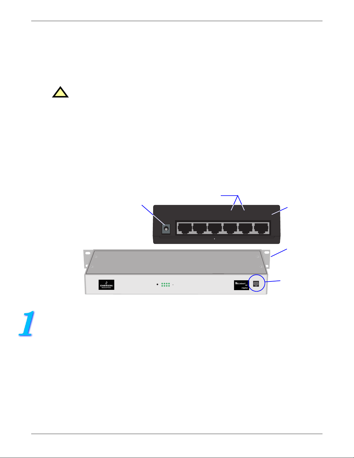
Serial Ports - Connect either
DCN Power Port
Liebert OpenComms EM
(EM PDU Controller)
to Power Strip EIA-232 Port
Sensor 2 Sensor
Modem DCN Ethernet
1
Serial 2 Serial
1
Ethernet
Port
Mounting
Bracket on
Liebert MP
Advanced
Power Strip
(MP-C5120)
1234568
POWER
8
EIA-232
either side
EIA-232 Port
CONFIGURATION WITH OPENCOMMS EM
1. Connect power to the DCN port on the OpenComms EM and to your MP Advanced Power Strip.
2. Connect the six-wire end of the serial cable provided with the OpenComms EM to the EIA-232 port of
your MP Advanced Power Strip.
3. Connect the other end (eight-wire) of the serial cable to either Serial 1 or Serial 2 of the
OpenComms EM.
4. Connect a straight-through CAT5 Ethernet cable from your network to the Ethernet port on the back
of the OpenComms EM.
2
Page 3

ASSIGN AN IP ADDRESS
NOTE
These steps must be done on the same network segment where the OpenComms EM is connected.
If your network uses static IP addresses and your computer has a Windows operating system, follow the
steps below. Otherwise, consult the OpenComms EM user manual (SL-28210).
1. Obtain an IP address for the OpenComms EM from your network administrator.
2. Insert the OpenComms EM CD in your computer’s CD drive.
3. Click on the Start button, then on Run, then Browse to the file IPSET.exe on the CD and click
Open.
4. Click OK to open the IPSet window (at right).
5. In the Target area:
a. Enter the OpenComms EM IP address
b. Enter your network’s Subnet Mask
c. Enter your router’s IP address in the Default
box.
d. Enter the MAC address found on the bottom
of your OpenComms EM.
6. Apply the changes. If the device identification is
successful, the message “Successfully set IP
address” appears in the Status box. (If not, the
message “No response from target” appears in
the Status box.)
7. Click on the Close button.
Enter a
unique
IP address
Subnet
mask
Default
gateway
address
Enter the unit’s
MAC address
(look on
bottom of unit)
Apply button
OPEN THE WEB INTERFACE AND LOG IN
• Open an Internet browser and enter the unit’s IP address or hostname into the browser’s address bar
and press the Enter key. The Login window appears.
Address
bar
Login
window
User Name
default = “liebert”
Password
default = no password
• Enter the default user name—liebert— in the User Name box (case-sensitive).
• Leave the Password box blank (the default liebert user account has no password).
•Click OK. If the login is successful, a message appears. Click OK.
When ready to exit the user interface, click on the Summary tab at the top of the Web interface, then
click on the Log Out button in the left side of the window.
3
Page 4

CONFIGURATION WITH LIEBERT MP ADVANCED ACCESS SERVER
HYPERTERMINAL SETTINGS
Liebert MP Advanced
Power Strip
(MP-C5120)
Mounting
Bracket on
either side
1234568
POWER
8
EIA-232
EIA-232 Port
EIA-232 Port - Connect
to Power Strip EIA-232 Port
Liebert MP Advanced
Access Server
Ethernet Port
MP-DS74 Card With
Configurable
Communication Ports
(MP-S5138)
I/0 MODULE
NETWORK
INTERFACE
EIA-232
ETHERNET
ROUTE LINE
CX3
EIA-232
DS62
CX4
3
4
CX1
DS74
CX2
1
2
MADE IN USA
100-240VAC
??????????
0.21-0.12AMPS
On/Off Switch
(not on all
models)
MAKE CONNECTIONS
1. Connect power to the Liebert MP Advanced Access Server and turn the unit On (the On/Off switch is
on the rear of the unit; some units do not have this switch; they are energized whenever their power
cord is plugged into a power source).
2. Attach the adapter (RS-232 to RJ-45) to one end of a silver configuration cable (included) and connect
that end of the cable to a COM port on a computer. Connect the other end of the cable to the EIA-232
port of the MP-DS62 card on your MP Advanced Access Server.
3. Plug one end of the second silver RJ-45 cable into any of the ports in the MP-DS74 module in your
Liebert MP Advanced Access Server; plug the other end of the cable into the EIA-232 port on your MP
Advanced Power Strip.
ESTABLISH COMMUNICATION WITH CARD
1. Use terminal emulation software, such as HyperTerminal™, to open a
direct connection to the MP-DS62 card. Use the settings at right. Press
Enter for the Main Menu, choose “C” and then “1” to configure the
MP-DS62 port.
2. Enter “8” for Network Port Configuration (below left), then “7,” then “N”
to disable DHCP (below right).
Choose “8” to change
Network Port
Configuration
Enter “7”
to change
DHCP setting
Baud Rate: 9600
Data Bits: 8
Parity: None
Stop Bits: 1
Flow Control: N/A
Enter “N”
to disable
DHCP
4
Page 5

SET THE IP ADDRESS
1. Select “1” to set the IP Address for Module 1. Enter an IP address (below). The address must be
unique on your system (obtain this from your network administrator).
2. Press Enter to return to the Network Port Configuration menu.
Enter IP address
3. Choose “2” to set the Subnet Mask for your system (obtain this from your network administrator).
SET THE GATEWAY ADDRESS
1. Return to the Network Port Configuration menu and choose “3” to set the Gateway Address (the IP
address of your network router). Follow the prompts to exit HyperTerminal and save your changes.
2. Verify that your settings are correct and were saved by using a command prompt to ping the
MP-C/MP-S unit: Start>Run>CMD.
3. At the command prompt enter:
ping [IP address]
4. Press “Enter.”
5
Page 6

Liebert Corporation
1050 Dearborn Drive
P.O. Box 29186
Columbus, OH 43229
Telephone: 1-800-877-9222
Facsimile: 1-614-841-6022
www.liebert.com
© 2006 Liebert Corporation
All rights reserved throughout the world. Specifications subject
to change without notice.
® Liebert and the Liebert logo are registered trademarks of
Liebert Corporation. All names referred to are trademarks or
registered trademarks of their respective owners.
SL-20812 (01/06) Rev. 2
6
 Loading...