

Page 1
LIEBERT NX 1+1 SYSTEM
PRODUCT SPECIFICATION AND INSTALLATION SHEET
+
General
The Liebert NX UPS uses intelligent and reliable
decentralized technology to achieve parallel operation of two modules of the same rating.
The 1+1 system is used to:
• Increase the reliability of the system to ensure
adequate power supply to the critical load connected.
• Increase serviceability and allow the execution of
maintenance operations and reparations without
affecting the ordinary operating conditions of the
system (depending on the redundancy level).
CAUTION
!
An external maintenance cabinet is strongly
recommended to maintain the power supply to
load in case of complete maintenance.
Conditions for Parallel System
1. Each UPS module should have the same rating,
the same firmware and hardware version.
2. Each UPS module must have the same bypass
source.
3. The outputs of all UPS modules are connected
altogether.
4. The main inputs can be from different sources, but
the phase rotation sequence of main inputs,
bypass inputs and outputs must be correct and the
same.
5. The parallel logic cable and load sharing cable
must be connected in a ring correctly (See
Figure 2)
Features of Parallel System
1. The hardware and firmware for parallel UPS
module operation is standard in the Liebert NX,
and the configuration can be set up by changing
the settings in configuration software.
2. It is easy to install the parallel cables in a ring,
providing high reliability and redundancy. And
the intelligent paralleling logic provides the user
with maximum flexibility. For example, shutting
down or starting up the UPS modules in the
parallel system can be done in any sequence. If an
overload transfer occurs, the whole system can
recover automatically from bypass mode after the
overload is cleared.
3. The total load of the parallel system can be
queried from each module’s liquid crystal display
screen.
4. Optional monitoring background software can
treat the entire parallel system as a big
single-module UPS, and provide corresponding
management. It can also get the information for all
modules by connecting to just one of the modules.
1
Page 2
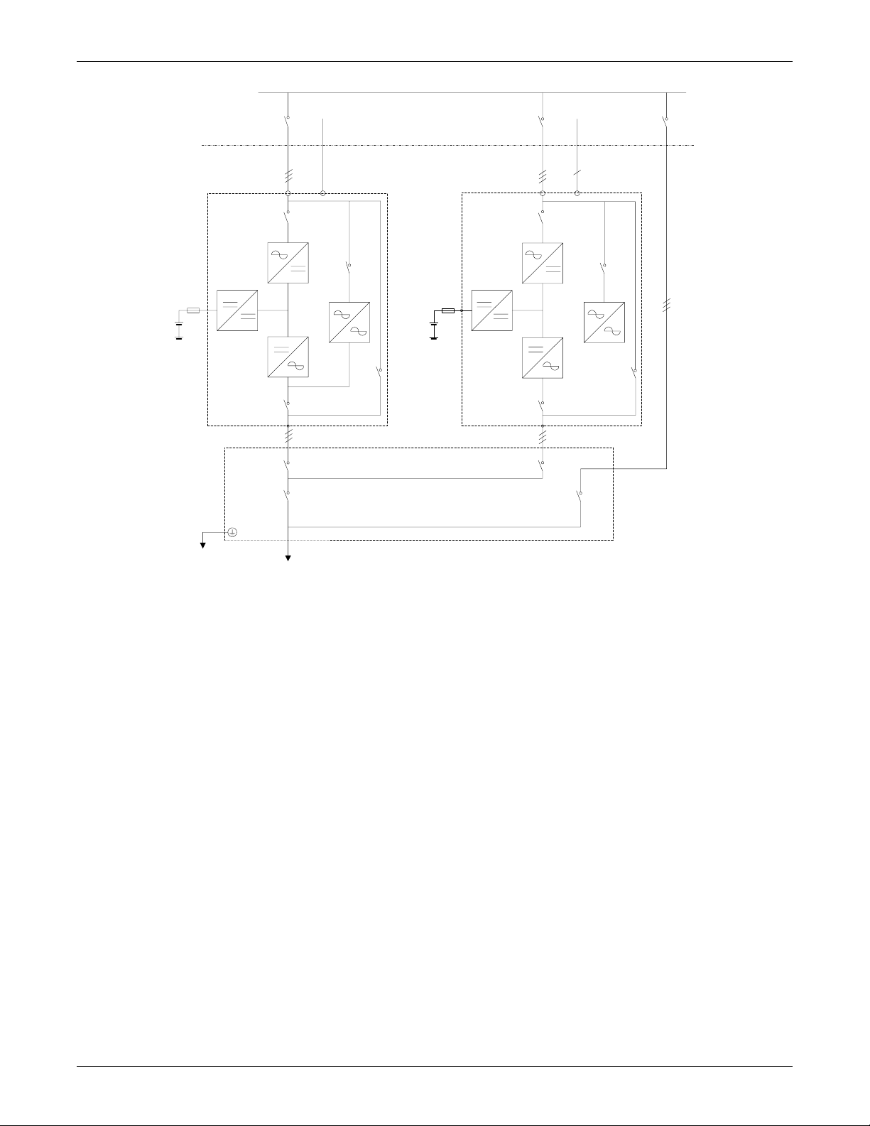
Figure 1 '1+1' System block diagram
Supplied by Others
Input Utility
Supply A B C
UPS1 UPS2
Charger Charger
Inverter Inverter
NN
CB1 CB1
SW1-C SW1-C
Static
Switch
Battery 2Battery 1
SW1-D SW1-D
SW1-A SW1-A
Q1EXT Q2EXT
Distribution Panel
Input Utility
Supply A B C
FuseFuse
RectifierRectifier
Static
Switch
A B CA B C
QBYPQUPS
To L o ad
Operating Principles
Redundancy Paralleling
The redundancy parallel system can noticeably
improve system reliability. In normal condition, neither UPS module works at full load. That means
that even if the load is increased, the system will not
transfer to bypass. And when a UPS module shuts
down due to any failure, the remaining UPS module
can still power and protect the load. When redundancy is lost due to module failure or load increase,
the parallel system will trigger an alarm.
Operation Modes Summary
The parallel system also has operation modes such
as normal, battery, bypass and maintenance bypass.
All UPS modules in the 1+1 parallel system operate
in coordination.
• Normal Mode Operation
The load is powered by the inverters of all the
UPS modules in the system. If the frequency of
bypass is within the synchronous range, the
inverter will be synchronized with the bypass.
Otherwise, the system will operate at nominal
frequency.
• Battery Mode Operation
The batteries of all UPS modules power the load
through their inverters. The system operates at
nominal frequency.
• Bypass Mode Operation
The condition to transfer to bypass mode is the
same as that for a single module system. The
bypass of all the UPS modules powers the load.
• Maintenance Bypass Mode Operation
The sequence to transfer to maintenance bypass
mode is the same as for transferring a singlemodule system. The maintenance bypass
switches should be switched on as synchronously
as possible. Thus the system can be repaired
without interrupting the power supply to critical
load.
Intermodule Control
Two kinds of signals are used for the parallel cables:
• Analog signals—UPS output unbalanced current
• Digital signals—control logic signals, parallel
cable status
Parallel control cables should be connected to the
parallel board (M3) of all modules and form a ring to
provide redundancy as shown in Figure 2.
Two types of Parallel control cables needed:
• DB9 for analog signals with one end DB9/F and
one end DB9/M
• DB25 for digital signals with one end DB25/F and
one end DB25/M
These come in lengths of 5m, 10m, &15m.
2
Page 3

Installation
The basic installation procedure of parallel system is
the same as that of single module system. The following sections only introduce the installation procedures specific to the parallel system.
Cabinet Installation
Parallel system composed of two UPS modules
The two UPS modules that will form the 1+1 system
should be placed side-by-side. Each battery cabinet
is placed next to its corresponding UPS module.
Preliminary Checks
Each UPS module should have the same rating, the
same firmware and the same hardware version.
Refer to the instructions in Conditions for Paral-
lel System on page 1.
Figure 2 Connecting 1+1 system parallel control
cables
1 2
#1 UPS Module #2 UPS Module
Parallel Board Parallel Board
X5
X4
3
X1-1 X1-1X1-2 X1-2
X4
X2-2X2-1X2-2X2-1
Protective Devices
Refer to the instructions supplied in the Liebert NX
installation manual, SL-25215.
Power cables
Wiring of power cables is similar to that of single
module system (see the Liebert NX installation manual, SL-25215). The bypass sources of all modules
should be the same, and the outputs should be connected altogether correctly.
NOTE
The length and specifications of power
cables including the bypass input cables
and UPS output cables should be the same,
thus the load can be shared evenly in
bypass mode.
Parallel Control Cables
Make the connections described below on the parallel logic board (M3) inside the Liebert NX:
• Connect one end of the DB-25 interconnecting
cable to the X2_1 connector of UPS 1 and the other
end to the X2_2 connector of UPS 2.
• Connect one end of the DB-25 interconnecting
cable the X2_2 connector of UPS 1 and the other
end to the X2_1 connector of UPS 2.
• Connect one end of the DB-9 interconnecting cable
the X1_1 connector of UPS 1 and the other end to
the X1_2 connector of UPS 2.
• Connect one end of the DB-9 interconnecting cable
the X1_2 connector of UPS 1 and the other end to
the X1_1 connector of UPS 2.
The connections are shown above in Figure 2.
4
1 2
UPS Unit
Parallel Connection Board
3
4
Interconnecting Cables
Commissioning a Parallel System
CAUTION
!
The operations in this section must be
performed by authorized electricians or
qualified technical personnel. If you have
any difficulties, contact Liebert Global
Services at 800-543-2378.
Check the input and output wiring of each UPS module. Ensure that the phase rotation sequence of the
main inputs and the bypass inputs and outputs of
each UPS module are the same. Ensure the parallel
cables are connected firmly.
It is assumed that the installation is complete, the
system has been commissioned by authorized personnel and the external power isolators are closed.
Before startup, disconnect the load.
Start the UPS modules separately and set the
parameters of each UPS module through configuration software. Pay particular attention to the parameters directly relevant to the parallel system:
• UPS Configuration: Each UPS module belonging
to the parallel system should be set as Parallel
configuration.
• UPS ID No.: Each UPS module should have a
unique identification number in the parallel system.
• Parallel system requisite UPS units: Set the minimum number of UPS modules to support the
user’s expected load. For 1+1 systems this settings
needs to be set to 1.
• Parallel system redundant UPS units: Set the
redundant number of UPS modules which will not
cause the parallel system transfer to bypass even
3
Page 4

if they get failure during operation. For 1+1 systems, this settings needs to be set to 1.
NOTE
The settings should be the same for all
modules within the parallel system, except
the UPS ID No.
System Startup
1. Start each UPS normally as described in Liebert
NX installation manual. SL-25215.
2. Turn on the inverter of each UPS module one at a
time.
3. Apply the load after the last UPS module transfers
to inverter. The total load can be determined
through the LCD of either UPS.
4. Verify the load rate of each UPS module. If the
load rates are roughly the same, then the parallel
system may be assumed to be operating normally.
Figure 3 Connecting EPO push button
NOTE
If one module cannot transfer to inverter
mode long after its inverter is on, its output
connection may not be good or its output
phase rotation may not be coincident with
other modules. At this time, the LCD for the
UPS module will display “inverter
asynchronous” and the inverter indicator
will flash continuously. If either UPS
module makes abnormal noise after it
transfers to inverter, its parallel cables may
be incorrectly connected.
Emergency Power Off (EPO)
The external emergency stop facility is identical to
that described for the single unit installation — that
an individual emergency stop button is provided for
each unit. Note that this is a Normally Open switch.
UPS2
X2
EPO-H
X2
EPO-H
EPO- L
EPO-L
Monitor board
Monitor board
EPO
Liebert Corporation
1050 Dearborn Drive
P.O. Box 29186
Columbus, OH 43229
© 2004 Liebert Corporation
All rights reserved throughout the world. Specifications subject to change without notice.
UPS1
Telephone: 1-800-877-9222
Facsimile: 1-614-841-6022
www.liebert.com
® Liebert and the Liebert logo are registered trademarks of
Liebert Corporation. All names referred to are trademarks or
registered trademarks of their respective owners.
SL-25246 (10/04) Rev. 0
4
 Loading...