

Page 1

POWER PROTECTION
Extended Battery Cabinet for Nfinity
USER MANUAL
Page 2

Page 3

i
TABLE OF CONTENTS
IMPORTANT SAFETY INSTRUCTIONS . . . . . . . . . . . . . . . . . . . . . . . . . . . . . . . . . . . 1
ELECTROMAGNETIC COMPATIBILITY . . . . . . . . . . . . . . . . . . . . . . . . . . . . . . . . . . . . . . . 1
OPERATING ENVIRONMENT . . . . . . . . . . . . . . . . . . . . . . . . . . . . . . . . . . . . . . . . . . . . . 1
GLOSSARY OF SYMBOLS . . . . . . . . . . . . . . . . . . . . . . . . . . . . . . . . . . . . . . . . . . . . . 2
GENERAL DESCRIPTION . . . . . . . . . . . . . . . . . . . . . . . . . . . . . . . . . . . . . . . . . . . . . . 3
SYSTEM DESCRIPTION . . . . . . . . . . . . . . . . . . . . . . . . . . . . . . . . . . . . . . . . . . . . . . . . 3
FEATURES:. . . . . . . . . . . . . . . . . . . . . . . . . . . . . . . . . . . . . . . . . . . . . . . . . . . . . . . . . 3
PREPARATION. . . . . . . . . . . . . . . . . . . . . . . . . . . . . . . . . . . . . . . . . . . . . . . . . . . . . . . 4
INSPECTION . . . . . . . . . . . . . . . . . . . . . . . . . . . . . . . . . . . . . . . . . . . . . . . . . . . . . . . . 4
ENVIRONMENT . . . . . . . . . . . . . . . . . . . . . . . . . . . . . . . . . . . . . . . . . . . . . . . . . . . . . . 4
REQUIRED SETUP EQUIPMENT . . . . . . . . . . . . . . . . . . . . . . . . . . . . . . . . . . . . . . . . . . 4
SITE PREPARATION. . . . . . . . . . . . . . . . . . . . . . . . . . . . . . . . . . . . . . . . . . . . . . . . . . . 4
UNLOADING . . . . . . . . . . . . . . . . . . . . . . . . . . . . . . . . . . . . . . . . . . . . . . . . . . . . . . . . . 5
UNLOADING THE EXTENDED BATTERY CABINET . . . . . . . . . . . . . . . . . . . . . . . . . . . . . . 5
STATIONARY MOUNTING . . . . . . . . . . . . . . . . . . . . . . . . . . . . . . . . . . . . . . . . . . . . . . . 6
OPTIONAL STATIONARY MOUNTING . . . . . . . . . . . . . . . . . . . . . . . . . . . . . . . . . . . . . . . 6
INSTALLATION. . . . . . . . . . . . . . . . . . . . . . . . . . . . . . . . . . . . . . . . . . . . . . . . . . . . . . . 7
GROUNDING . . . . . . . . . . . . . . . . . . . . . . . . . . . . . . . . . . . . . . . . . . . . . . . . . . . . . . . . 7
COMMUNICATIONS . . . . . . . . . . . . . . . . . . . . . . . . . . . . . . . . . . . . . . . . . . . . . . . . . . . 7
DC POWER . . . . . . . . . . . . . . . . . . . . . . . . . . . . . . . . . . . . . . . . . . . . . . . . . . . . . . . . 7
CONFIGURATION SETTING. . . . . . . . . . . . . . . . . . . . . . . . . . . . . . . . . . . . . . . . . . . . . . 8
MODULE REPLACEMENT . . . . . . . . . . . . . . . . . . . . . . . . . . . . . . . . . . . . . . . . . . . . . . 9
R
EMOVING MODULES . . . . . . . . . . . . . . . . . . . . . . . . . . . . . . . . . . . . . . . . . . . . . . . . . 9
REPLACING MODULES. . . . . . . . . . . . . . . . . . . . . . . . . . . . . . . . . . . . . . . . . . . . . . . . 10
BATTERY RUN TIMES . . . . . . . . . . . . . . . . . . . . . . . . . . . . . . . . . . . . . . . . . . . . . . . . 11
I
NTERNAL AND EXTENDED BATTERY CABINETS (MINUTES) . . . . . . . . . . . . . . . . . . . . . 11
Page 4

Page 5

1
IMPORTANT SAFETY INSTRUCTIONS
SAVE THESE INSTRUCTIONS
This manual contains important instructions that
should be closely followed during installation of
this Extended Battery Cabinet.
This product is designed for commercial/industrial
use only. This product is not intended for use with
life-support and other designated “critical” devices.
Observe the following precautions when working
with batteries:
This UPS equipment is designed for use on a
properly grounded electrical system. This
equipment is intended to be installed by a
qualified, certified electrician who must review and
approve customer-supplied wiring, circuit breakers
and earth connections to ensure compliance with
technical standards and local electrical codes.
Installation instructions and warning notices only
for use by qualified personnel are located in the
INSTALLATION section of this manual.
Electromagnetic Compatibility
This UPS equipment complies with the
requirements of the EMC directive 89/336/EEC,
the published technical standards and Class A
digital device pursuant to Part 15 of FCC rules.
These limits provide reasonable protection against
harmful electromagnetic interference in a
commercial environment.
This device generates, uses and radiates radio
frequency energy and, if not installed and used in
accordance with the instruction manual, may
cause harmful interference with radio
communications. Operating this device in a
residential area is likely to cause harmful
electromagnetic interference that the user must
correct at his own expense.
Operating Environment
Operate the Extended Battery Cabinet in an indoor
environment only in an ambient temperature range
of 32°F to 104°F (0°C to 40°C). For optimum
battery life, operate the unit in an ambient
temperature range of 59°F to 77°F (15°C to 25°C).
Install the Extended Battery Cabinet in a clean
environment, free from conductive contaminants,
moisture, flammable liquids, gases and corrosive
equipment in an indoor environment.
Turn the UPS off and isolate the system before
cleaning. Use only a soft cloth, never liquid or
aerosol cleaners. Keep the front and rear vents
free of dust accumulation that could restrict air
flow.
Never block or insert any object into the ventilation
holes or other openings.
This Extended Battery Cabinet contains user
replaceable modules. No attempts should be
made to access the interior of any module. See
MODULE REPLACEMENT on page 9 for details
on this procedure.
!
WARNING
Lethal voltages may be present
within this unit even when it is
apparently not operating. Observe
all cautions and warnings in this
manual. Failure to do so may
result in serious injury or death.
Never work alone.
!
CAUTION
DO NOT dispose of battery
modules in a fire; the battery
module may explode.
DO NOT open or mutilate
batteries; released electrolyte is
harmful to skin and eyes and may
be toxic.
A battery can present a risk of
electrical shock and high shortcircuit current. The following
precautions should be observed
when working on batteries.
• Remove watches, rings and other
metal objects.
• Use tools with insulated handles.
!
CAUTION
Lead-acid batteries contain
hazardous toxic materials. Handle,
transport and recycle in
accordance with local regulations.
Page 6

2
GLOSSARY OF SYMBOLS
Risk of electrical shock
Indicates caution followed by important instructions
AC input
AC output
Requests the user to consult the manual
Indicates the unit contains a valve-regulated lead acid
battery
Recycle
DC voltage
Equipment grounding conductor
Bonded to ground
AC voltage
OFF
ON
Standby
No telecommunication connection
Locked position
Unlocked position
Contact closure signals
Serial communications
i
Page 7

3
GENERAL DESCRIPTION
System Description
The Extended Battery Cabinet is a modular
cabinet intended for use with the Nfinity™ modular
UPS system. The cabinet will hold a maximum of
12 battery modules with the same level of
monitoring and control as the battery modules
fitted in the UPS.
Features:
• Up to four Extended Battery Cabinets can be
used with a single Nfinity UPS
• Up to 12 battery modules per cabinet
• A user-friendly interface, on the UPS, for custom configuration
• Continuous system monitoring
• Warning alarms and event logs.
FRONT VIEW
REAR VIEW
Page 8
4
PREPARATION
These installation instructions provide all the
information needed for positioning the Extended
Battery Cabinet (including environmental
requirements) and for connecting the input and
output power cables.
Inspection
Upon receiving the Extended Battery Cabinet,
examine the packaging for any signs of
mishandling or damage. If any damage is noted,
call your local Liebert representative and/or notify
your carrier.
Environment
Required Setup Equipment
The tools below are required in order to properly
set up your Extended Battery Cabinet.
• Pallet jack
• 13 mm or 1/2" wrench
• Flathead screwdriver
• #2 Phillips screwdriver
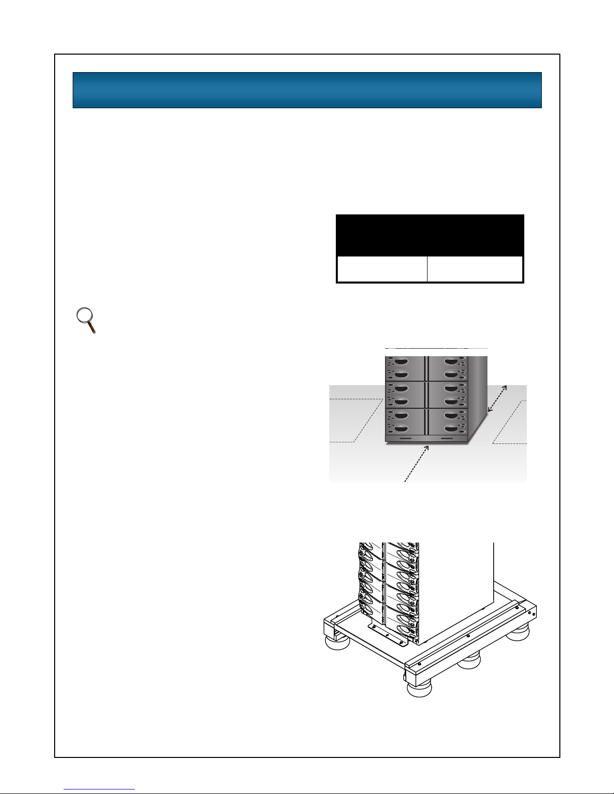
Site Preparation
When deciding where to locate your Extended
Battery Cabinet, consider the weight and size of
the unit. Make sure that the structural integrity of
the floor can withstand the weight. Refer to the
table below for size and fully populated weight
considerations:
Check to make sure that your Extended Battery
Cabinet will be located in a well-ventilated area
with at least 300 mm (12”) behind it. It should have
at least one meter (39 in.) in front to change
modules when necessary.
The unit frame is bolted to the shipping pallet to
ensure safety. It is recommended that a pallet jack
be used to transport the unit to its operating
location (prior to unbolting the unit).
NOTE
Operating in temperatures above 77°F
(25°C) will reduce battery life. The
environment must be free of conductive
contaminants and excessive moisture
(water condensation), flammable vapors,
chemical fumes, or corrosive gases and
liquids.
Max Weight
lbs (kg)
H x W x D
in (mm)
942
(427)
52" x 20" x 28"
(1320 x 508 x 711)
1 meter
(39 in.)
300 mm
(12 in)
Page 9

5
UNLOADING
Unloading the Extended Battery
Cabinet
1. Once the Extended Battery Cabinet is near the
desired operating location, remove the cardboard cover.
2. Use a 13 mm (1/2") wrench to remove the four
mounting bolts from each of the pallet brackets. Remove mounting brackets from the pallet
and cabinet. Keep brackets and bolts for future
transportation of cabinet or for additional stability once in place.
3. Remove the metal ramp from the bottom of the
battery cabinet, rotating it. Fit ramp in pallet
slot as shown above.
4. Using two people, slowly move the cabinet
down the ramp until the Extended Battery
Cabinet is on a level surface.
!
CAUTION
This battery cabinet is heavy (see
weight on previous page). At least
two people should be present to
unload it from the pallet.
Page 10

6
5. Once the Extended Battery Cabinet is in the
desired location, adjust the leveling feet to
secure its position.
Stationary Mounting
Additional stability can be added by bolting the
mounting brackets (used in shipping) to the floor.
Optional Stationary Mounting
For greater stability, use a higher-grade bolt. Refer
to the dimensions below when drilling holes for
stationary mounting.
1/2"
(13 mm)
4.75”
(120 mm)
center line
28”
(711 mm)
4.75”
(120 mm)
5/16" diameter
(7.94 mm)
6 places
Page 11

7
INSTALLATION
Grounding
The Extended Battery Cabinet must be installed
with a dedicated grounding electrode conductor
(GEC) to the site grounding system in accordance
with national and local wiring codes and regulations
as shown below.
Communications
To enable communication between the Extended
Battery Cabinet and the Nfinity, it is necessary to
install an Intellislot Battery Card (IBC) in the
Intellislot port of the UPS. See below. A second,
included IBC is installed in the Extended Battery
Cabinet. The provided serial cable is to be
connected between the two cards.
DC Power
DC connection with the UPS unit must be via the
factory-supplied battery cables, or if longer
connection cable is required, via the optional
Extended Battery Cable kits. See below.
After connections are made and verified, the
output circuit breaker must be closed to connect
the batteries inside the Extended Battery Cabinet
to the Nfinity UPS. To do this, move the handle of
the circuit breaker under the lower-most bezel to
the ON position (see illustration below for circuit
breaker location).
L1 L2
GEC
Connection
Communications
NOTE
Failure to turn on the circuit breaker
may cause damage to the batteries in the
Extended Battery Cabinet. Failure to
follow this procedure may limit your
warranty.
DC Power
Output Circuit Breaker
Page 12

8
Configuration Setting
For the UPS system to be aware of the presence
of the Extended Battery Cabinet(s), the system
has to be configured with the necessary
information. To enter the information, follow the
steps below:
After initialization, pressing the button will
take you to the main menu.
Scroll down to UPS Configuration, and select
it by pressing the button.
Scroll down to Change Settings; press
Scroll down to Intellislot Battery Ca.; select it
by pressing
Enter the quantity of Extended Battery Cabinets installed.
Press
return arrow and then press to
save your changes and exit.
The system is now configured.
Main Menu
UPS Status
> UPS Configuration
Display Date/Time
Event Log
Alarm Log
Transfer to Bypass
Module Replacement
Tools
UPS Configuration
UPS Configuration
Review Settings
> Change Settings
Service Mode
Change Settings
Input Voltage
Frequency Sync Range
Frequency Slew Rate
Set Password
Auto Battery Test
Low Battery Warning
Auto Restart
User Settings
Set Date/Time
Max Load Alarm Set
UPS Shutdown Delay
Redund Alarm Set
Service Contact
Remote Shutdown
External Battery
Bypass Alarm Mode
> Intelli-Batt Ca.
Air Filter Reminder
Factory Defaults
ESC
Page 13

9
MODULE REPLACEMENT
Follow the instructions below when replacing a
battery module and when adding modules to the
system.
Removing Modules
1. Remove bezel cover of appropriate module.
When replacing a battery module, verify the
faulty module by confirming the amber LED is
lit.
2. Turn fastener counterclockwise until it is
loosened.
3. Start to pull out module. About 2/3 out it will
stop. Slide module away from the center of the
unit.
4. Dispose of the removed module in an
environmentally responsible way that complies
with local codes and regulations or return the
module to Liebert for proper disposal.
!
CAUTION
Battery modules are heavy: 30 kg
(66 lbs). Make sure to use two
people when removing a battery
module. Continue to pull until
module is removed (seen at
right).
NOTE
Battery modules may contain shipping
screws. These screws may be removed
and discarded.
Status LED
Fault LED
WARNING
POTENTIAL TIP HAZARD
Install all modules starting with bottom
bays and moving to top. For module
removal, start with top bays and proceed
to bottom. Do not remove more than one
module at a time—doing so may cause
unit to tip over and cause serious injury.
Page 14

10
Replacing Modules
1. Lift the module to the appropriate bay, resting
the end of the module on the bay shelf. Use
caution not to rest the module on the lower
bezel cover.
2. Push the module into bay. Once it is half way
in, slide the module sideways toward the
center of the unit. Continue pushing module
until fully inserted.
3. Press and turn fastener clockwise until locked.
4. Wait about 15 seconds as the module
performs a start-up test and synchronizes with
the other modules. Both the amber and green
LEDs should be flashing. A green flashing
LED will then confirm that the module is
properly connected.
5. Replace the bezels.
Page 15

11
BATTERY RUN TIMES
Internal and Extended Battery Cabinets (minutes)
Load VA Load Watts
Quantity of
Battery Modules
Quantity of
Extended Battery Cabinets
123456789101 2 3 4
20,000 14,000 - - - - 7 9 - - - - 25 51 75 99
19,500 13,650 - - - - 7 9 - - - - 25 56 80 104
19,000 13,300 - - - - 7 9 - - - - 26 57 81 105
18,500 12,950 - - - - 8 11 - - - - 27 58 82 106
18,000 12,600 - - - - 8 12 - - - - 28 61 97 133
17,500 12,250 - - - - 8 12 - - - - 28 63 99 135
17,000 11,900 - - - - 8 12 - - - - 29 64 100 136
16,500 11,550 - - - - 9 13 - - - - 30 66 102 138
16,000 11,200 - - - 7 8 12 17 - - - 32 68 104 140
15,500 10,850 - - - 7 9 13 17 - - - 33 70 106 142
15,000 10,500 - - - 7 11 14 18 - - - 34 72 108 144
14,500 10,150 - - - 8 12 15 19 - - - 36 74 110 146
14,000 9,800 - - - 8 13 16 20 - - - 37 82 130 178
13,500 9,450 - - - 8 13 16 20 - - - 38 85 133 181
13,000 9,100 - - - 9 13 17 21 - - - 39 86 134 182
12,500 8,750 - - - 10 14 18 22 - - - 42 90 138 186
12,000 8,400 - - 7 12 16 20 24 28 - - 44 93 141 189
11,500 8,050 - - 7 12 17 21 25 29 - - 46 97 145 193
11,000 7,700 - - 7 12 17 21 26 30 - - 48 101 149 197
10,500 7,350 - - 8 14 18 23 28 32 - - 51 111 171 231
10,000 7,000 - - 9 15 19 24 29 34 - - 54 113 173 233
9,500 6,650 - - 10 15 21 26 30 36 - - 57 119 179 239
9,000 6,300 - - 11 16 22 28 33 38 - - 60 131 203 275
8,500 5,950 - - 12 17 23 29 35 40 - - 64 139 211 283
8,000 5,600 - 7 13 19 25 31 37 43 49 - 68 142 214 286
7,500 5,250 - 8 14 21 28 34 40 47 53 - 73 149 221 293
7,000 4,900 - 8 16 23 30 36 43 50 57 - 78 161 245 329
6,500 4,550 - 9 17 24 32 40 47 55 62 - 84 174 258 342
6,000 4,200 - 11 19 24 36 43 51 60 68 - 92 190 286 382
5,500 3,850 - 12 21 23 39 47 56 66 74 - 101 203 299 395
5,000 3,500 - 14 23 28 42 52 61 72 80 - 110 223 331 439
4,500 3,150 - 15 25 37 47 57 67 78 88 - 119 245 365 485
4,000 2,800 7 19 31 43 55 66 79 91 104 115 140 285 429 573
3,500 2,450 9 23 37 51 65 79 93 107 123 136 165 333 489 645
3,000 2,100 11 28 44 60 76 93 109 126 143 159 192 387 567 747
2,500 1,750 14 33 52 71 89 109 128 147 167 185 224 448 652 856
2,000 1,400 18 42 65 88 112 136 160 183 207 230 276 554 818 1,082
1,500 1,050 26 57 87 119 151 182 213 243 276 306 367 734 1,094 1,454
1,000 700 45 94 144 195 246 294 344 393 444 493 570 1145 1,685 2,225
900 630 50 105 160 216 273 327 382 436 492 547 627 1261 1,849 2,437
800 560 55 116 177 238 300 359 420 480 540 601 684 1378 2,014 2,650
700 490 61 128 195 263 331 396 463 529 594 661 752 1515 2,223 2,931
600 420 72 149 227 304 382 457 535 610 685 762 887 1776 2,628 3,480
500 350 82 171 258 346 433 518 606 691 777 862 1022 2036 3,032 4,028
NOTE: Backup times are in minutes and are based on resistive loading at an ambient temperature of 77°F (25°C).
Extended battery cabinets are fully loaded with 12 battery modules.
Extended battery cabinets assume that the UPS frame is fitted with all available battery modules.
Page 16

12
Page 17

Page 18

The Company Behind the Products
With over a million installations around the globe,
Liebert is the world leader in computer protection
systems. Since its founding in 1965, Liebert has
developed a complete range of support and
protection systems for sensitive electronics:
• Environmental systems—close-control air
conditioning from 1 to 60 tons
• Power conditioning and UPS with power
ranges from 300 VA to more than 1000 kVA
• Integrated systems that provide both
environmental and power protection in a
single, flexible package
• Monitoring and control—from systems of any
size or location, on-site or remote
• Service and support through more than 100
service centers around the world and a 24/7
Customer Response Center
While every precaution has been taken to ensure
the accuracy and completeness of this literature,
Liebert Corporation assumes no responsibility and
disclaims all liability for damages resulting from
use of this information or for any errors or
omissions.
© 2002 Liebert Corporation
All rights reserved throughout the world.
Specifications subject to change without notice.
® Liebert and the Liebert logo are registered
trademarks of Liebert Corporation. All names
referred to are trademarks or registered
trademarks of their respective owners.
SL-23966 (3/02) Rev. 2
Technical Support
United States
1050 Dearborn Drive
P.O. Box 29186
Columbus, OH 43229
Single-Phase UPS
800-543-2378
Outside the United States
614-841-6598
3-Phase UPS
800-543-2378
Environmental Control
800-543-2778
Italy
Via Leonardo Da Vinci 8
Zona Industriale Tognana
35028 Piove Di Sacco (PD)
+39 049 9719 111
FAX: +39 049 5841 257
Asia
23F, Allied Kajima Bldg.
138 Gloucester Road
Wanchai
Hong Kong
+852 2 572 2201
FAX: +852 2 831 0114
Web Site
www.liebert.com
POWER PROTECTION
Extended Battery Cabinet for Nfinity
USER MANUAL
 Loading...