

Liebert LM Series, LM1 Series, LM2 Series Installation, Operation And Maintenance Manual

Surge
®
Suppression
Systems
LIEBERT LM SERIES SURGE PROTECTIVE DEVICE
INSTALLATION, OPERATION AND MAINTENANCE MANUAL
TABLE OF CONTENTS
UNPACKING AND INSTALLATION....................................................................................... 2
Unpacking and Preliminary Inspection............................................................................. 2
Handling Considerations .................................................................................................... 2
Storage.................................................................................................................................. 2
Location Considerations..................................................................................................... 2
Door Closing Adjustments.................................................................................................. 2
ELECTRICAL CONNECTIONS .............................................................................................. 5
Voltage Rating & Source Configurations......................................................................... 5
Parallel Connection............................................................................................................. 5
System Grounding & Bonding........................................................................................... 9
OPERATION.............................................................................................................................. 10
TROUBLESHOOTING / REPAIR / MAINTENANCE........................................................... 12
Red LED on Door Illuminated & Green LED on Door Extinguished........................... 12
Display Blank – No Red or Green LEDs Illuminated on Door...................................... 12
Replacing Power Supply Board (Units with Counter or Audible Alarm Options)...... 13
Preventative Maintenance (Inspection and Cleaning)................................................... 13
LIMITED WARRANTY.............................................................................................................. 14
DECLARATION OF CONFORMITY....................................................................................... 16
FIGURE
Figure 1. Cabinet Data, Form C Contact and Wiring.................................................... 3
Figure 2. Voltage Ratings and Power Source Configurations..................................... 6
Figure 3. Typical Parallel Connections (without External Disconnect Switch) ......... 8
Figure 4. Typical Parallel Connections (with External Disconnect Switch)............... 8
Figure 5. Remote Monitor Panel...................................................................................... 11
Installation, Operation - 1 - LM Series
and Maintenance Manual Rev 0, 5/99

INSTALLATION,
O
PERATION AND
MAINTENANCE
MANUAL
TRANSIENT VOLTAGE SURGE SUPPRESSION
LM Series
Liebert

TRANSIENT VOLTAGE SURGE SUPPRESSION
A World Leader in
Computer Support
Systems
Environment Control
Power Protection
Site Monitoring /
Control
Liebert Cor poration
designs, manufactures
and markets complete
systems for improvement of computer
uptime and performance. The result is
improved business
operations, increased
productivity and higher
return on the computer
investment. Lieber t
Systems provide
dependable environmental control and
electrical power protection, combined with
centralized monitoring
and control. This
approach represents a
single-source
integrated computer
support network.
Based on over two
decades of experience
and over 80,000
installations worldwide, Liebert is
committed to offering
the highest quality
products and services
for applications
requiring computer
support.
Control Concepts Corporation
A Subsidiary of the Liebert Corporation
328 W ater Street, P.O . Box 1380
Binghamton, NY 13902 USA
Tel: 607/724-2484
800/288-6169
Fax: 607-722-8713
While every precaution has been taken to
ensure accuracy and completeness in this
manual. Liebert Corporation assumes no
responsibility, and disclaims all liability for
damages resulting from use of this
information or for any errors or omissions.
©1999 Liebert Corporation
All rights reserved throughout the world.
Specifications subject to change without
notice.
®Liebert and the Liebert logo are registered
trademarks of Liebert Corporation.
Printed in U.S.A
SL-22030 (5/99)

Surge
®
Suppression
Systems
INSTALLATION INSTRUCTIONS FOR THE
LIEBERT LM SERIES SURGE PROTECTIVE DEVICE
The Liebert LM Series Surge Protective Device is a high
quality, high energy surge current diversion system designed
to protect sensitive equipment from damaging transient
voltage surges. Proper installation is required for maximum
system performance.
UNPACKING AND INSTALLATION
Unpacking and Preliminary Inspection
1. Inspect the shipping crate(s) for damage or signs of
mishandling before unpacking the unit.
2. Remove any securing bands and cardboard packing
and inspect the unit for any obvious shipping damages.
3. If any damage as a result of shipping is observed,
immediately file a claim with the shipping agency and
forward a copy to your local Liebert Sales
Representative.
Handling Considerations
Larger units are bolted to a shipping pallet to facilitate
handling by forklift or pallet jack. Check the size and
weight. Refer to the cabinet data furnished with the unit.
Typical size and weights are referred to in Figure 1.
Storage
The unit should be stored in a clean, dry environment.
Storage temperature range is -55ºC (-67ºF) to +85ºC
(+185ºF). Care should be taken to avoid condensation. All
packing and shipping materials should be left intact until the
unit is ready for final installation. If the unit has been stored
for an extended period of time, the unit should be cleaned
and carefully inspected before placing into service.
Location Considerations
Environment – The unit is designed for operation indoors in
ambient temperatures of -40ºC (-40ºF) to +60ºC
(+140ºF) with a relative humidity of 0% to 95% (noncondensing).
The unit is provided in a metallic industrial enclosure,
which should not be installed in areas with excessive
dust, corrosive vapors, flammable materials or explosive
atmospheres.
The installer should perform the following steps to assure a
quality installation. The entire installation manual should be
read before starting installation. These instructions do not
replace national or local electrical codes. Check applicable
electrical codes to ensure compliance. Installation of the
Liebert LM Series Surge Protective Device should only be
performed by qualified personnel.
Audible Noise – The audible noise of the unit is less that 40
dBA at 5 feet, which allows its placement within almost
any room if desired.
Service Clearances – Service clearance is needed only at the
front of the unit. Thirty-six inches (36in / 914mm)
minimum is recommended.
Equipment Performance – For maximum system
performance, the unit must be located as close to the
protected circuit as practical to minimize interconnecting
wiring length.
For optimum transient surge protection, coordinated
surge suppression should be applied at the service
entrance and all other electrical connections to the
building (telephone, CATV, etc.), at known surge
generating loads within the building (large motors, arc
welders, switched capacitors, etc.), as well as at sensitive
electronic loads (such as computers, electronic
appliances, solid state motor drives, etc.). For
interconnected electronic loads (such as by way of data
cabling), transient surge suppression should also be
applied to the interconnecting wiring (data cables).
Mounting – Unit is intended to be wall mounted. Refer to
Figure 1 or unit submittal drawings for typical mounting
dimensions and weight.
Door Closing Adjustments
Single Door (Wall Mounted) – If the surface on which the
enclosure is mounted is not flat, the door may not open
and close properly. Also, if heavy equipment is
mounted on a large door, the door may sag slightly. If
the top of the door strikes the lip which extends around
the body opening, place metal shims behind the
mounting foot which is located at the bottom of the
enclosure and closest to the door hinge. Place the shims
between the mounting foot and the wall or mounting
surface. Be sure all mounting screws are tightened
securely.
Installation, Operation - 2 - LM Series
and Maintenance Manual Rev 0, 5/99

Surge
®
LM & LM1 Series Models with Options (Wt. 16 lbs.)
Suppression
Systems
LM & LM1 Series Models with No Options (Wt. 15 lbs.)
Installation, Operation - 3 - LM Series
and Maintenance Manual Rev 0, 5/99
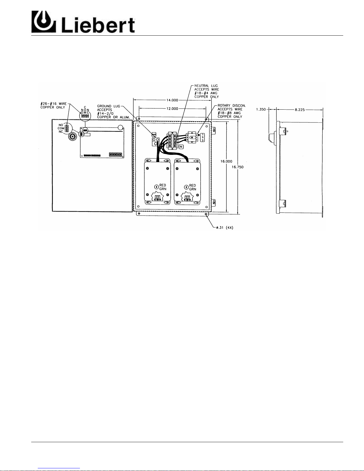
Figure 1. Cabinet Data, Form C Contact and Wiring
Surge
®
Suppression
Systems
LM, LM1, & LM2 Series Models with Options (Wt. 35 lbs.)
Figure 1. Cabinet Data, Form C Contact and Wiring
Installation, Operation - 4 - LM Series
and Maintenance Manual Rev 0, 5/99
 Loading...