

Page 1
Liebert Distribution Monitoring (LDM)
User Manual
AC Power
For Business-Critical Continuity™
Page 2

Page 3

TABLE OF CONTENTS
SAFETY INSTRUCTIONS . . . . . . . . . . . . . . . . . . . . . . . . . . . . . . . . . . . . . . . . . . . . . . . . . . . . . . . . .1
1.0 GLOSSARY OF ABBREVIATIONS . . . . . . . . . . . . . . . . . . . . . . . . . . . . . . . . . . . . . . . . . . . . .2
2.0 PRODUCT OVERVIEW . . . . . . . . . . . . . . . . . . . . . . . . . . . . . . . . . . . . . . . . . . . . . . . . . . . . . 3
3.0 MAJOR COMPONENTS . . . . . . . . . . . . . . . . . . . . . . . . . . . . . . . . . . . . . . . . . . . . . . . . . . . .4
3.1 Branch Circuit Monitoring Control Board (BCB). . . . . . . . . . . . . . . . . . . . . . . . . . . . . . . . . . . 4
3.2 Panel Board Voltage-Current Board (PBVI). . . . . . . . . . . . . . . . . . . . . . . . . . . . . . . . . . . . . . . 5
3.3 Large Interface Board (LIB) . . . . . . . . . . . . . . . . . . . . . . . . . . . . . . . . . . . . . . . . . . . . . . . . . . . 6
3.4 Branch Circuit Monitoring Sensor Module (BSM) . . . . . . . . . . . . . . . . . . . . . . . . . . . . . . . . . . 6
3.5 Power Supply Assembly (with EMI Filter) . . . . . . . . . . . . . . . . . . . . . . . . . . . . . . . . . . . . . . . . 6
4.0 INSTALLATION . . . . . . . . . . . . . . . . . . . . . . . . . . . . . . . . . . . . . . . . . . . . . . . . . . . . . . . . . .7
4.1 Installing a BSM (CT Module Assembly) . . . . . . . . . . . . . . . . . . . . . . . . . . . . . . . . . . . . . . . . . 7
4.1.1 Connecting Panelboards A and B . . . . . . . . . . . . . . . . . . . . . . . . . . . . . . . . . . . . . . . . . . . . . . . . 7
4.2 Installing a Solid-Core Current Transformer . . . . . . . . . . . . . . . . . . . . . . . . . . . . . . . . . . . . . . 8
4.3 Connecting a Current Transformer to the PBVI Board . . . . . . . . . . . . . . . . . . . . . . . . . . . . . . 9
4.4 CT Table for PBVI Board . . . . . . . . . . . . . . . . . . . . . . . . . . . . . . . . . . . . . . . . . . . . . . . . . . . . . 10
4.5 Connecting a Current Transformer to the LIB Board . . . . . . . . . . . . . . . . . . . . . . . . . . . . . . 12
4.6 CT Table for LIB. . . . . . . . . . . . . . . . . . . . . . . . . . . . . . . . . . . . . . . . . . . . . . . . . . . . . . . . . . . . 13
5.0 OPERATION . . . . . . . . . . . . . . . . . . . . . . . . . . . . . . . . . . . . . . . . . . . . . . . . . . . . . . . . . . .15
5.1 Alarms. . . . . . . . . . . . . . . . . . . . . . . . . . . . . . . . . . . . . . . . . . . . . . . . . . . . . . . . . . . . . . . . . . . . 16
5.2 Communication. . . . . . . . . . . . . . . . . . . . . . . . . . . . . . . . . . . . . . . . . . . . . . . . . . . . . . . . . . . . . 17
5.2.1 LDM Setup Port Connection . . . . . . . . . . . . . . . . . . . . . . . . . . . . . . . . . . . . . . . . . . . . . . . . . . . 17
5.2.2 Modbus Connection . . . . . . . . . . . . . . . . . . . . . . . . . . . . . . . . . . . . . . . . . . . . . . . . . . . . . . . . . . 17
5.3 Downloading the Software . . . . . . . . . . . . . . . . . . . . . . . . . . . . . . . . . . . . . . . . . . . . . . . . . . . . 18
5.4 Using the Monitor Tool . . . . . . . . . . . . . . . . . . . . . . . . . . . . . . . . . . . . . . . . . . . . . . . . . . . . . . 18
5.4.1 Starting the Monitor Tool . . . . . . . . . . . . . . . . . . . . . . . . . . . . . . . . . . . . . . . . . . . . . . . . . . . . . 18
5.4.2 Monitor Menu Options . . . . . . . . . . . . . . . . . . . . . . . . . . . . . . . . . . . . . . . . . . . . . . . . . . . . . . . . 19
5.4.3 Panel Status and Real-Time Clock . . . . . . . . . . . . . . . . . . . . . . . . . . . . . . . . . . . . . . . . . . . . . . 19
5.4.4 Main Breaker Status . . . . . . . . . . . . . . . . . . . . . . . . . . . . . . . . . . . . . . . . . . . . . . . . . . . . . . . . . 20
5.4.5 Breaker Status . . . . . . . . . . . . . . . . . . . . . . . . . . . . . . . . . . . . . . . . . . . . . . . . . . . . . . . . . . . . . . 20
5.4.6 Mode Buttons . . . . . . . . . . . . . . . . . . . . . . . . . . . . . . . . . . . . . . . . . . . . . . . . . . . . . . . . . . . . . . . 20
i
Page 4

5.5 Using the Configuration Tool . . . . . . . . . . . . . . . . . . . . . . . . . . . . . . . . . . . . . . . . . . . . . . . . . 21
5.5.1 Starting the Configuration Program . . . . . . . . . . . . . . . . . . . . . . . . . . . . . . . . . . . . . . . . . . . . . 21
5.5.2 Main Configuration Window Overview . . . . . . . . . . . . . . . . . . . . . . . . . . . . . . . . . . . . . . . . . . . 22
5.5.3 Load a Configuration File from Disk. . . . . . . . . . . . . . . . . . . . . . . . . . . . . . . . . . . . . . . . . . . . . 23
5.5.4 Install Configuration Changes in the Unit . . . . . . . . . . . . . . . . . . . . . . . . . . . . . . . . . . . . . . . . 23
5.5.5 Save the Configuration File to Disk . . . . . . . . . . . . . . . . . . . . . . . . . . . . . . . . . . . . . . . . . . . . . 23
5.5.6 Select Panel to View . . . . . . . . . . . . . . . . . . . . . . . . . . . . . . . . . . . . . . . . . . . . . . . . . . . . . . . . . . 24
5.5.7 Select Breakers to View . . . . . . . . . . . . . . . . . . . . . . . . . . . . . . . . . . . . . . . . . . . . . . . . . . . . . . . 24
5.5.8 Edit the Liebert LDM Unit Properties . . . . . . . . . . . . . . . . . . . . . . . . . . . . . . . . . . . . . . . . . . . 25
5.5.9 Edit the Panel Properties or Set a Password . . . . . . . . . . . . . . . . . . . . . . . . . . . . . . . . . . . . . . 25
5.5.10 Edit the Breaker Properties. . . . . . . . . . . . . . . . . . . . . . . . . . . . . . . . . . . . . . . . . . . . . . . . . . . . 26
5.5.11 Add or Delete a Circuit Breaker . . . . . . . . . . . . . . . . . . . . . . . . . . . . . . . . . . . . . . . . . . . . . . . . 27
5.5.12 Adding a Circuit Breaker . . . . . . . . . . . . . . . . . . . . . . . . . . . . . . . . . . . . . . . . . . . . . . . . . . . . . . 27
5.5.13 Adding a Subfeed Breaker . . . . . . . . . . . . . . . . . . . . . . . . . . . . . . . . . . . . . . . . . . . . . . . . . . . . . 28
5.5.14 Delete a Breaker . . . . . . . . . . . . . . . . . . . . . . . . . . . . . . . . . . . . . . . . . . . . . . . . . . . . . . . . . . . . . 29
5.6 Upgrading the Firmware . . . . . . . . . . . . . . . . . . . . . . . . . . . . . . . . . . . . . . . . . . . . . . . . . . . . . 30
6.0 SPECIFICATIONS. . . . . . . . . . . . . . . . . . . . . . . . . . . . . . . . . . . . . . . . . . . . . . . . . . . . . . . .33
7.0 TROUBLESHOOTING / FAQS . . . . . . . . . . . . . . . . . . . . . . . . . . . . . . . . . . . . . . . . . . . . . . . 34
TABLES
Table 1 CT matrix for the Liebert LDM . . . . . . . . . . . . . . . . . . . . . . . . . . . . . . . . . . . . . . . . . . . . . . . . . . . . . 5
Table 2 Wiring configuration of large branch circuit breakers . . . . . . . . . . . . . . . . . . . . . . . . . . . . . . . . . . 10
Table 3 Wiring configuration for LIB 1 . . . . . . . . . . . . . . . . . . . . . . . . . . . . . . . . . . . . . . . . . . . . . . . . . . . . . 13
Table 4 Wiring configuration for LIB2 . . . . . . . . . . . . . . . . . . . . . . . . . . . . . . . . . . . . . . . . . . . . . . . . . . . . . 14
Table 5 Parameters monitored for breakers. . . . . . . . . . . . . . . . . . . . . . . . . . . . . . . . . . . . . . . . . . . . . . . . . 15
Table 6 Alarm conditions and factory setpoints . . . . . . . . . . . . . . . . . . . . . . . . . . . . . . . . . . . . . . . . . . . . . . 16
Table 7 Monitor menu options. . . . . . . . . . . . . . . . . . . . . . . . . . . . . . . . . . . . . . . . . . . . . . . . . . . . . . . . . . . . 19
Table 8 Monitor mode buttons . . . . . . . . . . . . . . . . . . . . . . . . . . . . . . . . . . . . . . . . . . . . . . . . . . . . . . . . . . . . 20
Table 9 Overview of main Configuration window . . . . . . . . . . . . . . . . . . . . . . . . . . . . . . . . . . . . . . . . . . . . 22
ii
Page 5

SAFETY INSTRUCTIONS
WARNING
!
As with all types of electrical equipment, dangerous voltages exist within the equipment
where the Liebert Distribution Monitor (LDM) is installed. For maximum safety, ensure
power is removed and circuit breakers/disconnects are tagged/locked out per all applicable
national, state and local electrical codes prior to working inside equipment.
The area around the equipment must be free of any debris or standing water.
All power and control wiring must be installed by a qualified electrician in accordance with
the NEC and all applicable national, state and local codes.
ONLY qualified service personnel should perform maintenance and/or service on the Liebert
LDM. When performing maintenance and/or service on any component, verify test equipment
is insulated and has been inspected prior to use.
To avoid damage to the circuit boards, personnel handling these components should be
wearing an Electrostatic Discharge strap or other approved protective device.
When replacing or installing a solid core Current Transformer (CT), power must be removed
from equipment to prevent damage to the CT and/or circuit board. If the CT is a split-core
design, follow proper electrical safety procedures.
These safety precautions are to be used in conjunction with NEC and local/state electrical
code.
1
Page 6

1.0 GLOSSARY OF ABBREVIATIONS
The following abbreviations are used in this manual.
BCB Branch Circuit Monitoring Control Board
BCMS Branch Circuit Monitoring System
BMS Building Management System
BSM BCMS Sensor Module
DSP Digital Signal Processor
GUI Graphical User Interface
IGM Information Gathering Module
LDM Liebert Distribution Monitor
LIB Large Interface Board
OCWC OpenComms Web Card
PBVI Panelboard Voltage Current
PCD Power Conditioning Device
PDU Power Distribution Unit
STP Service Terminal Protocol
Glossary of Abbreviations
2
Page 7

2.0 PRODUCT OVERVIEW
The Liebert Distribution Monitor (LDM) monitors the main panelboard circuit breaker and individual
panelboard branch circuit breakers. The measurements are used to report the current and alarm conditions for each breaker. The Liebert LDM utilizes branch circuit sensor modules and individual current transformers (CT) to monitor current. In addition, the Liebert LDM monitors options like
subfeed and output circuit breakers and provides a full array of power parameters and alarms.
The Liebert LDM is available as an option for the Liebert PPC™ Precision Power Center, Liebert
FDC™, Liebert FPC™ and Liebert RDC™ Remote Distribution Cabinet.
Product Overview
The Liebert LDM system can communicate with a Building Management System (BMS) and Liebert
SiteScan
®
Web.
The Liebert LDM consists of a control board, panelboard voltage and current board, power supply
boards and sensor modules and can monitor two 42-pole panelboards and three subfeed breakers.
The Liebert LDM is capable of receiving input from 21-pole current sensor modules; two sensor modules are required to monitor one 42-pole panelboard. The sensor module (BSM) contains twenty-one
50A current transformers (CTs) capsulated in an epoxy-filled plastic enclosure designed to be
mounted next to the panelboard. Sensor modules are designed to work with Square D™ and GE panelboards. If a sensor module CT fails, connections are provided for up to six replacement CTs. The
optional CTs can be attached directly to the load cable feeding the failed CT.
For branch breakers larger than 50A, discrete 100A rated large branch current transformers can be
added. Higher-rated CTs can be used for monitoring optional subfeed circuit breakers. For subfeed
breakers, like main panelboard breakers, the Liebert LDM monitors not only the 3-phase current but
also the ground and neutral current. These subfeed circuit breakers are in addition to the 42 panelboard circuit breakers that can be monitored through the BSM. The Liebert LDM can accommodate
18 individual large current transformers.
If your Liebert power center is supplied with a Square D I-Line
®
panelboard, the Liebert LDM can
also monitor it as well as its output breakers. A large interface board (LIB) replaces the panelboard
voltage and current board and can monitor up to 42 poles. Each LIB can monitor eight 5-wire I-Line
and/or subfeed breakers including ground and neutral current. There can be 1 or 2 LIBs per control
board that can monitor a total of sixteen 5-wire I-Line and/or subfeed breakers.
The Liebert LDM has a Modbus port on the BCB for direct communication with a building management system (BMS). The Liebert LDM can communicate with Liebert SiteScan by using a Liebert
SiteLink™ communication device. A Liebert SiteLink-2E™ is available as an option with the Liebert
LDM and is mounted in the power center. Modbus Registry Summary documentation can be found at:
http://www.liebert.com/product_pages/ProductDocumentation.aspx?id=72
Click on the link for the Liebert Distribution Monitor (LDM Toolkit). Save the file to a desktop or laptop computer (PC) and extract the contents.
3
Page 8
3.0 MAJOR COMPONENTS
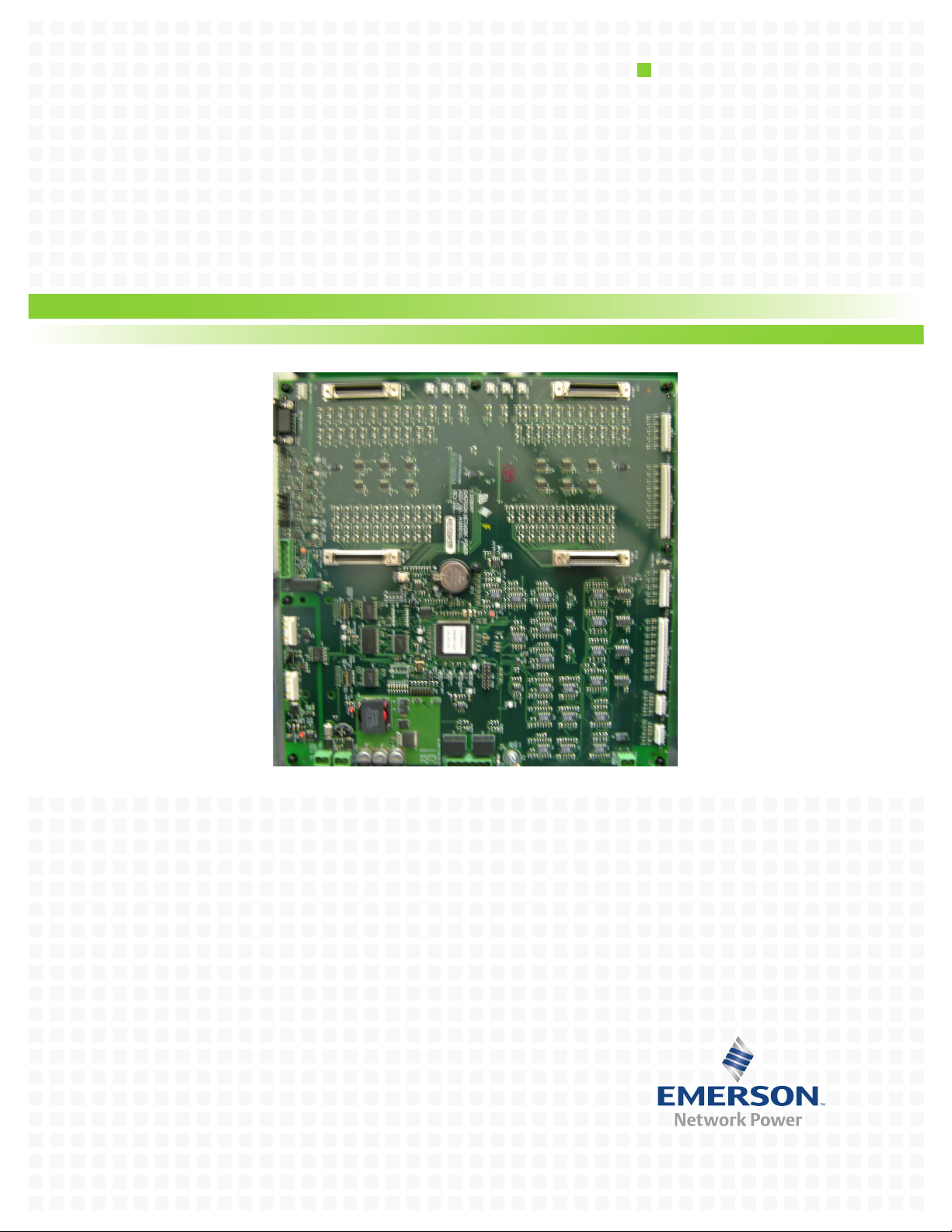
3.1 Branch Circuit Monitoring Control Board (BCB)
The BCB is the main processing and storage circuit board of the Liebert LDM. It is a DSP-based logic
controller with internal flash memory and non-volatile memory. The BCB also includes a batterybacked real time clock.
Major Components
One of the power parameters, kilowatt-hours (kWh)
board mains, subfeeds and each branch circuit breaker. A Modbus command is provided to reset all
accumulated power usage.
, data is accumulated on this board for the panel-
4
Page 9
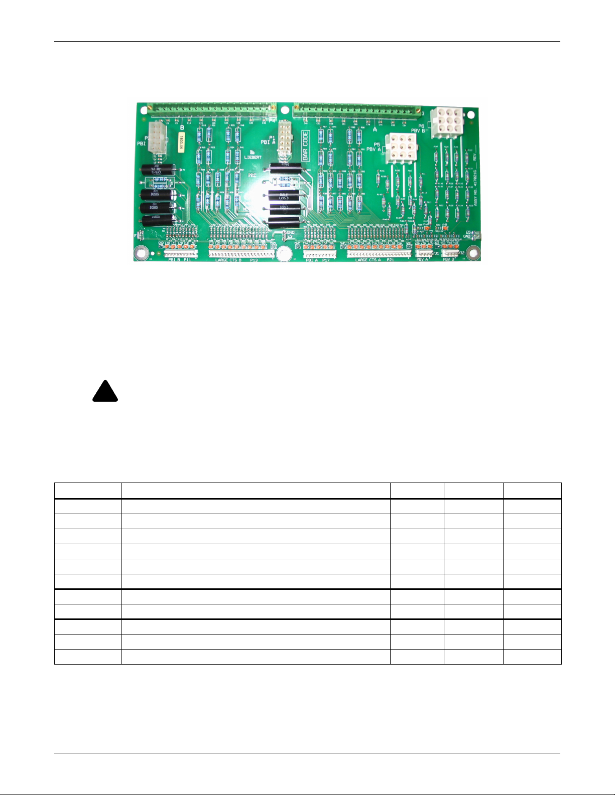
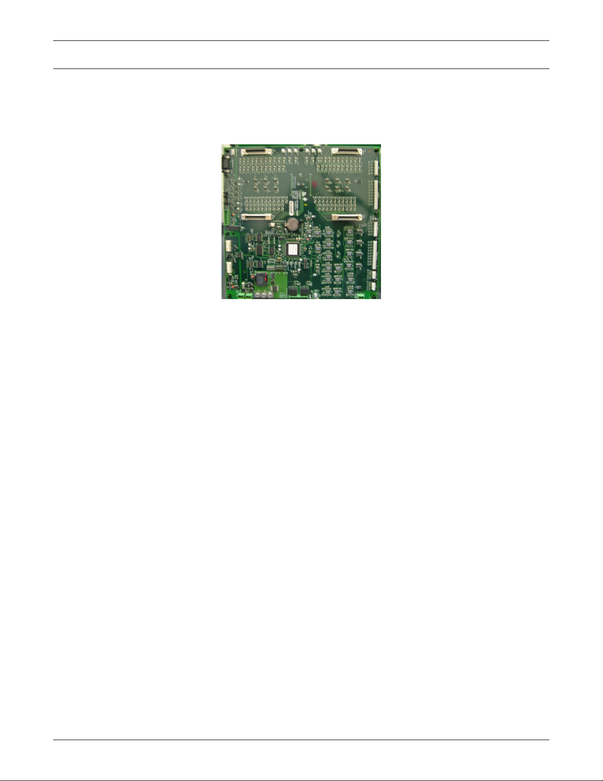
3.2 Panel Board Voltage-Current Board (PBVI)
The PBVI board monitors two panelboards and provides the voltage attenuators for the two panelboard voltages. The two sets of panelboard main breaker CTs are connected to the PBVI board.
Connections for the 18 large branch CTs are located on the PBVI board. The nine CTs on the A side of
the board are normally associated with the A-side voltages for power calculations. The B-side CTs are
normally associated with the B-side voltages. A cross-configuration tool allows changing that association for subfeeds.
Major Components
The 18 large branch CT inputs can also be used to monitor up to three subfeed circuit breakers. This
is configured using the Configuration tool (see 5.5 - Using the Configuration Tool). The CTs from
the B side of the PBVI are cross-configured to the A side so that the three sub-feeds appear within the
A-side panelboard register space. The 18 large branch breakers require CTs with 1A secondary.
WARNING
!
Before connecting a large CT to the PBVI board, note the CT MUST have 1A secondary.
Connecting a 5A secondary type CT will damage the board and the CT.
To ensure the proper current ratio and accuracy, the CTs should be purchased through
Emerson Network Power. See Table 1 for details. Contact your local Emerson Network
Power representative or call Liebert Services at 1-800-LIEBERT (1-800-543-2378).
Table 1 CT matrix for the Liebert LDM
Part Number Description Phase CT Ground CT Neutral CT
528415G1-L 3 pole 100A Subfeed Breaker 5W CT Kit 23" Frame 100:1 100:1 200:1
528415G2-L 3 pole 125-225A Subfeed Breaker 5W CT Kit 23" Frame 200:1 100:1 500:1
528415G3-L 3 pole 250-400A Subfeed Breaker 5W CT Kit 23" Frame 500:1 100:1 500:1
531461G6-L 3 pole 0-100A I-Line & Subfeed Breaker 5W CT Kit 47" Frame 200:1 100:1 200:1
531461G9-L 3 pole 125-225A I-Line & Subfeed Breaker 5W CT Kit 47" Frame 200:1 100:1 500:1
531461G12-L 3 pole 250-400A I-Line & Subfeed Breaker 5W CT Kit 47" Frame 500:1 100:1 500:1
531461G18-L 3 pole 0-225A I-Line Breaker 3W CT Kit 47" Frame 200:1 — —
531461G19-L 3 pole 250-400A I-Line Breaker 3W CT Kit 47" Frame 200:1 — —
528461G13-L 1 pole 0-100A Branch Breaker CT Kit 100:1 — —
528415G14-L 2 pole 0-100A Branch Breaker CT Kit 100:1 — —
528415G15-L 3 pole 0-100A Branch Breaker CT Kit 100:1 — —
5
Page 10
3.3 Large Interface Board (LIB)
The LIB provides the voltage attenuators for Square D I-Line panelboard
voltages. The LIB monitors the current for the I-Line panelboard. The
panelboard input CTs are connected to the LIB board. There are 42 CT
inputs provided. The current inputs require the use of 1A secondary CT.
WARNING
!
Before connecting a large CT to the PBVI board, note the CT
MUST have 1A secondary. Connecting a 5A secondary type CT
will damage the board and the CT.
To ensure the proper current ratio and accuracy, the CTs should
be purchased through Emerson Network Power. See Table 1 for
details. Contact your local Emerson Network Power
representative or call Liebert Services at 1-800-LIEBERT
(1-800-543-2378).
There can be up to two LIB boards per control board for a maximum total of sixteen 5-wire output
breakers.
3.4 Branch Circuit Monitoring Sensor Module (BSM)
The BSM—more commonly referred to as the CT Module—is packaged in an epoxy-filled plastic
assembly. There are two designs: one for 1" center-to-center GE panelboards and one for 3/4" centerto-center for Square D panelboards. Each contains twenty-one 50A CTs that are rated up to 50A RMS
50/60 Hz.
Major Components
NOTE
The diameter of each CT hole is 0.354" (9mm). Wire diameter and thickness of insulation
cannot be larger than the CT opening.
For the 42-breaker position in-line panel boards, the Square D CT Module is designed to interlock end
to end to maintain alignment between the breaker poles and the CT Module.
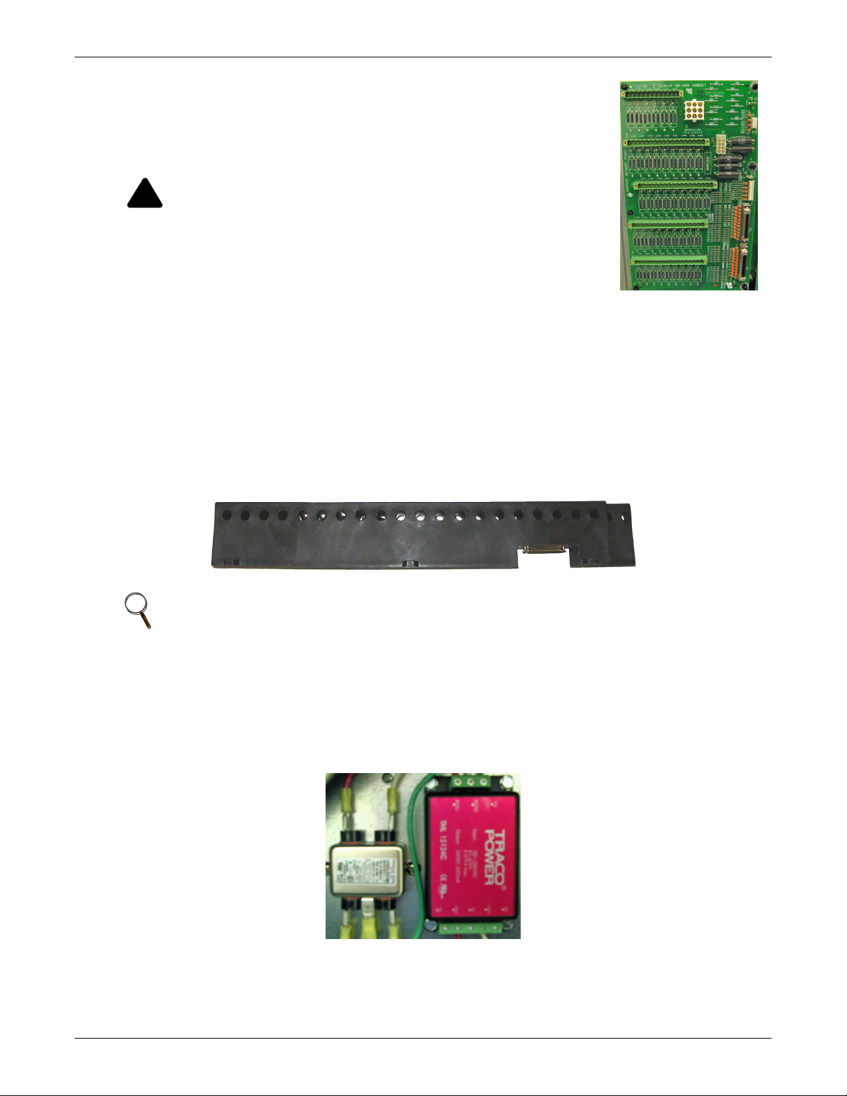
3.5 Power Supply Assembly (with EMI Filter)
The power supply assembly is 120-240VAC (range +6, -13%) 50/60 Hz input, 24VDC output to provide
logic level power for the BCB.
6
Page 11
4.0 INSTALLATION
WARNING
!
Dangerous voltages exist in power distribution units and power conditioning units. To ensure
maximum safety, all circuits breakers in the panelboard should be removed of power and the
input feeder breaker should be turned off and locked-out in accordance with NEC and local/
state code.
NOTE
Installation of Liebert LDM components or other monitoring devices should be performed by
qualified personnel only.
This section provides instructions for installing and connecting Liebert LDM current transformers. If
service needs to be performed on any Liebert LDM component, contact Emerson Network Power Liebert Services at 1-800-LIEBERT (1-800-543-2378) for assistance.
4.1 Installing a BSM (CT Module Assembly)
In most cases the BSM—the CT Module—is factory-installed and no further work is required. If you
need to add a CT Module, it attaches easily to the side of a panelboard to monitor any combination of
1-, 2- and 3-pole circuit breakers.
• For side-by-side panelboards (21 circuits on each side), attach one
CT Module to each side of the panelboard, ensuring that the center of
the CT hole lines up to the branch circuit breaker connection.
• For SqD Inline panelboards (42 circuits in a row), the two CT Modules must be interlocked to monitor 42 inline circuits. Flip the second,
lower CT Module so that the two cutout sections line up, then attach
the screws to secure the CT Modules to the panelboard.
• For GE Inline type panelboards, the two CT Modules fit end to end.
Flip the second, lower CT Module so that the 50-pin ribbon cable connector, mounted on the bottom of the CT Module, lines up with the hole
in the panelboard mounting bracket.
Installation
Install the circuit breakers according to the manufacturer’s documentation.
Route the circuit wire through the center of the CT and attach securely to
the circuit breaker.
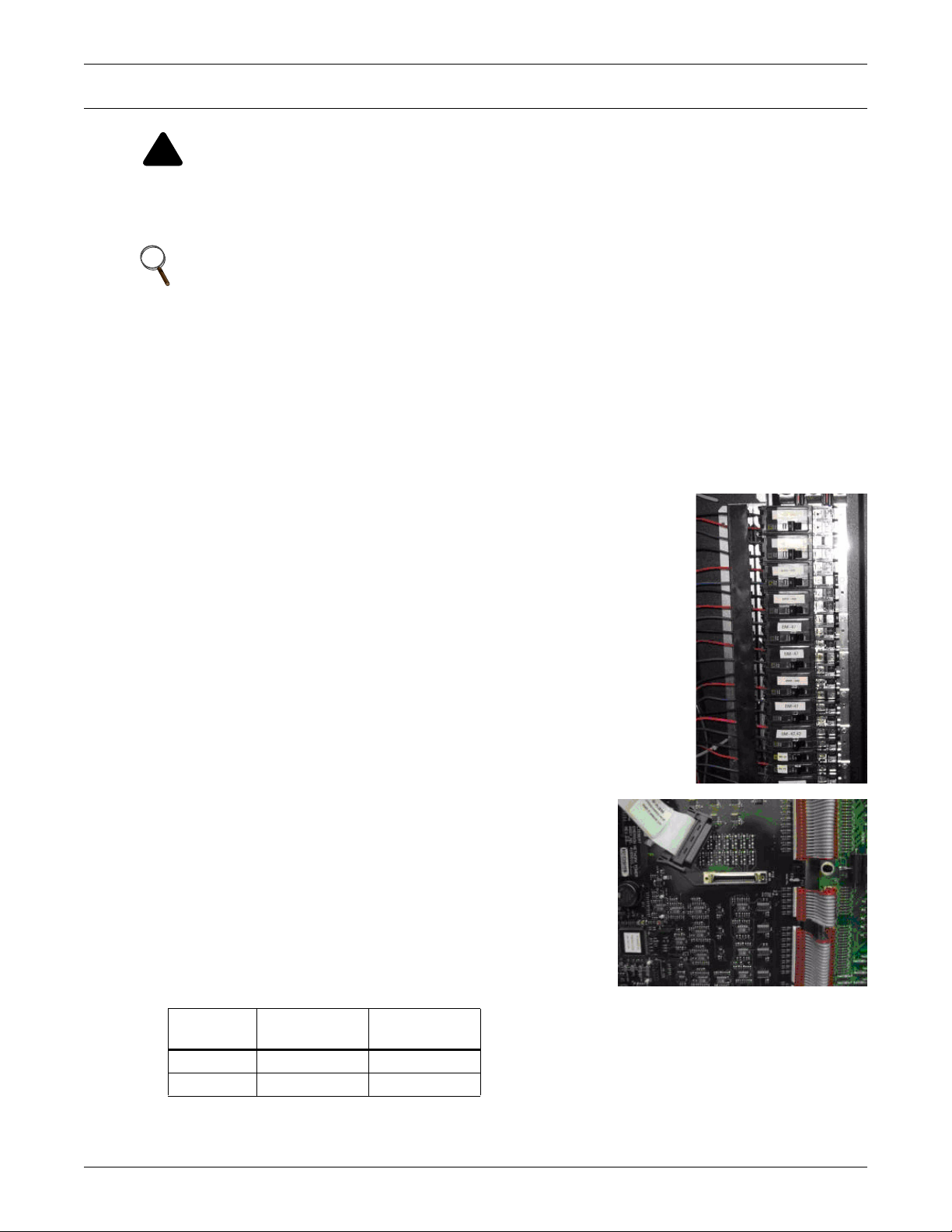
4.1.1 Connecting Panelboards A and B
The CT Module connects to the BCB via a 50-pin ribbon cable
attached to the back of the CT Module. Route the ribbon cable
and attach to the appropriate connector (see figure at right).
There are four connectors that are labeled for easy identification:
two for Panelboard A (A1 and A2) and two for Panelboard B
(B1 and B2).
• Connect the CT module that will monitor Circuits 1-21 to the
A1 or B1 connector, depending on whether the CT Module is
connected to Panelboard A or B.
• Connect the CT module that will monitor Circuits 22-42 to
the corresponding A2 or B2 connector.
Circuits
Monitored
1-21 A1 B1
22-42 A2 B2
To configure branch circuits, see 5.5.12 - Adding a Circuit Breaker.
Panelboard A
Connector
Panelboard B
Connector
7
Page 12
4.2 Installing a Solid-Core Current Transformer
WARNING
!
A solid-core CT cannot be installed on a wire while current is flowing through the wire.
Damage to burden resistor and CT will occur. Power needs to be removed prior to installing
and/or removing any CT. CTs should be installed by qualified electricians only.
The CT for the panelboard main input circuit breaker is hard-wired to the connectors. Removing CT
wires from the connector requires a pin extraction tool. Contact Liebert Services at 1-800-LIEBERT
(1-800-543-2378) for assistance.
Installation
NOTE
When replacing or installing a CT, ensure the replacement CT has a secondary rating of 1A—
for example, 100:1, 200:1 or 500:1. Using a higher-rated CT—for example, 100:5 or 500:5—will
damage the burden resistors on the PBVI board.
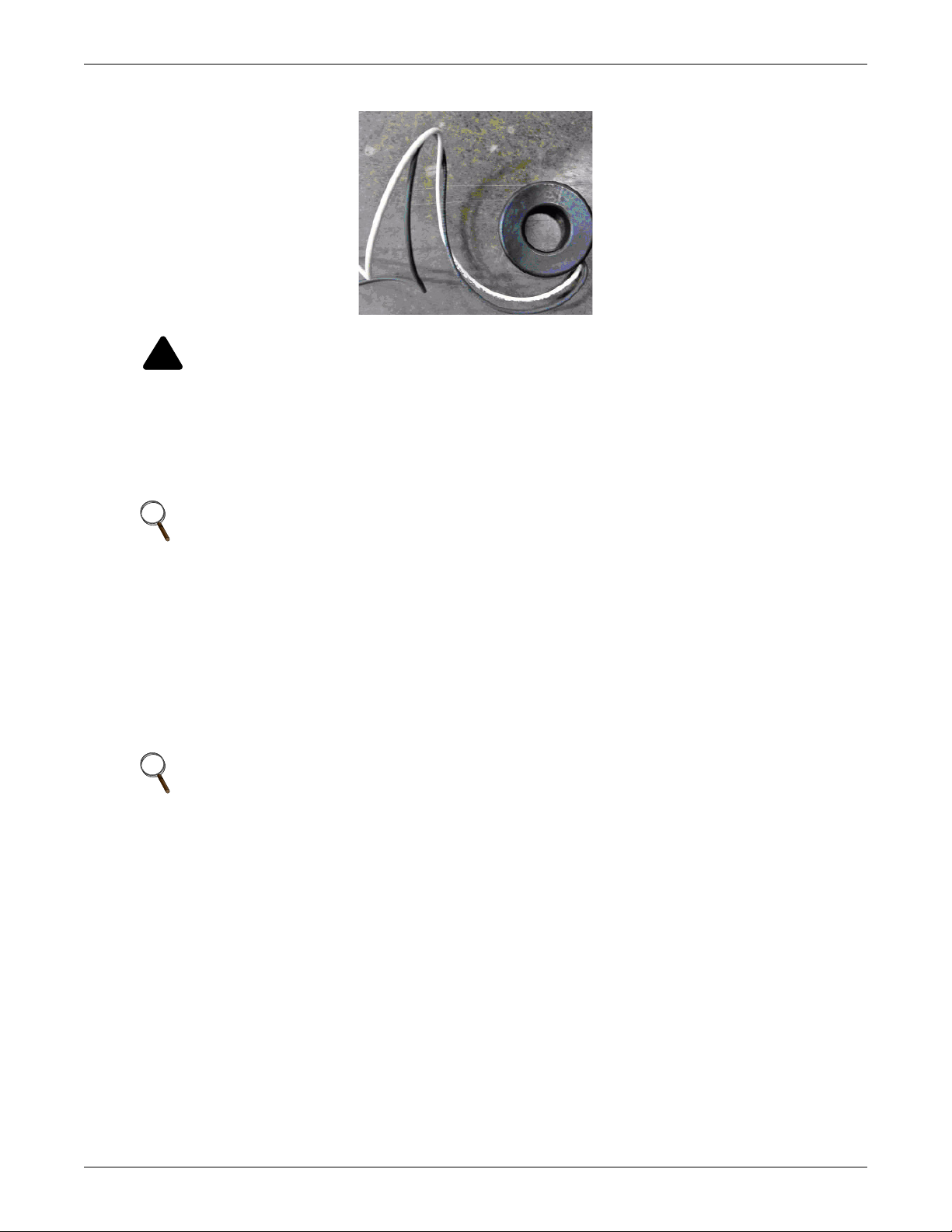
Typically the three-phase and neutral wires utilize a CT rating of 100:1, 200:1 or 500:1, while the
ground wire utilizes a CT rating of 100:1.
Route the circuit wire through the core of the CT and wire-tie the CT to the cable. Refer to the manufacturer’s documentation for proper orientation to ensure accurate readings. Generally, CTs have an
arrow, white dot or similar marking to indicate how to position the CT.
For the Liebert LDM, CTs have a white dot that must face the source on the three-phase wires and
must face the load on the neutral and ground wires.
NOTE
When installing CTs for a large branch circuit breaker or subfeed, verify which monitoring
board is installed.
• A PBVI board can support one subfeed per panelboard (if neutral and ground will be
monitored) or up to three subfeeds if neutral and ground are not monitored.
• One LIB can support up to eight output and/or subfeed breakers.
• Two LIB boards are provided to support up to 16 output and/or subfeed breakers.
8
Page 13

4.3 Connecting a Current Transformer to the PBVI Board
If subfeed breakers are ordered with the unit, the phase CTs are installed and wired to the PBVI. The
neutral and ground CTs are also factory-supplied and wired to the PBVI board.
Since the CTs must be installed on the subfeed breaker’s neutral and ground cables, they cannot be
installed in the factory. They are located in the bottom of the unit in front of the transformer.
CTs have an arrow, white dot or similar marking that depicts how to position the CT on the cable to
ensure accurate readings. The arrow, white dot or similar marking must face the load when installing
the CT on the ground and neutral cable. Route the neutral and ground cable through the core of the
CTs and wire-tie the CT to the cable.
If subfeed breakers are installed in the field, up to five CTs may be installed to monitor a subfeed
breaker (three phases, neutral and ground). The neutral and ground CTs may be omitted if monitoring of neutral and ground is not required.
On large branch circuit breakers, ground and neutral is not monitored.
There are two 18-pin terminal blocks on the PBVI for large branch circuit breakers and/or subfeeds—
one for Panelboard A and one for Panelboard B.
The circuit board is marked with a triangle to indicate Pin 1.
• Pin 1 should be used for the white wire of CT1 (Phase A)
• The black wire should be connected to Pin 2.
• The same pattern will follow for the remaining CTs.
After all CTs are installed, use the Configuration tool to label and set alarm parameters. To configure
the Liebert LDM, see 5.5.11 - Add or Delete a Circuit Breaker.
If the Power Distribution Center is supplied with optional isolated ground, the isolated ground circuit
can be monitored by the Liebert LDM.
• Connect the isolated ground CT to Pins 17 and 18 on the two 18-pin terminal blocks on the PBVI.
• Connect the isolated ground CT white wire to Pin 17 and the CT black wire to Pin 18.
▼
Installation
CTs for the
three phases
CT for neutral
and ground
Five CT
connection
Refer to the following example and Table 2 for wiring configuration details.
Example: When installing a subfeed breaker where the three phases, neutral and ground will be
monitored, the CTs should be wired as follows:
Pin Wiring
1 Phase A CT White wire
2 Phase A CT Black wire
3 Phase B CT White wire
4 Phase B CT Black wire
5 Phase C CT White wire
6 Phase C CT Black wire
7 Neutral CT White wire
8 Neutral CT Black wire
9 Ground CT White wire
10 Ground CT Black wire
If neutral and ground will not be monitored, Pins 7-10 may be used instead for a second subfeed
(Phase A and Phase B CTs).
9
Page 14

4.4 CT Table for PBVI Board
Table 2 shows the configuration of large branch circuit breakers and their CT assignments.
Table 2 Wiring configuration of large branch circuit breakers
Configuration 1: Four Modules
Connector P3 (A) Pins
Wire Color WBWBWBWBWBWBWBWBWB
CT CT1 CT2 CT3 CT4 CT5 CT6 CT7 CT8
Connector P4 (B) Pins
Wire Color WBWBWBWBWBWBWBWBWB
CT CT10 CT11 CT12 CT13 CT14 CT15 CT16 CT17
Configuration 2: Two Modules With Large Branch Breaker CTs
Connector P3 (A) Pins
Wire Color WBWBWBWBWBWBWBWBWB
CT LB1 LB2 LB3 LB4 LB5 LB6 LB7 LB8
Connector P4 (B) Pins
Wire Color WBWBWBWBWBWBWBWBWB
CT LB10 LB11 LB12 LB13 LB14 LB15 LB16 LB17
▼
1 2 3 4 5 6 7 8 9 10 11 12 13 14 15 16 17 18
▼
1 2 3 4 5 6 7 8 9 10 11 12 13 14 15 16 17 18
▼
1 2 3 4 5 6 7 8 9 10 11 12 13 14 15 16 17 18
▼
1 2 3 4 5 6 7 8 9 10 11 12 13 14 15 16 17 18
Installation
CT9
or IG
CT18
or IG
LB9
or IG
LB18
or IG
Configuration 3: Four Modules With Two 5-Wire Subfeed Breaker CTs
▼
Connector P3 (A) Pins
1 2 3 4 5 6 7 8 9 10 11 12 13 14 15 16 17 18
Wire Color W B W B W B W B W B
CT LB1 LB2 LB3 LB4 LB5 IG
Phase A1 B1 C1 N1 G1
▼
Connector P4 (B) Pins
1 2 3 4 5 6 7 8 9 10 11 12 13 14 15 16 17 18
Wire Color W B W B W B W B W B
CT LB6 LB7 LB8 LB9 LB10 IG
Phase A2 B2 C2 N2 G2
Configuration 4: Four Modules With Three 5-Wire Subfeed Breaker CTs
▼
Connector P3 (A) Pins
1 2 3 4 5 6 7 8 9 10 11 12 13 14 15 16 17 18
Wire Color WBWBWBWBWBWBWBWBWB
CT LB1 LB2 LB3 LB4 LB5 LB11 LB12 IG
Phase A1 B1 C1 N1 G1 N3 G3
▼
Connector P4 (B) Pins
1 2 3 4 5 6 7 8 9 10 11 12 13 14 15 16 17 18
Wire Color W B W B W B W B W B W B W B
CT LB6 LB7 LB8 LB9 LB10 LB11 LB12 LB13 IG
Phase A2 B2 C2 N2 G2 A3 B3 C3
W = White
B = Black
IG = Isolated Ground CT
LB = Large Branch Breaker CT
A = A Phase CT
B = B Phase CT
C = C Phase CT
N = Neutral CT
G = Ground CT
10
Page 15

Table 2 Wiring configuration of large branch circuit breakers (continued)
Configuration 5: Four Modules With Six 3-Wire Subfeed Breaker CTs
Connector P3 (A) Pins
Wire Color WBWBWBWBWBWBWBWBWB
CT LB1 LB2 LB3 LB4 LB5 LB6 LB7 LB8 LB9
Phase A1 B1 C1 A2 B2 C2 A3 B3 C3
Connector P4 (B) Pins
Wire Color WBWBWBWBWBWBWBWBWB
CT LB10 LB11 LB12 LB13 LB14 LB15 LB16 LB17 LB18
Phase A4 B4 C4 A5 B5 C5 A6 B6 C6
Configuration 6: Three Modules With Nine Large Branch Breaker CTs
Connector P3 (A) Pins
Wire Color WBWBWBWBWBWBWBWBWB
CT LB1 LB2 LB3 LB4 LB5 LB6 LB7 LB8
Connector P4 (B) Pins
▼
1 2 3 4 5 6 7 8 9 10 11 12 13 14 15 16 17 18
▼
1 2 3 4 5 6 7 8 9 10 11 12 13 14 15 16 17 18
▼
1 2 3 4 5 6 7 8 9 10 11 12 13 14 15 16 17 18
▼
1 2 3 4 5 6 7 8 9 10 11 12 13 14 15 16 17 18
Installation
LB9
or IG
W = White
B = Black
IG = Isolated Ground CT
LB = Large Branch Breaker CT
A = A Phase CT
B = B Phase CT
C = C Phase CT
N = Neutral CT
G = Ground CT
11
Page 16

4.5 Connecting a Current Transformer to the LIB Board
LIB can monitor eight 5-wire output/subfeed breakers. Two LIB boards are provided to support up to
16 output and/or subfeed breakers. If subfeed breakers are ordered with the unit, the phase CTs are
installed and wired to the LIB. The neutral and ground CTs are also factory-supplied and wired to the
LIB.
Since the CTs must be installed on the subfeed breaker’s neutral and ground cables, they cannot be
installed in the factory. They are located in the bottom of the unit in front of the transformer.
CTs have an arrow, white dot or similar marking that depicts how to position the CT to ensure accurate readings. The arrow, white dot or similar marking must face the load when installing the CT on
the ground and neutral cable. Route the neutral and ground cable through the core of the CTs and
wire-tie the CT to the cable.
If subfeed breakers are installed in the field, up to five CTs may be installed to monitor a subfeed
breaker (three phases, neutral and ground). The neutral and ground CTs may be omitted if monitoring of neutral and ground is not required.
The designators on the LIB are different from those on the PBVI board.
• CT1 (Phase A white wire) begins on TB1 CT1+ and the black wire connects to CT1-.
• The Ground CT for the first subfeed/output circuit breaker connects to TB4 CT35.
Installation
Four CTs
(three phases
and neutral)
Ground CT
Refer to the example below and Tables 3 and 4 for wiring configuration details.
Example: The above pictures show how to install CTs for a subfeed or I-Line output circuit breaker
with neutral and ground being monitoring. The CTs should be wired as follows:
First Breaker Second Breaker
CT1+ Phase A CT White wire CT5+ Phase A CT White wire
CT1- Phase A CT Black wire CT5- Phase A CT Black wire
CT2+ Phase B CT White wire CT6+ Phase B CT White wire
CT2- Phase B CT Black wire CT6- Phase B CT Black wire
CT3+ Phase C CT White wire CT7+ Phase C CT White wire
CT3- Phase C CT Black wire CT7- Phase C CT Black wire
CT4+ Neutral CT White wire CT8+ Neutral CT White wire
CT4- Neutral CT Black wire CT8- Neutral CT Black wire
CT35+ Ground CT White wire CT36+ Ground CT White wire
CT35- Ground CT Black wire CT36- Ground CT Black wire
If more output or subfeed CTs need to be installed, continue in the same pattern shown above.
• Connect the Phase A CT for the second breaker on CT5 (white wire to CT5+, black to CT5-).
• Connect the Ground CT for the second breaker to CT36 (white wire to CT36+, black to CT36-).
• Continue the same pattern until all CT connections are used or there are no more output or subfeed CTs to add.
12
Page 17

4.6 CT Table for LIB
Tables 3 and 4 show the CT assignments for 10 output breaker CTs and three subfeed breaker CTs
with neutral and ground being monitored.
Table 3 Wiring configuration for LIB 1
Pins 181716151413121110987654321
Connector
TB1
Connector
TB2
Connector
TB3
Wire Color BWBWBWBWBWBWBWBWBW
CT CT9 CT8 CT7 CT6 CT5 CT4 CT3 CT2 CT1
Phase A3 N2 C2 B2 A2 N1 C1 B1 A1
Pins 181716151413121110987654321
Wire Color BWBWBWBWBWBWBWBWBW
CT CT18 CT17 CT16 CT15 CT14 CT13 CT12 CT11 CT10
Phase B5 A5 N4 C4 B4 A4 N3 C3 B3
Pins 181716151413121110987654321
Wire Color BWBWBWBWBWBWBWBWBW
CT CT27 CT26 CT25 CT24 CT23 CT22 CT21 CT20 CT19
Phase C7 B7 A7 N6 C6 B6 A6 N5 C5
-+-+-+-+-+-+-+-+-+
-+-+-+-+-+-+-+-+-+
-+-+-+-+-+-+-+-+-+
Installation
Connector
TB4
Connector
TB5
W = White
B = Black
Pins 181716151413121110987654321
-+-+-+-+-+-+-+-+-+
Wire Color BWBW BWBWBWBWBW
CT CT2 CT1 NONE NONE CT32 CT31 CT30 CT29 CT28
Phase G2 G1 N8 C8 B8 A8 N7
Pins 121110987654321
-+-+-+-+-+-+
Wire Color BWBWBWBWBWBW
CT CT8 CT7 CT6 CT5 CT4 CT3
Phase G8 G7 G6 G5 G4 G3
A = A Phase
B = B Phase
C = C Phase
N = Neutral
G = Ground
13
Page 18

Table 4 Wiring configuration for LIB2
Pins 18 17 16151413121110987654321
Connector
TB1
Connector
TB2
Connector
TB3
Wire Color B W B W B W B W B WBWBWBWBW
CT CT41 CT40 CT39 CT38 CT37 CT36 CT35 CT34 CT33
Phase A11 N10 C10 B10 A10 N9 C9 B9 A9
Pins 18 17 16151413121110987654321
Wire Color B W B W B W B W B WBWBWBWBW
CT CT50 CT49 CT48 CT47 CT46 CT45 CT44 CT43 CT42
Phase B13 A13 N12 C12 B12 A12 N11 C11 B11
Pins 18 17 16151413121110987654321
Wire Color B W B W B W B W B WBWBWBWBW
CT NONE NONE NONE NONE NONE NONE NONE CT52 CT51
Phase N13 C13
- + - + - + - + - +-+-+-+-+
- + - + - + - + - +-+-+-+-+
- + - + - + - + - +-+-+-+-+
Installation
Connector
TB4
Connector
TB5
W = White
B = Black
Pins 18 17 16151413121110987654321
- + - + - + - + - +-+-+-+-+
Wire Color B W B W B WBWBWBWBW
CT CT10 CT9 NONE NONE NONE NONE NONE NONE NONE
Phase G10 G9
Pins 121110987654321
- + -+-+-+-+-+
Wire Color B W BWBWBWBWBW
CT NONE NONE NONE CT13 CT12 CT11
Phase G13 G12 G11
A = A Phase
B = B Phase
C = C Phase
N = Neutral
G = Ground
14
Page 19

Operation
5.0 OPERATION
The Liebert LDM is a factory-installed option to provide monitoring of the main breaker, branch circuit breakers and subfeed breakers. It may be installed in the Liebert PPC Precision Power Center,
Liebert FDC, Liebert FPC and Liebert RDC Remote Distribution Cabinet.
Software available on Liebert’s Web site (see 5.3 - Downloading the Software) can be installed on a
desktop or laptop computer (PC) to monitor status and configure breaker parameters and alarm setpoints. These monitoring and configuration functions are described in 5.4 - Using the Monitor Tool
and 5.5 - Using the Configuration Tool.
The Liebert LDM monitors and displays the parameters listed in Table 5.
Table 5 Parameters monitored for breakers
Displayed and monitored for each:
Panelboard
Parameters
Voltage — ✔ ——
Line-to-line — ✔ ——
Line-to-neutral — ✔ ——
Phase Current ✔✔✔✔
Neutral Current — ✔✔✔
Ground Current — ✔✔✔
kVA — ✔✔✔
kW ✔✔✔✔
kW-Hours ✔✔✔✔
Percent Load ✔✔✔✔
Power Factor — ✔✔✔
Crest Factor — ✔✔✔
Voltage Total Harmonic Distortion (THD) — ✔✔✔
Current Total Harmonic Distortion (THD) — ✔✔✔
branch
circuit breaker
Panelboard main
circuit breaker and
SqD I-Line panelboard
SqD I-Line
panelboard
circuit breaker
Subfeed
circuit
breaker
Circuit identification and status of each breaker are also displayed. Parameters are updated every
500msec.
15
Page 20

Operation
5.1 Alarms
The Liebert LDM constantly monitors configured parameters for normal values. When the unit
detects an alarm condition, it annunciates and displays alarm messages via the Monitor program (see
5.4 - Using the Monitor Tool).
Alarms must be manually reset after the alarm condition has been corrected and may be reset
through Modbus.
To facilitate troubleshooting:
• All alarms are stored in non-volatile memory to protect against erasure by a power outage.
• Alarms are saved in an event log. The event log stores up to 128 events using a first-in, first-out
format (FIFO).
All alarm thresholds for monitored parameters are adjustable by using the Configuration tool to
match site requirements (see 5.5 - Using the Configuration Tool).
Table 6 shows the types of alarms for the various types of breakers, along with a description, factory
default setpoints and allowable range for each.
Table 6 Alarm conditions and factory setpoints
Alarm Description Default setting Range
Branch Breakers
• Overcurrent Warning Current exceeds 75% of breaker amps 15A 0-75%
• Overcurrent Alarm Current exceeds 80% of breaker amps 16A 10-80%
0%, which
• Low Current Alarm Minimum current level of a branch breaker
Panelboard Main Breaker and SqD I-Line Panelboard
• Phase Overcurrent Warning Current exceeds 75% of breaker amps 170A 0-75%
• Phase Overcurrent Alarm Current exceeds 80% of breaker amps 180A 10-80%
• Neutral Overcurrent Alarm Current exceeds 95% of breaker amps 214A 10-200%
• Ground Overcurrent Alarm Current exceeds 5 amps 5A 1-50A
• Overvoltage Alarm
• Undervoltage Alarm
Subfeed Breakers and I-Line Output Breakers
• Phase Overcurrent Warning Current exceeds 75% of breaker amps 170A 0-75%
• Phase Overcurrent Alarm Current exceeds 80% of breaker amps 180A 10-80%
• Low Current Warning Minimum current level of a branch breaker
• Neutral Overcurrent Alarm Current exceeds 95% of breaker amps 214A 10-200%
• Ground Overcurrent Alarm Current exceeds 5 amps 5A 1-50A
Summary Alarm Detects and annunciates upon occurrence of any alarm — —
Panelboard Summary Alarm
At least one of the line-to-line voltages exceeds +6% of
nominal
At least one of the line-to-line or line-to-neutral voltages
falls below -13% of nominal
Detects and annunciates upon occurrence of branch or
panelboard main breaker alarm
disables
the alarm
— 0-50%
— 0-50%
0%, which
disables
the alarm
——
0-70%
0-70%
16
Page 21

5.2 Communication
5.2.1 LDM Setup Port Connection
Use the LDM Setup port to download and use the software from Liebert’s Web site for monitoring,
configuration and firmware upgrades (see 5.3 - Downloading the Software). This port is not a terminal interface.
To connect to the LDM Setup port:
• Connect one end of a standard DB9 (female-female) null modem cable to a desktop or laptop computer (PC).
• Connect the other end of the cable to the LDM Setup port on the Liebert LDM, as shown below.
NOTE
The images above are intended for illustration only. The location of the external port may vary.
Operation
5.2.2 Modbus Connection
Use the Modbus port for remote communication. The Liebert LDM supports 2- or 4-wire RS-485/422
connection (customer-installed).
To connect to the Modbus port:
• Look for Connector TB1 on the BCB. This is the RS-485 Modbus port.
• Refer to the following figure for proper connection points.
NOTE
The triangle printed on the circuit board depicts Pin 1.
Triangle
indicates
Pin 1
Pin 5 = TX+
Pin 4 = TX-
Pin 3 = TX+/RX+
Pin 2 = RX-/TX-
Pin 1 = Shield
17
Page 22

5.3 Downloading the Software
The Liebert LDM has three software tools for monitoring, configuration and firmware updates:
• Monitoring - see 5.4 - Using the Monitor Tool
• Configuration - see 5.5 - Using the Configuration Tool
• Firmware updates - see 5.6 - Upgrading the Firmware
These programs may be downloaded at no charge or license fee at Liebert’s Web site at:
http://www.liebert.com/product_pages/ProductDocumentation.aspx?id=72
NOTE
The software may be updated and changed without any notification. Check the Web site
regularly to ensure the software is up-to-date.
5.4 Using the Monitor Tool
The Monitor tool supports service terminal connections through the LDM Setup port. The tool displays the following information:
• Main input voltage and currents
• Total power
• Individual branch circuit breaker currents
•Event log
• System clock (date and time)
• Reset kWh function
Operation
A special registry key may be installed in the PC to enable the auto-zero control option and provide
access to a more in-depth event log. This diagnostic feature is reserved for use by Liebert Services and
Emerson Network Power technical personnel.
5.4.1 Starting the Monitor Tool
• If needed, download the latest version of the software (see 5.3 - Downloading the Software).
• Run the executable file Monitor-xx.exe (where xx is the latest version) to start the Monitor tool.
• In the Connect window, select the appropriate COM port, shown below left. The dialog box lists
available ports only. If a port is in use, it does not appear in the list.
•Click Connect.
• The Monitoring main window, below right, opens after communication is established.
COM port
Connect
18
Page 23

5.4.2 Monitor Menu Options
The Monitor window has a menu bar at the top with a drop-down list of options for each menu.
Table 7 summarizes the options available in these menus.
Table 7 Monitor menu options
Menu Option Function
File Menu
• Exit Terminates the monitoring session and closes the Monitor program.
View Menu
• Event Logs Opens the Event Log window, allowing users to view a list of events for Panel A or Panel B or
system. Events are listed in order of occurrence, starting with the most recent.
• Breakers Updates the status of all branch breakers for the selected panel in the Breaker Status area.
• Subfeeds Updates the status of all subfeed breakers for the selected panel in the Breaker Status area.
Dump Menu
• Readings Downloads a .csv file with main breaker, branch circuit breaker and subfeed readings. The file
may be viewed with a spreadsheet program such as Microsoft Excel.
• Event Log Downloads a .csv file with the event log stored on the BCB. The file may be viewed with a
spreadsheet program such as Microsoft Excel.
• Configuration Downloads a .txt file with the configuration file stored on the BCB. The file includes scaling data,
Panelboard A and B configurations, branch circuit values and CT ratio settings.
Alarms Menu
Choose one of three options—Raw, Filtered or Latched—to specify how alarms are displayed.
Note that alarms sent over Modbus are latched independent of changes performed in the Alarms menu.
• Raw The raw alarm state is the instantaneous state of the alarm. It is not filtered and has no
hysteresis. When Raw is selected, an alarm is active whenever the latest reading exceeds the
setpoint and is cleared as soon as the reading returns to a level within the setpoint range.
• Filtered The filtered alarm uses the hysteresis interval to suppress transient alarms. A filtered alarm is
cleared after the alarm condition remains cleared for longer than the hysteresis interval.
• Latched Latched alarms behave like filtered alarms that get stuck on. A latched alarm stays active until
the alarm is manually cleared.
• Clear All Clears all latched alarms for the selected panel. Any alarm condition that is still active is latched
again after the hysteresis interval passes.
Help Menu
• About Displays information about Liebert Distribution Monitoring.
Operation
Menu options
5.4.3 Panel Status and Real-Time Clock
The Panel Status area displays:
• The name of the Liebert LDM in the Unit box.
• The currently selected panel in the Panel box.
To choose a different panel, click on the panel name or the A/B button. If the selected panel has
any active alarms, the panel name appears in white text with a red background.
The Real-Time Clock displays the time as stored in the Liebert LDM unit. The time will not display
correctly if the time zone is incorrect in the PC. If the time displayed is incorrect and the problem is
not caused by a time-zone configuration problem:
•Click the Set button to force the real-time clock to synchronize with the time set on the PC.
19
Page 24

5.4.4 Main Breaker Status
The Main Breaker Status area displays RMS current, percent load (PCT), total harmonic distortion
(THD), crest factor (CF), line-to-line voltage (VLL-RMS), line-to-neutral voltage (VLN-RMS), instantaneous power (Power), VA and power factor (PF) for each input phase. If any phase voltage or current is in alarm, the associated field displays white text with a red background.
The metered energy usage for the panel is also displayed in kilowatt hours (kWh), as shown above. To
clear all metering information, click the Reset All kWh button.
CAUTION
!
Exercise care before using the Reset All kWh button, which resets the kWh usage for the
main breaker as well as all branch breakers and subfeed breakers on the panel.
5.4.5 Breaker Status
The Breaker Status area displays detailed status for every branch or subfeed breaker on the selected
panel. The information may appear in a table or as icons, depending on the whether the Table or
Icons button is active (see 5.4.6 - Mode Buttons).
Operation
Metered energy usage for the panel
The example below shows the table format with details for each breaker: type and rating, percent
load, individual phase current in amps (I1, I2, I3), power, apparent power (VA), power factor (PF) and
accumulated kilowatt hours (kWh.)
5.4.6 Mode Buttons
Mode buttons at the bottom of the Monitor window allow users to download Monitor readings to a file,
toggle the display between branch and subfeed breakers, toggle between table and icon views of
breaker status data and view the Event Log. Additionally, Emerson Network Power technical personnel may control the auto-zero function if the diagnostic registry key is installed.
Table 8 Monitor mode buttons
Button Function
Dump Converts the Monitor readings into a spreadsheet format (.csv file format).
Subfeeds/Breakers
Icons/Table
Events Displays the Event Log dialog box.
Auto-Zero
(not shown above)
Subfeeds/Breakers
button
Toggles between the subfeed and branch breaker displays. The button label changes
when the display is changed.
Toggles between the tabular and icon views. The button label changes when the display is
changed.
Viewable only if the diagnostic registry key has been installed on the PC. Used by Emerson
Network Power technical personnel for diagnostic purposes only.
Icons/Table
button
20
Page 25

5.5 Using the Configuration Tool
The Configuration tool allows users to set up breakers and view or change their parameters and
alarm setpoints.
NOTE
End users are unable to create a configuration file. Only Emerson Network Power technical
personnel can create a unique configuration file. Please contact your local Emerson Network
Power representative or call Liebert Services at 1-800-LIEBERT (1-800-543-2378) for
assistance.
5.5.1 Starting the Configuration Program
Before starting the Configuration tool, make sure you have the most recent version of the software
and decide whether you want to connect to the Liebert LDM or work in offline mode.
Offline mode allows you to run the configuration tool without being connected to the equipment.
(Prior to Version 25—LDM-Config-25—a service terminal connection was required to configure or
monitor the Liebert LDM.)
NOTE
A configuration file is required for Offline Mode. If one is not available, connect to the
equipment locally and save the configuration to disk. See 5.5.4 - Install Configuration
Changes in the Unit and 5.5.5 - Save the Configuration File to Disk.
To Connect via COM Port To Work in Offline Mode
1. If needed, download the latest version of the
software (see 5.3 - Downloading the
Software).
2. Connect a PC to the Liebert LDM via the external
DB9 connection. Refer to 5.2.1 - LDM Setup
Port Connection.
3. Run the file LDM-Config-xx.exe (where xx is
the version number) to start the Configuration
program.
4. In the Connect window, select the appropriate
COM port from the list of available ports.
5. Click Connect.
Operation
1. If needed, download the latest
version of the software (see 5.3 -
Downloading the Software).
2. Run the file LDM-Config-xx.exe
(where xx is the version number) to
start the Configuration program.
3. In the Connect window, click the
Work Offline button, shown below.
4. When prompted for the
configuration file, navigate to the
location of the file.
5. Click Open.
COM port
Proceed to 5.5.2 - Main Configuration Window Overview to begin configuration.
When a local connection to the Liebert LDM can be performed, load the configuration using the
instructions in 5.5.3 - Load a Configuration File from Disk.
21
Work Offline
Page 26

5.5.2 Main Configuration Window Overview
The Configuration window shows breakers graphically in the left pane and associated breaker data at
right. Selecting a breaker in the left pane changes the display of data in the right pane.
Operation
Select Panel
Select View
Unit
Properties
Panel
Properties
Breaker
Properties
Mode
buttons
Table 9 shows the main sections of the window, along with a description and a reference to step-bystep instructions for each.
Table 9 Overview of main Configuration window
Section Function For details, see:
Select Panel Toggles the display between Panel A and Panel B. 5.5.6 - Select Panel to View
Select View Toggles between Panel and Auxiliary Breakers. 5.5.7 - Select Breakers to View
Unit Properties
Panel Properties
Breaker Properties Displays breaker parameters and alarm setpoints. 5.5.10 - Edit the Breaker Properties
Configuration Mode Buttons
• Load from File
• Install to Unit
• Save to File
• Exit Now Closes the Configuration program. —
Displays the name, DIP switch address and
software address of the Liebert LDM unit.
Displays the name of the selected panelboard; also
password setup for security purposes.
Uploads a saved configuration file from the PC to
the Liebert LDM.
This feature may be used to install a backup copy
of a configuration file or set up a new Liebert LDM
installation.
Uploads the current configuration from the PC to
the Liebert LDM after making changes to the
configuration.
This step is required to update the unit with the
latest changes.
Saves a copy of the configuration file to the PC.
This feature is useful when a backup copy of the
configuration file is needed.
5.5.8 - Edit the Liebert LDM Unit
Properties
5.5.9 - Edit the Panel Properties or
Set a Password
5.5.3 - Load a Configuration File
from Disk
5.5.4 - Install Configuration
Changes in the Unit
5.5.5 - Save the Configuration File
to Disk
22
Page 27

5.5.3 Load a Configuration File from Disk
A previously saved configuration file—created
by Emerson Network Power technical personnel or saved from a Liebert LDM unit—may
be transferred from a PC to the Liebert LDM.
This feature allows for quick setup based on
another unit’s configuration or replacing a
configuration file in an existing installation.
To upload the configuration file:
• Click on the Load from File button at
the bottom of the Configuration window.
• In the Open window, navigate to the configuration file, then click Open.
After a short delay, a confirmation message
appears. The Liebert LDM is now updated
with all breaker and subfeed data from the
configuration file that was just loaded.
5.5.4 Install Configuration Changes in the Unit
Whenever configuration changes are made using the Configuration program, the changes must be
installed in the Liebert LDM using this step.
Operation
Load from File
To install changes in the unit:
• Click on the Install to Unit button at the bottom
of the Configuration window.
• During the upload, the circuit board will reboot.
Once the rebooting process is complete, the configuration is now active.
NOTE
Always perform this step after making changes to the configuration. Configuration changes are
not stored in the Liebert LDM until the Install to Unit button is clicked.
5.5.5 Save the Configuration File to Disk
Saving the configuration file creates a copy of
the current configuration, ensuring a backup
is available in the event of file corruption or
some other problem.
• Click on the Save to File button at the
bottom of the Configuration window.
• In the Save As window:
• Specify the location where you want
to save the file in the Save In box.
• Enter a unique name in the File
Name box.
•Click Save.
Install to Unit
23
Save to File
Page 28

5.5.6 Select Panel to View
Up to two panelboards may be connected to the Liebert LDM (see 4.1.1 - Connecting Panelboards
A and B). Each may be viewed in the Configuration main window.
To switch the view to a different panel:
• In the Select Panel box, click on Panel A for Panelboard A or Panel B for Panelboard B. The
panel name appears in the Panel Name box, as in the following examples.
Operation
Select Panel
Panel Breakers view Auxiliary Breakers view
Select View
5.5.7 Select Breakers to View
For each panelboard, two types of breakers may be configured.
To switch the view, click on a button in the Select View box (shown above):
• Panel Breakers to view circuit breakers installed in the panelboard (see example above left).
• Auxiliary Breakers to view breakers installed outside the panelboard—for example, subfeed
breakers (see example above right).
24
Page 29

5.5.8 Edit the Liebert LDM Unit Properties
The Unit properties box displays the name,
DIP switch address and software address of
the Liebert LDM unit:
• LDM Unit Name - a name assigned to
the Liebert LDM unit.
To make a change, click in the LDM
Unit Name box, click Edit and enter a
name, then click Apply.
• DIP Switch Address - the Modbus
address determined by the Modbus
address DIP switch setting.
The address can be changed by resetting DIP switches on S2 on the BCB.
• Software Address - a software-configured address that overrides the DIP
Switch Address if the DIP switch
address is set to zero.
To make a change, click in the Software
Address box, click Edit and enter a
value, then click Apply.
• When finished, click Install to Unit to
upload the changes to the Liebert
LDM.
Unit
Properties
Install to Unit
(click to save changes
to Liebert LDM)
Operation
Panel
Properties
NOTE
The configuration changes will not be stored in the Liebert LDM until the Install to Unit
button is clicked.
5.5.9 Edit the Panel Properties or Set a Password
The Panel properties box displays the name of the selected panelboard, as well as a Password box for
creating a password to protect against unwarranted changes to the configuration:
• Panel Name - the default panelboard names are PANEL A and PANEL B.
To change a name, click in the Panel Name box, click Edit and enter a name, then click Apply.
• Password - a password required for users to make changes to the configuration file.
To create a password:
• Click in the Password box, click Edit and enter a password.
The password may be up 10 characters long and may consist of any combination of numbers,
letters and special characters. The password is not case-sensitive.
•Click Apply.
• When finished, click Install to Unit to upload the changes to the Liebert LDM.
NOTE
The configuration changes will not be stored in the Liebert LDM until the Install to Unit
button is clicked.
25
Page 30

5.5.10 Edit the Breaker Properties
The Breaker Properties box displays the breaker name, rating, other parameters and alarm setpoints.
Select a
Breaker
Breaker
Properties
Edit and
Apply
buttons
Operation
Install to Unit
(click to save
changes to
Liebert LDM)
To view or change parameters and alarm setpoints of a breaker:
• Click on the breaker in the left pane. When selected, the breaker has a yellow outline.
• Refer to the following table to make changes.
Parameter Description To make a change:
Breaker
Name
Position
Number
of Poles
Breaker
Rating
Phase
Overcurrent
Alarm
Phase
Overcurrent
Warning
Phase
Undercurrent
Alarm
Neutral Current
Alarm
Ground Current
Alarm
The name of the selected breaker. The default
names are BREAKER #01, BREAKER #02, etc.
The location of the selected breaker on the
panelboard.
The number of poles selected when the breaker was
added to the panelboard.
The amperage for which the circuit breaker is rated.
The default is 20A.
Percentage of the breaker rating that triggers an
overcurrent alarm. This value must be higher than
the Phase Overcurrent Warning.
Percentage of the breaker rating that triggers an
overcurrent warning. This value must be lower than
the Phase Overcurrent Warning.
Percentage of the breaker rating that triggers an
undercurrent alarm. The default is 0 (zero). Indicates
no current is flowing through the breaker—either the
breaker has tripped or the equipment has shut down.
Percentage of the breaker that triggers a neutral
current alarm.
Amperage that triggers a ground current alarm.
• Click in the Breaker Name box, click Edit and
enter a name, then click Apply.
(Cannot be edited)
(Cannot be edited)
• Click in the Breaker Rating box, click Edit and
enter a value, then click Apply.
• Click in the Phase Overcurrent Alarm box,
click Edit and enter a value, then click Apply.
• Click in the Phase Overcurrent Warning box,
click Edit and enter a value, then click Apply.
• Click in the Phase Undercurrent box, click Edit
and enter a value, then click Apply.
• Click in the Neutral Current Alarm box, click
Edit and enter a value, then click Apply.
• Click in the Ground Current Alarm box, click
Edit and enter a value, then click Apply.
• When finished, click Install to Unit to upload the changes to the Liebert LDM.
NOTE
The configuration changes will not be stored in the Liebert LDM until the Install to Unit
button is clicked.
26
Page 31

5.5.11 Add or Delete a Circuit Breaker
After moving or removing circuit breakers in the panelboard, use the Configuration tool to add or
delete in the configuration.
Run the configuration program using the steps outlined in 5.5.1 - Starting the Configuration Pro-
gram. Once connected, the configuration file that is currently programmed will be displayed.
5.5.12 Adding a Circuit Breaker
NOTE
Check to make sure the location for the new breaker does NOT have a breaker assigned. If it
does, first remove that breaker (see 5.5.14 - Delete a Breaker), then return to this procedure.
An error message appears if you attempt to add a breaker to an assigned position.
• If NOT assigned, a breaker position is shown with a Liebert logo.
• An assigned breaker position appears as a picture of a circuit breaker.
To add a 1-, 2- or 3-pole circuit breaker:
• Run the Configuration program (see 5.5.1 - Starting the Configuration Program).
• If needed, select the panel and breaker view with the new breaker:
• In the Select Panel box, click on Panel A or Panel B.
• In the Select View box, choose Panel Breakers if the new breaker is installed inside the panelboard or Auxiliary Breakers if located outside the panelboard.
Operation
Add
Breaker
Assigned
breaker
positions
Unassigned
breaker
positions
• Right-click on the new breaker position in the left pane. The selected breaker has a yellow outline.
• In the pop-up menu, click on Add Breaker, then on the type of breaker that was installed: One-
Pole, Two-Pole or Three-Pole.
• In the Breaker Properties at right, change the breaker’s name, parameters and alarm setpoints as
needed (see 5.5.10 - Edit the Breaker Properties).
• When finished, click Install to Unit to upload the changes to the Liebert LDM.
NOTE
The configuration changes will not be stored in the Liebert LDM until the Install to Unit
button is clicked.
27
Page 32

5.5.13 Adding a Subfeed Breaker
NOTE
Check to make sure the location for the new breaker does NOT have a breaker assigned. If it
does, first remove that breaker (see 5.5.14 - Delete a Breaker), then return to this procedure.
An error message appears if you attempt to add a breaker to an already assigned position.
• If NOT assigned, a subfeed breaker position is shown with three Liebert logos.
• An assigned subfeed breaker position appears as a picture of a 3-pole breaker.
To add a 3-pole subfeed breaker circuit:
• Run the Configuration program (see 5.5.1 - Starting the Configuration Program).
• If needed, select the panel and breaker view with the new breaker:
• In the Select Panel box, click on Panel A or Panel B.
• In the Select View box, choose Panel Breakers if the new breaker is installed inside the panelboard or Auxiliary Breakers if located outside the panelboard.
Panel Breaker View Auxiliary Breaker View
Operation
Add
Subfeed
Assigned
breaker
positions
Unassigned
breaker
positions
• Right-click on the new breaker position in the left pane. The selected breaker has a yellow outline.
• In the pop-up menu, click on Add Subfeed.
• In the Add Subfeed window:
• Click on the subfeed—for example, Subfeed #1 or
Subfeed #2—in the Select Subfeed box.
NOTE
The number of available subfeeds is determined by the
interface board selected and whether cross-configuration
is enabled.
• In the Select Size box, choose the rating of the new breaker: 100 Amp, 225 Amp or 400 Amp.
• Click on the Add Subfeed button to return to the main Configuration window.
• In the Breaker Properties box of the Configuration window, change the subfeed breaker’s name,
parameters and alarm setpoints as needed (see 5.5.10 - Edit the Breaker Properties).
• When finished, click Install to Unit to upload the changes to the Liebert LDM.
NOTE
The configuration changes will not be stored in the Liebert LDM until the Install to Unit
button is clicked.
28
Page 33

5.5.14 Delete a Breaker
Removing a breaker from the configuration is required after moving or removing circuit breakers in
the panelboard. This step must be performed before adding a breaker in the same position.
To delete a breaker:
• Run the Configuration program (see 5.5.1 - Starting the Configuration Program).
• If needed, select the panel and breaker view with the breaker to be deleted:
• In the Select Panel box, click on Panel A or Panel B.
• In the Select View box, choose Panel Breakers if the breaker is installed inside the panelboard or Auxiliary Breakers if located outside the panelboard.
Operation
• Right-click on the breaker position in the left pane. The selected breaker has a yellow outline.
• In the pop-up menu, click Delete.
• A confirmation message appears, as shown above. Select Yes to delete the breaker (or No to cancel).
• Repeat as needed to delete other breakers.
• When finished, click Install to Unit to upload the changes to the Liebert LDM.
NOTE
The configuration changes will not be stored in the Liebert LDM until the Install to Unit
button is clicked.
29
Page 34

5.6 Upgrading the Firmware
The Flash program is used to upgrade the firmware on a Liebert LDM unit. It uses the service terminal port to erase the old firmware, copy the new firmware and reboot the unit.
NOTE
Updating the firmware will not erase any configuration settings currently installed. No notice
is given to customers when a new firmware version becomes available. Check Liebert’s Web site
periodically for any available updates (see 5.3 - Downloading the Software).
To upgrade the firmware:
1. Make sure the Liebert LDM unit is powered ON.
2. Connect the PC to the Liebert LDM via the external DB9 connection. Refer to 5.2.1 - LDM Setup
Port Connection.
3. If needed, download the latest version of the software (see 5.3 - Downloading the Software).
4. Run the file named Flash x.x.x.exe (where x.x.x is the version number).
5. In the Upgrade Firmware window, click the Select Port button.
Operation
6. In the Scan for LDM Units window:
• Select the COM port from the drop-down list—for example, COM1.
• Make sure the Baud Rate is 115200.
•Click the Start Scan button to check for a connection to the unit.
30
Page 35

Operation
7. If the Liebert LDM unit is detected, a confirmation window appears. Click Yes to continue and
proceed to Step 8.
If the Liebert LDM unit is NOT detected, an error message appears. Click OK to return to the
Upgrade Firmware window. Check to verify the following, then repeat Step 6:
• The correct COM Port is selected and the Baud Rate is 115200.
• A serial cable is properly connected to the unit (see 5.2.1 - LDM Setup Port Connection).
• The Liebert LDM unit is powered ON.
8. In the Open window, locate the firmware file named MAIN-xx.out (where xx is the current
version):
• Browse to the folder where the Flash files are located—the default folder is Flash.
• Select the file you want to download—MAIN-xx.out (where xx is the current version).
•Click the Open button.
31
Page 36

9. The Upgrade Firmware window appears. Click the Download button to continue.
10. Wait for the firmware upgrade to complete.
• The program erases the old image, than writes the new image, as shown below.
Operation
Progress
Progress
Failed = 0
11. When the new image is loaded, the Flash program restarts the unit. Verify the following:
• In the Summary Status box, the Number of Units should be 0 under Failed.
• In the Detail Status box, Running should appear under Progress—this indicates that the
BCB has been restarted successfully.
12. Click Exit to close the Flash program.
32
Page 37

6.0 SPECIFICATIONS
ELECTRICAL
Voltage 120 - 240 VAC (-13% to +6%)
Frequency 50 and 60Hz
Control Transformers Rating
(Secondary Winding)
BSM Current 0.25A to 50A
CT Accuracy
Minimum Current 200mA
ENVIRONMENTAL
Humidity 0-95%
Temperature (Non-Operating) -68°F to 158°F (-20°C to 70°C)
Temperature (Operating) 32°F to 104°F (0°C to 40°C)
Specifications
1A for Branch Circuits and Subfeeds
5A for Main Input Breaker
2% for 1A to 50A
5% for 0.25A to 1A
33
Page 38

7.0 TROUBLESHOOTING / FAQS
1. How do I obtain the software necessary to monitor and configure the Liebert LDM?
• The software package is available from Liebert’s Web site:
http://www.liebert.com/product_pages/ProductDocumentation.aspx?id=72
2. What is contained in the downloaded software package?
• The downloaded file from Liebert’s Web site is a zip file that contains:
• the flash program with a walk-through instruction
• the configuration program
• the monitor program
• the latest firmware file (to update the Liebert LDM firmware using the flash program)
3. What should I do if the BMS is reporting an overcurrent alarm?
• Verify the circuit is not actually overloaded.
• Using the Configuration program, verify alarm setpoints and CT ratio is correct.
• If settings are correct, verify that the BMS is operating correctly.
• If the issue still exists, contact Liebert Services at 1-800-LIEBERT (1-800-543-2378) for assistance.
4. I get an error message “Incorrect Schema Version” when I try to run the Monitor tool or
Configuration tool. What should I do?
• Ensure that only one program—either Monitor or Configuration—is running at a time. You
can’t run both programs at the same time.
• Ensure the latest firmware is loaded into the BCB. Please visit Liebert’s Web site for firmware updates. If a firmware upgrade is necessary, refer to 5.6 - Upgrading the Firmware.
• Verify the PC is connected to the LDM Setup port and the cable is fully seated (see 5.2.1 -
LDM Setup Port Connection).
• Verify the Liebert LDM unit has power (green LEDs on the BCB will be flashing).
5. How can I make a backup copy of the configuration file?
• Connect to the external LDM Setup port (see 5.2.1 - LDM Setup Port Connection).
• Run the configuration program (see 5.5.1 - Starting the Configuration Program).
• At the bottom of the Configuration window, select Save to File. Navigate to a location on
your PC to store the file (see 5.5.5 - Save the Configuration File to Disk).
Troubleshooting / FAQs
34
Page 39

Page 40

Ensuring The High Availability
0f Mission-Critical Data And Applications.
Emerson Network Power, the global leader in enabling business-critical
continuity, ensures network resiliency and adaptability through
a family of technologies—including Liebert power and cooling
technologies—that protect and support business-critical systems.
Liebert solutions employ an adaptive architecture that responds
to changes in criticality, density and capacity. Enterprises benefit
from greater IT system availability, operational flexibility and
reduced capital equipment and operating costs.
While every precaution has been taken to ensure the accuracy
and completeness of this literature, Liebert Corporation assumes no
responsibility and disclaims all liability for damages resulting from use of
this information or for any errors or omissions.
© 2008 Liebert Corporation
All rights reserved throughout the world. Specifications subject to change
without notice.
® Liebert is a registered trademark of Liebert Corporation.
All names referred to are trademarks
or registered trademarks of their respective owners.
Technical Support / Service
Web Site
www.liebert.com
Monitoring
800-222-5877
monitoring@emersonnetworkpower.com
Outside the US: 614-841-6755
Single-Phase UPS
800-222-5877
upstech@emersonnetworkpower.com
Outside the US: 614-841-6755
Three-Phase UPS
800-543-2378
powertech@emersonnetworkpower.com
Environmental Systems
800-543-2778
Outside the United States
614-888-0246
Locations
United States
1050 Dearborn Drive
P.O. Box 29186
Columbus, OH 43229
Europe
Via Leonardo Da Vinci 8
Zona Industriale Tognana
35028 Piove Di Sacco (PD) Italy
+39 049 9719 111
Fax: +39 049 5841 257
Asia
7/F, Dah Sing Financial Centre
108 Gloucester Road, Wanchai
Hong Kong
852 2572220
Fax: 852 28029250
SL-20420_REV0_03-08
Emerson Network Power.
The global leader in enabling Business-Critical Continuity.
AC Power
Connectivity
DC Power
Business-Critical Continuity, Emerson Network Power and the Emerson Network Power logo are trademarks and service marks of Emerson Electric Co.
©2008 Emerson Electric Co.
Embedded Computing
Embedded Power Power Switching & Controls
Monitoring
Outside Plant
Precision Cooling
EmersonNetworkPower.com
Racks & Integrated Cabinets
Services
Surge Protection
 Loading...