

Page 1
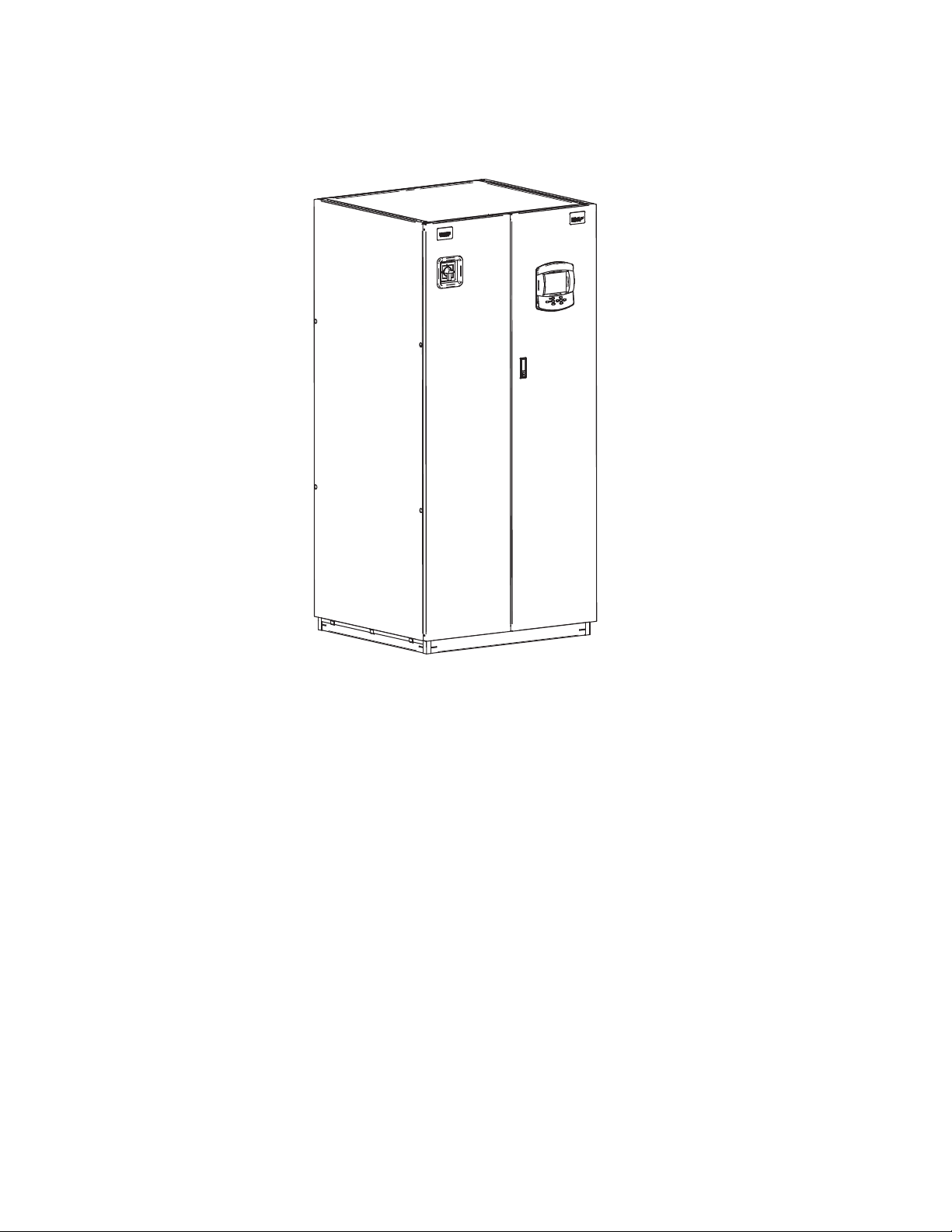
Liebert DCP
STANDARD FEATURES
HEAT EXCHANGER - Brazed plate design with interwoven circuiting constructed of stainless steel plates, copper brazed.
PUMPS - Centrifugal type.
STANDARD CONTROL PROCESSOR -
The standard control system is microprocessor-based with an external LCD numerical display to allow
observation of specified settable functions. Normal operating conditions are indicated on the LCD display panel,
which is
of the specified factory preset conditions are exceeded.
CABINET AND FRAME -
Custom powder painted steel panels. A hinged control access panel opens to a second front panel, which is a
protected enclosure for all high voltage components. Frame is constructed of 14 gauge heli-arc welded tubular steel
and painted us
mounted to the unit. The control system also monitors unit operation and activates an alarm when any
ing an auto-deposition coating system.
Page 1/5
DPN002400
REV DATE 11/11
REV 0
Page 2
Liebert DCP
Liebert DCP
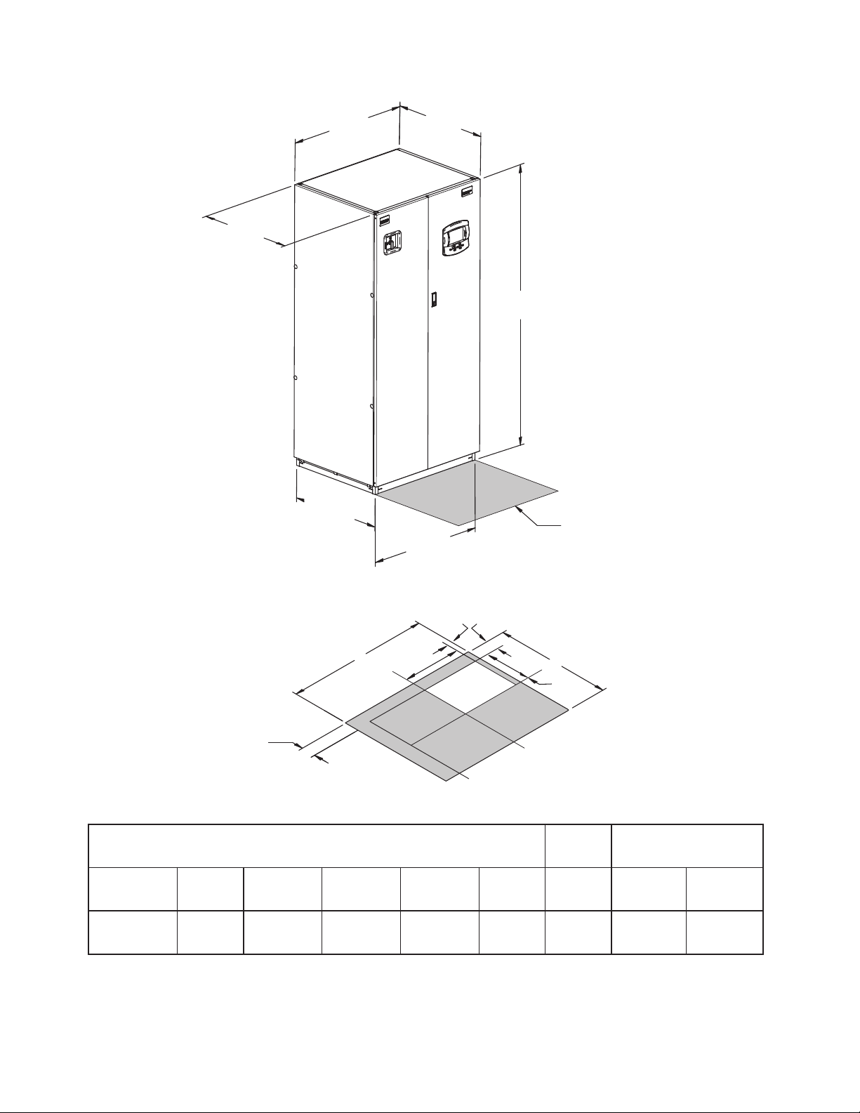
C
Side Panel
A
D
Unit Base
Overall
B
E
Unit Base
Overall
F
Height of Unit
The shaded area indicates a recommended
clearance of 36" (914mm) be provided for
component access.
Unit Dimensional Data
1"
25mm1"25mm
22. 1/2 "
572mm
F
Cut Out
1"
25mm
Floor Cutout Dimensions
DIMENSIONAL DATA inches (mm)
MODEL
50/60 HZ
DCP200
A
38 (965) 34 (864) 33 1/8(841) 34 (864) 37 (940) 78 (1981) 1020 (463) 1083 (491)
* Dimension Does Not Include the Bezel of the Disconnect Switch.
** Represent Dimensions of Drip Tray.
B*
C
D**
E**
D
14"
355mm
F
SHIPPED WEIGHT
lbs (kg)
DOM.
EXPORT
Page 2/5
PAGE 2/6
DPN002400
REV DATE 05/11
REV DATE 11/11
REV 0
REV 0
Page 3

Liebert DCP
Liebert DCP
Bottom View
Drip Tray Dimensions
34”
7.2”
3.1”
BCW OUT
SECONDARY
IN
37”
BCW IN
SECONDARY
OUT
19.5”
3.9”
3.8”
6.5”
Unit Piping Outlet Connection Sizes, inches, Od Cu
MODEL
50/60 HZ
A B C D
Pipe Connection Point
Page 3/5
PAGE 4/6
DPN002400
DCP200
2-5/8 2-5/8 2-5/8 2-5/8
REV DATE 05/11
REV 0
REV DATE 11/11
REV 0
Page 4

Three phase electric service
not provided by Liebert
Factory installed unit
disconnect switch
Field supplied disconnect switch may
not be required, check local codes.
Liebert DCP
Liebert DCP
Monitoring panel
Three phase electric service
not provided by Liebert
THREE PHASE CONNECTION
Electric service connection terminals
EARTH GROUND LUG
Connection terminal for
field supplied earth
grounding wire.
Factory installed disconnect switch
Factory wired to components
on electric panel
ELECTRIC CONDUIT KNOCKOUTS
On top of electric box. Knockout size
2 in (51 mm)
CANBUS ISOLATOR
ALARM AND WARNING OUTPUT RELAYS
Field supplied 24V Class 2 wire for
special alarms.
(Not to exceed 1.0A @ 24v each.)
REMOTE UNIT SHUTDOWN
Replace existing jumper between terminals
37 & 38 with normally closed switch having
a minimum 50VA rating. Use field supplied
24V Class 2 wire.
SITE MONITORING CONNECTION
Terminals 77 (-) and 78 (+) are for
connection of a 2 wire, twisted pair,
communication cable (available from
Liebert or others) for optional Sitescan.
(see user's manual).
INTELLISLOTS
Two Liebert Intellislots for optional
60HZ COMPONETS SHOWN
NOTE: Refer to specification sheet for full load amp. and wire size amp. ratings.
OCWEB-LBDS or OC485-LBDS card.
®
®
PAGE 5/6
Page 4/5
DPN002400
REV DATE 05/11
REV 0
REV DATE 11/11
REV 0
Page 5

Liebert DCP
Liebert DCP
Liebert DCP Extra Low Voltage field connection points
TO REMOTE T/H SENSOR A
P67
DO NOT
USE
TO P64 ON ICOM CONTROL BOARD
RED ETHERNET CABLE
TO REMOTE T/H SENSOR B
TO OPTIONAL
EXTERNAL
CONNECTIONS
P67P66
P64
UNIT DISPLAY (REAR VIEW)
FACTORY WIRED
TEMPERATURE SENSOR.
TO P66 ON ICOM CONTROL BOARD
TERMINATION PLUG
COMMON WARNING OUTPUT
FOR CONTACTS INDICATING AN
ALARM CONDITION.
(MAX) 1.0AMP @ 24V
K11
K11COM
K11NO
TO REMOTE ALARM
CIRCUIT BY OTHERS
INPUT: REMOTE ALARM DEVICE
FOR INDICATION OF ALARM, WIRE
N.O. CONTACTS FROM REMOTE
ALARM DEVICE AS SHOWN.
24 50
N.O. CONTACT BY OTHERS
INPUT: CONDENSATION
DETECTION
ALARM WHEN CLOSED.
N.O. CONTACTS REQUIRED
INPUT: FAN BREAKER STATUS
1
K11
K11NC
5124
NOTES:
1. CONTROL WIRING MUST BE CLASS 2 AND INSTALLED IN
ACCORDANCE WITH THE NATIONAL ELECTRICAL CODE (NEC).
2. REQUIRES SHIELDED CABLE.
ALARM WHEN CLOSED.
5424
N.O. CONTACTS REQUIRED
COMMON ALARM OUTPUT
FOR CONTACTS INDICATING AN
ALARM CONDITION.
(MAX) 1.0AMP @ 24V
K3
K3
K3COM
3837
78
(+)
R or W
K3NC
K3NO
TO REMOTE ALARM
1
2
CIRCUIT BY OTHERS
INPUT: REMOTE SHUTDOWN
FOR SHUTDOWN OF CONTROL
CIRCUIT, REMOVE JUMPER
BETWEEN TERMINALS 37 & 38
AND REPLACE WITH N.C. CONTACT
N.C. CONTACTS BY OTHERS
LIEBERT SITE MONITOR
FOR DIGITAL COMMUNICATIONS
WITH LIEBERT SITE MONITORS
ONLY. CONNECT 2 WIRE TWISTED
PAIR TO 77 & 78. ALSO SEE SITE
MONITOR INSTALLATION MANUAL.
77
(-)
BK
PAGE 6/6
Page 5/5
DPN002400
REV DATE 05/11
REV 0
REV DATE 11/11
REV 0
 Loading...