

Page 1

Precision Cooling
For Business-Critical Continuity
™
User Manual
Liebert® DM 16kW Air Conditioner
Page 2

Liebert_DM 16kW Air Conditioner User Manual
Liebert_DM 16kW Air Conditioner
User Manual
Version
V1.0
Revision date
March 5, 2013
BOM
31012820
Emerson Network Power provides customers with technical support. Users may contact the nearest
Emerson local sales office or service center.
Copyright © 2013 by Emerson Network Power Co., Ltd.
All rights reserved. The contents in this document are subject to change without notice.
Emerson Network Power Co., Ltd.
Address: No.1 Kefa Rd., Science & Industry Park, Nanshan District 518057, Shenzhen China
Homepage: www.emersonnetworkpower.com.cn
E-mail: support@emersonnetwork.com.cn
Page 3

Page 4

Liebert_DM 16kW Air Conditioner User Manual
Contents
Chapter 1 Overview ............................................................................................................................................................ 1
1.1 Model Description ................................................................................................................................................. 1
1.2 Product Introduction .............................................................................................................................................. 1
1.3 Main Components ................................................................................................................................................. 1
1.3.1 Indoor Unit ................................................................................................................................................. 1
1.3.2 Outdoor Unit .............................................................................................................................................. 2
1.3.3 Controlling System .................................................................................................................................... 2
1.3.4 Controller ................................................................................................................................................... 2
1.4 Environment Requirements .................................................................................................................................. 3
1.4.1 Operation Environment .............................................................................................................................. 3
1.4.2 Storage Environment ................................................................................................................................. 3
Chapter 2 Mechanical Installation ....................................................................................................................................... 4
2.1 Transportation, Unpacking And Inspection ........................................................................................................... 4
2.1.1 Transportation And Movement .................................................................................................................. 4
2.1.2 Unpacking .................................................................................................................................................. 4
2.1.3 Inspection .................................................................................................................................................. 5
2.2 Installation Notes .................................................................................................................................................. 5
2.3 System Installation Arrangement .......................................................................................................................... 6
2.3.1 General Arrangement ................................................................................................................................ 6
2.3.2 System Installation Sketch Map ................................................................................................................. 6
2.3.3 Mechanical Paremeters ............................................................................................................................. 7
2.4 Installing Indoor Unit ............................................................................................................................................. 9
2.4.1 Preparing Equipment room ........................................................................................................................ 9
2.4.2 Installation Space ...................................................................................................................................... 9
2.4.3 Requirement Of Maintenance Space ....................................................................................................... 10
2.4.4 Installation Procedures ............................................................................................................................ 11
2.5 Installing Outdoor Unit ........................................................................................................................................ 11
2.5.1 Installation Notes ................................................................................................................................ ..... 11
2.5.2 Space Requirements ............................................................................................................................... 12
2.5.3 Mounting base dimension ........................................................................................................................ 12
2.6 Piping .................................................................................................................................................................. 14
2.6.1 General .................................................................................................................................................... 14
2.6.2 Charging refrigerant and adding refrigerant oil ........................................................................................ 17
2.7 Base/Side Panel Cutout Locations ...................................................................................................................... 17
2.8 Removing Transport Fastener And Vibration Absorber ...................................................................................... 19
2.9 Component Adjustment ...................................................................................................................................... 22
2.10 Installation Inspection ....................................................................................................................................... 22
Chapter 3 Electrical Installation ......................................................................................................................................... 23
3.1 Work Introduction And Notes .............................................................................................................................. 23
3.2 Wiring Of Indoor Unit .......................................................................................................................................... 23
3.2.1 Locating Electrical Interface Of Indoor Unit ............................................................................................. 23
Page 5

3.2.2 Connecting Power Cable Of Indoor Unit .................................................................................................. 23
3.2.3 Connecting Control Cables ...................................................................................................................... 24
3.2.4 Connecting Extension Component Solenoid Valve (For Site Installation)................................................ 25
3.3 Wiring Of Outdoor Unit ........................................................................................................................................ 26
3.3.1 Connecting Power Cables For Outdoor Unit ............................................................................................ 26
3.3.2 Connecting Control Signal Cables Of Outdoor Unit ................................................................................. 26
3.3.3 Installation Inspection .............................................................................................................................. 27
3.3.4 HMI .......................................................................................................................................................... 28
3.3.5 Operation Description Of HMI .................................................................................................................. 29
Chapter 4 System Start-Up And Commissioning .............................................................................................................. 32
4.1 Location Of MCBs ............................................................................................................................................... 32
4.2 Power-on Commissioning ................................................................................................................................... 32
4.2.1 Preparation Before Commissioning ......................................................................................................... 32
4.2.2 Commissioning Procedures ..................................................................................................................... 33
4.2.3 Commissioning Complete Inspection....................................................................................................... 34
Chapter 5 Precision Air Conditioner Controller .................................................................................................................. 35
5.1 Appearance ........................................................................................................................................................ 35
5.2 Control Button ..................................................................................................................................................... 35
5.2.1 Function Description ................................................................................................................................ 35
5.2.2 Operation Example .................................................................................................................................. 35
5.3 Indicator ................................................................................................ .............................................................. 36
5.4 Control Interface ................................................................................................................................................. 36
5.4.1 OFF Interface .......................................................................................................................................... 36
5.4.2 MAIN Interface ......................................................................................................................................... 37
5.4.3 Password Interface .................................................................................................................................. 38
5.5 Menu Structure ................................................................................................................................................... 38
5.5.1 Guide On Finding Menus ......................................................................................................................... 38
5.5.2 Main Menu ............................................................................................................................................... 38
5.5.3 Alarm Menu ............................................................................................................................................. 39
5.5.4 Set Point Control ..................................................................................................................................... 41
5.5.5 System Status ......................................................................................................................................... 42
5.5.6 System Menu ........................................................................................................................................... 43
5.5.7 Set Time/Date .......................................................................................................................................... 46
5.5.8 Graph Menu ............................................................................................................................................. 47
5.5.9 Run Hours ............................................................................................................................................... 47
5.5.10 On/Off Record ....................................................................................................................................... 48
5.5.11 Team Work ............................................................................................................................................ 48
5.6 Help Menu .......................................................................................................................................................... 49
Chapter 6 System O&M .................................................................................................................................................... 50
6.1 Operation and maintenance of indoor unit ................................................................................................ .......... 50
6.1.1 Self-diagnosing Functions ....................................................................................................................... 50
6.1.2 Electric Control Part ................................................................................................................................. 50
6.1.3 Dust Filter ................................................................................................................................................ 51
6.1.4 Fan Kit ..................................................................................................................................................... 52
Page 6

Liebert_DM 16kW Air Conditioner User Manual
6.1.5 Infrared Humidifier ................................................................................................................................... 52
6.1.6 Electric Reheat ........................................................................................................................................ 54
6.1.7 Cooling System ....................................................................................................................................... 54
6.1.8 Replacing The Compressor ..................................................................................................................... 56
6.2 Operation and maintenance of outdoor unit ........................................................................................................ 57
6.2.1 Maintenance ............................................................................................................................................ 57
6.2.2 Troubleshooting ....................................................................................................................................... 58
Chapter 7 Troubleshooting ................................................................................................................................................ 59
Appendix 1 SiteMonitor Software Introduction .................................................................................................................. 63
Appendix 2 Circuit Diagram of DME16 .............................................................................................................................. 64
Appendix 3 Circuit diagram of DMC16M2 ......................................................................................................................... 65
Appendix 4 Menu Structure ............................................................................................................................................... 66
Appendix 5 Alarm Control Menu Table.............................................................................................................................. 67
Appendix 6 Parameter Setting Table ................................................................................................................................ 68
Page 7

Page 8

Chapter 1 Overview 1
Liebert_DM 16kW Air Conditioner User Manual
Chapter 1 Overview
This chapter introduces the features, main parts, requirements on transportation and storage environment of the
Liebert_DM 16kW (DME16) air conditioner.
1.1 Model Description
The model description of Liebert_DM 16kW air conditioner is shown in Figure 1-1.
Figure 1-1 Model description
1.2 Product Introduction
Liebert_DM 16kW air conditioner is a medium-large sized precision environment control system, suitable to the
environment control of the equipment room or computer room. It aims to provide a sound operation environment for
precision equipment, such as sensitive equipment, industry processing equipment, communication equipment and
computers.
Liebert_DM 16kW air conditioner features high reliability, high sensible heat ratio and large airflow. It is configured with
an infrared humidifier adjustable to different water qualities, and is compatible with R407C refrigerant to meet the
requirement.
Liebert_DM 16kW air conditioner comprises indoor unit and outdoor unit. With the standard condenser unit, the
Liebert_DM 16kW air conditioner can reduce noise pollution to the minimum while meeting system cooling
requirement.
1.3 Main Components
1.3.1 Indoor Unit
The indoor unit of the Liebert_DM 16kW air conditioner includes compressor, evaporator, electric reheat, fan, controller,
infrared humidifier, thermal expansion valve, sight glass and drier-filter.
Compressor
The Copeland scroll compressor features low vibration, low noise and high reliability. The connection mode of
Rotalock makes the maintenance easier.
Evaporator
Finned tube evaporator with high heat dissipation efficiency is used. The distributor, with its model-specific design,
ensures that the refrigerant is distributed evenly in each loop, improving the evaporator efficiency to a great extent.
Thermal expansion valve
The external equalizer type thermal expansion valve collects temperature and pressure signals at the same time, so
that it can regulate the refrigerant flow more accurately.
DM E
16
U M H
2
Version
Power supply
: M -
three phase
/
50
Hz / 400 V E - indoor unit
; C -
outdoor unit
Liebert_DM
Cooling capacity class
:
16 - 16
kW
Air path
: U -
upflow
; F -
downflow
; D -
duct
C - cooling only
; O -
with heater
; H -
with heater and humidifier
Page 9

2 Chapter 1 Overview
DM Series 16kW Air Conditioner User Manual
Infrared humidifier
The infrared humidifier is designed with a simple structure, which is easy for teardown, cleaning and maintenance. It is
adjustable to a wide range of water qualities, with fast startup and high humidifying efficiency.
Fan
The system uses centrifugal fan with high efficiency and reliability, large airflow and long blowing distance. With the
belt transmission mechanism, it is easy for maintenance.
Electric reheat
The indoor unit adopts the PTC electric heater with a quick heating rate and even heat quantity.
Sight glass
The sight glass is the window for observing the system refrigerant recycle, mainly the moisture content of system.
When the moisture content is too high, the color will change from green to yellow.
Filter drier
The filter drier can effectively eliminate the moisture in system within a period of time, filtrate the impurities generated
during long-term system operation and ensure normal system operation.
1.3.2 Outdoor Unit
The outdoor unit DMC16M2 condenser is applicable to Liebert_DM 16kW air-cooled series.
The DMC16M2 condenser is the newly standard configuration outdoor unit of the Liebert_DM 16kW AC. It adopts
corrugated finned tube heat exchanger which features high heat dissipation efficiency, convenient cleaning and
maintenance. External rotor axial fan with unique ‘sickle’ shape metal fan leaf has the superior aerodynamic property.
The six and eight pole fan, with specially designed draught ring, makes the air flow noise through the fan leaf
significant reduction. The high performance three-phase motor that is customized for the base station power grid
environment can be applicable to the wide voltage range and has the higher reliability. The advanced fan speed
control system regulates the voltage output by detecting the condensing pressure of the system to control the outdoor
fan speed and make the system pressure and heat load adaptable. It makes sure that the AC unit can operate stably,
reliably and efficiently.
1.3.3 Controlling System
1.3.4 Controller
The micro-processing controller of Liebert_DM 16kW air conditioner uses the LCD screen with blue backlight and 240
× 128 pixels. The user interface operation is simple. The multi-level password protection can effectively prevent illegal
operation. The controller also features power failure auto-restoration and high / low voltage protection function. The
operation time of components is available through the menus. The expert-level fault diagnosis system can display the
current fault information automatically, facilitating the maintenance. The controller can store 200 records of historical
events. The panel of micro-processing controller is shown in Figure 1-2.
LCD screen
UP button
ENTER button
DOWN button
ON/OFF button
ESC button
Running indicator
Alarm indicator
Figure 1-2 The panel of micro-processing controller
Page 10
Chapter 1 Overview 3
Liebert_DM 16kW Air Conditioner User Manual
1.4 Environment Requirements
1.4.1 Operation Environment
See Table 1-1 for the details.
Table 1-1 Operation enviroment requirement
Item
Requirement
Environment temperature
Indoor: 0℃~40℃
Outdoor:
-15℃~+45℃
Protection level (outdoor unit)
IP55
Altitude
<1000m. Above that, derating is required
Operation voltage range
380V (-10% ~ +15%), 3N ~ 50Hz
1.4.2 Storage Environment
Table 1-2 Storage enviroment requirement
Item
Requirement
Storage environment
Indoor, no dust
Environment humidity
5%RH ~ 85%RH (non-condensing)
Environment
temperature
-40℃~+70℃
Storage time
Total transportation and storage time should not exceed 6 months. Otherwise, the performance needs
to be re-evaluated
Page 11

4 Chapter 2 Mechanical Installation
DM Series 16kW Air Conditioner User Manual
Chapter 2 Mechanical Installation
This chapter introduces the mechanical installation of the Liebert_DM 16kW air conditioner, which includes
transportation, installation arrangement and installation procedures.
2.1 Transportation, Unpacking And Inspection
2.1.1 Transportation And Movement
Railroad transportation and shipping are the recommended means of transportation. If truck transportation is
unavoidable, choose roads that are less bumpy in order to protect the equipment.
The Liebert_DM 16kW air conditioner is heavy (see Table 2-1 for the weight parameters). It is recommended to use
mechanical handbarrow such as electric forklift when unpacking and moving the equipment to the place most close to
the installation site. Insert the tines of the forklift below the pallet, as shown in Figure 2-1. Align the tines to the center
of gravity to prevent the unit from falling over.
Figure 2-1 Forklift removal
When moving the indoor unit, keep the obliquity within 75° ~ 105°, as shown in Figure 2-2.
105
75
Figure 2-2 The obliquity of indoor unit
2.1.2 Unpacking
Move the product to the place most close to the final installation site before unpacking the unit.
Follow the procedures below to unpack the unit:
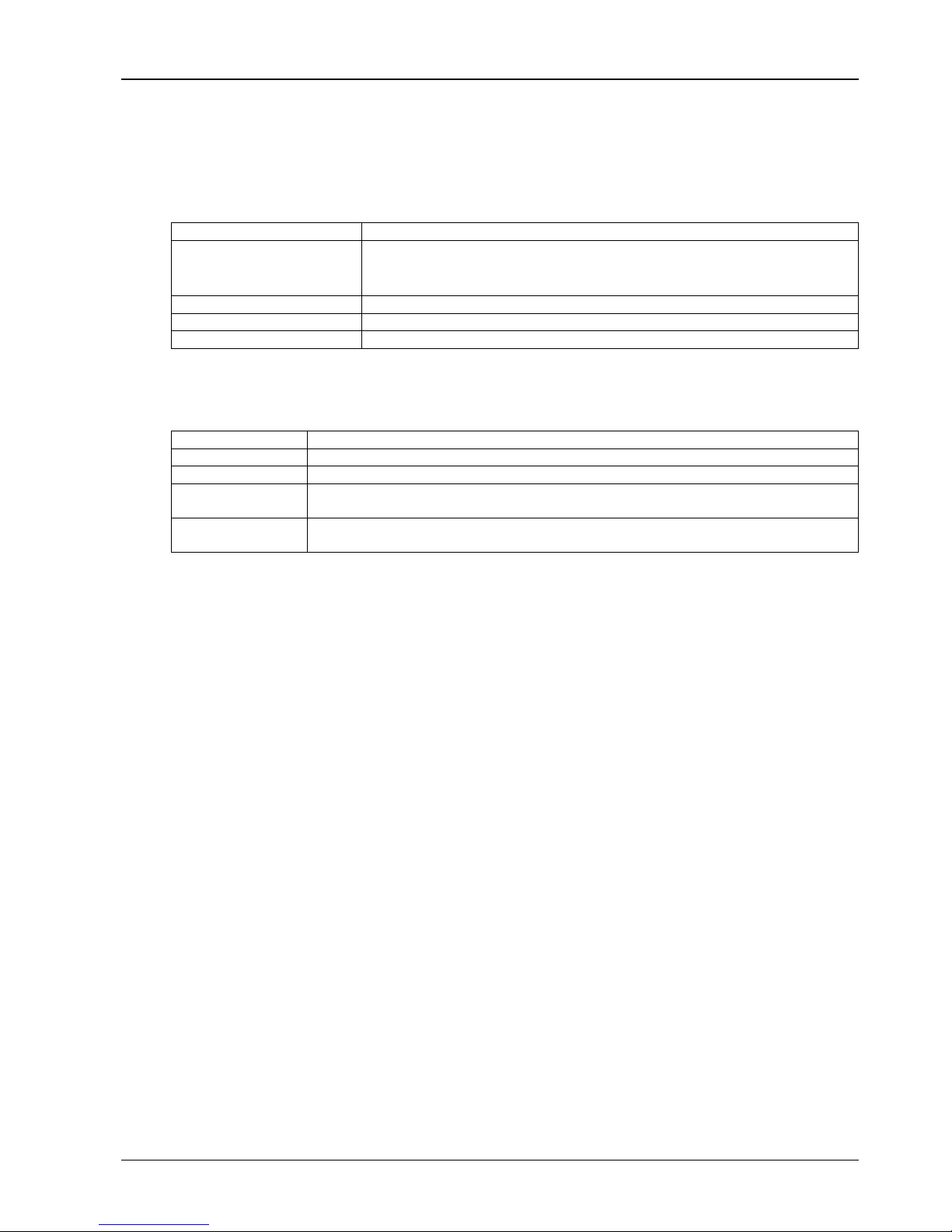
1. Removing the side boards and top cover
Liebert_DM 16kW air conditioner uses the international packaging. You can use a hammer or straight screwdriver to
straighten the hook, as shown in Figure 2-3.
Figure 2-3 Straighten the hook
Page 12
Chapter 2 Mechanical Installation 5
Liebert_DM 16kW Air Conditioner User Manual
At first, straighten all the hooks that fix side board I, and remove side board 1. Then straighten all the hooks that fix
side board 2, and remove side board 2. At last remove top cover 3, as shown in Figure 2-4.
Kg
1790 x 950 x 2020mm
1816 x 976 x 2175mm
1
2
1
2
3
Figure 2-4 Remove side boards and top cover
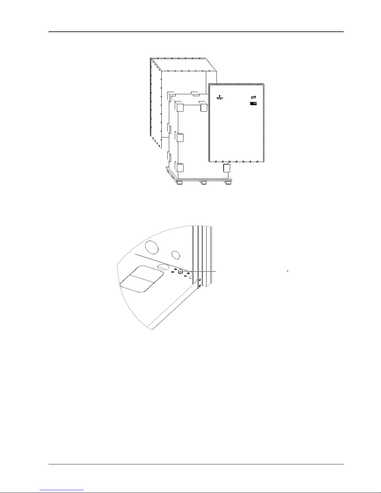
2. Removing the pallet
Liebert_DM 16kW air conditioner is fixed onto the pallet with M10 × 70 screws, as shown in Figure 2-5. You can use
M10 open-end spanner, ratchet spanner or sleeve to remove the screws.
Fixed screw on base pallet (M10 70)
Figure 2-5 Screws on pallet
2.1.3 Inspection
After receiving the product, you should check against the packing list. If any parts are found missing, distorted or
damaged, please report to the carrier immediately. If any covert defects are found, please report to the carrier and the
distributor.
2.2 Installation Notes
To realize the designed performance and maximum product life, the installation must be correct. This section should
be used in conjunction with local industry standards for mechanical and electrical installations.
Liebert_DM 16kW air conditioner is designed for split floor installation. The indoor unit must be installed on the floor of
the equipment room or computer room, and the outdoor unit can be installed outdoors or on the floor of other rooms.
Before installation, make sure that the installation environment meets the requirements (see 1.4 Environment
Requirements) and the building should be transformed to accommodate the construction work of piping, wiring and
ventilation ducts.
Page 13

6 Chapter 2 Mechanical Installation
DM Series 16kW Air Conditioner User Manual
Follow the design drawings strictly when installing the equipment, and reserve the space for maintenance. The
manufacturer’s engineering dimensions drawings can serve as a reference.
2.3 System Installation Arrangement
2.3.1 General Arrangement
The general arrangement of Liebert_DM 16kW air conditioner is shown in Figure 2-6.
Scroll compressor
Service valve
Suction line
Discharge line
Ball
valves
Sensing bulb
Evaporator coil
Dehum solenoid valve
Thermal expansion valve
Sight glass
Filter drier
Solenoid valve
High pressure switch
Charging port
Low pressure switch
Condenser coil
Check valve
Distributor
Traps(every 7.5m
of vertical lift)
#1 circuit only
Figure 2-6 General arrangement diagram of air-cooled series
Note
1. : Factory piping.
2. : Field piping (by others).
3. *: Components are not supplied by Emerson but are recommended for proper circuit operation and maintenance.
4. +: Components are required when the equivalent length exceeds 30m.
2.3.2 System Installation Sketch Map
The installation mode of air-cooled series unit is shown in Figure 2-7 and Figure 2-8.
Note
1. If the condenser is installed higher than the compressor, an external back bend should be fitted to the suction line and liquid
return line of the condenser, so as to prevent the liquid refrigerant from flowing back when the condenser stops.
2. The top end of the back bend must be installed higher than the highest copper pipe of the condenser.
Page 14

Chapter 2 Mechanical Installation 7
Liebert_DM 16kW Air Conditioner User Manual
Slope dicharge
Back bend (higher than the highest copper pipe of condenser
)
Liquid line
( do not expose liquid line to sun )
Trap
Heat insulation floor
Seal
Outdoor unit
Indoor unit
Floor
Condenser
Humidifier
The earth surface
Max.7
.
5
m
Max
.20m
water in
water out
Supporting bar
Figure 2-7 Condenser installed higher than compressor
Supporting bar
Slope dicharge
Heat insulation floor
Seal
Outdoor unit
Floor
Condenser water out
Humidifier water in
The earth surface
Max.5m
Slope liquid
Indoor unit
Figure 2-8 Compressor installed higher than condenser
2.3.3 Mechanical Paremeters
Indoor unit
The mechanical parameters of the indoor unit are shown in Figure 2-9.
Page 15

8 Chapter 2 Mechanical Installation
DM Series 16kW Air Conditioner User Manual
874
256
54
1970
853
50
400
874
1970
853
50
Figure 2-9 Mechanical parameters of the indoor unit
Plenum
You can select the air supply plenum with grids for the upflow system. The appearance of the plenum is shown in
Figure 2-10. The dimensions are listed in Table 2-1.
C
B
A
Figure 2-10 Appearance of the plenum
Table 2-1 Dimensions of plenum
A B C
867 853
400 (600,optional)
Note
If the height of the plenum selected for air conditioner unit exceeds 600mm, consult the factory for non-standard production..
Outdoor unit
The appearance of outdoor unit is shown in Figure 2-11.
The dimensions and mechanical parameters of outdoor unit are shown in Figure 2-12.
Page 16

Chapter 2 Mechanical Installation 9
Liebert_DM 16kW Air Conditioner User Manual
风机
电控盒(内有风
机转速控制器)
压力传感器
Fan
Electrical control box(there is a fan speed
controller inside)
Pressure sensor
Figure 2-11 Appearance of outdoor unit
1385
992
664
Figure 2-12 Dimensions and mechanical parameters of outdoor unit
2.4 Installing Indoor Unit
2.4.1 Preparing Equipment room
The requirements of equipment room are as follows:
1. Damp proof and heat preservation must be done to make sure that the system can operate normally.
2. The equipment room should have good heat insulation and sealed damp proof layer. The damp proof layer of the
ceiling and walls must use polyethylene film, and the coating of the concrete wall and the floor must be damp proof.
3. Prevent the outdoor air from entering the equipment room, because the outdoor air that enters the equipment room
may increase the load of heating, cooling, humidifying and dehumidification of the system. It is recommended that the
inhalation of outdoor air be kept below 5% of the total indoor airflow.
4. All the doors and windows should be closed and the seams should be as narrow as possible.
2.4.2 Installation Space
Note
Liebert_DM 16kW air conditioner system will generate condensed water, and water leakage may damage the precision
equipment nearby. So do not install the system in the vicinity of any precision equipment, and the installation site must provide
draining pipes.
1. To ensure normal operation, the installation space for the indoor unit shall be capacious enough.
2. Too small space for the indoor unit will baffle the airflow, shorten the cooling cycle; the air supply and air exhaust
may mix, and the decibel may rise.
3. Do not place the indoor unit in a concave or at the end of a strip area.
4. Do not huddle multiple indoor units, lest there should be mixed airflow, unbalanced load and competitive operation.
Page 17
10 Chapter 2 Mechanical Installation
DM Series 16kW Air Conditioner User Manual
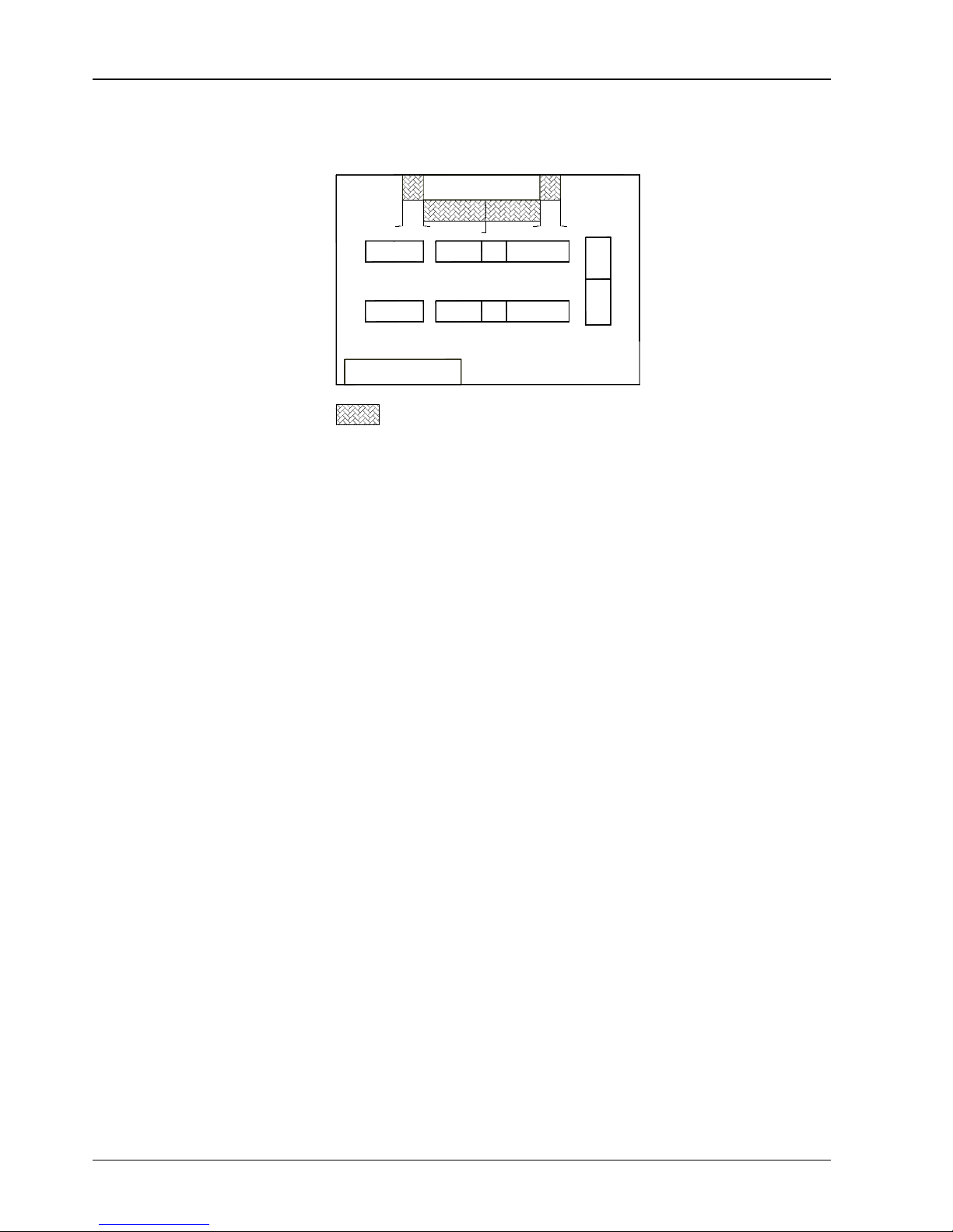
5. For the convenience of daily maintenance, do not install other equipment (such as smoke detector) above the
cabinet.
Figure 2-13 shows the installation place of the indoor unit.
Good place
Unit
Unit
Note:
The reserved maintenance space while installing
600600 600
Bad place
Figure 2-13 Installation place of indoor unit (unit: mm)
2.4.3 Requirement Of Maintenance Space
Leave more than 600mm of maintenance space in the front and two sides of the indoor unit, as shown in Figure 2-13.
Page 18
Chapter 2 Mechanical Installation 11
Liebert_DM 16kW Air Conditioner User Manual
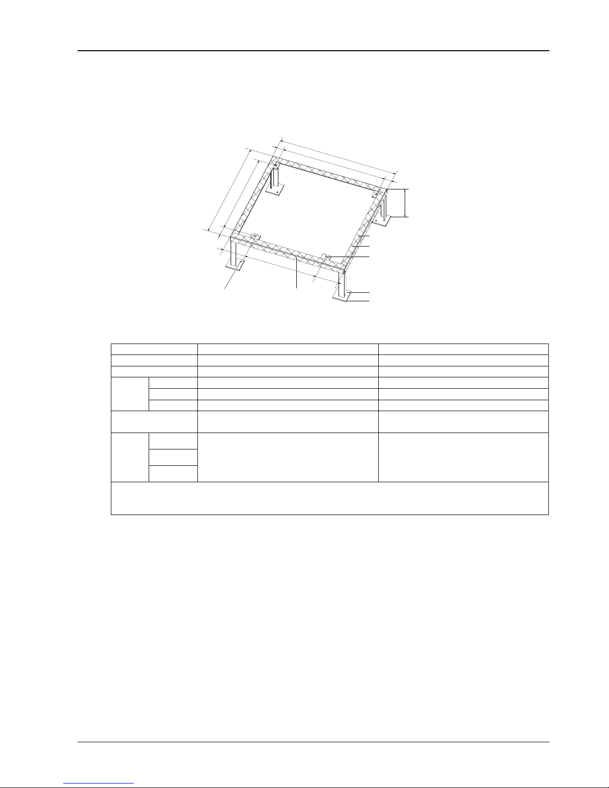
2.4.4 Installation Procedures
The installation procedures of indoor unit are as follows:
1. Make the mounting base according to the dimensions in Figure 2-14 and the requirements in Table 2-2. You can
make it by yourself or contact Emerson Network Power Co., Ltd. for non-standard production.
161.5
530
161.5
67
680.5
820
760
853
H
46.5
Steel plate
Angle steel
Installation hole
for expansion bolt
4-Ф 14
cabinet installation hole
Rubber cushion(top)
Front side of cabinet
Rubber cushion (bottom)
Rear side of
cabinet
Rubber cushion (lateral)
46.5
Figure 2-14 Mounting base of one bay series
Table 2-2 Specifications of indoor unit mounting base
Item
Specification
Remark
Steel plate
100mm × 100mm × (5 ~ 6.5)mm
-
Angle steel
40mm × 40mm × 3mm
-
Rubber
cushion
Top
Thickness: 3mm ~ 5mm
-
Lateral
Thickness: 2mm ~ 3mm
-
Botton
Thickness: 10mm ~ 12mm
-
Installation hole for
expansion hole
-
Install the holes according to your requirements
H
One bay
H = 200mm (upflow unit)
H = 300mm (downflow unit, according to the floor
height)
1. The upflow unit do not need the flow deflector
2. The H dimension is only a reference. It should
be determined accroding to your actual
requirements during making the mounting base
Two bay
Three bay
Note:
The external side boards of the unit cannot bear weight. Take this into consideration while selecting angle steel and fixing holes
As the value of H exceeds 450mm, please strengthen the mounting base or contact Emerson Network Power Co., Ltd.
2. Lay a layer of rubber cushion on the top, lateral of mounting base and on the bottom of the steel plate respectively.
See Figure 2-18, Figure 2-19 and Figure 2-20 for their positions and see Table 2-3 for the thickness.
3. Identify the installation position. Fix the mounting base onto the mounting base according to the site conditions and
your requirement.
4. Fix the AC unit onto the mounting base with nuts, spring washers, flat washers and bolts.
2.5 Installing Outdoor Unit
2.5.1 Installation Notes
The installation notes of the condenser are as follows:
1. To ensure the heat dissipation capacity, install the condenser in the place with smooth air flow. Do not install it where
the coil of the condenser may be obstructed by dust and snow. Ensure that there is no steam or waste heat around.
2. If possible, the horizontal installation is recommended to reduce the noise.
3. The condenser should be installed as far away as possible from residential areas (≥15m).
Page 19
12 Chapter 2 Mechanical Installation
DM Series 16kW Air Conditioner User Manual
4. Be careful not to damage the waterproof layer and observe the local rules and regulations when the condenser is
installed on the roof of building.
5. Position the condenser higher than the indoor unit to ensure normal oil return.
6. Follow the installation arrows on the condenser for the installation direction.
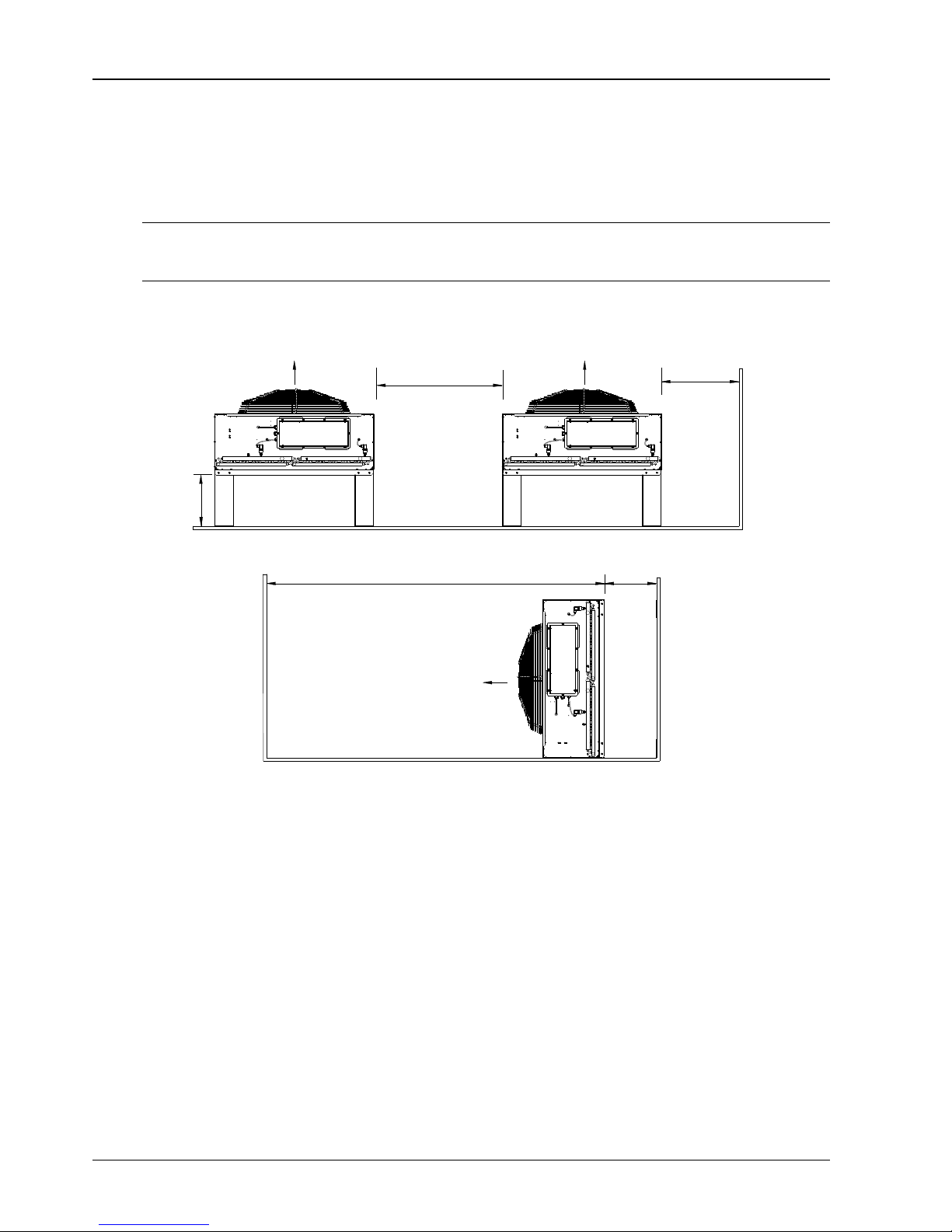
2.5.2 Space Requirements
Note
1. A 4000mm clearance is required around the condenser air outlet.
2. The 600mm service spaces are required on the four sides of the condenser.
The condenser needs sufficient installation and service space around the installation place. The detailed space
requirements are shown in Figure 2-15 and Figure 2-16.
600
1200
450
Air flowAir flow
Figure 2-15 Horizontal installation space requirement (unit: mm)
600
4000
Air flow
Figure 2-16 Vertical installation space requirement (unit: mm)
2.5.3 Mounting base dimension
Mounting base for horizontal installation
The mounting base for horizontal installation is shown in Figure 2-17 and the mounting base dimensions of each
model are listed in Table 2-3.
Page 20

Chapter 2 Mechanical Installation 13
Liebert_DM 16kW Air Conditioner User Manual
D
D
L'
D
H'
D
Amplified part figure
D
D
Installation holes
(8 holes in total )
Bottom view
455
455
148 B
148
C
Front view Side view
Figure 2-17 Mounting base dimensions for horizontal installation (unit: mm)
Table 2-3 Mounting base dimensions for horizontal installation (unit: mm)
Model
Dimension
(L' × H' × D)
B
C
DMC16M2
1126 × 837 × 53
980
691
Note
The installation holes are long and flat holes. It is recommended to use M10 × 20 bolts to fix the mounting base.
Mounting base for vertical installation
The mounting base for vertical installation is shown in Figure 2-18, and the dimensions of each model are listed in
Table 2-4.
250
102
452
490
a
2020
Installation
hole (4 pcs)
Amplified
part figure
Figure 2-18 Mounting base dimensions for vertical installation (top view) (unit: mm)
Table 2-4 Mounting base dimensions for vertical installation (unit: mm)
Model
Dimension ‘a’
DMC16M2
1280
Note
1. The installation holes are long and flat holes. It is recommended to use M10 × 20 bolts to fix the mounting base.
2. When one condenser needs to be installed on another one, the upper condenser must be installed on a rack and cushion pads
should be used between the condenser and the rack for damping. It is prohibited to stack two condensers and bolt them together
directly.
Page 21

14 Chapter 2 Mechanical Installation
DM Series 16kW Air Conditioner User Manual
2.6 Piping
All joints of the cooling pipes must be silver brazed. Standard industry procedures must be followed in selecting, laying,
and fixing the pipes, and in vacuuming the system and charging refrigerant. Take pipeline pressure drop, oil return to
the compressor and minimization of noise and vibration into consideration during the design and construction.
2.6.1 General
The recommended pipe sizes are ‘equivalent lengths’ (see Table 2-5 for equivalent lengths of partial components),
which has included the resistance brought about by bends. You should confirm that the sizes are appropriate for the
site conditions.
1. If the one-way equivalent length exceeds 30m, or if the vertical difference between indoor unit and outdoor unit
exceeds the values in Table 2-5, consult the factory before installation for confirmation whether extended components
are needed.
Table 2-5 Vertical difference between indoor unit and outdoor unit
Relative position
Value
Indoor unti lower than outdoor unit
Max.: +20m
Outdoor unit lower than indoor unit
Max.: -5m
2. The pipe sizes recommended in Table 2-6 are ‘equivalent lengths’, which has included the resistance brought about
by bends and valves. You should confirm that the sizes are appropriate for the site conditions.
Table 2-6 Equivalent lengths of partial components
Outer Diameter (OD) of
liquid pipe (inch)
Equivalent length (m)
90°bend
45°bend
T type three way
3/8
0.21
0.10
0.76
1/2
0.24
0.12
0.76
5/8
0.27
0.15
0.76
3/4
0.3
0.18
0.76
7/8
0.44
0.24
1.1
1-1/8
0.56
0.3
1.4
Note
A trap is required for every 7.5m of vertical lift. Please consult the factory for detailed information.
Connecting pipes
The pipes to connect include:
1. Cooling water drain-pipe of indoor unit
2. Water supply pipe of infrared humidifier
3. Connecting copper pipe (exhaust pipe and liquid return pipe) between indoor unit and outdoor unit
4. Installing extension subassembly (optional)
Connecting cooling water drain-pipe of indoor unit
The cooling water of infrared humidifier and evaporator is converged by the cross connector and drains through the
draining pipe, as shown in Figure 2-19. The OD of the pipe is 25mm. If the draining pipe is used by three or more units,
the minimal OD of the pipe should be 40mm.
Note
Because the humidifier contains boiling water, the plastic pipe must be rated higher than 90℃.
Page 22

Chapter 2 Mechanical Installation 15
Liebert_DM 16kW Air Conditioner User Manual
Water supply pipe of
infrared humidifier
Connector of condensation
water drain pipe
To condensation water
pan of evaporator
To infrared humidifier
water pan
Cross connector
Hose clamp
To condensation water
pan of evaporator
To the condensation
water drain pipe
Figure 2-19 Connection of drain pipe
Note
1. A Φ25 hose clamp is delivered as an accessory to connect the draining pipe.
2. When connecting the draining pipe, make sure that the U bend is installed vertically and the ‘U’ shape is not distorted, so as to
ensure that the cooling water can be drained immediately and effectively.
Connecting water supply pipe of infrared humidifier
The water pipes should be connected for the infrared humidifier. To facilitate maintenance, a strainer / non-return
isolation valve is fitted to the supply water pipe. The infrared humidifier water supply pipe reserves a copper pipe (OD:
6.35mm, see Figure 2-20) with a 1/4” copper nut at the end of the pipe. Take out of the 1/4” × 1/2” screw-thread copper
connector from the accessory bag and screw the connector onto the copper pipe. You can also select other connection
modes according to the site condition. Make sure the connection is well sealed to prevent leakage. The pipe pressure
is 100kPa ~ 700kPa.
Where the main pressure may rise above 700kPa, a pressure reducer should be fitted. Where the pressure falls below
100kPa, a water tank and pump system should be used.
Note
Main water supply connections must be made in accordance with local laws and regulations.
Water supply solenoid valve
Water level sensor
Water supply pipe
Ceramic terminal socket
Over-temperature
protection relay
Water pan (removable)
OD6.35mm
Over-temperature protection
switch (under the pan)
Water pan fixing screw
Water level regulator
Stainless steel bolt
Over-temperature
protection switch
Water outlet
A direction
Wiring cover plate
A direction
Water supply pipe
Figure 2-20 Infrared humidifier
Page 23

16 Chapter 2 Mechanical Installation
DM Series 16kW Air Conditioner User Manual
Connecting copper pipe (exhaust pipe and liquid return pipe) between indoor unit and outdoor unit
The indoor unit and outdoor unit are connected through welded copper pipes. The connection of discharge pipe / liquid
pipe of indoor unit is shown in Figure 2-21. Note that the ball valve must be wrapped with a wet cloth before welding. In
addition, many notes and instruction labels are pasted onto the base board and side board close to the ball valve. Do
not have them burned during the welding operation.
Note
The exposure time of system pipes do not exceed 15min. Otherwise, it will lead to the POE refrigeration oil moisture effect the
life of the key components and the system operation stability.
Horizontal sections of discharge pipes should be sloped downward from the compressor, with a slope of at least 1:200
(5mm down for each 1m run). Discharge pipes should be heat insulated where they are routed in the conditioned
space (including under a raised floor).
The liquid pressure drop should not exceed 40kPa (5psi ~6psi), provided that there is no loss of refrigeration. The
liquid line pressure drop is the sum of liquid flow resistance from the tubing and fitting (including the drier), plus the
loss of head pressure due to elevation above the condenser. If the liquid temperature is 38℃, the static pressure loss
is 11kPa (1.6 psi) per meter of lift.
Ball valve(liquid line)
Ball valve(discherge line)
Figure 2-21 Connection of discharge pipe / liquid return pipe
Considering the effect of the pipe OD to the system pressure drop, the pipe OD of indoor unit and outdoor unit should
be determined according to the specifications listed Table 2-7.
Table 2-7 Recommended pipe sizes
Eq.Lgth D L
10m
22
13
20m
22
13
30m
22
13
40m*
22
13
50m*
22
13
60m*
22
16
Note
1. Extension subassembly should be added to the “Eq.Lgth” marked with *.
2. D: discharge line, L: liquid line.
3. Consult factory if the line length exceeds 60m.
Installing the extension subassembly (be applicable to site installation)
When the equivalent length of pipe exceeds 30m, the extension subassembly should be installed. It is recommended
to install the solenoid valve of the extension subassembly to the outside project pipe of the ball valve on the liquid pipe,
or the outer side (or on the bottom) of the unit.
So, during installing the solenoid valve, you need not to cut the indoor unit pipes. After the whole system is installed,
you can open the ball valve to keep pressure and carry out vacuum operation, avoiding the moisture absorption of the
compressor refrigeration oil and ensuring the operation safety and life of the compressor. For installation valve of the
check valve, refer to Figure 2-6.
Page 24

Chapter 2 Mechanical Installation 17
Liebert_DM 16kW Air Conditioner User Manual
2.6.2 Charging refrigerant and adding refrigerant oil
1. Charging with refrigerant
The Liebert_DM 16kW air conditioner had been charged with 2bar nitrogen to keep pressure at the factory. In project
installation, see the unit nameplate for the initial charging capacity of Liebert_DM 16kW air conditioner.
If the connecting pipe between the indoor unit and the outdoor unit is longer than 10m, add refrigerant to the system in
order to ensure normal system operation.
The amount of the refrigerant is calculated through the following formula:
Refrigerant amount (kg) = unit length liquid pipe refrigerant amount (kg/m) × length of extended pipe (m)
See Table 2-8 for the unit length liquid pipe refrigerant amount.
Length of extended pipe (m) = Total length of liquid pipe (m) - 10m
Table 2-8 Unit length liquid pipe refrigerant amount of pipes with different ODs
Pipe OD (mm)
Unit length liquid pipe refrigerant
amount (kg/m)
Pipe OD (mm)
Unit length liquid pipe refrigerant
amount (kg/m)
9.52
0.060
19
0.261
12.7
0.112
22
0.362
16
0.181
28.6
0.618
2. Adding POE refrigerant oil
The added refrigerant will dilute the POE refrigerant oil in the system, undermining the lubricating and cooling effects
of the POE refrigerant oil. Therefore more POE refrigerant oil should be added. See the formula below:
Amount of refrigerant oil to be added (ml) = amount of added refrigerant (kg) × 22.6
2.7 Base/Side Panel Cutout Locations
Base cutout locations
Figure 2-22 and Figure 2-23 show the base figures with the side panel removed, and the distance between the dashed
lines and the rear panels is 25 mm, where is the mounting place of inner side panel.
530
160
72.5
80
200
45
760
7245109
798
680.5
161
140
D
IRWI
F
F
F
F
P
WO
/LL
WI
/DL
K K
4-Φ 13
25
25
50
Knock-out
Knock-out
2-Φ 35
Knock-out
2-Φ 64
Knock-out
2-Φ 40
IRWI: Infrared humidifier water in
D: Drain
P: Power cable entry (Φ30)
F: Unit set screw
K: Knock-out
LL/DL: Liquid line / discharge line (air-cooled models)
WI/WO: Condenser water inlet and outlet (water-cooled
models)
Figure 2-22 Base cutout location of upflow models
Page 25

18 Chapter 2 Mechanical Installation
DM Series 16kW Air Conditioner User Manual
160
530
680.5
72.5
45
143
80
45
140
103.5
75
45
81
72.5
70
kk
D
IRWI
WO/LL
WI
/DL
P
F
F
50
4-Φ 13
Knock-out
Fan aperture
2-Φ 35
Knock-out
2-Φ 64
Knock-out
2-Φ 40
P: Power cable entry
D: Drain
IRWI: Infrared humidifier water in
K: Knock-out (250×120)
F: Unit set screw
LL/DL: Liquid line / discharge line (air-cooled models)
WI/WO: Condenser water inlet and outlet (water-cooled models)
Figure 2-23 Base cutout location of downflow models
Side panel cotout locations
The knock-out dimensions of side panels are shown in Figure 2-24 and Figure 2-25.
95
20
59
50.8
53
45
49.2
4-Ф 64敲落孔
2-Ф 25敲落孔
4-Φ64 knock-out
2-Φ25 knock-out
Figure 2-24 Left side panel
79
.
8
160
.
2
50
145
4-Ф35
knock-out
Figure 2-25 Right side panel
Page 26

Chapter 2 Mechanical Installation 19
Liebert_DM 16kW Air Conditioner User Manual
2.8 Removing Transport Fastener And Vibration Absorber
In order to protect partial components from damaging and distorting due to bumping, impact and resonation, fasteners
and vibration absorbers are mounted at certain locations before delivery. Remove the fasteners and vibration
absorbers before installation and commissioning.
Removing transport fixing plate from the compressor
To reduce the compressor operation vibration and noise, the vibration absorbing cushions are added to the
compressor base. However, such device cannot best restrain the equipment vibration during the transportation,
resulting in loosened connections and wearing of certain parts. To counteract such effect, three L shaped plates are
added to the compressor base during the transportation, as shown in Figure 2-26.
Fixing plates
Figure 2-26 Compressor fixing plates
After the installation and before the commissioning, remove the three fixing plates, then restore the washers and bolts.
The fastening torque of the bolts is (12 ± 1)N.m.
Removing transport fastener of fan compoents
1. Upflow unit
The motor base of the fan is designed with a semi-free self-tension structure to minimize the fan operation noise and
prolong the belt life. During the transportation, to protect the semi-free structure from failing or collapsing due to
resonation, the upflow unit is especially fastened with bolts (left and right symmetrical, two at either side), as shown in
Figure 2-27. You should cut the binding string on the belt and remove the four fixing bolts before the power-on
operation, otherwise the fan could be damaged and even cause personal injury. Removing the bolts requires the
collaboration of two persons, with one holding the motor and the other removing the bolts.
Note
After you open the front door of unit, you will see a warning label concerning bolt removal on the sealing panel of the fan. Do
remove the bolts by following the preceding instructions.
Transportation bolts
(two on either side)
Binding string
Figure 2-27 Fixed bolts and trap wrench of transport fan components
Page 27

20 Chapter 2 Mechanical Installation
DM Series 16kW Air Conditioner User Manual
2. Downflow unit
During the transportation, some cushion foam is inserted into the triangle formed by the motor base and the fan.
Remove the foam before the power-on operation.
Warning
Never put hands into the triangle gap between the motor base and fan.
Removing the transport components of infrared humidifier
Warning
Removal of the transport protection foam may cause fire.
In order to protect the infrared humidifier pump from rupturing during transportation, the protection foam is fitted to the
infrared humidifier components before delivery. Before the unit operation, remove the protection foam and connect the
cable of the high water-level test switch. If you do not operate following the instruct bellow, the infrared humidifier will
not work normally and even the fire may be caused.
The detailed operation procedures are as follows:
1. Cut the cable tie and remove the protection foam fixed under the pump, as shown in Figure 2-28 and Figure 2-29.
High water-level
test switch cable
Cable tie
Protection foam is at the
bottom of metal sheet
Cable hole of high water-level
test switch cable
Figure 2-28 Removing protection foam
Protection foam
Pump
Protection foam
Figure 2-29 Protection foam
2. Remove four self-tapping screws and remove the front cover plate of the infrared humidifier connection box, as
show in Figure 2-30.
Page 28

Chapter 2 Mechanical Installation 21
Liebert_DM 16kW Air Conditioner User Manual
Remove secf-tapping
screw (4 pcs)
Remove front cover plate
of infrared humidifier
connection box
Figure 2-30 Removing front cover plate of infrared humidifier connection box
3. Lead the cable of high water-level test switch through the cable hole (see Figure 2-28) and insert the cable terminal
into the HWA cable terminal in the connection box, as shown in Figure 2-31.
HWA cable
Terminal inserting
High water-level test switch cable
Figure 2-31 Inserting cable terminal of high water-level test cable into HWA cable terminal
4. Restore the front cover plate of the infrared humidifier connection box and fasten the self-tapping screws.
5. Remove the rubber string bound on the floating pole and the high water-level test switch.
The floating pole and the infrared humidifier high water-level test switch are tightly bound together with a rubber string
before delivery, as shown in Figure 2-32. Remove the rubber string before the unit operation. Otherwise, the unit
cannot test the high water-level alarm.
Rubber string
Floating pole
Figure 2-32 Floating pole of high water-level test switch and rubber string positions
Removing fastener of pipes
During the transportation, to prevent the long copper pipes from scratching the metal plate and get damaged, the pipes
are cushioned with foam or bound up before delivery. Remove those materials before the power-on commissioning.
Page 29

22 Chapter 2 Mechanical Installation
DM Series 16kW Air Conditioner User Manual
2.9 Component Adjustment
Water level regulator
The water level regulator of the infrared humidifier is screwed down completely. Before the commissioning, unscrew
the water level regulator till its head is 45mm above the water pan bottom, as shown in Figure 2-33.
45mm
Figure 2-33 Water level regulator adjustment
2.10 Installation Inspection
After the mechanical installation is completed, you should check:
1. A certain space is left around the unit for maintenance.
2. The equipment is installed vertically and the installation fasteners have been fixed.
3. The pipes connecting the indoor unit and outdoor unit have been connected, and the ball valves of indoor unit and
outdoor unit have been opened completely.
4. The condensate pump (if needed) has been installed.
5. The draining pipe has been connected.
6. The water supply pipe for infrared humidifier has been connected.
7. All pipe joints have been fixed.
8. The transport fasteners have been removed.
9. The water level regulator of the infrared humidifier has been unscrewed to the required height.
10. The debris (such as transportation material, structure material and tools) inside or around the equipment has been
cleaned.
After confirming the preceding points, you can then start the electrical installation.
Page 30

Chapter 3 Electrical Installation 23
Liebert_DM 16kW Air Conditioner User Manual
Chapter 3 Electrical Installation
This chapter introduces the electrical installation of the Liebert_DM 16kW air conditioner, which includes work
introduction, installation notes, wiring of indoor unit, connecting power cables for outdoor unit and installation
inspection.
3.1 Work Introduction And Notes
Wires to connect on-site
1. The power cable of indoor unit.
2. Outdoor unit (air-cooled): standard signal cable.
3. Input and output control cables.
Notes
1. The connection of all power cables, control cables and ground cables should comply with local electrician
regulations.
2. See the equipment nameplate for the full load current. The cable sizes should meet the local wiring rules.
3. Mains supply requirement: 380Vac, 50Hz.
4. The electrical installation must be completed by trained personnel.
5. Before the wiring, use a multimeter to measure the power supply voltage and make sure that the power supply has
been switched off.
3.2 Wiring Of Indoor Unit
3.2.1 Locating Electrical Interface Of Indoor Unit
Open the front door of the indoor unit, and you will see the interfaces of the electrical control box, as shown in Figure
3-1.
电源接口
N/PE端子排
控制接口
Power interface
Control interface N/PE terminal block
Figure 3-1 Interfaces of electrical control box of one-bay system
3.2.2 Connecting Power Cable Of Indoor Unit
The power interfaces are located as shown in Figure 3-1, Figure 3-2 and Figure 3-3. The power interface is amplified
as shown in Figure 3-4. Connect terminals L1 ~ L3, N, and PE to their counterparts of external power supply.
Fix the input cables to the cable clamp, as shown in Figure 3-5. As for the cable specification, see the unit maximum
operation current in Table 3-1.
Page 31

24 Chapter 3 Electrical Installation
DM Series 16kW Air Conditioner User Manual
L
1
L2
L3
NNPE
PE
Cable clamp
Figure 3-2 Amplified figure of power supply interface
Figure 3-3 Cable clamp
Note
The cable sizes should meet the local wiring rules.
Table 3-1 System maximum operation current (unit: A)
Model
Maximum operationi current
upflow unit 23.1
downflow unit
23.1
3.2.3 Connecting Control Cables
The control interfaces are located as shown in Figure 3-1, Figure 3-2 and Figure 3-3. The control interface is amplified
in Figure 3-6. The upper part of the terminal block is connected to the system, while the lower part is used as user
control signal interfaces.
94
37C
75
89
76
8459
85 51
37
96959197
37B
38C
38B
9392 8180
2438 50
72
71
77
1211
78
5655 70
73
71A
70A
5882
83
88
42 44
43
41
4143838889
75
76 949596 97 91 92 93 80 81 11 12
77
78 72 73
42 38C44 8482 58 59
37C
85
51
38
38B
37B 37 24 50 5655
70
70A
71 71A
Short connecting line, no short line if
the remote shut down is connected
50,51,55 is defined alarm terminals,
Connecting with common alarm
Connecting with smoke sensor,
Alarm output of smoke sensor
24# is its common terminal
91# is its common terminal
Figure 3-4 Control interfaces
Note
The wiring personnel must take antistatic measures before wiring the control cables.
Water-under-floor sensor
Every unit is supplied with one water sensor. You should connect one end of the sensor to terminal 51, and the other
end to the common terminal 24. The number of sensors in parallel connection is not limited, but there is only one water
alarm for each unit.
Page 32

Chapter 3 Electrical Installation 25
Liebert_DM 16kW Air Conditioner User Manual
Remote shutdown
Terminals 37 and 38 can be connected to the remote shutdown switch. By default, terminals 37 and 38 are shorted.
Remove the shorting wire if a remote shutdown signal is needed.
Note
When terminals 37 and 38 are open, the unit is shut down.
When two remote shutdown signals are to be connected, connect the connection cable 39-3# of the control board to
terminal 37B#, instead of 37#, and series connect the terminals 38B# and 37# (the cable is not provided). Then the
second remote shutdown signal is connected through the terminals 37B# and 38B# on lower side of the terminal block.
When three remote shutdown signals are to be connected, connect the connection cable 39-3# of the control board to
terminal 37C#, instead of 37#, and series connect the terminals 38B# & 37# and 38C# & 37B# (the cables are not
provided). Then the second and third remote shutdown signals are respectively connected through terminals 37B# &
38B# and 37C# & 38C# on lower side of the terminal block.
Smoke sensor
The smoke sensor can be connected to terminals 91, 92 and 93, with 91 being the common terminal, 92 being the NO
contact, and 93 the NC contact. You can select NO or NC contact according to the smoke sensor logic.
Terminals 80 and 81 are used to output external alarms for the smoke sensor.
Control signals of outdoor unit
Terminals 70, 71, and terminals 70A, 71A are two pairs of control signal input terminals of outdoor unit. Their on/off
state is the same as that of the compressor.
Customized alarm terminals
Terminals 50, 51, 55 can be connected to three kinds of sensors, including fire sensor and water sensor. Terminal 24 is
the common terminal. After connecting sensors to the terminals, you should set the corresponding customized alarm
through the microprocessor. See
错误!未找到引用源。错误!未找到引用源。
for details. When the contactor is open
and there is no external alarm, the input state of the customized terminal is open. But when the contactor is closed and
the external alarm is raised, the input state of the customized terminal will be shorted. At this time, the system will raise
sirens, and the LCD of the controller will display the alarm information. If a PC installed with Emerson monitoring
software is connected to the system, the alarm will also be displayed on the PC.
The terminals can be defined as follows:
Terminals 50 and 24: remote alarm.
Terminals 51 and 24: water sensor (by default).
Terminals 55 and 24: safe switch for condensation water pump (optional).
External alarm terminals
Terminals 75 and 76 can be used as external alarm terminals. They are controlled by the external alarm relay K3 on
the circuit board. They output signals to external alarm devices, such as the alarm indicator. When critical alarm occurs,
the contactor will close to trigger remote alarms, send signals to the building management system or dial the paging
system automatically. The power supply of the external alarm system is user self-prepared.
Refer to Appendix 2 Circuit Diagram of DME16 for the detailed definition of other terminals.
3.2.4 Connecting Extension Component Solenoid Valve (For Site Installation)
The extension subassembly solenoid valve has three connection cables, two of which are control cables (brown) used
to connect with the corresponding terminals of control board and one of which is ground cable used to connect the
ground terminal block. Note that the solenoid valve cables of 1# system and 2# system in double system unit should
be remarked for voiding wrong connection. For detailed terminal positions, refer to the LLSV1 and LLSV2 connection
terminal No. in Appendix 2 Circuit Diagram of DME16.
Page 33

26 Chapter 3 Electrical Installation
DM Series 16kW Air Conditioner User Manual
3.3 Wiring Of Outdoor Unit
3.3.1 Connecting Power Cables For Outdoor Unit
1. Identifying the cable specifications
Select the power supply cables and the start/stop signal cables of the condenser according to the fan rated operation
current (see Table 3-2) and the site conditions, such as the distance between indoor unit and condenser.
Table 3-2 Operation current of fan under 380V voltage
Condenser Model
Rated current (A)
DMC16M2
1.65
Note
1. The 20AWG (0.52mm2) start / stop signal cable of the condenser is recommended.
2. The protected tube or shielded line is required for the outdoor part of the connection cable between the indoor unit and the
condenser. The ground cable should be connected to the ground nearby, and the length cannot exceed 3m.
3. The cables cannot contact with hot objects, such as the copper tube and water pipe without insulation, to avoid damaging the
insulation layers.
4. The cables should be connected in accordance with the local regulations.
2. Connecting cables
See Figure3-5 and Appendix 3 Circuit Diagram of DMC16M2 for the connections of external power cables.
Accessing terminal of external Fan speed controller board
power supply (single fan)
Water joint of external
power cables
Figure 3-5 Connection figure of single fan external power cables (taking LDF42 for example)
Note
1. The external power lines and compressor signal lines enter the electrical controlling box through the water joint of external
power cables whose inside diameter is Φ10mm.
2. After connecting the external power lines, the waterproof sealant treatment is required to ensure the good waterproof
performance of electrical controlling box.
3. The phase order of three-phase AC input (L1, L2, L3) must be correct. Otherwise, the fan speed controller will generate the
phase loss alarm, and there will be no AC output.
3.3.2 Connecting Control Signal Cables Of Outdoor Unit
The wiring terminals are located on the fan speed controller board (see Figure3-5). Their distribution is shown in
Figure3-6 and the definitions are listed in Table3-3. Refer to Appendix 3 Circuit Diagram of DMC16M2 for detailed
connections.
Page 34

Chapter 3 Electrical Installation 27
Liebert_DM 16kW Air Conditioner User Manual
J9
J3(HP1)
J4(HP2)
J14(HP2)
J15(HP1)
J5(Out Temp)
J11(RS232)
J7(Fan1Sta)
J10(Fan2Sta)
J6(CompSta)
W
V
U
L3
L1
L2
PE
J8(SCRTemp)
J17
J18
J1
D16 D22
D15
LCD and keys
Figure 3-6 Layout of wiring terminals
Table 3-3 Definitions of wiring terminals
Silk print
Definition
Definition of pins
J1
AC I/O terminal
PE: protection earth
L1, L2, L3: three-phase AC input
U, V, W: three-phase AC output, which connects with the
power supply terminals
The middle terminal pin without logo is reserved
J9
Passive dry contactor relay output (for the
power switch of fan power supply contactor)
Pin 1: normally closed terminal of relay, which is reserved
Pin 2: common terminal of relay, which is used for AC input
Pin 3: normally open terminal of relay, which is used for AC
output
J3 (HP1)
Input terminal of voltage pressure sensor 1
(spare)
Pin 1: positive terminal of 5V power
Pin 2: input terminal of 0.5V ~ 4.5V pressure voltage signal
Pin 3: negative terminal of 5V power
J4 (HP2)
Input terminal of voltage pressure sensor 2
(spare)
J15 (HP1)
Input terminal of current pressure sensor 1
Pin 1: positive terminal of 12V power
Pin 2: input terminal of 4mA ~ 20mA pressure current signal
J14 (HP2)
Input terminal of current pressure sensor 2
J17, J18
Shorting jumpers of current pressure sensor
Current pressure sensor: the short circuit ring must be installed
on the shorting jumpers
Voltage pressure sensor: the open state of short jumpers must
be kept
J5 (Out Temp)
Input terminal of environment temperature
sensor (spare)
Pin 1: input terminal of temperature signal
Pin 2: signal ground
J11 (RS232)
Serial communication interface (used for
maintenance)
Pin 1: communication ground
Pin 2: reception terminal of communication
Pin 3: transmission terminal of communication
J7 (Fan1Sta)
Detecting terminal of fan 1 over temperature
state
Pin 1: output terminal of 19V AC signal
Pin 2: return terminal of 19V AC signal
J10 (Fan2Sta)
Detecting terminal of fan 2 over temperature
state
J6 (CompSta)
Detecting terminal of compressor state
Note :
J8 (SCRTemp) in Figure3-6 is the interface of fan speed controller board, and not to be used by users
3.3.3 Installation Inspection
After the electrical installation is completed, you should check and confirm that:
1. The power resource voltage meets the rating on the nameplate.
2. The system electric loop has no open circuit or short circuit.
3. Power cables and grounding cables are connected to the circuit breakers, indoor unit and outdoor unit.
Page 35

28 Chapter 3 Electrical Installation
DM Series 16kW Air Conditioner User Manual
4. The ratings of the circuit breakers and fuses are correct.
5. The control cables are properly connected.
6. All the cables connections are fastened, with no loose screws.
You can start commissioning after confirming the preceding points.
3.3.4 HMI
The fan speed controller can realize the HMI function through indicators, RS232 serial communication port, keys and
LCD.
Indicators
There are three indicators (see Figure 3-6) on the fan speed controller board. See Table 3-4 for the functions of
indicators.
Table 3-4 Functions of indicators
Silk print
Definition
Color
State
Function
D16
Power indicator
Green
On
The CPU circuit of fan speed controller board is
supplied with 5V power
Off
There is a faulty on fan speed controller board
D22
Run indicator
Green
On or off
There is a faulty on fan speed controller board
Blinking at 1Hz (slowly)
The system is running normally without alarm
Blinking at 5Hz (quickly)
There is an alarm or the compressor is shut down
D15
Power switch controlling
indicator of AC contactor
Red
On
The control switch which supplies the AC contactor
with the driving power is open
Off
The control switch which supplies the AC contactor
with the driving power is closed
RS232 serial communication port
RS232 serial communication port provides a port to interface the computer using factory-defined protocol. It is used in
factory commissioning and maintenance.
Keys and LCD
The keys and LCD, which can realize the functions in Table 3-5, provide the HMIs for maintenance personnel. Refer to
错误!未找到引用源。错误!未找到引用源。
for the detailed operations of keys and LCD HMI.
Table 3-5 Function descriptions of keys and LCD
NO.
Function
Description
1
Inquire the acquisition
data in real time
The inquiried acquisition data includes condensing pressure, environment temperature, SCR
temperature, output percentage
2
Inquire the current
alarm data in real time
The inquiried current alarm data includes phase loss alarm, SCR over temperature, fan 1 over
temperature, fan 2 over temperature, pressure sensor failure, EEPROM read fault alarm, SCR
temperature sensor failure and abnormal frequency
3
Inquire the historical
alarm data in real time
The present 100 historical alarms saved can be inquiried
4
Change the configured
parameters in real time
The changeable configured parameters include running pressure, pressure controlling range,
minimum voltage, maximum voltage, fan number, pressure sensor type; or resume the default
values
The keys and LCD are on the upper right corner of the fan speed controller, as shown in Figure 3-6. Their appearance
is shown in Figure 3-7.
LCD
ENT key
DOWN key
ESC key
UP key
Figure 3-7 Keys and LCD
Page 36

Chapter 3 Electrical Installation 29
Liebert_DM 16kW Air Conditioner User Manual
3.3.5 Operation Description Of HMI
Initial Interface
The LCD will display alternately ‘F01’ and the bigger one of condensing pressure 1 and condensing pressure 2 when
the fan speed controller is powered on initially. The ‘F01’ is the maximum pressure logo. However, the pressure value
will be displayed as ‘88.8’ on the LCD upon the following occasions:
1. The pressure sensor is not installed,
2. The short jumper cap of current pressure sensor is not installed.
3. The pressure sensor is disabled.
The show order is shown in the following figure (the ‘16.1’ is only an example, and the actual value is determined by
the sampling result).
F01 16.1 F01 16.1
Main Menu Interface
Press the ESC key on the initial interface, the main menu interface will appear on the LCD. The main menu interface
includes the analog main menu interface, current alarm main interface, historical alarm main menu interface and
configuration main menu interface. Press the UP key and DOWN key to select the different main menu interface, and
press the ENT key to enter the submenu of the current main menu on the main interface. The switching operation
processes and orders of the main menus are shown in the following figure.
F A H C
DOWN keyDOWN key
DOWN key
UP
key
UP
key
UP
key
DOWN key
UP key
Configuration main
Analog main Current alarm
main interface
Historical alarm main
menu interface
menu interface menu interface
- -
- - - - - -
Page 37

30 Chapter 3 Electrical Installation
DM Series 16kW Air Conditioner User Manual
Analog main menu interface
Press the ENT key to enter the analog submenu interface when the current main interface shows ‘F--’ (the symbol of
analog main menu). The switching operation processes and orders of the analog submenu are shown in the following
figure.
ENT key
DOWN key
ESC key
UP key
F
F01
F02
F03
F04
F05
F06
16.1
16.1
.0
-15
60
88
Analog main menu
Analog submenu shows
Initial interface
Analog ID definitions
F01: The maximum pressure between the
F02: Pressure 1
F03: Pressure 2
F04: Ambient temperature
F05: SCR temperature
F06: Output voltage percentage
pressure 1 and pressure 2; 88.8 will be
shown when the pressure sensor is disabled
the ID and values circulary
- -
Current alarm main interface
Press the ENT key to enter the current alarm submenu interface when the current main interface shows ‘A--’ (the
symbol of current alarm main menu). The switching operation processes and orders of the current alarm submenu are
shown in the following figure.
See Table 6-3 for generating conditions and troubleshooting.
No alarm
Current alarm main
ENT key
ESC key
UP key
DOWN key
Current alarm ID definitions
A00: Phase loss alarm
A01: SCR over temperature
A02: Fan 1 over temperature
A03: Fan 2 over temperature
A04: Pressure sensor failure
A05: EEPROM read fault
A06: SCR temperature sensor failure
A07: Abnormal frequency
A
F
- - - AXX
AXX
AXX
AXX
or
When there is an alarm, the XX of
menu interface
alarm ID is the number from 00
- -
- -
Page 38

Chapter 3 Electrical Installation 31
Liebert_DM 16kW Air Conditioner User Manual
Historical alarm main menu interface
Press the ENT key to enter the historical alarm submenu interface when the current main interface shows ‘H--’ (the
symbol of historical main menu). The switching operation processes and orders of the historical main menu are shown
in the following figure.
H - -
F- -
1.X
2.X
99.X
0.X
Historical alarm ID definitions
1: SCR over temperature
2: Fan 1 over temperature
3: Fan 2 over temperature
4: Pressure sensor failure
6: SCR temperature sensor failure
7: Abnormal frequency
5: EEPROM read fault
0: Phase loss alarm
Historical alarm main
menu interface
ESC key
UP key
DOWN key
-: No alarm
Analog main menu
ENT key
The radix point is the space mark between the number order and
alarm ID. The number is the alarm number and from1 which is
the present historical alarm. 0 is the 100th historical alarm. X is
the historical alarm ID. When there is no alarm, '-' will be shown
Configuration data main menu interface
Note
The configuration data main menu interface is designed only for maintenance personnel to set parameters, others are prohibited
to operate it.
Press the ENT key to enter the configuration data submenu interface when the current main interface shows ‘C--’ (the
symbol of configuration data main menu). The switching operation processes and orders of the configuration data
main menu are shown in the following figure.
C01
C02
C03
C04
C05
C06
C99
888
13
4
30
100
1
2
C - -
Configuration main
menu interface
UP key
DOWN key
ESC key
ESC key
ENT key
ESC key
ENT key
ENT key
Configuration ID
selected submenu
Configuration value
changed submenu (using
DOWN and UP keys)
C01: Pressure set Pset
C02: Pressure band Pband
C03: Minimum voltage Vmin
C04: Maximum voltage Vmax
C05: Fan number
C06: Sensor type
C99: Resume the default
Configuration ID definitions
Prompt interface of
successful change
Page 39

32 Chapter 4 System Start-up And Commissioning
DM Series 16kW Air Conditioner User Manual
Chapter 4 System Start-Up And Commissioning
This chapter introduces the power-on commissioning and function test of air-cooled series and water-cooled series,
including the preparation before commissioning and commissioning procedures.
4.1 Location Of MCBs
The MCBs are located as shown in Figure 4-1.
7
123456
123456
7
Figure 4-1 MCB of one bay system
1: Compressor MCB
3: Electrical heater MCB
5: Outdoor unit (air-cooled) MCB
7: Main isolation switch
2: Fan MCB
4: Infrared humidifier MCB
6: Control board MCB
4.2 Power-on Commissioning
4.2.1 Preparation Before Commissioning
Mechanical part
1. Check that the protection materials for transportation have been removed. For the upflow series unit, check that the
transportation bolts of the fan have been removed; check that the motor pulley and the fan pulley are fixed, the motor
bearing and fan bearing are parallel, the belt is perpendicular to the two bearings and the tension of the belt is proper.
2. The cooling pipe system has past the pressure leak test.
3. The total charge has been roughly calculated. If the pipe is too long, the rated amount of refrigerant oil should have
been charged into the system.
4. The water supply & drain pipe-system of the humidification system has been reliably connected, the material
requirement is met and the leak detection has been done.
5. The heating tape of the compressor has been preheated for over 12hr.
6. Make sure the equipment room is above 20℃ with certain heat load. Otherwise, pre-heat the equipment room with
any heating device, or by forcedly running the heaters of the unit (in this case, go through the following procedures till
the third entry of 4.2.2 Commissioning Procedures first) and of other equipment in the room. Ensure sufficient heat
load for the commissioning.
7. In the winter, it may be necessary to manually raise the condensing pressure to 16Bar by manually shielding some
condensing area and limiting condensing air quantity.
Electric part
1. Check that the voltage of the main power supply is within ±10% of the rating, and that the isolation switch of the
air-cooled condenser of the outdoor unit has been closed.
2. Check that the power or control circuits are reliably connected. Fasten all the connecting terminals.
3. The power cables and the low voltage control cables are laid away from each other.
Page 40

Chapter 4 System Start-up And Commissioning 33
Liebert_DM 16kW Air Conditioner User Manual
4. Check the phase sequence. The phase sequences of all three-phase devices have been adjusted consistent before
delivery. During commissioning, you only need to ensure the phase sequence of a random three-phase device is
correct. In step two of 4.2.2 Commissioning Procedures, if you run the fan by clicking on the fan contactor in the
electric control box with a straight screwdriver, you can judge the phase sequence by observing the wind direction. If
the phase sequence is wrong, exchange any two phases of the L line of the power supply.
4.2.2 Commissioning Procedures
1. Turn off the MCB of various parts. Turn on the isolation switches and control MCBs. Check the control voltage.
2. Click on the fan contactor with a screwdriver to start the fan and make sure the fan blowing direction is correct. Start
the system and measure all the operation phase-currents of the fan.
3. Turn on the electric heating MCB and change the temperature setting to start the heater, or start the heater manually.
Measure all the phase currents of the electric reheat.
To trigger the heater, you should:
Adjust the temperature setting to 5℃ higher than the equipment room temperature. The control system should then
trigger the heating demand, and the electric reheat starts to work. Then adjust the temperature setting to 5℃ lower
than the equipment room temperature. If the heater stops working, it means the heating function is normal. Then
continue with the following procedures.
4. Turn on the humidifier MCB and change the humidity setting to start the humidifier, or start the humidifier manually.
Measure all the phase currents of the humidifier. In addition, inject water manually to make sure the filling pipe and
drainage conduit do not leak, and the drainage conduit is clear.
To trigger the humidifier, you should:
Adjust the humidity setting to 10% higher than the indoor Relative Humidity (RH). The control system should then
trigger the humidifying demand, and the humidifier starts to work. If the humidifier stops working when the humidity
setting is lower than the indoor RH, it means the humidifying function is normal.
Note
After the test, restore the temperature and humidity settings to the defaults or the original settings.
5. Pump the cooling system vacuum to -30in.Hg (pumping time: >3hrs), and hold the state for 4hr. The pressure
should not rise, and the sight glass appears green (to make sure the cooling system vacuum and dry, pump the
cooling system repeatedly at least three times).
After checking the vacuum state of the cooling system, pump in proper amount of liquid refrigerant quickly before the
power-on (usually pump until the pressures inside the refrigerant container equalizes with that in the cooling system).
Connect the composite pressure gauge to the interface on the high/low pressure needle valve.
Connect the composite pressure gauge to the refrigerant cylinder. Note to exhaust the air inside the tube of the gauge.
1) Change the temperature setting to start cooling, or start cooling manually. Make sure the dehumidification and hot
gas bypass valve is closed. Measure in real time all the phase currents of the compressor.
To start cooling (start the compressor), you should:
Change the temperature setting to 5℃ lower than the indoor temperature. The control system should then trigger the
cooling demand, and the compressor starts to work. After at least three minutes of cooling, change the temperature
setting to 5℃ higher than the indoor temperature. If the compressor stops working then, it means the cooling function
is normal.
Note
After the test, restore the temperature setting to the default or the original setting.
2) Check and confirm the working current of the condenser fan. Make sure the fan runs stably.
3) Start the compressor, and charge refrigerant gas (R22) or refrigerant liquid (R407C) slowly to the compressor inlet
until the subcooling degree reaches 5K (or 8K ~ 10K) and the sight glass contains no air bulbs.
The condensing temperature should be kept at 45℃.
Keep charging and adjust the thermostatic expansion valve to 5℃ ~ 8℃ superheat degree. The adjustment step of
the valve should be smaller than 1/4 round, and the interval between two steps should be at least 15min.
Page 41

34 Chapter 4 System Start-up And Commissioning
DM Series 16kW Air Conditioner User Manual
Observe the compressor suction pipes and make sure there is no water condensing on the surface of the compressor
and the pipes, so as to avoid the risk of slugging the compressor.
At the return of 22℃/50%, 16Bar ~ 17Bar condensing pressure, the compressor suction pressure should be above 5
Bar.
At the return of 24℃/50%, 16Bar ~ 17Bar condensing pressure, he compressor suction pressure should be above
5.5Bar.
4) Check the dehumidification function
To trigger dehumidification, you should:
Change the humidify setting to 10% lower than the indoor RH. The control system should then trigger the call for
dehumidification, the dehumidification solenoid valve switches on, and the dehumidification indicator Q3 on the control
panel turns on. Then change the humidity setting higher than the indoor RH. If the dehumidification solenoid valve
switches off, and the dehumidification indicator Q3 turns off, it means the dehumidification function is normal. Note that
during the commissioning process, if the indoor temperature is 3℃ higher than the temperature setting, the system
may enter the forced cooling mode, and the dehumidification demand will not be responded.
Note
After the test, restore the humidity setting to the default or the original setting.
4.2.3 Commissioning Complete Inspection
1. Check that all output functions are automatic.
2. Check that the temperature & humidity settings and control precisions are set reasonable.
3. Make sure all the other functions are set reasonable.
Page 42

Chapter 5 Precision Air Conditioner Controller 35
Liebert_DM 16kW Air Conditioner User Manual
Chapter 5 Precision Air Conditioner Controller
This chapter expounds the appearance, control button, indicator, control interface and menu structure of PACC11Z
precision air conditioner controller (controller for short).
The controller adopts menu operation. It is used to monitor, display and operate the precision air conditioner (AC) to
maintain the environment within the setting range. The display board of the controller adopts a 240 ×128 LCD screen
with blue back lighting for clear display of text and graphics.
5.1 Appearance
The controller is shown in Figure 5-1.
LCD screen
UP button
ENTER button
DOWN button
ON/OFF button
ESC button
Running indicator
Alarm indicator
Figure 5-1 Controller appearance
5.2 Control Button
5.2.1 Function Description
The controller provides five control buttons (see Figure 5-1), including ON/OFF button, ESC button, UP button,
ENTER button and DOWN button. Their detailed functions are listed in Table 5-1.
Table 5-1 Control button functions
Button
Function descriptions
ON/OFF
Turn on or off the controller
ESC
Return to the previous menu. Abort parameter change. Press and hold the button to enter the
help menu for listing the max., min. and default values and a brief description of the data field.
Upon alarms, press the button to silence the audible alarm
UP
Move the cursor up or increase the parameter value. For a toggle selection: scroll through the
options. For a multi-screen menu: scroll up the screen
ENTER
Enter the next level menu or validate the parameter setting value
DOWN
Move the cursor down or decrease the parameter value. For a toggle selection: scroll through
the options. For a multi-screen menu: scroll down the screen
ENTER + UP
View the previous AC unit state (note that the UP button should be pressed second, but
released first)
ENTER + DOWN
View the next AC unit state (note that the DOWN button should be pressed second, but
released first)
5.2.2 Operation Example
Example 1: Inputting the password to enter the Main Menu
After the controller is powered on, you can enter the Main Menu through conducting the following operations on the
main interface.
1. Press the ENTER button to enter the password interface.
Page 43

36 Chapter 5 Precision Air Conditioner Controller
DM Series 16kW Air Conditioner User Manual
2. Press the ENTER button to highlight the input data field in the password interface.
3. Press the UP or DOWN button to change the current number.
4. Press the ENTER button to confirm the password and enter the Main Menu interface.
Note
If the input password is incorrect, press the ESC button to quit and input again.
Example 2: changing parameters
Taking High TEMP on Alarm Control interface as an example, the procedures are as follows:
1. Press the UP or DOWN button to move the cursor on the Alarm Menu menu in the Main Menu interface.
2. Press the ENTER button to enter the Alarm Menu menu.
3. Press the UP or DOWN button to move the cursor on Alarm Control item in the Main Menu interface.
4. Press the ENTER button to enter the Alarm Control interface.
5. Press the UP or DOWN button to move the cursor on High TEMP.
6. Press the ENTER button to highlight the parameter field of High TEMP.
7. Press the UP or DOWN button to select the parameter.
8. After selecting, press the ENTER button to confirm. The parameter will take effect.
9. Press the ESC button to return to the previous menu interface.
Note
After changing the parameter, if you do not press the ENTER button to validate the changed parameter, the change will be
invalid.
5.3 Indicator
The controller provides two indicators: running indicator and alarm indicator (see Figure 5-1). Their detailed functions
are described in Table 5-2.
Table 5-2 Function descriptions of indicators
Indicator
Color
Status
Function descriptions
Running indicator
Green
On
The controller is working normally
Off
The controller is not working normally
Alarm indicator
Red
On
No alarm is generated
Blinking
An alarm is generated
5.4 Control Interface
The LCD screen displays the communication status after the controller is powered on. If the controller cannot
communicate with its target interface board, the LCD screen will prompt Communication Failure. If the
communication is successful, the screen will display an OFF interface or a MAIN interface, which depends on whether
the AC unit is on or off.
5.4.1 OFF Interface
If the AC unit is turned off, after successful communication, the LCD screen will display the OFF interface, as shown in
Figure 5-2. As for which OFF interface will be displayed, it depends on the off mode of the AC unit.
Standby OFF
D01 I01
2008/12/02 09:14:04 TUE
Remote Shutdown
D01 I01
2008/12/02 09:14:04 TUE
Unit OFF
2008/12/02 09:14:04 TUE
D00 I00
Figure 5-2 OFF Interface
Page 44

Chapter 5 Precision Air Conditioner Controller 37
Liebert_DM 16kW Air Conditioner User Manual
5.4.2 MAIN Interface
If the AC unit is turned on, after successful communication, the MAIN interface will appear on the LCD screen, as
shown in Figure 5-3. If no control button is pressed within 2min, the controller will enter a screen-protection state (the
back lighting is off) until any control button is pressed. In this interface, pressing the UP or DOWN button can regulate
the contrast of the LCD screen. Pressing the UP button brightens the screen and pressing the DOWN button darkens
it.
The MAIN interface provides the following information:
1. Date
2. Time
3. Weekly-date
4. Display board address
5. Interface board address
6. Actual temperature
7. Temperature setpoint
8. Actual humidity
9. Humidity setpoint
10. Unit working icons (including fan,
cooling, humidifying, dehumidifying,
heating, general alarm, locking and
on/off/standby state)
11. Humidity graph within 1h
12. Temperature graph within 1h
T=01
22:15
T=01
22:15
+15
50
-15
+15
24
-15
RT 51%rH
RT 24
C
o
2007/04 /13 09:00:00
D00I00
FRI
SP 24 C
o
SP 50%rH
Date
Time weekly-date
Display board
address
Interface board address
Temperature graph
Humidity graph
Unit working icons
Actual temperature
Temperature setpoint
Actual humidity
Humidity setpoint
Figure 5-3 MAIN interface
Unit working icon
The MAIN interface provides three types of unit working icons, including dynamic running state icon, locking state icon
and on/off/standby state icon. These icons inform the operators of the operation mode in which the AC unit is working.
The icons and their definitions are listed in Table 5-3.
Table 5-3 Icon definitions
Mode
Icon
Definition
Mode
Icon
Definition
Dynamic
running state
icons
Fan running
Locking state
icons
Locking state
Cooling state
Unlocking state
Heating state
On/off/standby
state icons
Standby state
Humidifying state
Shut-down state
Dehumidifying state
Running state
General alarm
Temperature graph
The temperature graph indicates the difference between the actual temperature and temperature setpoint. The
number +15 (-15) on the right side of this graph is the difference between the max. (min.) temperature and the
temperature setpoint. For example, the actual temperature of the point at +15 position is 39°C (= 15°C + 24°C ).
Humidity graph
The humidity graph indicates the difference between the actual humidity and the humidity setpoint. The number +15
(-15) on the right side of the humidity graph is the difference between the max. (min.) humidity and humidity setpoint.
For example, the actual humidity of the point at -15 position is 35%RH = (50%RH + (-15%RH)).
Page 45

38 Chapter 5 Precision Air Conditioner Controller
DM Series 16kW Air Conditioner User Manual
5.4.3 Password Interface
Press the ENTER button in the MAIN interface and the password interface shown in Figure 5-4 will appear. Inputting
the correct password and confirming it can enter the Main Menu interface. For details, refer to 5.2.2 Operation
Example.
Enter Password:
***
0
D01 I10
Figure 5-4 Password interface
Three levels of passwords are provided for accessing the menu interface. The level of access for any menu item is
indicated by the number enclosed in bracket at the end of each line, such as [1], [2] and [3]. The users, default
passwords and the accessible menu levels of different passwords are listed in Table 5-4.
Table 5-4 Password level
Password level
User
Initial password
Level of access for menus
Level 1
General operator
0001
[1]
Level 2
Maintenance personnel
[1], [2]
Level 3
Facotory technician
[1], [2], [3]
5.5 Menu Structure
The menus of the controller are constructed in a tree-like structure in which levels of submenus are accessed through
the main menu. Some menus are password protected. Inputting different levels of password can access different
levels of submenu.
5.5.1 Guide On Finding Menus
The menu structure of the controller is relatively complex. To find the required menu, you can use the guides in Table
5-5 or refer to Appendix 4 Menu Structure Figure.
Table 5-5 Guide on finding menus
Task
Recommended title
Inquire or set the menus relating to alarm
5.5.3 Alarm Menu
Set temperature or humidity
5.5.4 Set Point Control
Inquire the input status, output status and self-defined input
status of the AC unit components
5.5.5 System Status
Set the input and output status of the AC unit components
5.5.6 System Menu
Set the time and date
5.5.7 Set Time/Date
Inquire the temperature and humidity changes from 6h to 48h
5.5.8 Graph Menu
Inquire the running times of the AC unit components or reset
the running overtimes
5.5.9 Run Hours
Inquire the on/off records of some important components,
including fan, compressor, humidifier and electrical heater
5.5.10 On/Off Record
If multi-units is used, inquire or set the teamwork mode, unit
number, shandby number, cascade, rotation number, manual
cascade, cascade frequency, cascade time as well as
inquiring the status of the units #00 ~ #15
5.5.11 Team Work
5.5.2 Main Menu
The Main Menu includes eight submenus, displayed in two screens, as shown in Figure 5-5. For details, refer to
Appendix5 Alarm Control Menu Table. For quick index of the menus, refer to 5.5.1Guide On Finding Menus.
Page 46

Chapter 5 Precision Air Conditioner Controller 39
Liebert_DM 16kW Air Conditioner User Manual
Main Menu 1/2
Set Point Control
System Menu
System Status
Alarm Menu
D01 I10
2
Graph Menu
Team Work
Run Hours
Set Time /Date
On/Off Record
Main Menu 2/
D01 I10
Figure 5-5 Main Menu interface
To select a submenu, press the UP or DOWN button to move the cursor to the required item. When the cursor is on the
selected item, a small black dot will appear on the left side of the menu item. At this time, pressing the ENTER button
can enter its submenu or set its parameter. Some menu items are settable and others are not. For detailed setting
procedures, refer to 5.2.2 Operation Example. For the setting ranges of the settable menu items, refer to Appendix 6
Parameter Setting Table.
Note
The menus with a black dot on the left side have submenus or their parameters can be set.
5.5.3 Alarm Menu
Select Main Menu 1/2 -> Alarm Menu to enter the Alarm Menu menu. This menu haves five submenus, as shown in
Figure 5-6.
Alarm Menu
Alarm History
Alarm Control
Alarm Set Point
Alarm Resets
Alarm Status
D01 I10
Figure 5-6 Alarm menu interface
Alarm status
The Alarm Status menu is used to record the current active alarm status, including Active Alarms (total alarm
number), ALM (alarm SN. + alarm type), Time (start time + end time), as shown in Figure 5-7.
ALM: 007--Clogged Filter
Active Alarms: 007
D01 I10
Alarm Status
Time: 2008/11/28 10: 24: 29 To
2008/11/28 10: 42: 32
Figure 5-7 Alarm status interface
Note
1. The alarm with the biggest SN. is the latest alarm.
2. When several alarms are generated, you can press the UP or DOWN button to scroll through the alarm status records.
3. The controller can store up to 100 alarm records. They will be cleared upon system power-off.
Alarm history
The Alarm History menu is used to inquire the historical alarm records, including Logged Alarms (total alarm
number), ALM (alarm SN. + alarm type), Time (start time + end time), as shown in Figure 5-8.
Page 47

40 Chapter 5 Precision Air Conditioner Controller
DM Series 16kW Air Conditioner User Manual
ALM: 015--Clogged Filter
Logged Alarms: 015
D01 I10
Alarm History
Time: 2008/11/28 10: 24: 29 To
2008/11/28 10: 42: 51
Figure 5-8 Alarm history interface
Note
1. When several alarms are generated, you can press the UP or DOWN button to scroll through the historical alarm records.
2. The controller can store up to 200 historical alarm records. They are not cleared up system power-off.
Alarm resets
The Alarm Resets menu is shown in Figure 5-9. This menu is used to clear some important alarm status. The menu
items can be set to YES or NO (default). If the Reset HP1 Alarm menu item is set to YES, after HP1 alarm is
generated, its corresponding record in the Alarm Status menu will be cleared.
Reset HP1 Alarm [2]: NO
D01 I10
Alarm Resets
Reset HP2 Alarm [2]: NO
Reset LP1 Alarm [2]: NO
Reset LP2 Alarm [2]: NO
Reset Alarm History [3]: NO
Figure 5-9 Alarm resets interface
Alarm control
The settings of the Alarm Control menu will not be lost when the power fails. You can browse and set all menu items.
For detailed submenus, refer to Appendix 5 Alarm Control Menu Table. For detailed setting ranges of menu items,
refer to Appendix 6 Parameter Setting Table.
The Alarm Control menu is displayed in 16 screens. Press the UP or DOWN button to select the required submenu
item. Taking the first screen as an example, the menu interface is shown in Figure 5-10.
Low TEMP: On
Low HUM: On
High HUM: On
High TEMP: On
Alarm Control [2] 01/16
D01 I10
Figure 5-10 Alarm control interface
The menu items (other than Customer Input) can be set to On, Event or Off.
On: when an alarm is generated, the Alarm Status menu will pop up with a buzzer beeping and
general alarm output. You also can find alarm record in the Alarm Status and Alarm History
menu.
Event: when an alarm is generated, you can find alarm record in the Alarm Status and Alarm
History menu. No any prompt exits.
Off: when an alarm is generated, no record and prompt will appear.
Page 48

Chapter 5 Precision Air Conditioner Controller 41
Liebert_DM 16kW Air Conditioner User Manual
The tenth screen is the Customer Input menu, used to set alarm control and normal status. Select a submenu and
enter its interface, as shown in Figure 5-11. The Alarm Control items can be set to On, Event or Off. Their logic
definitions are the same as others. The Normal Status items can be set to Open or Closed.
Normal Status: Open
Alarm Control: On
Smoke Detected [2]
D00 I00
Fire Detected [2]
D00 I00
Normal Status: Open
Alarm Control: On
Customer Input 1 [2]
D00 I00
Normal Status: Open
Alarm Control: On
Customer Input 2 [2]
D00 I00
Normal Status: Open
Alarm Control: On
Figure 5-11 Customer input interface
Alarm set point
The Alarm Set Point menu is shown in Figure 5-12. The settings of the Alarm Set Point menu will not be lost when
the power fails. For detailed setting ranges of menu items, refer to Appendix 6 Parameter Setting Table.
Note
It is not recommended to change the defaults. If the change is necessary, change them under the guidance of trained professions.
Low TEMP Alarm: 15
High TEMP Alarm: 35 C
C
o
Alarm Set Point [2]
D01 I10
o
High HUM Alarm: 65%rH
Low HUM Alarm: 35%rH
Figure 5-12 Alarm set point interface
5.5.4 Set Point Control
Select Main Menu 1/2 -> Set Point Control in interface to enter the Set Point Control menu, as shown in Figure 5-13.
The setpoints will not be lost when the power fails. The menu is used to set the current running temperature & humidity
and their sensitivities of the AC unit. For detailed setting ranges, refer to Appendix 6 Parameter Setting Table.
TEMP Sensitivity: 06
Return Air TEMP: 24 C
C
o
Set Point Control [1]
D01 I10
o
Return Air HUM: 50%rH
HUM Sensitivity: 05%rH
Figure 5-13 Set point control interface
Page 49

42 Chapter 5 Precision Air Conditioner Controller
DM Series 16kW Air Conditioner User Manual
5.5.5 System Status
Select Main Menu 1/2 -> System Status to enter the System Status menu, as shown in Figure 5-14. You can inquire
the output status, input status and power status or set the NTC menu items.
System Status
Input Status
Power Status
Output Status
D01 I10
Figure 5-14 System status interface
Output status
The Output Status menu is shown in Figure 5-15.
Output Status 1/3
DeHUM: Off HUM: Off
Liquid Line BP1: Off
Cool1: Off Cool2: Off
Fan: Off
Fill: Off
Liquid Line BP2: Off
D01 I10
HGBP: Off GEN ALM: On
Analog Output2: 00.0
Analog Output1: 00.0
Heat1: Off Heat2: Off
Analog Output3: 00.0
Output Status 2/3
D01 I10
SCR Output2: Off
SCR Output3: Off
SCR Output1: Off
Output Status 3/3
D01 I10
Figure 5-15 Output status interfaces
Input status
The Input Status menu is displayed in six screens. Pressing the UP or DOWN button can select the required menu
item. Taking the first screen as an example, the interface is shown in Figure 5-16. For detailed menu items, refer to
Appendix 4 Menu Structure.
HP2: Off
LP1: Off
HP1: Off
LP2: Off
Input Status 1/6
D01 I10
Figure 5-16 Input status interface
The menus (NTC0, NTC1, NTC2 and NTC3) in the sixth screen allow you to define the input status. The submenu
interfaces are shown in Figure 5-17. For detailed setting ranges, refer to Appendix 6 Parameter Setting Table.
NTCO [2]
Alarm: Enable
Low TEMP Alarm: 15 C
High TEMP Alarm: 35 C
TEMP: 21 C
TEMP Calibration: 00 C
o
D00 I00
o
o
o
NTC1 [2]
Alarm: Enable
Low TEMP Alarm: 15 C
High TEMP Alarm: 35 C
TEMP: -41 C
TEMP Calibration: 00 C
o
D00 I00
o
o
o
NTC2 [2]
Alarm: Enable
Low TEMP Alarm: 15 C
High TEMP Alarm: 35 C
TEMP: -41 C
TEMP Calibration: 00 C
o
D00 I00
o
o
o
NTC3 [2]
Alarm: Enable
Low TEMP Alarm: 15 C
High TEMP Alarm: 35 C
TEMP: -41 C
TEMP Calibration: 00 C
o
D00 I00
o
o
o
Figure 5-17 NTC interfaces
Page 50

Chapter 5 Precision Air Conditioner Controller 43
Liebert_DM 16kW Air Conditioner User Manual
Power status
The Power Status menu is shown in Figure 5-18. You can inquire the input power status of the unit listed in Figure
5-18.
B-Phase Voltage: 220V
C-Phase Voltage: 220V
A-Phase Voltage: 220V
Power Freg: 00.0Hz
Power Status
D01 I10
Figure 5-18 Power status interface
5.5.6 System Menu
Select Main Menu 1/2 -> System Menu to enter the System Menu menu. This menu is displayed on two screens, as
shown in Figure 5-19.
System Menu 1/2
HUM Control
System Config
Input Setup
TEMP Control
Sensor Calibration
D01 I10
System Menu 2/2
Service Mode
Password Setup
On/Off Mode
Communication
Parameter Reset
D01 I10
Figure 5-19 System menu interface
TEMP Control
The TEMP Control menu is displayed on two screens, as shown in Figure 5-20.
Only factory technicians can access the latter seven menu items. For detailed setting ranges of the menu items, refer
to Appendix 6 Parameter Setting Table.
TEMP Control 1/2
Control Mode [2]: Proportion
I Action [3]: 0090s
Sample Time [3]: 025 s
DeadBand [1]: 0 C
D Action [3]: 0005s
D01 I10
o
Integral MAX [3]: 100%
Differential MAX [3]: 100%
Proportional MAX [3]: 100%
PID Change MAX [3]: 020%
TEMP Control 2/2
D01 I10
Figure 5-20 TEMP control interface
HUM control
The HUM Control menu is displayed on two screens, as shown in Figure 5-21. Only factory technicians can access
the menu. For detailed setting ranges of the menu items, refer to Appendix 6 Parameter Setting Table.
Prefill Time: 060s
Run Interval: 15h
Flush Rate: 150%
HUM Time: 10min
HUM Control [2] 1/2
D01 I10
Fill Time: 07min
DeadBand [1]: 00%rH
MAX Current: 09A
Flush Time: 10s
Heating Disable HUM: YES
HUM Control [2] 2/2
D01 I10
△T Disable DeHUM: -03.0 C
o
Figure 5-21 HUM control interface
Page 51

44 Chapter 5 Precision Air Conditioner Controller
DM Series 16kW Air Conditioner User Manual
Input setup
The Input Setup menu is shown in Figure 5-19. Only factory technicians can access the menu.
Remote Shutdown: Open
Analog Input1: I
General Alarm: Open
Analog Input2: I
Input Setup [3]
D01 I10
Analog Input3: I
Analog Input4: I
Figure 5-22 Input setup interface
System config
The System Config menu is shown in Figure 5-23. For detailed setting ranges of the menu items, refer to Appendix 6
Parameter Setting Table.
Delay Setup [2]
Air Loss Detect [2]
Config Menu [3]
System Config
D01 I10
Figure 5-23 System config interface
1. Config menu
The Config Menu menu is shown in Figure 5-24. Only factory technicians can access the menu.
Heat Type: EH Heat QTY: 1
HUM Type: IRL Fan QTY: 3
Cool Type: Air Comp QTY: 2
Config Menu [3]
D01 I10
Figure 5-24 Config menu interface
2. Delay setup
The Config Menu menu is displayed on two screens, as shown in Figure 5-25.
Delay Setup [2] 1/2
Fan Stop Delay: 030s
Comp MIN Stop Time: 180s
Comp MIN Run Time: 180s
Fan Start Delay: 010s
LP Delay Time: 180s
D01 I10
Delay Setup [2] 2/2
Comp Swap Interval: 0100h
LLBP Pre-time: 02s
Comp Start Interval: 03s
Comp Change Over: NO
LLBP Post-time: 10s
D01 I10
Figure 5-25 Delay setup interface
3. Air loss detect
The Air Loss Detect menu is shown in Figure 5-26.
Air Loss Detect [2]
D01 I10
TEMP Alarm Offset: 15 C
Detect Mode: △T
o
Figure 5-26 Air loss detect interface
Page 52

Chapter 5 Precision Air Conditioner Controller 45
Liebert_DM 16kW Air Conditioner User Manual
Sensor calibration
The Sensor Calibration menu is shown in Figure 5-27.
Sensor Calibration [3]
D01 I10
Return Air HUM: 00%rH
Return Air TEMP: 00 C
o
Figure 5-27 Sensor Calibration interface
Communication
The Communication menu is shown in Figure 5-28. For detailed setting ranges of the menu items, refer to Appendix
6 Parameter Setting Table.
Monitor ID: 001
Baud Rate: 9600
Protocol: YDN23
Communication [1]
D01 I10
Figure 5-28 Communication interface
Service mode
Select System Menu 2/2 -> Service Mode to enter the Service Mode menu, as shown in Figure 5-29.
The menu is used for the maintenance personnel to view whether the system is working normally.
Commission Mode
Manual Mode
Diagnostic Mode
Service Mode [2]
D01 I10
Figure 5-29 Service mode interface
The Diagnostic Mode, Commission Mode and Manual Mode menus have the same submenu. Taking Diagnostic
Mode menu as an example, the menu interface is shown in Figure 5-30.
Diagnostic Mode [2]
DeHUM: Off HUM: Off Cool2: Off
LLBP2: Off Heat2: Off
LLBP1: Off Heat1: Off
Fan: Off Fill: Off Cool1:Off
HGBP: Off Reserve: Off
D01 I10
Figure 5-30 Diagnostic mode interface
Note
1. Under the commission mode and manual mode, the LLBP1, LLBP2 and HGBP are off.
2. Under the commission mode and diagnostic mode, after you press the ESC button to exit the mode, the system will restore the
normal control.
3. Under the manual mode, after you press the ESC button to exit the mode, all status can restore the normal control until the
controller is restarted after powered off.
Page 53

46 Chapter 5 Precision Air Conditioner Controller
DM Series 16kW Air Conditioner User Manual
On/Off mode
Select System Menu 2/2 -> On/Off Mode to enter the On/Off Mode menu, as shown in Figure 5-31. Only the factory
technicians can access the menu.
Monitor On/Off: Enable
On/Off Mode [3]
D01 I10
Figure 5-31 On/Off mode interface
Password setup
The Password Setup menu is shown in Figure 5-32.
The operators with level 1 or 2 password can change the password through the menu. Press the ENTER button to
validate the changed values, you can use the new password to access the menus. For detailed setting ranges of the
menu items, refer to Appendix 6 Parameter Setting Table.
Password Setup
D01 I10
Level 2 [2]: ****
Level 1 [1]: ****
Figure 5-32 Password setup interface
Parameter reset
The Parameter Reset interface is shown in Figure 5-33. For detailed setting ranges of the menu items, refer to
Appendix 6 Parameter Setting Table.
Restored Backup: No
Restored Default: No
Parameter Backup: No
Parameter Reset [2]
D01 I10
Figure 5-33 Parameter reset interface
5.5.7 Set Time/Date
Select Main Menu 2/2 -> Set Time/Data to enter the Set Time/Data menu, as shown in Figure 5-34.
You can change the current system data (Y/M/D) and time (H:M:S) through the menu. Press the ENTER button after
changing and the changed system data and time will be displayed automatically on the interface.
2008/11/28 10: 53: 40
Set Time/Date
D01 I10
Figure 5-34 Set time/data interface
Page 54

Chapter 5 Precision Air Conditioner Controller 47
Liebert_DM 16kW Air Conditioner User Manual
5.5.8 Graph Menu
Select Main Menu 2/2 -> Graph Menu to enter the Graph Menu menu, as shown in Figure 5-35. Through the menu,
you can inquire the return air temperature and humidity graphs, which reflect the temperature and humidity changes
over a period of time in the past.
Gtaph Menu
D01 I10
Return Air HUM
Return Air TEMP
Figure 5-35 Graph menu interface
1. Select Graph Menu -> Return Air TEMP to enter the Return Air TEMP submenu, as shown in Figure 5-36.
In the graph, current temperature is the origin, time is the horizontal axis and temperature is the vertical axis. The
graph can display the temperature changes from 6h to 48h through zooming operation and controlling the cursor
movement. Pressing the UP or DOWN button moves the cursor to the required zoom-control bar. Press the ENTER
button to enter editing status and then press the UP or DOWN button to zoom the graph in or out.
Return Air TEMP
+
-
- +
D01 I10
24
+030
-030
T=06
10: 54
Figure 5-36 Return airTEMP graph interface
2. Select Graph Menu -> Return Air HUM to enter the Return Air HUM submenu, as shown in Figure 5-37.
In the graph, current humidity is the origin, time is the horizontal axis and humidity is the vertical axis. The graph can
display the humidity changes from 6h to 48h through zooming operation and controlling the cursor movement.
Pressing the UP or DOWN button moves the cursor to the required zoom-control bar. Press the ENTER button to enter
editing status and then press the UP or DOWN button to zoom the graph in or out.
Return Air HUM
+
-
- +
D01 I10
50
+030
-030
T=06
10: 54
Figure 5-37 Return air HUM graph interface
5.5.9 Run Hours
Select Main Menu 2/2 -> Run Hours to enter the Run Hours menu. The menu is displayed in two screens, as shown
in Figure 5-38. You can inquire the accumulated running hours of some components, including fan, compressor,
electrical heater and humidifier, and set the service interval through the menu (For its detailed setting ranges, refer to
Appendix 6 Parameter Setting Table).
Comp1 Run Hours
Comp2 Run Hours
Fan Run Hours
Run Hours 1/2
D01 I10
Heat2 Run Hours
HUM Run Hours
Heat1 Run Hours
Run Hours 2/2
D01 I10
Figure 5-38 Run hours interface
Page 55

48 Chapter 5 Precision Air Conditioner Controller
DM Series 16kW Air Conditioner User Manual
The fan, comp1, comp2, heat1, heat2 and HUM run hours have the same submenus. Taking the Fan Run Hours
menu for example, the submenu interface is shown in Figure 5-39. You can view the accumulated running hours of the
fan.
If the value in Operation Hours exceeds that in Service Interval, the system will generate an alarm to inform the
maintenance personnel with fan maintenance. After the fan is maintained, the Operation Hours will be cleared. After
setting the Hour Reset to YES, the maintenance personnel can reset the Service Interval.
Service Interval: 30000h
Hours Reset: No
Operation Hours: 00000h
Fan Run Hours [2]
D01 I10
Figure 5-39 Fan run hours interface
5.5.10 On/Off Record
Select the On/Off Record in the Main Menu 2/2 interface and press the ENTER button to enter the On/Off Record
menu, as shown in Figure 5-40. Only factory technicians can access the menu.
This menu is used to record the on/off information of some important components, such as fan, compressor, electrical
heater and humidifier. These records provide a base and reference to maintenance personnel for part maintenance.
Comp1 On/Off Record
Comp2 On/Off Record
Fan On/Off Record
On/Off Record [3] 1/2
D00 I00
Heat2 On/Off Record
HUM On/Off Record
Heat1 On/Off Record
On/Off Record [3] 2/2
D00 I00
Figure 5-40 On/off record interface
The fan, comp1, comp2, heat1, heat2 and HUM have the same submenus. Taking the Fan On/Off Record menu for
example, the submenu interface is shown in Figure 5-41. The menu items include Records (total record number), No.
(record SN) and Time (fan on and off time).
Time: 2008/12/02 12:02:32 To
2008/12/02 13:14:50
Fan On/Off Record
D00 I00
Records: 012
No. 001
Figure 5-41 Fan on/off record interface
5.5.11 Team Work
Select Main Menu 2/2 -> Team Work to enter the Team Work menu. The menu is displayed in two screens, as shown
in Figure 5-42. The second screen provides the working status of #00 ~ #15 units. For detailed setting ranges of the
menu items, refer to Appendix 6 Parameter Setting Table.
The teamwork mode can be set to Single, 0, 1, 2 or 3, which are applicable to different cases, as follows:
Single: Each unit operates independently without communication with each other.
0: Each unit operates independently. But the communication exits among them.
1: It is applicable to the case with an even temperature & humidity load.
2: It is applicable to the case with an uneven temperature & humidity load. Each unit independently computes the
individual requirement.
3: It is applicable to the case with an uneven temperature & humidity load. The lead unit distributes the
requirement for each unit.
Page 56

Chapter 5 Precision Air Conditioner Controller 49
Liebert_DM 16kW Air Conditioner User Manual
Team Work [2] 1/2
Standby: 00 Cascade: No
Perform One Rotation: No
Rotate By: 0 Rotate At 12:00
Mode: Single Units QTY: 01
Rotation Frequency: NONE
D00 I00
#
04
#
12
—
On
#
08
#
00
#
05
#
13
—
Standby
#
09
#
01
#
06
#14—
#
10
#
02
#
07
#15—
#
11
#
03
Team Work [2] 2/2
D00 I00
—
—
—
—
—
—
—
—
—
—
—
Off
Disconnected
—
Figure 5-42 Team work interface
5.6 Help Menu
Press and hold the ESC button in any menu interface and the help interface will appear, as shown in Figure 5-43
D1 Version: V1. 000
I1 Version: V1. 010
Emerson Network Power
D00 I00
Figure 5-43 Help interface
Page 57

50 Chapter 6 System O&M
DM Series 16kW Air Conditioner User Manual
Chapter 6 System O&M
This chapter introduces the operation and maintenance of the Liebert_DM 16kW air conditioner.
6.1 Operation and maintenance of indoor unit
6.1.1 Self-diagnosing Functions
As limited by the environmental conditions, certain components may remain idle for a long time, and there is no telling
of whether they are faulty. However, upon urgent needs, such components may fail to meet the demand. Therefore it
is necessary to check the system components regularly. The controller provides the function that enables you to turn
on/off the components onsite manually so as to check their functionality. For the operation instruction, see
错误!未找
到引用源。错误!未找到引用源。
.
Note
1. During the operation of the Liebert_DM 16kW system, lethal voltage may be present in the internal parts. It is a must to obey
all the notes and warnings marked on the equipment or contained in this manual, otherwise injury or fatality may occur.
2. Only qualified maintenance and repairing personnel can operate and process the system.
6.1.2 Electric Control Part
Maintenance of electric part
Carry out visual inspection and handling over the electrical connection by referring to the following items.
1. Overall electrical insulation test: find out the unqualified contacts and handle them. Note to disconnect the fuses or
MCBs of the control part during the test lest the high voltage should damage the control components.
2. Carry out detection over the contactors before the power-on, make sure the contactors can act freely without
obstruction.
3. Clean the electric and control components of dust with brush or dry compressed air.
4. Check the closing of contactors for arcs or signs of burning. Replace the contactor if necessary.
5. Fasten all the electric connection terminals.
6. Check that the sockets and plugs are in good condition. Replace those loosened ones.
Maintenance of control system
Carry out visual inspection, simple function test and handling over the control parts by referring to the following items.
1. Visually inspect the power transformers and isolation transformers and test the output voltage (of the indoor unit &
outdoor condensers).
2. Check that there is no signs of aging on the control interface board, display control board, sensor board and fuse
board.
3. Clean the electric control components and control board of dust and dirt with brush and electronic dust removing
agent.
4. Check and fasten the I/O ports at the control interface board, including the connection between display control
board and control interface board, as well as between the temperature/humidity sensor board and the interface board.
5. Check the connection between the user terminals (70, 71, 70A, 71A, 37, 38, 77, 78) and the control interface board.
6. Check the output connection between the control interface board and various components, including various
contactors, solenoid valves for liquid pipes and bypass solenoid valves (HG bypass, liquid bypass). The input
connection between control interface board and various components, including fan overload protector, HP/LP
switches, heating over-temperature protection switch, humidifier dry-burn protection switch, filter clogging switch and
filter pressure difference switch. In particular, check the connection parts such as HP/LP switches and solenoid valves,
and replace the component if it is found loosened or in poor connection.
7. Replace the electric components that are detected faulty, such as faulty control fuses (or MCBs) and control boards.
Page 58

Chapter 6 System O&M 51
Liebert_DM 16kW Air Conditioner User Manual
8. Check the specification and aging situation of the control cable and power cable between the indoor unit and the
condenser, and replace the cable when necessary.
9. Use temperature/humidity measuring meter with high precision to proof-read and calibrate the temperature/humidity
sensor. Note to set the humidity control mode to RH control during the process of calibration.
10. Check the following external sensors.
1) Smoke detector (optional)
The power supply of the smoke detector is located at the bottom (or top) of the upflow (or downflow) unit. It
incessantly samples the air, analyzes the samples and makes judgment. It requires no calibration.
2) Water leak detector
The water leak detector has a dry contactor. The contactor will close when the detector probes detect water or
other conductive liquid.
The detector should be placed away from any water pool or drainage trench on the floor, 2m ~ 2.5m away from the
machine. Do not place it directly under the machine. The recommended location for the water leak detector is
shown in Figure 6-1.
Drain pipes on the ground
Liebert system
Location of leak
detection sensor
Location of leak
detection sensor
Figure 6-1 Recommended location for the water leak detector
Note
1. Before connecting any mechanical parts or cables, make sure the power supply of the control unit has been disconnected.
2. Do not use the water leak detector adjacent to flammable liquid or use it to detect flammable liquid.
11. Adjust the set points. Check the auto-flush control logic and HG bypass logic of water pan of the infrared humidifier
and the action of the functional parts according to control logic.
12. Simulate the fault scenario to check the work state of protection devices including high/low voltage alarm, high/low
temperature alarm, high/low water level alarm and over-temperature protection device.
6.1.3 Dust Filter
To ensure efficient operation, the dust filter must be checked once a month, and be replaced as required. The filter
clogging switch and pressure difference switch are located as shown in Figure 6-2.
风机气流安全开关
过滤网堵塞开关
Rotary switch for filter
clogging switch
Filter clogging switch
Pressure difference
switch
Figure 6-2 Filter clogging switch and pressure difference switch
Page 59

52 Chapter 6 System O&M
DM Series 16kW Air Conditioner User Manual
Power off before replacing the filter. You need to adjust the setting point of the filter clogging switch if the new filter is of
a different model. The filter clogging switch is located in the electric control box. It samples the air pressures before
and behind the filter through a black hose, and decides the output after comparing the two values.
To adjust the setting point of the filter clogging switch, you should:
1. After replacing the filter, restore and seal all the panels, so that the alarm point can be found precisely.
2. Keep the fan running, and rotate the rotary switch of the filter clogging switch counter clockwise until the filter alarm
is triggered.
3. Rotate the rotary switch clockwise for 2.5 rounds, or rotate it according to the new filter’s model.
Note
1. Set the setting point properly. Otherwise, the filter alarm may be triggered too frequently; or, in the opposite case, the dust
accumulation on the filter could not trigger the alarm, endangering the system operation due to deteriorated ventilation.
2. If you are unsure about the setting point, consult with Emerson before using a filter of a different model to replace the old one.
6.1.4 Fan Kit
The fan components that require regular checking include belt, motor bracket, fan bearing and blades.
The fan and the installation board are designed in consistency. The belt tension is regulated automatically under the
force of gravity, so as to reduce the fan vibration and protect the belt. If you need more details, please contact the
manufacturer.
Fan Bearing And Blades
Check the fan regularly to make sure the bearing is firmly fixed. Rotate the blades and make sure that they do not
scratch the wall of the air duct. Because the bearing is permanently sealed and self-lubricated, check for signs of
wearing when adjusting the belt. Roll the belt and observe the motion of the fan bearing. If any abnormal displacement
is observed, replace the bearing.
Belt
Measure the belt tension with a tension meter. You can also press down the belt at the middle point between the two
pulleys. The displacement should be 0.5” ~ 1”.
If the belt is found worn out or distorted, replace it with a new belt. The new belt should be of the same model as the
old one.
Motor
To replace the failed motor, you need to be very careful, especially with the upflow unit. Use a dedicated fixture to hold
the motor before removing the fixing bolts at the bottom of the motor.
6.1.5 Infrared Humidifier
During the normal operation of the humidifier, sediment will accumulate on the water pan. To ensure efficient operation
of the humidifier, you need to clean the sediment regularly. However, the cleansing cycle varies because the water is
different in different regions. It is recommended to check, and cleanse (when necessary) the water pan, once a month.
Remove the water level regulator to drain the water pan. Disconnect the drainage pipe, remove the dry-burning
protection switch of the water pan, remove the fixing screws at the two ends of the pan, and pull out the water pan.
Cleanse the water pan with water and hard brush, and restore the water pan by reversing the preceding procedures.
Note
Before removing the water pan, make sure that the power has been cut off, and the water in the water pan is not too hot.
The autoflush function of the humidifier can prolong the cleansing cycle. However, timed check and maintenance are
indispensable.
Replacing the lamps of the humidifier
The lamp of the infrared humidifier is shown in Figure 6-3. Follow the procedures below to replace it.
1. Cut off the main isolation power switch.
2. Unplug all the control lines of the humidifier and cut off the cable ties that binds the humidifier power cables. In the
single-door system, the plugs of the humidifier are sealed in the niche above the lamp, and you need to open the cover
Page 60

Chapter 6 System O&M 53
Liebert_DM 16kW Air Conditioner User Manual
plate in front of the humidifier before you can reach the plugs. The plugs of the double-door and triple-door systems
are located to the left of the humidifier and are accessible directly.
3. After draining the water in the water pan, remove the drainage pipe, remove the fixing screws on both sides of the
humidifier, and then pull out the humidifier.
4. Open the cover plate (for single-door system, this cover plate has been opened in step two) to reveal the ceramic
socket. Use the multimeter to locate the burned lamp.
5. Remove the humidifier water pan.
6. Remove the brackets in the middle that support the lamps.
Infrared lamp
Ceramic socket
Lamp supporting bracket
Fixing screw of
ceramic socket
Fixing screw of wires
Lamp supporting bracket
Figure 6-3 Lamps of infrared humidifier
7. Remove the screws that fix the cables of the lamp to be replaced from the ceramic sockets (note to hold the lamp
with hand).
8. Pull down the lamp.
9. Install a new lamp.
Note
Do not touch the quartz lamp with bare hands! Greasy sediment and finger prints can seriously shorten the life span of quartz
lamps. Therefore, put on clean cotton gloves during the operation.
10. Restore the humidifier by reversing steps 3 ~ 8.
Autoflush system of the infrared humidifier
Note
The normal operation of the autoflush system, the humidifier demands a water source with minimum water flow of 1gpm (0.063
l/s) and minimum pressure of 20 psig (138kPa).
Operation of the autoflush
The autoflush control program is an integral part of the infrared humidifier system. The program automatically controls
a water makeup valve to maintain the proper water level in the humidifier pan during operation. When a call for
humidification exists, the program performs a series of checks.
The first check is to see how long the infrared humidifier has been off. If the off time is equal to or greater than the
programmed value (factory default is 15hr), it is assumed that the pan is dry and a program called pre-fill is initiated to
add water to the pan. During the pre-fill operation the infrared lamps are inactive. The pre-fill time is programmable
with an adjustable range of 1 ~ 120s for either pan size. The factory default for a large pan is 60s and for a small pan is
30s.
If the off time is less than 15hr (or user programmed value) the pre-fill program is bypassed and the infrared lamps and
water valve are activated at the same time to fill the pan to the proper water level and initiate humidification.
During normal infrared humidification operation the water makeup valve is periodically closed (no pan fill) and opened
(pan fill) based on a timing sequence to allow for the evaporation of water from the pan.
With the humidifier water flush rate set at the factory default value of 150% the water makeup valve will open for 7min
of till time with an off time of 45s between fill cycles for a small pan. For a large pan water makeup valve will open for
10min of fill time with an off time of 80s between fill cycles. You can modify the percentage from 110% to a maximum
of 500% in 1% increments. See Figure 6-4 for humidification control logic.
Page 61

54 Chapter 6 System O&M
DM Series 16kW Air Conditioner User Manual
Yes
Note:
HMV:
humidifier valve
IFS:
Infrared small pan
IFL:Infrared large pan
Call for humidification
On in last
15 hours?
No
refill
HMV and
lamps on
4min: IFS
7min: IFL
Humidification
lamps only
8min: IFS
10min: IFL
110% ~ 500%
HMV pre
-fill
IFS: 30s
IFL: 60s
Figure 6-4 Humidification control logic
6.1.6 Electric Reheat
Check the rust on the electric reheat. If necessary, clean the dust with wire brush, or replace the heater.
The electric reheat is classified into upflow heater and downflow heater, as shown in Figure 6-5. Three temperature
switches are in series connection within the internal control circuit of the heater, including two auto-reset switches and
one manual reset switch. When the heater does not respond to the heating demand, check that the manual reset
switch is on.
Manual reset switch
Automatic reset switch
Upflow electric reheat
Manual reset switch
Automatic reset switch
Downflow electric reheat
Figure 6-5 Upflow electric reheat and downflow electric reheat
6.1.7 Cooling System
Check the cooling system components once a month to make sure that the system function is normal and there are no
signs of wearing. Because the failure or damage of components is usually accompanied by corresponding faults,
regular checking is a major means to prevent most system faults. The refrigerant pipes must be supported by properly
set brackets, and be laid away from the ceiling, floor or anywhere that vibrates. Check the refrigerant pipes once every
six months to make sure that they are not worn out, and the fixing brackets are not loosened.
Each system has a sight glass to facilitate the observation of refrigerant flow and the system moisture content. When
the system moisture content is too high, the sight glass turns from green to yellow.
When the cooling system is faulty, you can locate the fault by referring to certain parameters of system operation.
Page 62

Chapter 6 System O&M 55
Liebert_DM 16kW Air Conditioner User Manual
Suction Pressure
The compressor may stop when the suction pressure drops below the setting of the low-pressure switch. On the other
hand, too high suction pressure will undermine the cooling effect the refrigerant does to the compressor motor, leading
to the damage of the compressor. The minimum (pressure switch action point) and the maximum (allowed by the
system operation) suction pressure are listed in Table 6-1.
Table 6-1 Suction pressure
System
Min. pressure kPa (PSIG) R-22
Max. pressure kPa (PSIG) R–22
Air-cooled (stepless fan speed controller)
138 (20)
620 (90)
Water-cooled
138 (20)
620 (90)
Note:
The maximum operation LP of single system HG bypass should be lower than 700kPa
Exhaust Pressure
The exhaust pressure may change with the load or the condenser efficiency. When the exhaust pressure rises to the
setting of the pressure switch, the high pressure switch will act to stop the compressor. See Table 6-2 for details.
Table 6-2 Exhaust pressure
System design
KPa (PSIG)
System design
KPa (PSIG)
Air-cooled
1750 (251)
Maximum pressure
2275 (330)
Water-cooled
Water below 65°F ~ 75°F
1400 (203)
High pressure switch action
point
2760 (400)
Water at 85°F
1450 (210)
Suction Superheat Degree
The Thermal Expansion Valve (TXV) can regulate the suction superheat degree. Follow the procedures below to
determine the system suction superheat degree.
1. Measure the temperature of the suction pipe at the TXV thermo bulb.
2. Sample the compressor suction pressure at the needle valve of the suction pipe.
3. Evaluate the pressure difference between the two locations: thermo bulb and needle valve of the suction pipe.
4. Add the sum of the preceding two pressures with the standard local air pressure to find out the saturation
temperature corresponding to the saturation pressure.
5. The difference between the suction temperature at the thermo bulb and the saturation temperature is the suction
superheat degree.
The suction superheat degree is critical to the compressor lifespan. If the compressor runs with little or no suction
superheat degree for a long time, slugging may occur to the compressor, crashing the scroll plate of the scroll
compressor.
Expansion Valve
The auto-regulation of the expansion valve guarantees sufficient refrigerant for the evaporator in order to meet the
needs of the load. The superheat degree is an indicator of the operation state of expansion valve. If the refrigerant to
the evaporator is insufficient, the superheat degree will be high; and if the refrigerant to the evaporator is too much, the
superheat degree will be low. The proper superheat degree is 5.6℃~8.3℃.
Follow the procedures below to regulate the superheat degree setting.
1. Unscrew the bonnet at the bottom of the expansion valve.
2. Rotate the rotary switch counter clockwise to reduce the superheat degree.
3. Rotate the rotary switch clockwise to raise the superheat degree.
Note
1. Before delivery, the refrigerant of water-cooled unit has been charged, and the expansion valve has been adjusted. If you need
to adjust the expansion valve, please contact Emerson.
2. Every time you rotate the rotary switch, do not rotate it for more than one round, and it may take up to 30mins to reach a new
balance.
Page 63

56 Chapter 6 System O&M
DM Series 16kW Air Conditioner User Manual
6.1.8 Replacing The Compressor
Warning
No direct contact between the refrigerant or lubricant and the skin when replacing the compressor, or serious burning or frostbite
may occur. Put on gloves with long sleeves when processing polluted parts.
The Liebert_DM 16kW system uses the highly reliable Copeland scroll compressor. If handled properly, the failure rate
is extremely low.
It is rare for the motor of the compressor to get burned due to short circuit. In the few cases when the motor does get
burned, the cause is usually mechanical or due to poor lubrication, in other words, due to over-temperature.
If the causes that lead to the compressor failure could be discovered and corrected in time, most failures are avoidable.
The maintenance personnel should check the operation situation periodically and take necessary measures to ensure
the system normal operation. This practice is both easy and cost saving, when you compare it with replacing the
compressor upon faults that result from negligence.
When diagnosing the compressor, check the operation situation of all the electric parts of the compressor.
1. Check all the fuses and circuit breakers.
2. Check the operation of HP and LP switches.
3. When the compressor is faulty, find out the nature of the cause: is it an electrical fault or a mechanical fault?
For mechanical faults
Upon a mechanical fault, there is no burned smell. You should try spinning the motor. If the fault is proved to be
mechanical, the compressor has to be replaced. If the motor is burned, you should remove the fault that leads to the
burning of the motor and clean the system. It must be pointed out that the compressor motor is usually burned
because the system is not cleaned properly.
For electric faults
You can tell an electric fault by the unpleasant smell. If serious burning occurred, the lubricant will appear black and
become acid. When electric fault occurs and the compressor motor is entirely burned, the system must be cleaned to
remove the acid material from the system and to avoid such faults in the future.
Note
The damage to the compressor components due to improper way of cleaning is classified in the warranty agreement as improper
usage of the product, thus is not covered by the warranty.
When the compressor is entirely burned, you need to replace the filter drier together with the compressor. In addition,
check the expansion valve. If the valve is faulty, replace it too. Before the replacement, you must clean the system. If
you are unsure about the cleaning method, please consult with Emerson service personnel.
Compressor replacing procedures
1. Cut off the power supply.
2. Connect the LP and HP tubes of the pressure gauge to the needle valves of the suction and exhaustion pipes
respectively to recycle the refrigerant.
Note
The refrigerant must be recycled or disposed in accordance with the local regulations. Discharging the refrigerant into the air is
harmful to the environment and illegal.
3. Disconnect all the electric connection to the compressor.
4. Disconnect the Rotalocks from the exhaust and suction openings on the compressor.
5. Remove the faulty compressor.
6. If the compressor has been entirely burned, you need to clean the pipes of the cooling system and replace the filter
drier.
Note
Do not remove the rubber covers from the suction opening and exhaust opening of the new compressor too early. The time that
the openings are exposed to the air should not exceed 15mins so as to prevent the compressor refrigeration oil from absorbing
water and bringing the water into the system.
Page 64

Chapter 6 System O&M 57
Liebert_DM 16kW Air Conditioner User Manual
7. Install the new compressor, and connect the pipes and electric cables.
8. Pump the system vacuum and add refrigerant in accordance with the commissioning regulations.
9. Power on the system by following the ordinary startup commissioning procedures and check the system operation
parameters. Observe the refrigerant state through the sight glass, and determine the amount of refrigerant to be added
by considering the system pressure and temperature until the system enters normal operation.
6.2 Operation and maintenance of outdoor unit
This chapter introduces the maintenance and troubleshooting of the condenser. Users should check the condenser
regularly and solve the problems in time.
Note
1. The maintenance of the condenser must be done by technicians.
2. Except for the commissioning items that must be carried out with power on, during maintenance, the power of the indoor unit
and the air switch of the condenser must be cut off.
6.2.1 Maintenance
Refrigeration system
1. Check that the refrigeration pipes are firmly fixed. The refrigeration pipes shall not shake with the vibration of wall,
earth or equipment frame. Otherwise reinforce the refrigeration pipes with fastening objects.
2. Check that there is no oil on the accessories of all refrigeration pipes, and make sure that the pipes do not leak.
Heat exchanger
1. Clean the fin of heat exchanger regularly.
2. Clean the fin of heat exchanger with compressed air or fin detergent (weakly alkaline) if the condenser air flow is
blocked. The direction of inverse air flow is good when the compressed air is used.
3. Check for damaged fins and maintain them in time.
4. Avoid snow accumulation around the condenser in winter.
Fan
Check whether the fan runs normally, check it for problems such as abnormal noise, vibration and bearing failure.
Fan speed controller
Check whether the fan speed controller board operates normally. If not, replace it as illustrated in the following
paragraph.
Note
Note that the position of bolt installation holes on the fan speed controller could be different on the actual product.
The fan speed controller is inside the electrical control box. Remove the cover plate of electrical control box before
removing the fan speed controller board. Except for the seven bolts in Figure 6-6, other bolts are prohibited to be
removed. The bolt 1 and bolt 2, which are used to fix the heat sink on the fan speed controller board, must be fastened
firstly. The heat sink must cling to the floor of the electrical control box. After installing the heat sink, use the other five
bolts to fix the fan speed controller board.
Page 65

58 Chapter 6 System O&M
DM Series 16kW Air Conditioner User Manual
Fan speed controller board
Bolt 2
Bolt 1
螺钉1(M4×10,共7颗)
螺钉2
风机转速控制器单板
散热片
Heat sink
Figure 6-6 Removing the fan speed controller board
6.2.2 Troubleshooting
See Table 6-3 for alarm troubleshooting.
Table 6-3 Table of alarm troubleshooting
Alarm
number ID
Alarm name
Cause
Troubleshooting
A00
Phase loss
alarm
1. One phase or two phase of
three-phase voltage is lost
1. Measure that the three-phase voltage is correct
2. The input connection is reversed
2. Check the input order of wire
3. The fan speed controller board has
hardware fault
3. Replace the fan speed controller board and compare
the result of two boards
A01
SCR over
temperature
1. The fan cannot run normally
1. Check that the fan runs normally
2. The fan speed controller board has
hardware fault
2. Replace the fan speed controller board and compare
the result of two boards
A02, A03
Fan 1 over
temperature,
Fan 2 over
temperature
1. The fan cannot run normally
1. Check that the fan runs normally
2. The AC contactor supplying power
for fan has fault or its wire cuts off
2. Check the wiring of AC contactor; detect the auxiliary
contact state of AC contactor
3. Fan speed controller board has
hardware fault (the detecting circuit or
SCR power supplying circuit has fault)
3. Replace the fan speed controller board and compare
the result of two boards
A04
Pressure
sensor
failure
1. The pressure sensor is not installed
or its terminal connection is poor
1. Check the wiring of pressure sensor
2. Jumper caps are not used at shorting
terminals J17 and J18 of current
pressure sensor
2. Install the jumper cap when the current pressure
sensor is configured
3. The pressure sensor failed
3. Replace the pressure sensor and compare the result
of two boards
4. The fan speed controller board has
hardware fault
4. Replace the fan speed controller board and compare
the result of two boards
A05
EEPROM
read fault
The fan speed controller board has
hardware fault
Replace the fan speed controller board and compare
the result of two boards
A06
SCR
temperature
sensor
failure
1. The SCR temperature sensor is not
installed or its terminal connection is
poor
1. Check the wiring of SCR temperature sensors (J8
SCRTemp, see Figure 3-1 for whose position )
2. The SCR temperature sensor failed
2. Replace the SCR temperature sensor and compare
3. The fan speed controller has
hardware fault
3. Replace the fan speed controller board and compare
the result of two boards
A07
Abnormal
frequency
1. The frequency of power supply
voltage is wrong
2. The fan speed controller has
hardware fault
Replace the fan speed controller board and compare
the result of two boards
Page 66

Chapter 7 Troubleshooting 59
Liebert_DM 16kW Air Conditioner User Manual
Chapter 7 Troubleshooting
This chapter introduces the troubleshooting. You can read this part by referring to the part concerning the alarms.
Caution
1. Certain circuits carry lethal voltages. Only professional technicians are allowed to maintain the machine.
2. Extra care should be taken when troubleshooting online.
Note
If jumpers are used for troubleshooting, remember to remove the jumpers after the troubleshooting, or the connected jumpers
may bypass certain control function and become a potential risk to the equipment.
Table 7-1 Fan fault removal
Symptom
Possible causes
Handling method
Fan does not
start
No main power supply
Check the rated voltage at L1, L2 and L3
Circuit breaker tripped or
fuse blown
Check the fuse and circuit breaker of the main fan unit
Overload, or MCB tripped
Reset manually, and check the average current
Contactor does not close
Check the voltage between P36-3 and E1. If there is a 24Vac, while the
contactor does not close, the contactor is faulty. Replace the contactor
Control board faulty
Check the voltage between P36-3 and E1. If there is no 24Vac, the control board
is faulty. Check the state of the green indicator beside Q5 on the control panel
Fuse board faulty
Check the voltage between P36-3 and E1. If there is no 24Vac, and the green
indicator beside Q5 is off, check the indicator DS4 beside fuse F4 on the fuse
board, or take down the F4 fuse tube to see whether or not it has blown
Air flow lose switch alarm
(action )
Check whether the belt is loose or the fan has faulty
Fan failure
Replace the fan
Table 7-2 Troubleshooting of compressor and cooling system
Symptom
Possible causes
Handling method
Compressor does
not start
Power not on (shutdown)
Check the main power switch, fuse or circuit breaker and
the connecting cable
Power overloaded and MCB tripped
Manual reset and check the average current
Circuit connection loosened
Fasten the connections
Compressor coils shorted
Check the motor and replace it if defects are found
Compressor does
not start, contactor
does not close
No demand for cooling
Check the controller state
High voltage switch acted
Check the high voltage switch
Contactor closed,
but compressor
does not start
Fuse blown or circuit breaker disconnected
Check the fuse, circuit breaker and the contactor, and
measure the circuit voltage
Compressor internal circuit breaker open
Check the compressor coils. If the coils are open, they will
reset automatically after they cooled down
Compressor stops
after running for
5mins (1min ~
5mins settable).
Contactor open
Refrigerant leaked, the LP switch does not
close
Check the suction pressure
High exhaust
pressure
Condenser clogged (air-cooled) or
temperature of input water too high
(water-cooled)
Clean the condenser (air-cooled)
Check the cooling water system
Condenser system does not start
Check the operation procedures
Too much frigerant
Check whether or not the subcooling degree is too high
Water flow regulator improperly set
(water-cooled)
Adjust the water flow regulator
Page 67

60 Chapter 7 Troubleshooting
DM Series 16kW Air Conditioner User Manual
Symptom
Possible causes
Handling method
Low exhaust
pressure
Water flow too big or temperature of input
water too low (water-cooled)
Adjust the water flow regulator
Check the cooling water system
Refrigerant leaked
Locate the leakage point, repair it and add refrigerant
Fan speed controller of outdoor unit is faulty,
while the output voltage remains 100%,
regardless of the change of condensing
pressure (air-cooled)
If the fan speed controller is found faulty, replace it
The suction and
exhaust pressures
do not change after
startup
Compressor reversed or compressor internal
air tightness failed
If compressor reversed, exchange any two L lines of the
compressor. If the compressor internal air tightness failed,
replace the compressor
Low suction
pressure or liquid
returned
Insufficient refrigerant in the system
Check for leaks. Seal the leaking point and add refrigerant
Air filter too dirty
Replace the air filter
Filter drier clogged
Replace the filter drier
Improper superheating degree
Regulate by strictly following the adjusting procedures of
the thermal expansion valve
Sensor of the expansion valve faulty
Replace the expansion valve
Improper air flow distribution
Check the air supply and return system
Low condensing pressure
Check for condenser fault
Belt slipped
Check the belt and make necessary adjustment
Compressor too
noisy
Liquid returned
Refer to the handling methods of “Low suction pressure or
liquid returned”
Bearing worn out due to insufficient lubricant
Add lubricant
Fixture of compressor or pipes loosened
Fasten the fixture
Compressor
over-temperature
Too high compression ratio
Check the settings of the HP switch and LP switch, and
make sure the condenser is not clogged
Check that the fans of the evaporator and condenser are
normal
Suction temperature too high
Regulate the expansion valve or add proper amount of
refrigerant
Table 7-3 Troubleshooting of dehumidification system
Symptom
Possible causes
Handling method
Dehumidification
ineffective
No dehumidification demand from the control
system
Check the control system
Compressor contactor does not close
Refer to the compressor related Table 7-2
Compressor does not start, fuse blown or
circuit breaker tripped
Refer to the compressor related Table 7-2
Or check the fuse, or the circuit breaker and the contacts,
and check the line voltage
Hot gas bypass valve not closed (single
compressor system)
Check the control circuit related to the hot gas bypass
valve
Table 7-4 Troubleshooting of infrared humidifier
Symptom
Possible causes
Handling method
Humidiifcation
ineffective
No water in the
water pan
Check the water supply
Check the water supply solenoid valve
Check the state of the high water-level switch / water-level regulating valve
Check that the water supply pipe is not clogged
No humidification
demand
Check the state of the controller
The humidification
contact does not
close
Check the contactor, and check the circuit voltage of the fuse or circuit breaker
Check the opened safety devices of the humidifier: water pan over-temperature
protection switch and lamp over-temperature protection switch. Use a jumper to
shot terminals P35-6 and P35-5. If the contactor closes, replace the
series-connected safety device, and remove the jumper
Humidifier lamp
burned
Replace the lamp
Page 68

Chapter 7 Troubleshooting 61
Liebert_DM 16kW Air Conditioner User Manual
Table 7-5 Troubleshooting of heating system
Symptom
Possible causes
Handling method
Heating system does not
start, the contactor does
not close
No heating demand
Check the controller
Safety device of the
heating system is open
In the case of two-level heating, check terminals P34-6 and P34-7. If
the heating system then starts to work, it means the safety device is
open. Remove the jumper and replace the safety device
Contactor closes, but
heating is ineffective
Heater burned
Cut off the power supply and measure the resistance of the heater
with an Ohm meter
Affiliated table 1: Monthly maintenance table
Inspection date: ___________________ Prepared by:___________________
Unit model: ___________________ Unit SN: ___________________
Filters:
___ 1. Check for clogging or damage
___ 2. Check the filter clogging switch
___ 3. Clean the filter
Fan
___ 1. Fan blades are not distorted
___ 2. The bearings are not worn out
___ 3. The belt tension and condition
Compressor
___ 1. Check for leakage
___ 2. Listen to the operation sound, observe the
operation vibration
Air-cooled condenser (if used)
___ 1. Check the fins cleanness
___ 2. The fan base should be firm
___ 3. The fan vibration absorber is not deteriorated
or damaged
___ 4. The SPD board should be effective (in the
storming seasons, the SPD board should be check
once a week)
___ 5. The refrigerant pipes are properly supported
Refrigeration cycling system
___ 1. Check the suction pressure
___ 2. Check the discharge pressure
___ 3. Check the refrigerant pipes
___ 4. Check the moisture content (through the
sight glass)
___ 5. Check the HG bypass valve
___ 6. Check the thermal expansion valve
___ 7. Check the liquid line bypass valve
(water-cooled system)
Heating system
___ 1. Check the re-heater operation
___ 2. Check the erosion situation of the
components
Infrared humidifier
___ 1. Check clogging of the drain pipes
___ 2. Check the lamps of the humidifier
___ 3. Check the mineral sediments on the water
pan
Signature: _________________________________________________________
Note: copy this table for filing.
Page 69

62 Chapter 7 Troubleshooting
DM Series 16kW Air Conditioner User Manual
Affiliated table 2: maintenance table (six-month)
Inspection date: ___________________ Prepared by:___________________
Unit model: ___________________ Unit SN: ___________________
Filters
___ 1. Check for clogging or damage
___ 2. Check the filter clogging switch
___ 3. Clean the filter
Fan
___ 1. Fan blades are not distorted
___ 2. The bearings are not worn out
___ 3. The belt tension and condition
___ 4. Check and fasten the circuit connections
Compressor
___ 1. Check for leakage
___ 2. Listen to the operation sound, observe the
operation vibration
___ 3. Check and fasten the circuit connections
Air-cooled condenser (if used)
___ 1. Check the fins cleanness
___ 2. The fan base should be firm
___ 3. The fan vibration absorber is not deteriorated
or damaged
___ 4. The SPD board should be effective (in the
storming seasons, the SPD board should be check
once a week)
___ 5. Check the voltage regulating function of the
rotation speed controller
___ 6. The temperature switch is set at the required
position
___ 7. The refrigerant pipes are properly supported
___ 8. Check and fasten the circuit connections
Water-cooled condenser (if used)
___ 1. Clean the water pipe system
___ 2. Check the water flow regulating valve
___ 3. Check for leakage
Refrigeration cycling system
___ 1. Check the suction pressure and suction
superheat degree
___ 2. Check the discharge pressure and
condensing subcooling degree
___ 3. Check the refrigerant pipes
___ 4. Check the moisture content (through the
sight glass)
___ 5. Check the HG bypass valve
___ 6 Check the thermal expansion valve
___ 7. Check the liquid line bypass valve
(water-cooled system)
___ 8. Check whether or not refrigerant should be
added through the sight glass
Heating system
___ 1. Check the re-heater operation
___ 2. Check the erosion situation of the
components
___ 3. Check and fasten the circuit connections
Infrared humidifier
___ 1. Check clogging of the drain pipes
___ 2. Check the lamps of the humidifier
___ 3. Check the mineral sediments on the water
pan
___ 4. Check and fasten the circuit connections
Electric control part
___ 1. Check the fuses and MCB
___ 2. Check and fasten the circuit connections
___ 3. Check the control program
___ 4. Check the contactor action
Signature _________________________________________________________
Note: copy this table for filing.
Page 70

Appendix 1 SiteMonitor Software Introductionl Control Box 63
Liebert_DM 16kW Air Conditioner User Manual
Appendix 1 SiteMonitor Software Introduction
SiteMonitor monitoring software is developed by Emerson Network Power Co., Ltd. (Emerson for short) to monitor the
UPS, AC (CM+, DM , Deluxe), and LTS series static transfer system (STS) developed by Emerson; it can also perform
centralized monitoring and handling over various ambient signals, such as temperature, humidity, smoke and fog,
water logging, infrared, through optional equipment, like ambient signal adapter.
SiteMonitor can run on Windows, Linux, Solaris, AIX and HP-UX operating systems. It is accessed with a Web browser.
You may use any computer over the network to log in SiteMonitor to conduct equipment monitoring and maintenance
management. The software interface is shown in Figure 2.
Figure 1 Software interface
Functions of SiteMonitor include:
Easy to install: SiteMonitor is designed to operate under Windows, Linux, Solaris, AIX, HP-UX operating systems,
and it provides multi-platform management.
Automatic equipment search and configuration, saving the trouble of manual configuration.
Current data query: Current equipment operating data and alarm data can be queried.
Alarm notification: SiteMonitor can send email, short message to or phone the user in the event of an alarm.
Remote control: This function is available only for equipment supporting remote control.
Remote adjustment: This function is available only for equipment supporting remote adjustment.
Real-time monitoring of environmental signals, such as temperature, humidity, smoke and fog, water logging,
infrared, and power data, like 3-phase AC power, DC power.
Convenient report query: SiteMonitor provides equipment alarm report, equipment data report and operation log
report, and supports report display by page and data export functions.
Powerful user management function: Users can be added, modified, deleted, and given different levels of
software operation authorities according to their duties.
Powerful online data backup and recovery: Providing quick system data backup and recovery without affecting
other users.
Note
1. The SiteMonitor also works with SHUTDOWN software to protect ongoing sessions on computer. For details, please refer to
Network Shutdown Software (UNIX & Netware Version) User Manual and Network Shutdown Software (Windows Version) User
Manual.
2. For detailed descriptions of SiteMonitor, refer to SiteMonitor Monitoring Software User Manual.
Page 71

Appendix 2 Circuit Diagram of DME16 64
DM Series 16kW Air Conditioner User Manual
Appendix 2 Circuit Diagram of DME16
RS1
FC-NO
AS-NC
FC-C
AS-C
RS2RS3 RS2RS3 RS1
PEN
N/PE terminal block
Electric heat
RH1 MCB
RH1-NO1
RH1-NO2
Display Board
75
76
51
24
T/H sensor
Power transformer
Isolation transformer
Black
75
76
Brown
Purple
Purple
Yellow
51
24
Red
Control board
HUM1 MCB
Yellow
Fliter clog switch
Air safety switch
75
76
MF1-NO2
MF1-A1
PACC
J2
J1
White
51
24
HT1-A1
Red
Red
RH1-NO2
HUM-A1
Orange
Manual reset humidifier safety switch(under pan)
HUM contactor
Infrared humidifier
2464
2
Orange
RedHS3
HS3HS3
HS3
High water alarm
Humidifier make-up vavle
A2
A1
HUM-A1
HUM-A2
2
1
HWA
HWA
HWA
HWA
HMV
HMV
HMV
HMV
RS2 RS2
RS3RS1
RS3RS2RS1
654
3
HUM-S3HUM-S1 HUM-S2
42 6
3
4
Yellow/Green
HT1-A2
HT1-A1
1
2
A1
A2
5613
14
Blue
1353
1
31 5
FAN1 MCB
380V/50Hz~3P
L2
N
N
FAN1
3~
Blue
2 4 6
Black
Black
Main isolation switch
Heat overloard relay
Fan1 contactor
OL1-NC1
MF-A2
OL-NC2
96
95
Orange
2 6
MF1-NO2
4
MF1-NO1
A1
A2
MF1-A1
211413436
5
3
4
L1
1
2
Black
PE
PEPEPE
PEPEPEPE
PEN
NL3 PE
6
5
1 3 5
Bus bar
RS3 RS3
Yellow/Green
Blue
CIRCUIT DIAGRAM
C
NO
N
C
C
NO
Isolation terminal
CP1 MCB
CP1
3~
2 4 6
CP1 contactor
A1
A2
212221436
5
1 3 5
Red
CP1-A1
CP1-A1
CP1-A2
LP1-COM
LP1-NC
HP1-NC
N
C
NO
C
OM
DLT1-NO
C
OM NC
Discharge line temperature switch 1
High pressure switch 1
Low pressure switch 1
DLT1-COM
N
N
717071
70
CP1-NO1
CP1-NO2
8714
13
CP1-NO1
Yellow/Green
PEPEPE
PE
Crankcase heater
HP1-COM
NO
C
OM
MF1-NO1
HUM-PE
HUM-PE
RH contactor
2 64
1 53
Condenser MCB
CCH
J17
SMOKE FIRE ALM1 ALM2
J16
HUMALM RSD
J18
FAN CP1HUM
J20
CP2 LIQ2LIQ1 SPARE
J21
HT1 FILLHT2 SPARE DHUM
J11
HP1
HP2
J12
LP1 LP2 EXH1 EXH2
J14
FILTER WUF
J13
FOL1 AirLostFOL2 FOL3
J9
ALMOUT
1 2 3
G
G
RH1-NO1
G G
G
J44
AC_IN
J3
19V_IN
Blue
Yellow
J5
24V_IN
1 2
1 2 3 4
1 2
G
N
N
777877
78
J7
1 2
A
B
77
78
1 2 3 4
1 2 3 4 5 6 7 8
1 2 3 4 5
1 2 3
1 2 3 4 5 6 7 8
123 4
1 2 3 4 5 6 7 8
Red
Auto reset temperature saftey switch
HS1
HS1
HS1
HS1
1 2 3
4
37 37
38 38
555055
50
Black
Black
Black
Black
Black
Black
Black
Black
Black
MCB
Control Board
Control terminal
Control terminal block
Red
Red Red
Red
Red
Red
Red
RedRed
Red
Red
Red
Red
Red
Red
Red
Red Red
Red Red
Red
Red
Red
Red
Red
Red
Red
Red
Red
Red
Red
Red
Red
Red
Red
Red
Red
Red
Red
Red
Black
Black
Black
Red
Red
Red
Red
Red
Red
Black
Brown
Gray
Red
Black
Brown
Gray
Yellow/Green
Red
Red
Red
Red
Red
Figure 2 Circuit diagram of DME16
Page 72

Appendix 3 Circuit Diagram of DMC16M2 65
Liebert_DM 16kW Air Conditioner User Manual
Appendix 3 Circuit diagram of DMC16M2
W
U
V
J11 RS232J5 OutTemp J10 Fan2StaJ7 Fan1Sta
J6 CompSta
02
Remark:
Black
Contactor 1
Olivine
Wiring terminal
block
Olivine
Shell connecting to
the earth
Air circuit breaker
Olivine
External power
Pressure sensor 2
Pressure sensor 1
Compressor
signal
Red
1. Connect the pressure sensor 1 only, when PEX
condenser is a single circuit.
2. Connect the pressure sensor 1 and 2 with the
copper pipe of PEX condenser, when PEX condenser
is a dual circuit.
3. When mounted vertically, the lower header
connects to pressure sensor 1 and the upper header
connects to pressure sensor 2.
4. Both external power and compressor signal are
wired in field.
5. The compressor signal cables should be in parallel
and then connected into the electrical control board,
when the indoor unit is a dual circuit.
Fan
Isolation switch
Black
Black
BlackBlack
Black Black
Black Black
BlackBlackBlack
Black Black Black
Black Black
Black Black
Black
Red Orange
Black Black
Orange
Orange
Red
Orange
L1
J9 3 2 1 J3 HP1 J4 HP2 J14 HP2
J15 HP1
04
04
L3 L2 L1 PE
03 03 03 L1 04 04
05
02 02 02 01 02
1 2 3 4 5 6
8 9 10 11 12 13
7
14
10 10 10
01 0109
0807
06
06
06
1L1 3L2 A15L3 NO
NOA26T34T22T1
09
01010101
W1
V1
U1
TB
TB
PE
01
01
L3
L2 L1
N PE
Figure 3 Circuit diagram of DMC16M2
Page 73

66 Appendix 4 Menu Structure
DM Series 16kW Air Conditioner User Manual
Appendix 4 Menu Structure
Alarm status
Alarm menu
Main menu
refer to Appendix 2 Alarm
Control Menu Table
Alarm history
Alarm resets
Alarm control
Alarm setpoint
Reset HP1
alarm
Reset HP2
alarm
Reset LP1
alarm
Reset LP2
alarm
Reset alarm
history
High TEMP alarm
Low TEMP alarm
High HUM alarm
Low HUM alarm
Set point control System menu
Return air TEMP
Return air HUM
TEMP sensitivity
HUM sensitivity
Output status
Fan
Fill
DeHUM
HUM
Cool 1
Cool 2
Liquid line BP1
Liquid line BP2
Heat 1
Heat 2
HGBP
GEN Alm
Analog output 1
Analog output 2
Analog output 3
SCR output 1
SCR output 2
SCR output 3
HP1
HP2
LP1
LP2
Dischange TEMP1
Dischange TEMP2
Fan1 over load
Fan2 over load
Fan3 over load
Air loss
Clogged f ilter
Water under floor
HUM water probe
Input status
OEM/IR HUM ALM
Remote shutdown
Smoke detected
Fir detected
Customer input 1
Customer input 2
Retum air TEMP
Retum air HUM
Analog input 1
Analog input 2
Analog input 3
Analog input 4
HUM corrent
NTC1
NTC2
NTC3
NTC4
A-phase voltage
B-phase voltage
C-phase voltage
Power status
Power freg
System menu Set time/date
TEMP control
Dead band
Control mode
Sample time
I action
D action
Praportional Max
Integral Max
Differential Max
PID change Max
Flush rate
Prefill time
Run interval
HUM time
Fill time
Flush time
MAX current
Heating disable HUM
△T disable deHUM
General alarm
Remote shutdown
Dead Band
Analog input 1
Analog input 2
Analog input 3
HUM control
Input setup
System config
Config menu
Delay setup
Comp QTY
Heat type
Air loss detect
Fan start delay
Fan stop delay
Comp MIN stop time
LP delay time
Comp Change Over
Comp Swap Interval
Comp Start Interval
LLBP Pre-time
LLBP Post-time
Detect mode
TEMP alarm offset
Sensor
cabibration
Communication
Service mode
On/off mode
Password setup
Parameter reset
Return air TEMP
Return air HUM
Protocol
Monitor
Band rate
Diagnostic mode
Commission mode
Manual mode
Monitor on/off
Level 1
Level 2
Parameter backup
Restored backup
Restored defauct
Graph menu Run hours
Return air TEMP
Return air HUM
Fan run
hours
Comp 1 run
hours
Comp 2 run
hours
Heat 1 run
hours
Heat 2 run
hours
HUM run
hours
Operation hours
Service interval
Hours reset
Operation hours
Service interval
Hours reset
Hours reset
Service interval
Operation hours
Operation hours
Service interval
Hours reset
Operation hours
Service interval
Hours reset
Operation hours
Service interval
Hours reset
On/off record Team work
Fan on/off
record
Comp1 on/off
record
Comp2 on/off
record
Heat1 on/off
record
Heat2 on/off
record
HUM on/off
record
Mode
Units QTY
Standby
Caseade
Rotateby
Perform one rotation
Rotation frequency
#00~#15 unit statuses
Rotate at
Comp MIN run time
Heat QTY
HUM type
Cool type
Fan QTY
Figure 4 menu structure
Page 74

Appendix 5 Alarm Control Menu Table 67
Liebert_DM 16kW Air Conditioner User Manual
Appendix 5 Alarm Control Menu Table
Alarm control
High TEMP
Low TEMP
High HUM
Low HUM
Discharge TEMP1
Discharge TEMP2
Coil1 frost
Coil2 frost
Fan1 overload
Fan 2 overload
Fan3 overload
Short cycle1
Short cycle2
Air loss
Clogged filter
Remote shutdown
T/H board error
Unit #00
disconnected
Unit #01
disconnected
Unit #02
disconnected
Unit #03
disconnected
Unit #04
disconnected
Unit #05
disconnected
Unit #06
disconnected
Unit #07
disconnected
Unit #08
disconnected
Unit #09
disconnected
Unit #10
disconnected
Unit #11
disconnected
Unit #12
disconnected
Unit #13
disconnected
Unit #14
disconnected
Unit #15
disconnected
HP1 lock
HP2 lock
LP1 lock
LP2 lock
High TEMP
Low TEMP
High HUM
Low HUM
IR HUM error
OEM HUM error
HUM low water
Fan hours exceeded
C1 hours exceeded
C2 hours exceeded
Heat1 hours
exceeded
Heat2 hours
exceeded
HUM hours exceeded
Power loss
Power high
Powe low
Freq error
Phase loss
Phase reverse
Discharge TEMP1
lock
Discharge TEMP2
lock
Coil1 frost lock
Coil2 frost lock
Smoke detected
Fire detected
Customer input1
Customer input2
Figure 5 Alarm Control Menu Table
Page 75

Appendix 6 Parameter Setting Table 68
DM Series 16kW Air Conditioner User Manual
Appendix 6 Parameter Setting Table
Menu
Parameter
Default
Setting range
Alarm menu
Alarm resets
Reset HP1 Alarm
No
Yes, No
Reset HP2 Alarm
No
Yes, No
Reset LP1 Alarm
No
Yes, No
Reset LP2 Alarm
No
Yes, No
Reset Alarm History
No
Yes, No
Alarm control
HP1
On
On, Event
HP2
On
On, Event
LP1
On
On, Event
LP2
On
On, Event
Discharge TEMP1
On
On, Event
Discharge TEMP2
On
On, Event
Discharge TEMP1 Lock
On
On, Event
Discharge TEMP2 Lock
On
On, Event
Coil1 Frost
On
On, Event
Coil2 Frost
On
On, Event
Fan1 Overload
On
On, Event
Fan2 Overload
On
On, Event
Fan3 Overload
On
On, Event
Short Cycle1
On
On, Event
Short Cycle2
On
On, Event
Air Loss
On
On, Event
Clogged Filter
On
On, Event
Remote Shutdown
On
On, Event
T/H Board Error
On
On, Event
Unit #00 Disconnected
On
On, Event
Unit #01 Disconnected
On
On, Event
Unit #02 Disconnected
On
On, Event
Unit #03 Disconnected
On
On, Event
Unit #04 Disconnected
On
On, Event
Unit #05 Disconnected
On
On, Event
Unit #06 Disconnected
On
On, Event
Unit #07 Disconnected
On
On, Event
Unit #08 Disconnected
On
On, Event
Unit #09 Disconnected
On
On, Event
Unit #10 Disconnected
On
On, Event
Unit #11 Disconnected
On
On, Event
Unit #12 Disconnected
On
On, Event
Unit #13 Disconnected
On
On, Event
Unit #14 Disconnected
On
On, Event
Unit #15 Disconnected
On
On, Event
HP1 Lock
On
On, Event
HP2 Lock
On
On, Event
LP1 Lock
On
On, Event
LP2 Lock
On
On, Event
High TEMP
On
On, Event, Off
Low TEMP
On
On, Event, Off
High HUM
On
On, Event, Off
Low HUM
On
On, Event, Off
IR HUM Error
On
On, Event, Off
Page 76

Appendix 6 Parameter Setting Table 69
Liebert_DM 16kW Air Conditioner User Manual
Menu
Parameter
Default
Setting range
Alarm Menu
Alarm Control
OEM HUM Error
On
On, Event, Off
HUM Low Water
On
On, Event, Off
Fan Hours Exceeded
On
On, Event, Off
C1 Hours Exceeded
On
On, Event, Off
C2 Hours Exceeded
On
On, Event, Off
Heat1 Hours Exceeded
On
On, Event, Off
Heat2 Hours Exceeded
On
On, Event, Off
HUM Hours Exceeded
On
On, Event, Off
Power Loss
On
On, Event, Off
Power High
On
On, Event, Off
Power Low
On
On, Event, Off
Freq Error
On
On, Event, Off
Phase Loss
On
On, Event, Off
Phase Reverse
On
On, Event, Off
Customer
Input
Alarm
Control
On
On, Event, Off
Normal
Status
Open
Open, Closed
Alarm Setpoint
High TEMP alarm
35°C
30℃ ~ 45°C
Low TEMP alarm
15°C
5°C ~ 20°C
High HUM alarm
65%RH
65%RH ~ 90%RH
Low HUM alarm
35%RH
10%RH ~ 35%RH
Set Point Control
Return Air TEMP
24°C 15°C ~ 35°C
TEMP Sensitivity
3°C 1°C ~ 10°C
Return Air HUM
50%RH
20%RH ~ 80%RH
HUM Sensitivity
5%RH
1%RH ~ 10%RH
System
Status
Input Status
NTC 0, NTC
1, NTC 2,
NTC 3
Alarm Enable
Enable
Enable, Disable
High TEMP Alarm
35°C
30°C ~ 45°C
Low TEMP Alarm
15°C
5°C ~ 20°C
TEMP Calibration
0°C
-10°C ~ 10°C
System
Menu
TEMP Control
DeadBand
0°C
1°C ~ 5°C
Control Mode
Proportion
Proportion, PID
Sample Time
25s
1s ~ 300s
I Action
90s
0 ~ 9000s
D Action
5s
0 ~ 9000s
Proportional MAX
100%
0 ~ 200%
Integral MAX
100%
0 ~ 200%
Differential MAX
100%
0 ~ 200%
PID change MAX
20%
0 ~ 200%
HUM Control
Flush Rate
150%
100% ~ 500%
Prefill Time
30s
10s ~ 300s
Run Interval
15h
5h ~ 25h
HUM Time
8/10min (IFM/IFL)
1min ~ 15min
Fill Time
4/7min (IFM/IFL)
1min ~ 15min
Flush Time
10s
5s ~ 30s
DeadBand
0%RH
1%RH ~ 10%RH
MAX Current
9A
6A, 9A, 12A
Heating Disable HUM
Yes
Yes, No
△
T Disable DeHUM
-3°C
-10°C ~-0.5°C
System
Config
Config Menu
Cool Type
Air
Air, Water, CW
Comp QTY
2
0 ~ 2
Heat Type
EH
EH
Heat QTY
1
1 ~ 2
Fan QTY
3
1 ~ 3
HUM Type
IRL
IRM, IRL, CAREL, CM+
Page 77

Appendix 6 Parameter Setting Table 70
DM Series 16kW Air Conditioner User Manual
Menu
Parameter
Default
Setting range
Sytem Menu
System
Config
Delay Setup
Fan Start Delay
10s
10s ~ 300s
Fan Stop Delay
10s
10s ~ 300s
Comp MIN Run Time
180s
60s ~ 600s
Comp MIN Stop Time
180s
60s ~ 600s
LP Dalay Time
180s
30s ~ 600s
Comp Change Over
No
Yes, No
Comp Swap Interval
100h
100h ~ 1000h
Comp Start Interval
3s
1s ~ 30s
LLBP Pre-time
0s
0s ~ 30s
LLBP Post-time
0s
0s ~ 30s
Air Loss
Detect
Detect Mode
△
T △T, △P
TEMP Alarm Offset
15°C
10°C ~ 30°C
Communication
Protocol
YDN23
YDN23
Monitor ID
001
001 ~ 244
Baud Rate
9600bps
1200, 2400, 4800, 9600,
19200bps
On/off Mode
Monitor On/Off
Enable
Enable, Disable
Password Setup
Level 1
0000 0000 ~ 9999
Level 2
0001 0000 ~ 9999
Parameter Reset
Parameter Backup
No
Yes, No
Restored Backup
No
Yes, No
Restored Default
No
Yes, No
Run hours
Fan Run Hours
Service interval
30000h
0 ~ 30000h
Hours reset
No
Yes, No
Comp1 Run Hours
Service interval
30000h
0 ~ 30000h
Hours reset
No
Yes, No
Comp2 Run Hours
Service interval
30000h
0 ~ 30000h
Hours reset
No
Yes, No
Heat1 Run Hours
Service interval
30000h
0 ~ 30000h
Hours reset
No
Yes, No
Heat2 Run Hours
Service interval
30000h
0 ~ 30000h
Hours reset
No
Yes, No
HUM Run Hours
Service interval
30000h
0 ~ 30000h
Hours reset
No
Yes, No
Team Work
Mode
Single
Single, 0, 1, 2, 3
Unit QTY
0
1 ~ 16
Standby
0
0 ~ 15
Cascade
No
Yes, No
Rotate By
0
1 ~ 8
Rotate At
12
0 ~ 23
Perform One Rotation
No
Yes, No
Rotate Frequency
NONE
NONE, EVERY, MON,
TUE, WED, THU, FRI,
SAT, SUN
Page 78

Emerson Network Power Asia
Pakistan
T: 92-42-36622526 to 28
F: 92-42-36622530
Philippines
T: 63-2-7207400
F: 63-2-6203693
Singapore
T: 65-64672211
F: 65-64670130
Thailand
T: 66-2-6178260
F: 66-2-6178277 to 78
Vietnam
T: 84-4-37628908
F: 84-4-37628909
Australia
T: 1800-065345
F: 61-2-97810252
Indonesia
T: 62-21-2513003
F: 62-21-2510622
Japan
T: 81-3-54038564
F: 81-3-54032919
Korea
T: 82-2-34831500
F: 82-2-5927886
Malaysia
T: 603-78845000
F: 603-78845188
New Zealand
T: 64-3-3392060
F: 64-3-3392063
While every precaution has been taken to ensure the
accuracy and completeness of this literature, Emerson
Network Power assumes no responsibility and
disclaims all liability for damages resulting from use of
this information or for any errors or omissions.
Emerson, Business-Critical Continuity and Emerson
Network Power are trademarks of Emerson Electric Co.
or one of its affi liated companies.
©2013 Emerson Electric Co.
All rights reserved throughout the world. Specifi cations
subject to change without notice.
Emerson Network Power.
www.EmersonNetworkPower.AsiaThe global leader in enabling Business-Critical Continuity
™
.
AC Power
Connectivity
DC Power
AP13DPG-LiebertDM_16kW-UM
Embedded Computing
Outside Plant
Racks & Integrated CabinetsEmbedded Power
Industrial Power
Power Switching & Controls
Services
Infrastructure Management & Monitoring Precision Cooling
 Loading...