

Page 1

Liebert® DCD™
User Manual
Page 2

Technical Support Site
If you encounter any installation or operational issues with your product, check the pertinent section of
this manual to see if the issue can be resolved by following outlined procedures. Visit
https://www.VertivCo.com/en-us/support/ for additional assistance.
Page 3

TABLE OF CONTENTS
Important Safety Guidelines 1
Liebert DCDComponent Locations 3
Model Number Nomenclature 4
1 Introduction 5
1.1 References 5
1.2 Pre-Installation Checks 5
1.3 Installation Considerations 5
1.4 Room Preparation 5
1.5 Storage and Transportation 6
2 General Product Information 7
2.1 Product/System Description 7
2.2 Checking and Unpacking 8
2.2.1 Recycle Packaging 8
2.2.2 Module Handling 10
2.2.3 Unpacking the Module. 10
3 Mechanical Considerations 13
3.1 Liebert DCD Dimensions 13
3.2 Cooling Principle 13
3.3 Determining Placement in the Conditioned Space 14
3.4 Air Flow 14
3.5 Water Quality 15
3.6 Water Temperature 15
4 Installation 17
4.1 Liebert DCD Frame Preparations 17
4.2 Installing the Liebert DCD Frame on a DCM Rack 18
4.2.1 Required Tools 18
4.3 Installing the Liebert DCD Door 22
4.4 Installing the Liebert DCD Swivel Joint Covers 28
4.5 Reversing Door Handle 31
5 Piping 33
5.1 System Connection Configuration 33
5.2 Connection Methods and Points 35
5.3 Floor Cutout Dimensions for Installation with Bottom Connections 35
5.4 Insulation 36
5.5 Chilled Water Distribution Units 36
5.5.1 Recommended Pipe Size 36
5.6 Open Loop Chilled Water Systems 36
5.7 Chilled Water Connections 37
5.7.1 Strainer 37
5.7.2 Service Valves 37
Vertiv | Liebert® DCD™ User Manual | i
Page 4

5.7.3 Balancing Valves 37
5.8 Flexible Pipes 37
5.9 Connecting Liebert DCD Flex Pipe Hoses 39
5.10 Leak Checking 40
5.11 Filling the Unit 40
5.11.1 Bleeding Air from Liebert DCD 40
6 Installation Checklist and System Fill for Startup 43
7 Maintenance 47
7.1 General Maintenance 47
8 Specifications 49
8.1 Water Quality 50
8.2 Capacity Performance 52
Vertiv | Liebert® DCD™ User Manual | ii
Page 5

IMPORTANT SAFETY GUIDELINES
Save These Instructions
Read all installation, operating and safety instructions before proceeding.
WARNING! Risk of heavy module falling. Can cause equipment damage, injury and death.
Two properly trained and qualified people are required to move and install the module.
The Liebert DCD weighs 210 lb. (95kg). Do not leave a Liebert DCD standing unattended on its
side or its end without adequate support to prevent it from falling over. The Liebert DCD must
be supported at all times or laid flat on protective material until it is installed.
Read all instructions before attempting to move, lift, remove packaging from the module, or
preparing the module for installation.
WARNING! Risk of improper operation and overpressurization. Can cause equipment or other
property damage, injury and death.
Only personnel properly trained and qualified in HVAC installation or service should install or
service this equipment.
CAUTION: Risk of sharp edges, splinters and exposed fasteners. Can cause injury.
Only properly trained personnel wearing appropriate safety headgear, gloves, shoes and
glasses should attempt to move, lift, remove packaging from or prepare the module for
installation.
NOTICE
Risk of overhead interference. Can cause module or structural damage.
The module may be too tall to fit through a doorway while on the skid. Measure the module and doorway
heights and verify clearances by referring to the installation plans and other site-specific drawings and
documents before moving the module.
Vertiv | Liebert® DCD™ User Manual | 1
Page 6

NOTICE
Risk of a leaking coil due to freezing and/or corrosion. Can cause equipment damage and serious building
damage.
Cooling and heat rejection coils, heat exchangers and piping systems that are connected to open cooling
towers or other open water/glycol systems are at high risk for freezing and premature corrosion. Fluids in
these systems must contain the proper antifreeze and inhibitors to prevent freezing and premature coil
corrosion. The water or water/glycol solution must be analyzed by a competent water treatment specialist
before startup to establish the inhibitor requirement. The water or water/glycol solution must be analyzed
every six months to determine the pattern of inhibitor depletion. The complexity of water-caused
problems and their correction makes it important to obtain the advice of a water treatment specialist and
follow a regularly scheduled maintenance program.
NOTICE
Risk of leaking chilled water lines. Can cause equipment and building damage.
Lines and joints must be inspected regularly. Improper installation, application and service practices can
result in water leakage from the unit. Water leakage can result in severe property damage and loss of
critical data center equipment. Do not locate unit directly above any equipment that could sustain water
damage. Vertiv™ recommends installing monitored leak detection equipment for the unit and supply and
return lines.
NOTICE
Risk coil and piping rupture. Can cause equipment damage and major fluid leaks resulting in serious
building damage, expensive repair costs and costly system down time.
Thermal expansion of the cooling fluid without means of expansion can cause the coil and piping to
rupture, spilling cooling fluid in the conditioned space. This can be caused, among other ways, by closing
the ball valves on both the supply and the return pipes. Always allow for thermal expansion either by
leaving at least one of the valves open or by opening the Liebert DCD’s bleed valve (see Figure 5.11 on
page41).
Vertiv | Liebert® DCD™ User Manual | 2
Page 7
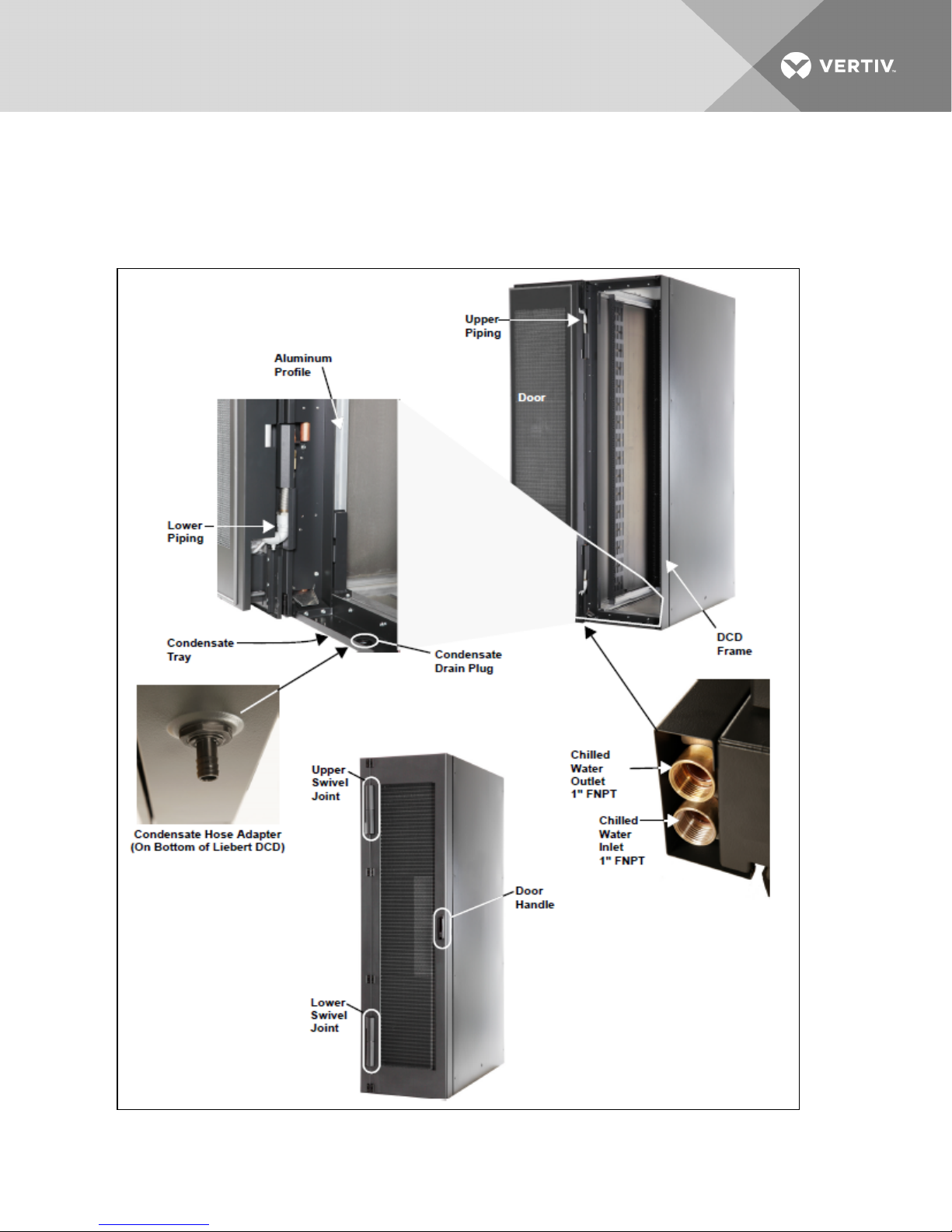
LIEBERT DCDCOMPONENT LOCATIONS
Figure I.1 Liebert DCD Component locations
Vertiv | Liebert® DCD™ User Manual | 3
Page 8

MODEL NUMBER NOMENCLATURE
Table I.1 Configuration number—Unit code and component location
Model number - part 1/2 Model Details Part 2/2
1 2 3 4 5 6 7 8 9 10 11 12 13 14 15 16 17 18 19 20 21 22 23 24 25
D C D 3 5 A 6 3 3 0 0 0 0 0 0 G 0 0 0 0 S A 0 0 2
1 - 3— Product Name
• DCD = ENP DCD
4 - 5— Nominal CoolingCapacity
• 35 = 35 kW
6 — Rack Height
• A = 78-6/8" (2000mm)
7 —RackWidth
• 6 = 23-5/8" ( 600mm)
8 — Rack depth
• 3 = Third-Party Rack Adapter
• 0 = No Rack
9 — ChilledWater Connection - Hinge Position
• 3= Bottom - Left
10 —Options
• 0 = No Options
11 - 15— NotUsed
• 0 = No Options
16 Color
• G = RAL 7021 (dark gray)
17 - 20 — Not Use
• 0 = No Options
21 — PackagingType
• S = Seaworthy (Air Freight) - LongD istance ( Wooden Crate)
22 — SFA (Special Features)
• X = SFAs Included
• A = No SFAs
23 - 25 — RevisionIdentifier
• 002
Vertiv | Liebert® DCD™ User Manual | 4
Page 9

1 INTRODUCTION
1.1 References
This document must be used together with site-specific documentation and documentation for other
parts of the system.
1.2 Pre-Installation Checks
Check the received materials to be sure all required assemblies and parts have been received. Report any
external damage to the shipping company and your local Vertiv™ representative.
Table 1.1 Packing list
Part Part Number Quantity
TopSwivel Cover (Attaches to Frame) 309617P5 1
Bottom Swivel Cover (Attaches to Frame) 309617P6 1
TopSwivel Cover (Attaches to Door) 309617P7 1
Bottom Swivel Cover (Attaches to Door) 309617P8 1
Self-Adhesive Foam 309894P3 1
Fiber Washers 31074P1 2
Condensate Hose Adapter 080090620 1
Spring Nuts 000782699 16
Diamond Nuts 000770869 7
Grounding Wire
000797999 1
000798169 1
1.3 Installation Considerations
The Liebert DCD is designed for attachment to the rear of a computer cabinet with side panels. See
Mechanical Considerations on page13 for details.
NOTE: The cooling with Liebert DCD works only if a strict air separation exists between server cold air
intake and server warm air outlet. Unused rack spaces must be blocked with blanking plates. All
bushings (network cables, piping, etc.) must be sealed to prevent air leakage. Racks must have side
panels. The tops and bottoms of the racks must be sealed.
1.4 Room Preparation
The room should be well-insulated and must have a sealed vapor barrier. The vapor barrier in the ceiling
and walls can be a polyethylene film. Paint on concrete walls and floors should contain either rubber or
plastic.
NOTE: The vapor barrier is the most important factor in maintaining environmental control in the
conditioned space.
Outside or fresh air should be kept to a minimum when temperature and humidity must be tightly
controlled. Outside air adds to the site’s cooling, heating, dehumidifying and humidifying loads. Doors
must be properly sealed to minimize leaks and must not contain ventilation grilles.
Vertiv | Liebert® DCD™ User Manual | 5
Page 10

1.5 Storage and Transportation
• Keep the Liebert DCD in its original packaging, protected from the weather and in dry
conditions.
• Protect the unit’s working parts from sand, rain, dust and other particles and contaminants.
• Store at temperatures between -22°F and +122°F (-30°C and +50°C); the chilled water circuit
must be empty during storage.
• After storage for a year or longer, the water-bearing hinges must be inspected for functionality.
• Remove all packaging before starting the unit.
• Chilled water connections are not load-bearing and must not be used as handles.
• When transporting the Liebert DCD, always make sure the device is properly fastened and
secured against slipping.
WARNING! Risk of heavy module falling. Can cause equipment damage, injury and death.
Two properly trained and qualified people are required to move and install the module. The
Liebert DCD weighs 210lb. (95kg). It must be securely and properly fastened to the forklift or
pallet jack, if being used to move the unit.
NOTICE
Risk of a leaking coil due to freezing during improper storage. Can cause equipment and serious building
damage.
The heat exchanger and the supply pipes must be cleared of any water before the unit is stored, either
before storage or after removal from a cabinet. Compressed air can be used to remove the water. Remove
all the vents and the screws before storing.
Vertiv | Liebert® DCD™ User Manual | 6
Page 11

2 GENERAL PRODUCT INFORMATION
2.1 Product/System Description
The Liebert DCD is an air-water heat exchanger that is integrated into the rear door of a server rack. The
Liebert DCD meets the requirements of the EN 60950 standard. The design allows installation on the
back of a server cabinet while maintaining access to the back of the servers while the chilled water
connections remain stationary. The heat exchanger is suitable for absorbing up to 35kW heat loads from
server racks 24" (600mm) x 42U. It can be configured so that no heat is released in the installation area.
Heat produced by internal components (e.g., servers), is reliably removed by the door with a built-in
chilled water system or a chilled water distribution unit, such as the Liebert DCP™ (see Figure 2.1 below).
A chilled water distribution unit provides these benefits:
• Isolates the building’s chilled water circuit from the chilled water circuit in the data center. The
Liebert DCP circulates chilled water to Liebert DCD while preventing condensation by
maintaining the water temperature above the room dew point.
• Ensures the proper flow rate to the Liebert DCD. This is critical to achieve and maintaining the
needed capacity.
• Minimizes the possibility of a leak within the data center by separating the data center from
the building chilled water circuit. Should a leak occur within the data center, the volume of
water is limited to the amount in the secondary piping system instead of the amount in the
entire building chilled water system.
Figure 2.1 Generic piping layout
Room air is drawn in through the front of the rack and picks up heat from the servers. Cooling occurs
when the server exhaust air passes through the Liebert DCD’s heat exchanger (see Figure 2.2 on the
next page). The air is moved through the heat exchanger by the server fans.
The Liebert DCD is not expected to produce any condensation because of its location within the
conditioned space and if connected to a Liebert DCP or if the chilled water temperature is maintained
above the dew point. A condensate pan is provided as a precaution. It has a drain fitting to allow any
condensate to be emptied.
Vertiv | Liebert® DCD™ User Manual | 7
Page 12

Figure 2.2 Top view of rack with Liebert DCD
2.2 Checking and Unpacking
Upon arrival of the module and before unpacking it, verify that the labeled equipment matches the bill of
lading.
Inspect all items for visible and concealed damage. Damage should be immediately reported to the carrier
and a damage claim filed with a copy sent to Vertiv™ or to your sales representative. If concealed damage
is later found, report it to both the shipping company and your local Vertiv representative.
Check to be sure all required assemblies and parts have been received.
The Liebert DCD is shipped in protective packaging and secured to a pallet (see Figure 2.4 on page11).
Do not remove these protective items from the Liebert DCD before it is at the installation location.
Exercise care to prevent damage when unpacking and handling the Liebert DCD.
2.2.1 Recycle Packaging
All material used to package this module is recyclable. Please save the material for future use or dispose of
it appropriately.
Vertiv | Liebert® DCD™ User Manual | 8
Page 13

WARNING! Risk of heavy module falling. Can cause equipment damage, injury and death.
Two properly trained and qualified people are required to move and install the module. The
Liebert DCD weighs 210 lb. (95kg). Do not leave a Liebert DCD standing unattended on its side
or its end without adequate support to prevent it from falling over. The Liebert DCD must be
supported at all times or laid flat on protective material until it is installed.
CAUTION: Risk of sharp edges, splinters and exposed fasteners. Can cause injury.
Only properly trained personnel wearing appropriate safety headgear, gloves, shoes and
glasses should attempt to move, lift, remove packaging from or prepare the module for
installation.
NOTICE
Risk of a leaking coil due to freezing during improper storage. Can cause equipment and serious building
damage.
The heat exchanger and the supply pipes must be drained completely before the unit is stored.
Compressed air can be used to remove the water. Remove all the vents and the screws before storing.
NOTICE
Risk of improper storage. Can cause module damage and serious building damage.
Keep the module indoors and protected from dampness, freezing temperatures and contact damage.
NOTICE
Risk of damage from forklift. Can cause exterior and/or underside damage.
Keep the forklift’s tines level and at a height suitable to fit below the skid.
Figure 2.3 Recommended module handling equipment
Vertiv | Liebert® DCD™ User Manual | 9
Page 14

2.2.2 Module Handling
WARNING! Risk of heavy module falling. Can cause equipment damage, injury and death.
Two properly trained and qualified people are required to move and install the module. The
Liebert DCD weighs 210 lb. (95kg). Do not leave a Liebert DCD standing unattended on its side
or its end without adequate support to prevent it from falling over. The Liebert DCD must be
supported at all times or laid flat on protective material until it is installed.
Exercise care to prevent damage when unpacking and handling the module.
Use a forklift or pallet jack to move the Liebert DCD. If multiple Liebert DCD modules are delivered, they
will be shipped on a pallet with up to four modules. A pallet jack will be required to move these modules to
the installation location.
Ensure that the fork tine length is suitable to safely move the packaged module.
Units may be stacked up to four units high if multiple units are ordered. If stacked units are received, cut
the bands securing them together and place all packages on the floor beginning to unpack them.
Keep modules in the protective packaging until they have been moved to the installation site.
When handling and unpacking the module, exercise great care to prevent damage.
Do not lift modules higher than 6" (152mm) while moving them. If a unit must be lifted higher than 6"
(152mm), exercise great care and keep all personnel who are not helping move them at least 20feet (5m)
away from the modules.
Do not use module piping to lift or move the Liebert DCD.
2.2.3 Unpacking the Module.
WARNING! Risk of heavy module falling. Can cause equipment damage, injury and death.
Two properly trained and qualified people are required to move and install the module. The
Liebert DCD weighs 210 lb. (95kg). Do not leave a Liebert DCD standing unattended on its side
or its end without adequate support to prevent it from falling over. The Liebert DCD must be
supported at all times or laid flat on protective material until it is installed.
CAUTION: Risk of sharp edges and splinters. Can cause injury.
Only properly trained and qualified personnel wearing appropriate safety headgear, gloves,
shoes and glasses should attempt to move, lift, remove packaging from or prepare the unit for
installation.
Required Tools
• Utility knife
• Flat-blade screwdriver, claw hammer, pliers or crowbar
• Forklift, pallet jack or similar device
Vertiv | Liebert® DCD™ User Manual | 10
Page 15

Do not unpack the Liebert DCD before moving it to the installation location. Once at the installation point:
1. Multiple Unit Shipments—Cut the bands and place all packaged modules on the floor for
unpacking.
2. Slide the upper row of spring clips upward and remove them (Figure 2.4 below).
3. Remove the top cover and cross brace from the package.
4. Remove and set aside the hardware and key package.
5. Remove the remaining spring clips, side panels and any spacers from the package.
Figure 2.4 Removing packaging
6. Lay two pieces of protective material, each longer and wider than the Liebert DCD frame, on
the floor.
7. Remove foam packaging from both sides of the unit.
8. At least two properly trained and qualified people may lift the Liebert DCD frame off the pallet
and lay it on one piece of protective material.
9. Compare the serial tag information on the Liebert DCD to the bill of lading. If the information
does not match the product specified, contact your local sales representative.
10. At least two properly trained and qualified people may lift the Liebert DCD door off the pallet
and lay it on the second piece of protective material with the door handle facing up.
Vertiv | Liebert® DCD™ User Manual | 11
Page 16

This page intentionally left blank.
Vertiv | Liebert® DCD™ User Manual | 12
Page 17

3 MECHANICAL CONSIDERATIONS
3.1 Liebert DCD Dimensions
Figure 3.1 Liebert DCD door dimensions
3.2 Cooling Principle
The server fans force air heated by the rack equipment through the unit’s air-water heat exchanger
where it is cooled. The air side pressure drop-flow rate dependency curve is shown in Figure 8.7 on
page57.
Vertiv | Liebert® DCD™ User Manual | 13
Page 18

Figure 3.2 Side view of rack with Liebert DCD
NOTE: Before using the Liebert DCD, the system and rack equipment must be checked to determine
whether they match hydraulically. In particular, the server fans must be able to generate sufficient
pressure to drive the air through the Liebert DCD.
NOTE: In case of chilled water supply system failure, the cooling is provided either by adjacent Liebert
DCD’s and/or the room cooling system. In this case, the equipment waste heat is released into the
room.
3.3 Determining Placement in the Conditioned Space
Refer to site-specific drawings for exact placement. Efficient cooling depends on proper equipment
placement, proper use of plates in any voids in the rack and good cable management.
Ensure that there is 25.6" (649mm) clearance in the rear to allow the door to open fully.
3.4 Air Flow
The server fans draw air into the rack where the equipment heats it. The server fans force the heated air
across the Liebert DCD coil. The Liebert DCD has a low air-side pressure drop, similar to a rack with
perforated doors.
Vertiv | Liebert® DCD™ User Manual | 14
Page 19

Figure 3.3 Generic airflow diagram
NOTE: To provide optimal cooling, strict separation between the hot and cold air must exist within the
rack and all the bushings (network cables, piping, etc.) must be sealed to prevent air leakage. Air
bypass and recirculation can severely reduce the cooling effectiveness of the Liebert DCD.
Blanking plates must be installed in any voids in the rack to prevent air bypass and air recirculation.
Keep the Liebert DCD’s coils clear of any obstructions that may block the airflow.
Contact the factory for further information. Refer to the user manual supplied with the rack the Liebert
DCD is mounted on.
3.5 Water Quality
For reliable function of the Liebert DCD, chilled water must be available in an appropriate amount, at the
appropriate temperature and pressure. The water quality must be in accordance with VGB-R 455 P. (see
Water Quality on page50)
3.6 Water Temperature
The cold water supply temperature must be higher than the dew point temperature of the cold space.
Failure to maintain the cold water supply temperature above the room dew point will result in
condensation. The Liebert DCD is designed only for sensible cooling; dehumidification of the room by
means of the Liebert DCD must be avoided. The built-in condensate tray with condensate drain is
designed only for a short-term condensation.
Vertiv | Liebert® DCD™ User Manual | 15
Page 20

Table 3.1 Application conditions
OperatingA mbientTemperature 50°F - 95°F (10°C - 35°C) (Other Temperatures on Request)
Maximum Absolute Air Humidity on S ite 8g/kg
ChilledWater Temperature Intake 53.6°F (12°C) Other Temperatures on Request
ChilledWater Temperature Outlet 64.4°F (18°C) Other Temperatures onRequest)
Water Temperature Difference 10.8°F (6°K)
Use of Glycol On Request (Not Recommended)
ChilledWater Connection Rack - Rear S ide (Topor Bottom Connection); 1" NPT
Condensate Tray Drain Connection Rack - Rear S ide; 5/8"
Maximum OperatingPressure 145psi (10bar)
Vertiv | Liebert® DCD™ User Manual | 16
Page 21

4 INSTALLATION
These instructions apply only to installing the Liebert DCD on a DCM™ rack by Knurr®. For racks built by
other makers, refer to the instruction sheet shipped with the adapter kit to install the adapter and Liebert
DCD frame.
WARNING! Risk of heavy module falling. Can cause equipment damage, injury and death.
Two properly trained and qualified people are required to move and install the module. The
Liebert DCD weighs 210lb. (95kg). Do not leave a Liebert DCD standing unattended on its side
or its end without adequate support to prevent it from falling over. The Liebert DCD must be
supported at all times or laid flat on protective material until it is installed.
NOTICE
Risk of improper installation and commissioning. Can cause equipment damage.
Installation and commissioning of the Liebert DCD must be performed only by properly trained and
qualified personnel. All actions must be in accordance with regulations and the manufacturer’s
instructions.
NOTICE
Risk of improper assembly. Can cause unit to malfunction.
The Liebert DCD must be properly aligned and plumb with the rack to for the unit to function properly
and without water leaks. Use a carpenter’s level to make sure this requirement is met when commencing
the installation.
The hot and cold air within the case must be separated.
NOTICE
Risk of airflow obstructions. Can cause improper air circulation.
To ensure sufficient air circulation make sure there are no obstructions (e.g. packaging materials, tools
etc.) left in the unit or cabinet. In particular, check the Liebert DCD’s grids, heat exchanger, air intake and
the air outlet.
4.1 Liebert DCD Frame Preparations
The Liebert DCD mounts on the rear of the rack.
• Before attaching the frame: remove the rear door from the rack. Refer to the rack’s installation
manual for details.
• If the Liebert DCD was supplied with an aluminum profile and will be attached to a DCM rack:,
remove the profile from the Liebert DCD by removing the screws.
Vertiv | Liebert® DCD™ User Manual | 17
Page 22

NOTE: If installing the Liebert DCD on any type of rack other than the DCM, an adapter kit is necessary.
Follow the installation instructions included with the rack adapter kit for the specific rack. Once the
adapter kit and frame are installed, continue the installation, following the steps in Installing the Liebert
DCD Door on page22.
4.2 Installing the Liebert DCD Frame on a DCM Rack
4.2.1 Required Tools
• Phillips screwdriver, PH3
• Adhesive-backed foam (factory-supplied)
• Utility knife
• 8mm socket and driver
• Scratch awl
• Marker
• Adjustable wrench with a maximum adjustment size of 2 inches (51mm)
• Torque wrenches, 1-1/2in (38mm) and 1-7/16 (36mm)
Table 4.1 Required factory-supplied parts
Part Name Liebert Part # Quantity
Spring Nuts 000782699 16
Diamond Nuts 000770869 7
Self-Adhesive Foam 309894P3 1
Bolts N/A N/A
Condensate Dr ain Kit N/A N/A
1. After removing the packaging, lift the Liebert DCD from the pallet or from the protective
material.
2. Align the frame of the Liebert DCD with the rear of the equipment rack.
• Bottom Chilled Water Connections: ensure that the chilled water connections are
pointing down (see on page3).
• Top Chilled Water Connections: rotate the frame 180°. Align the frame of the Liebert DCD
with the rear of the equipment rack.
3. Use a marker or scratch awl to mark the positions for the 17 bolts that will attach the frame to
the DCM (refer to Figure 4.1 on the facing page). Bolts will be inserted in:
• Five frame holes on the aluminum frame member on the door handle side of the rack.
• Three spring nuts near the top of the hinge side of the rack
• Three spring nuts near the bottom of the rack
• Three diamond nuts in the face of the rack’s top frame member
• Three diamond nuts in the face of the rack’s bottom frame member
Vertiv | Liebert® DCD™ User Manual | 18
Page 23

Figure 4.1 Position of frame holes, spring nuts and diamond nuts on the DCM
Vertiv | Liebert® DCD™ User Manual | 19
Page 24

4. Lay the Liebert DCD frame on the protective material.
5. Insert the spring nuts into the groove of the vertical aluminium profile (see Figure 4.2 below).
6. Move spring nuts to the marked positions using a scratch awl or similar tool.
Figure 4.2 Spring nuts
7. Insert three diamond nuts into the groove of each horizontal member of the rack aluminium
profile in the marked positions (see Figure 4.1 on the previous page). The diamond shape
prevents them from turning while being tightened
8. Attach the self-adhesive foam strip on the hinge side of the aluminium profile to seal the gap
between the rack and the Liebert DCD’s frame.
9. Trim the foam strip if necessary (see Figure 4.3 below).
Figure 4.3 Applied foam strip
10. Install the condensate drain assembly (refer to Figure 4.4 on the facing page).
a. Get the condensate drain parts from the parts bag.
b. Press the Condensate Hose Adapter into the top half of the drain assembly until it snaps
into place. The top of the Condensate Hose Adapter will extend above the top half of the
drain assembly.
c. Put the O-ring seal on the insert.
d. Insert the assembly in the top of the condensate drain hole.
e. Screw the nut onto the top half of the assembly, tightening it firmly by hand.
Vertiv | Liebert® DCD™ User Manual | 20
Page 25

Figure 4.4 Condensate drain assembly
11. Connect the Condensate Hose Adapter to the Condensate Tray.
12. Lift the Liebert DCD frame and align it with the server rack again.
Figure 4.5 Align the Liebert DCD frame with the rack
Vertiv | Liebert® DCD™ User Manual | 21
Page 26

13. Insert and partly tighten bolts to hold it in place.
NOTE: Performing this step may be easier if a board or similar object is placed under the DCD frame to
hold it in place.
14. Insert and lightly tighten the bolts, working all around the perimeter to prevent the frame from
twisting and to ensure the parts fit properly (see Figure 4.6 below).
15. Torque the screws all around the perimeter to 2 ft-lb (3 Nm).
16. Verify that the frame is not twisting.
Figure 4.6 Tighten screws on frame
17. Thread the brass swivel fitting to the frame by hand to ensure the threads mate properly.
18. Hold the brass body so that it does not rotate and use a torque wrench to tighten to 64 ft-lb
(85Nm).
Figure 4.7 Brass swivel fitting threaded onto Liebert DCD pipe
4.3 Installing the Liebert DCD Door
Required Tools
• Socket hexagonal screw driver - (Allen) 8mm for M5 screws (5/16")
• Torque wrench
• Phillips screw driver PH3
Vertiv | Liebert® DCD™ User Manual | 22
Page 27

• Utility knife
WARNING! Risk of heavy module falling. Can cause equipment damage, injury and death.
Two properly trained and qualified people are required to move and install the module. The
Liebert DCD weighs 210 lb. (95kg). Do not leave a Liebert DCD standing unattended on its side
or its end without adequate support to prevent it from falling over. The Liebert DCD must be
supported at all times or laid flat on protective material until it is installed.
1. Attach the three door hinges to the Liebert DCD door with the supplied screws.
2. Turn the Liebert DCD face down (handle side down) and lay it on the protective material.
3. Vent the low-pressure holding charge in the Liebert DCD by removing the cap on the
Schrader valve and depressing the valve pin.
4. Replace and secure the cap on the Schrader valve.
Figure 4.8 Schrader valve
5. Loosen the coil plug. This requires two adjustable wrenches in the wrench arrangement shown
in Figure 4.9 on the next page.
One wrench holds the Coil Inlet Fitting stationary and the other turns the plug to remove it.
NOTICE
Risk of improper coil plug removal. Can cause damage to the coil.
It is imperative that the coi inlet fitting is held stationary and the coil plug is is turned. Turning the coil
inlet fitting can damage the coil.
Vertiv | Liebert® DCD™ User Manual | 23
Page 28

Figure 4.9 Loosen the coil plug
6. Remove any debris and wipe the threaded surfaces clean.
7. Align the door to the frame (see Figure 4.10 on the facing page).
8. Set the door in the frame—Angle the bottom of the door toward the frame and insert the door
(see Figure 4.10 on the facing page).
NOTE: Performing this step may be easier if a board or similar object is placed under the DCD frame to
hold it in place.
Vertiv | Liebert® DCD™ User Manual | 24
Page 29

Figure 4.10 Frame and door alignment
9. Fasten the door hinges to the frame, starting with the top hinge and finishing with the bottom
hinge (see Figure 4.11 on the next page).
NOTE: Tilting the door may ease installing the hinge bolts.
Vertiv | Liebert® DCD™ User Manual | 25
Page 30

Figure 4.11 Liebert DCD door hinge location
10. Check that the door moves freely.
If there are any irregularities or roughness in the movement of the door:
• Check for obstructions or loosen screws of the hinges and adjust alignment.
• Tighten any loose screws.
11. Apply pipe wrap or plumber’s dope to the coil connection.
12. Thread one of the short, flexible pipes onto the coil connection by hand to ensure that the
threads properly mate (see Figure 4.12 on the facing page).
13. Tighten to 350 in-lb (39.5Nm).
NOTICE
Risk of improper tightening. Can cause equipment damage.
Turn only the nut on the flexible pipe when tightening this connection. Moving the coil connection may
damage the coil.
14. Pull the flexible piping slightly to elongate it enough to connect the union nuts.
NOTICE
Risk of overextending the flexible pipe. Can cause equipment damage.
Vertiv | Liebert® DCD™ User Manual | 26
Page 31

Pull the flexible piping slightly to elongate it. This makes the piping long enough to connect the union
nuts. Only a slight elongation is necessary. Pulling too hard will overextend the pipe, making it hard to fit
and possibly causing leaks.
Figure 4.12 Aligning pipes
15. Insert the sealing ring in the door’s lower piping (see Figure 4.13 below).
Figure 4.13 Inserting sealing ring
16. With the door fully open, use a torque wrench tighten the union nuts to 64 ft-lb (85Nm). If a
torque wrench is not available, use two wrenches to reduce the stress on the pipes (see Figure
4.14 on the next page).
• Open-end wrench 1-5/8" (41mm) or an adjustable wrench with maximum size of 2" (51mm)
• Open-end wrench 1-7/16" (36mm) or an adjustable wrench with maximum size of 2"
(51mm)
Vertiv | Liebert® DCD™ User Manual | 27
Page 32

Figure 4.14 Tightening piping
17. Check to ensure the door swings freely.
4.4 Installing the Liebert DCD Swivel Joint Covers
Too Required
• Socket hexagonal screw driver - 5/16" Allen (8mm) for M5 screws
The Swivel Joint Covers can be identified by the number of identification holes on each cover.
Vertiv | Liebert® DCD™ User Manual | 28
Page 33

Figure 4.15 Swivel joint cover identification and location
1. Open the Liebert DCD door; the door must be open for the Swivel Joint Covers to be installed.
2. Install the outer Swivel Joint Covers on the door (see Figure 4.16 below)
3. Install the inner Swivel Joint Cover on the frame (see Figure 4.17 on the next page).
Figure 4.16 Outer swivel joint cover locations
Vertiv | Liebert® DCD™ User Manual | 29
Page 34

Figure 4.17 Inside swivel joint cover locations
4. Fasten screws using the hexagonal screwdriver or socket wrench.
5. Connect the earth (ground) wire of the door to the frame of the Liebert DCD (see Figure 4.18
below).
Figure 4.18 Securing ground wire
6. Use a “diode” or multimeter to determine that the connection is properly grounded.
7. Check functionality of the door lock. The Liebert DCD is equipped with a half-inch cylinder lock
and keys.
Vertiv | Liebert® DCD™ User Manual | 30
Page 35

4.5 Reversing Door Handle
If installing the Liebert DCD for top chilled water connection, the handle would be upside down. The
handle will function but can be reversed for convenience.
To reverse the handle:
1. Open the door and remove all the bolts holding the door handle and lock assembly, including
the four brackets. Studs and nuts secure the brackets to the door frame.
2. Flip the door handle and lock assembly 180 degrees and reattach it with the bolts and nuts.
3. Check the handle and lock to ensure they operate properly.
Figure 4.19 Reverse door handle
Vertiv | Liebert® DCD™ User Manual | 31
Page 36

This page intentionally left blank.
Vertiv | Liebert® DCD™ User Manual | 32
Page 37

5 PIPING
Refer to site-specific drawings for general locations of the piping connections. The drawings should
specify where the piping connects to the Liebert DCD.
NOTICE
Risk coil and piping rupture. Can cause equipment damage and major fluid leaks resulting in serious
building damage, expensive repair costs and costly system down time.
Thermal expansion of the cooling fluid without means of expansion can cause the coil and piping to
rupture, spilling cooling fluid in the conditioned space. This can be caused, among other ways, by closing
the ball valves on both the supply and the return pipes. Always allow for thermal expansion either by
leaving at least one of the valves open or by opening the Liebert DCD’s bleed valve (see Figure 5.11 on
page41).
5.1 System Connection Configuration
If possible when using a chilled water distribution unit such as the Liebert DCP™, connect the Liebert DCD
in an interlaced configuration (see Figure 5.1 below). In an interlaced configuration, half the cooling
modules in an aisle are connected to one chilled water distribution unit and the other half are connected
to another chilled water distribution unit. Interlacing the connection piping will keep half the Liebert DCD
units operating and maintain cooling in the conditioned space should one chilled water distribution unit
fail.
Figure 5.1 Typical Liebert DCD interlaced piping
Vertiv | Liebert® DCD™ User Manual | 33
Page 38

When using a chilled water distribution unit such as the Liebert DCP, a ring design (see Figure 5.2 below)
or Tichelmann ring (see Figure 5.3 below) design may be employed. In these designs, the pressure drop
for each of the units is approximately the same, which results in even cooling performance.
Figure 5.2 Ring piping
Figure 5.3 Tichelmann ring piping
However, if a ring configuration is not possible, connect the Liebert DCD units in a non-interlaced
configuration as shown in Figure 5.4 on the facing page.
Vertiv | Liebert® DCD™ User Manual | 34
Page 39

Figure 5.4 Typical Liebert DCD non-interlaced piping
5.2 Connection Methods and Points
Refer to site-specific drawings for general locations of the piping connections. For Liebert DCD
connection locations, refer also to Figure 5.5 below andFigure 5.6 on the next page.
The assembly and connection means used for piping the Liebert DCD system are the same as those used
in conventional chilled water systems. Observe all standard practices during installation and startup to
prevent damage and contamination. All piping must be ASTM Type L copper.
The Liebert DCD supply and return piping connection is 1" OD internal threaded copper pipe. Supply and
return pipes are marked by labels on the unit itself. Torque for this connection is 147lb/ft(200Nm).
5.3 Floor Cutout Dimensions for Installation with Bottom Connections
Figure 5.5 Floor cutout dimensions, width 23-5/8" (600mm)
Vertiv | Liebert® DCD™ User Manual | 35
Page 40

Figure 5.6 Floor cutout dimensions, unit with aluminum profile, width 23-5/8" (600mm)
5.4 Insulation
Insulate all piping for the Liebert DCD to minimize the possibility of condensation.
5.5 Chilled Water Distribution Units
Utilizing a chilled water distribution unit provides these benefits:
• Isolation of the building’s chilled water circuit from the chilled water circuit within the data
center. The Liebert DCP™ circulates the chilled water to Liebert DCD while preventing
condensation by maintaining the water temperature above the room dew point.
• Ensures that the proper flow rate to the Liebert DCD is occurring. This is a critical factor in
achieving and maintaining the needed capacity.
• Separation of the data center from the building chilled water circuit also minimizes the impact
of a leak within the data center. Should a leak occur within the data center, the volume of water
is limited to the amount within the secondary piping system instead of the entire building
chilled water system.
5.5.1 Recommended Pipe Size
Elbows and restrictions should be minimized to establish sufficient fluid flow.
Table 5.1 Recommended pipe sizes
Piping Run Nominal Pipe Size, inches
Supply or Return Mains 2-5/8
Supply or Return Branches >10 ft 1-3/8
Supply or Return Branches <10 ft 1-1/8
5.6 Open Loop Chilled Water Systems
Maintaining the proper chilled water flow rate is critical in achieving the Liebert DCD’s design capacity. If a
chilled water distribution unit, such as the Liebert DCP™, is not being used, steps must be taken to ensure
the proper flow at the unit is maintained.
Vertiv | Liebert® DCD™ User Manual | 36
Page 41

5.7 Chilled Water Connections
5.7.1 Strainer
Install a 20-40 mesh strainer on the chilled water supply to the Liebert DCP. The strainer is required to
prevent particles in the chilled water from entering the Liebert DCP’s heat exchanger. The strainer must
be no more than 10 feet (3m) from the Liebert DCP.
5.7.2 Service Valves
Install 1" ball valves (field-supplied/field-installed) on the supply and return lines to the Liebert DCD to
allow service on the unit without shutting down the entire system.
5.7.3 Balancing Valves
Install balancing valves (circuit setters) in the supply line to the unit. Refer to Capacity Performance on
page52 for the proper flow rate required to achieve the site-specific capacity
NOTICE
Risk of improper storage. Can cause frozen or damaged coil and piping, resulting in fluid leaks, equipment
damage and serious building damage.
The heat exchanger and the piping must be cleared of any water before the unit is stored. Compressed
air can be used to remove the water. Remove all the vents and the screws before storing. Vertiv™
recommends storing of the module indoors protected from freezing, dampness and contact damage.
Figure 5.7 Chilled water connections
5.8 Flexible Pipes
Liebert DCD Flex Pipe kits are available in 10ft. (3m) in nominal length with quick connections (see Figure
5.8 on the next page). The kit consists of the hose, a threaded adapter for to attach to the Liebert DCD
and an adapter to connect to the field header.
Vertiv | Liebert® DCD™ User Manual | 37
Page 42

Figure 5.8 Liebert DCD Flex Pipe connection kit and header adapter
Vertiv | Liebert® DCD™ User Manual | 38
Page 43

Figure 5.9 Pipe bend radius, acceptable and unacceptable
5.9 Connecting Liebert DCD Flex Pipe Hoses
1. Connect the supply hose header adapter to the supply header.
2. Connect the return hose header adapter to the return header.
3. Connect the supply hose door adapter to the Liebert DCD supply connection.
4. Connect the return hose door adapter to the Liebert DCD return connection.
5. Connect the hoses to the fittings. Tighten to 55 ft.-lb. torque. If a torque measuring device is
not available, hand tighten the connection, then tighten an additional 1/2 flat (1/12 turn).
6. Connect the supply hose to the supply header (see Figure 5.10 on the next page).
7. Connect the return hose to the return header (see Figure 5.10 on the next page).
Vertiv | Liebert® DCD™ User Manual | 39
Page 44

Figure 5.10 Hose connections to cooling water headers
5.10 Leak Checking
Notice
Risk of leaking water. Can cause equipment damage and serious building damage.
Check the chilled water system for leaks before commissioning. Check the chilled water pipe
connection to the heat exchanger regularly. Tighten this connection if necessary.
When setting up the heat exchanger for the first time, inspect the mechanical condition of the
chilled water supply and connection thoroughly.
• Confirm that the flow directions of field-installed components are correct.
• Confirm that all isolating valves are open.
• Test the water quality when filling the system (see Water Quality on page50)
• Set the pressure at 145 psig (10 bars) maximum for at least 30 minutes or according to local
codes.
• Repair any leaks.
5.11 Filling the Unit
If using a chilled water distribution unit, such as the Knurr® CoolTrans™ or Liebert DCP™, refer to its user
manual for instructions on filling the Liebert DCD™ and starting the system.
5.11.1 Bleeding Air from Liebert DCD
The Liebert DCD has two Schrader valves, one at the top and one at the bottom. The two valves permit
rotating the Liebert DCD so that the unit may have bottom or top chilled water connections. Air trapped
in the unit or piping must be bled from the valve at the top. Opening the lower valve will release water.
NOTICE
Risk of water release. Can cause equipment and building damage.
The Schrader valve at the upper side of the Liebert DCD must be used when bleeding air from the unit.
Opening the lower Schrader valve will release water.
1. Find the Schrader valve at the top of the Liebert DCD, (see Figure 5.11 on the facing page).
Vertiv | Liebert® DCD™ User Manual | 40
Page 45

2. Depress the pin to open the valve.
3. Keep the Schrader valve open until the water coming out has no bubbles.
Figure 5.11 Schrader valve location
Vertiv | Liebert® DCD™ User Manual | 41
Page 46

This page intentionally left blank.
Vertiv | Liebert® DCD™ User Manual | 42
Page 47

6 INSTALLATION CHECKLIST AND SYSTEM FILL FOR
STARTUP
Done
Checks to be Performed
Check device for damage upon receipt
Install andalignto server cabinet
Flexible hoses connected( optional) properly
Packagingr emoved fr om the L iebert DCD
All assembly tools removed
Bushings installed properly
Chilledwater connections leak-proof / pressure-tested
Air bledfrom coil
Chilledwater flow adjustedto proper flow rate
Condensate line connected(if applicable) and r outedto a suitable drain
Unused s erver space is blockedwithblankingpanels
Topand bottom of server cabinet are blocked and any cable entries are sealed to minimize air leakage.
(to be signed
upon completion)
Remarks
Location Date Installer Signature
Customer Site Name
Customer Site A ddress
Site Contact
Phone Number
Installer Name
Installer Address
AmbientRoom
Temperature
Room Humidity atSite
of Commissioning
°F (°C)
% Relative Humidity
Vertiv | Liebert® DCD™ User Manual | 43
Page 48

Liebert D CD Serial #
Comments
Check of alignment Yes No
Shippingdamage Yes No
If yes, has the shipper beennotified Yes No
Residual packaging removed Yes No
Assembly tools removed Yes No
Table 6.1 Building chilled water system
ChilledWater
Liebert D CD
Connectedto BuildingChilledWater? Liebert D CP™
ChilledWater Temperature
(primary)
ChilledWater Pressure
Connection
With Glycol GlycolType
Without Glycol
Supply °C °F
Return °C °F
Supply bar Supply psi
Return bar Return psi
Liebert D CD Flexible Hose
External Flow Regulator
External Isolation Valves
Mechanical Functions
Damage to HeatE xchanger/
Connections/ Fins/Tubes/S urface
Remarks
Thermodynamic Checks
Pipe Duct Inlets/Cable Sealed Yes No
Remarks
Condensed Dr ain Connected Yes No
Remarks:
Thermodynamic Checks
Condensate on CoilSurface Yes No
Vertiv | Liebert® DCD™ User Manual | 44
None Existing
Page 49

Remarks
ChilledWater E nteringHeat Exchanger °F °C
Chilledwater leaving heat exchanger °F °C
Cabinet Temperature in Frontof Heat Exchanger °F °C
Cabinet Temperature Behindof Heat Exchanger °F °C
ChilledWater S ystem Bled Yes No
ChilledWater S ystem Press ure Tested Yes No
Proper ChilledWater Flow RateSet to L iebert DCD Yes No
Volume Flow
Correctness of values above is hereby affirmed
Startup Performed By Date Signature
Customer Date Signature
GPM External
l/m External
Vertiv | Liebert® DCD™ User Manual | 45
Page 50

This page intentionally left blank.
Vertiv | Liebert® DCD™ User Manual | 46
Page 51

7 MAINTENANCE
CAUTION: Risk of improper repair and maintenance. Can cause reduced unit performance,
equipment damage and injury.
All maintenance and repair jobs must be performed by properly trained and qualified personnel.
All actions must be in accordance with regulations and the manufacturer’s instructions. Use
only Vertiv-approved tools and parts for maintenance and repair.
NOTICE
Risk of dirty heat exchanger. Can cause reduced unit performance (increased pressure drop or poor heat
transfer).
Clean the heat exchanger fins with a a vacuum cleaner, soft brush or compressed air.
7.1 General Maintenance
1. Check the heat exchanger for dirt and debris.
2. Check functionality of the isolation valves.
3. Check the chilled water system for leaks.
Vertiv | Liebert® DCD™ User Manual | 47
Page 52

This page intentionally left blank.
Vertiv | Liebert® DCD™ User Manual | 48
Page 53

8 SPECIFICATIONS
Table 8.1 Liebert DCD35™ specifications
HousingMaterial Steel Plate
Coil Material
AmbientOperatingTemperature °F (°C) 50 - 95 ( 10 - 35)
Maximum Absolute Humidity 8 g/kg
Dimensions, Door Only, inches (mm)
Height 78-3/4 (2000)
Width 23-5/8 (600)
Depth 6 (151)
Dimensions, Door with Aluminum Pr ofile, inches (mm)
Height 78-3/4 (2000)
Width 23-5/8 (600)
Depth 7-3/8 ( 186)
ShippingD imensions, inches (mm)
Height 24" (610)
Width 36" ( 914)
Depth 91 (2311)
Weight, lb (kg)
Unit Only 200 (90.7)
Shipping 375 (170)
ChilledWater Connections
ChilledWater S upply 1” NPT
ChilledWater Return 1” NPT
ChilledWater E nteringTemperature, °F ( °C) 53.6°F - 64.4°F (12°C - 18°C)
ChilledWater L eaving Temperature, °F ( °C) 64.4°F - 75.2°F ( 18°C - 24°C)
Maximum OperatingPressure bar (psi) 145 (10)
Exterior Finish Black Matte, Heat-Fused Powder Coat
Safety CSA Approved
Table 8.2 Replacement parts an accessories
Part Name Part #
ReplacementParts
TopSwivel Cover (Attaches to Frame) 309617P5 1
Bottom Swivel Cover (Attaches to Frame) 309617P6 1
TopSwivel Cover (Attaches to Door) 309617P7 1
Bottom Swivel Cover (Attaches to Door) 309617P8 1
Self-Adhesive Foam 309894P3 1
Vertiv | Liebert® DCD™ User Manual | 49
Quantity
Required
per Unit
Page 54

Table 8.2 Replacement parts an accessories (continued)
Quantity
Part Name Part #
Fiber Washers 310741P1 2
Condensate Hose Adapter 080090620 1
Spring Nuts 000782699 16
Diamond Nuts 000770869 7
Grounding Wire
Acces sories
Flexible Hose Kit 310530G1 1
000797999 1
000798169 1
Required
per Unit
8.1 Water Quality
To safeguard the maximum lifetime of air/water heat exchangers, the water used for chilling purposes
must meet the VGB Chilled Water Guidelines (VGB-R 455 P). The chilled water used must be soft enough
to prevent deposits, but it must not be too soft because that would lead to corrosion of the heat
exchanger.
The following table lists the most important impurities and measures for their removal.
Table 8.3 Water Impurity
Water Impurity or Condition Corrective Method
Particles (dp< 0.3 mm) Filter the water
Excessive hardness Soften the water by ion exchange
Moderate level of particles and hardeners Add dispersion or stabilizationagents
Moderate level of chemical impurities Add deadening agents and inhibitors
Biological impurities (bacteria and algae) A dd biocides
Vertiv™ recommends treating water to it get as closest as possible to the values in 8 on the previous page
Table 8.4 Hydrological data
HydrologicalData
pH values (7 - 10,5)
Carbonate hardness (3 - 8) °dH
Free carbon dioxide (8 - 15) mg/dm3
Combinedcarbon dioxide
Aggressive carbon dioxide
Sulfides
Oxygen
Chloride ions
Recommended
Purity L evels
8 - 15mg/dm
3
0mg/dm
< 10mg/dm
< 50mg/dm
< 250mg/dm
3
3
3
3
Vertiv | Liebert® DCD™ User Manual | 50
Page 55

Table 8.4 Hydrological data (continued)
HydrologicalData
Sulphate ions
Nitrates and nitrites
COB
Ammonia
Iron
Manganese
Recommended
Purity L evels
< 10mg/dm
< 7mg/dm
< 5mg/dm
< 5mg/dm
< 0.2mg/dm
< 0.2mg/dm
Conductivity < 30S/cm
Solid res idue from evaporation
Potassium manganese consumption
Suspendedmatter
Partial Flow Cleaning Recommended
Full Flow Cleaning
< 500mg/dm
< 25mg/dm
< 3mg/dm
3 -15 mg/dm
> 15mg/dm
3
3
3
3
3
3
3
3
3
3
3
Vertiv | Liebert® DCD™ User Manual | 51
Page 56

8.2 Capacity Performance
Figure 8.1 Performance @ 5.2m3/h
Vertiv | Liebert® DCD™ User Manual | 52
Page 57

Figure 8.2 Performance @ 22.9 US GPM
Figure 8.3 Performance @ 3.5 m3/h
Vertiv | Liebert® DCD™ User Manual | 53
Page 58

Figure 8.4 Performance @ 15.4 US GPM
Vertiv | Liebert® DCD™ User Manual | 54
Page 59

Figure 8.5 Performance @ 1.8 m3/h
Vertiv | Liebert® DCD™ User Manual | 55
Page 60

Figure 8.6 Performance @ 7.9 US GPM
Vertiv | Liebert® DCD™ User Manual | 56
Page 61

Figure 8.7 Air-side pressure drop
Figure 8.8 Water-side pressure drop
Vertiv | Liebert® DCD™ User Manual | 57
Page 62

Vertiv | Liebert® DCD™ User Manual | 58
Page 63

Page 64

VertivCo.com | Vertiv Headquarters, 1050 Dearborn Drive, Columbus, OH, 43085, USA
© 2017 Vertiv Co. Allrights reserved. Vertiv and the Vertivlogo are trademarks or registered trademarks of VertivCo. Allother names and logos referred to
are trade names, trademarks or registered trademarks of their respective owners. While every precaution has been taken to ensure accuracy and
completeness herein, Vertiv Co. assumes no responsibility, and disclaims allliability, for damages resultingfrom use of this information or for anyerrors or
omissions. Specificationsare subject to change without notice.
SL-17307_REV3_10-17/590-1699-501A
 Loading...