

Page 1
Technical Data
Manual
Keeping Business in Business
Liebert
LPN: SLE CP TDM E.1
HPN: 272030 (17/6/99)
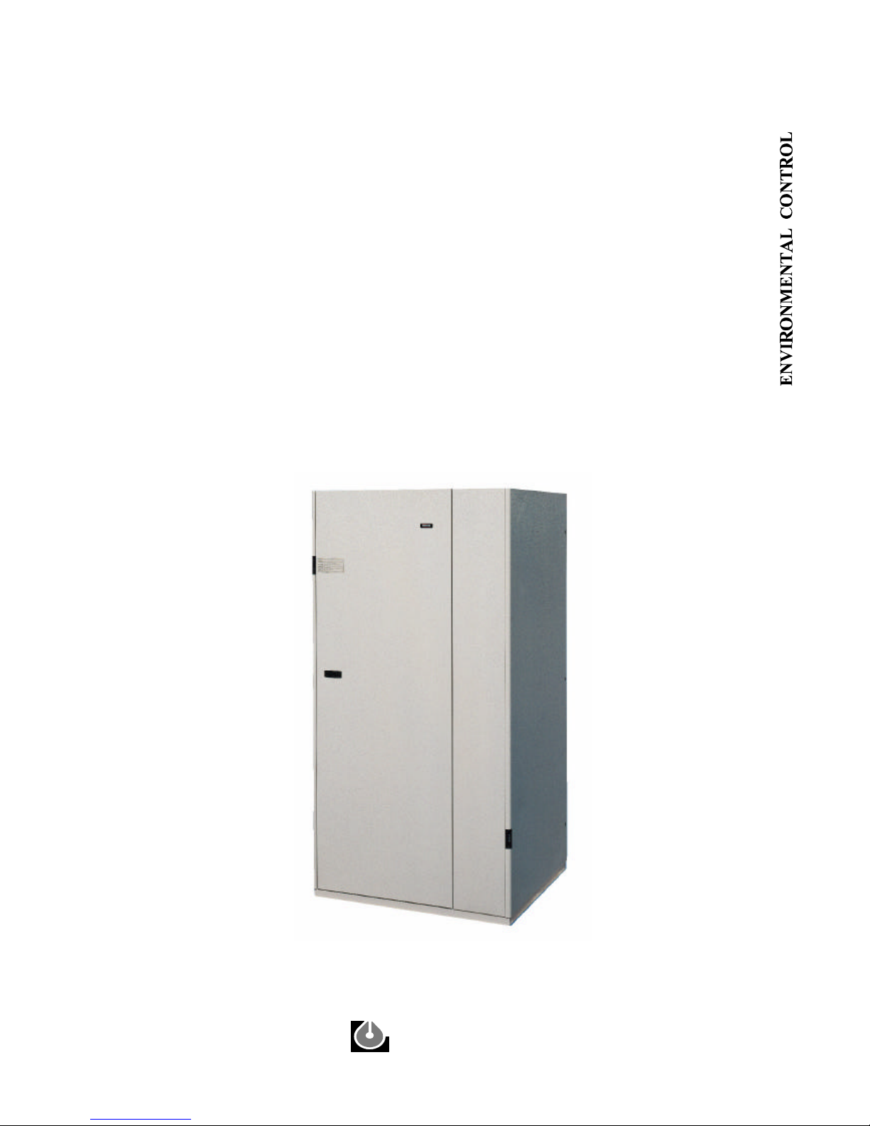
Challenger
Plus
Page 2

Page 3

Ta ble of Con tents
No men cla ture 1
In tro duc tion 2
Stan dard fea tures - all models 6
Stan dard fea tures - DX mod els 9
Stan dard fea tures - chilled wa ter mod els 12
Op tional fea tures - all mod els 13
Air cooled data 18
Water cooled data 20
Air cooled dual source data 22
Water cooled dual source data 24
Free cool ing data 26
Chilled wa ter cooled data 28
Con denser match ing ta bles 30
Chilled wa ter data - all mod els 31
Elec tri cal data - all mod els 32
Sound data - all mod els 37
Tech ni cal data - op tional com po nents 39
Di men sional data - all mod els 47
Page 4

Page 5
No men cla ture
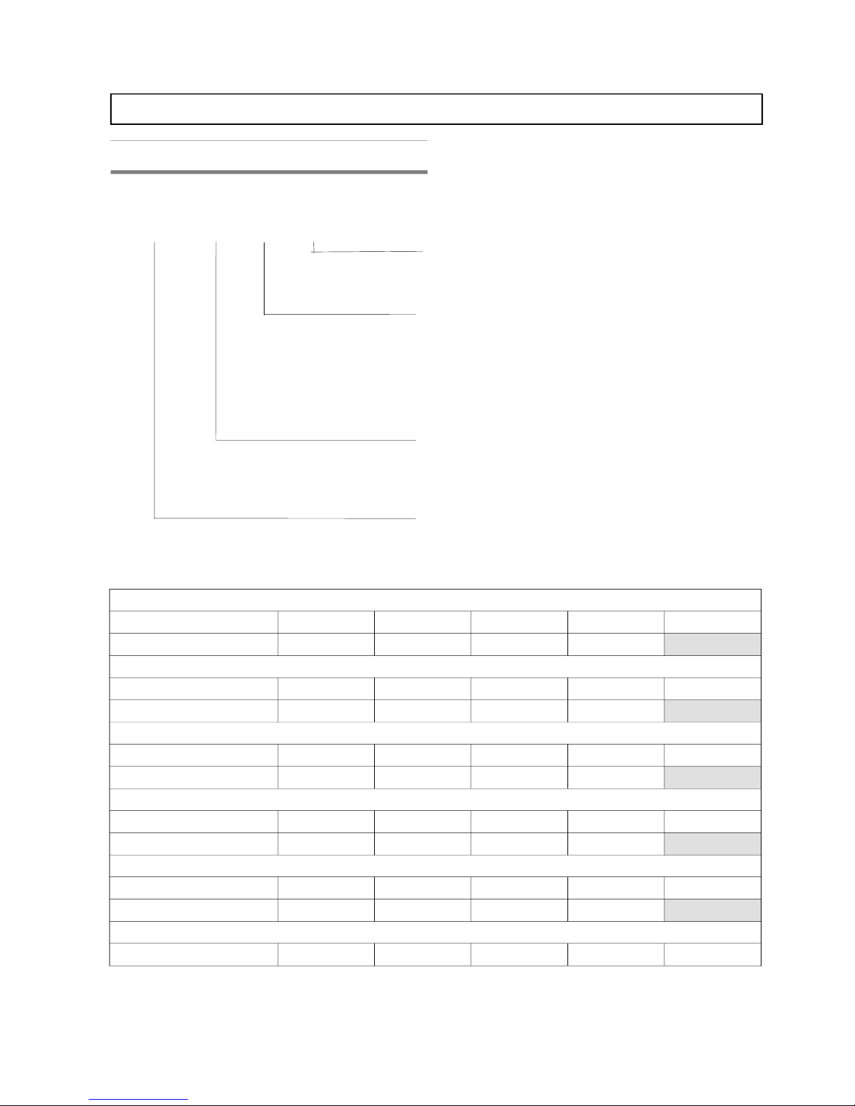
System nomenclature
SLE CP TDM E.1 (06/99) 1
Challenger Plus - Technical Data Manual
20 DA
Air Distribution:
D = Downflow
U = Upflow
System type:
A = Air Cooled
W = Water/ Glycol Cooled
F = Freecooling
D = Dual Source Air Cooled
H = Dual Source Water Cooled
C = Chilled Water Cooled
Model Number:
Nominal capacity in kW at 240C, 50% RH
Liebert Challenger Plus Unit
The range of mod els is as fol lows:
Air Cooled
Sin gle Cir cuit CP20A U/D CP24A U/D CP28A U/D CP34A U/D CP40A U/D
Dual Cir cuit CP26A U/D CP32A U/D CP42A U/D CP46A U/D
Wa ter /Gly col Cooled
Sin gle Cir cuit CP20W U/D CP24W U/D CP28W U/D CP34W U/D CP40W U/D
Dual Cir cuit CP26W U/D CP32W U/D CP42W U/D CP46W U/D
Free cool ing
Sin gle Cir cuit CP20F U/D CP24F U/D CP28F U/D CP34F U/D CP40F U/D
Dual Cir cuit CP26F U/D CP32F U/D CP42F U/D CP46F U/D
Dual Source Air Cooled
Sin gle Cir cuit CP20D U/D CP24D U/D CP28D U/D CP34D U/D CP40D U/D
Dual Cir cuit CP26D U/D CP32D U/D CP42D U/D CP46D U/D
Dual Source Wa ter Cooled
Sin gle Cir cuit CP20H U/D CP24H U/D CP28H U/D CP34H U/D CP40H U/D
Dual Cir cuit CP26H U/D CP32H U/D CP42H U/D CP46H U/D
Chilled Wa ter Cooled
Sin gle Cir cuit CP25C U/D CP35C U/D CP50C U/D CP60C U/D CP70C U/D
CP
Page 6

In tro duc tion
Pre ci sion en vi ron mental con trol may be de fined as the
si mul ta ne ous con trol of air tem pera ture, hu mid ity,
dis tri bu tion and clean li ness on a con tin ual, around- the- clock
ba sis.
Con ven tional build ing or ‘co mfort’ sys tems, as they are
called, are not de signed for this 24- hour, year- round us age;
they lack the abil ity to pro vide the pre ci sion and re li abil ity or
‘close con trol ‘ that is so criti cal to many ap pli ca tions.
The Lie bert Chal lenger Plus is a new se ries of air
con di tion ers de signed by Lie bert to meet the re quire ments of
data proc ess ing cen ters and other small and me dium sized
criti cal ar eas.
The Challenger Plus se ries com prises both di rect ex pan sion
units and chilled wa ter units. Cool ing ca paci ties range from
20 to 70 kW, for a to tal of 54 mod els. Di rect ex pan sion units
are equipped with com pli ant scroll com pres sors. The de sign
of the scroll com pres sor, en sures a con stant re frig er ant
pres sure, thus im prov ing re li abil ity, en ergy con sump tion and
sound emis sion.
Liebert technology and energy
efficiency
Lie bert has be come a world leader in pre ci sion
en vi ron mental con trol sys tems by pro vid ing maxi mum
en ergy ef fi ciency with out com pro mis ing pre ci sion and
re li abil ity.
Lie bert takes a no- compromise ap proach to en vi ron mental
con trol sys tem de sign. All en hance ments to en ergy
ef fi ciency are de signed to re duce op er at ing time of key
com po nents. This is ac com plished by tak ing ad van tage of
al ter nate sources of cool ing when avail able or, by re duc ing
com pres sor work load when the heat load in the criti cal space
is lower.
Applications
The Chal lenger Plus unit is ide ally suited for pre ci sion close
con trol of the fol low ing types of en vi ron ment:
• Data processing centers
• Telecommunications
• Industrial applications
The de sign of the Chal lenger Plus unit can vary de pend ing on
the ap pli ca tion, con sult the Lie bert Ap pli ca tions En gi neer ing
De part ment for spe cific de tails.
Manufacture
All units are built in ac cor dance Euro pean di rec tives
98/37/CE (89/392/CEE; 91/368/CEE; 93/68/CEE),
89/336/CEE; 73/23/CEE. The Lie bert Air Con di tion ing
Qual ity Sys tem is ap proved by LRQA in ac cor dance with the
stan dards UNI EN ISO 9001: 1994.
Each unit is sup plied com plete with a Test Cer tifi cate and
Dec la ra tion of Con formity.
All Chal lenger Plus units carry the “CE ” mark and fully
com ply with Euro pean Di rec tives con cern ing me chani cal,
elec tri cal and elec tro mag netic safety.
Features
• New fan sec tion - sin gle inlet, radial cen trifu gal fans (plug
fans) with back ward curved blades. Variable speed motor
with external rotor. Avail able static pres sure up to 350 Pa,
stan dard con figu ra tion
• High COP (Co-efficient Of Performance)
• High SHR (Sensible Heat Ratio)
• Low energy consumption; High EER (Energy Efficiency
Ratio)
• Low operating cost
• All materials used in the unit are fully recyclable
• Low internal air-side pressure drop
• High efficiency filtration, up to EU8 available
• Modular construction
• Sandwich construction of panels with non-flammable -
Class 0 (ISO 1182.2) insulation
2 SLE CP TDM E.1 (06/99)
Challenger Plus - Technical Data Manual
Page 7
In tro duc tion (con tin ued)
System types
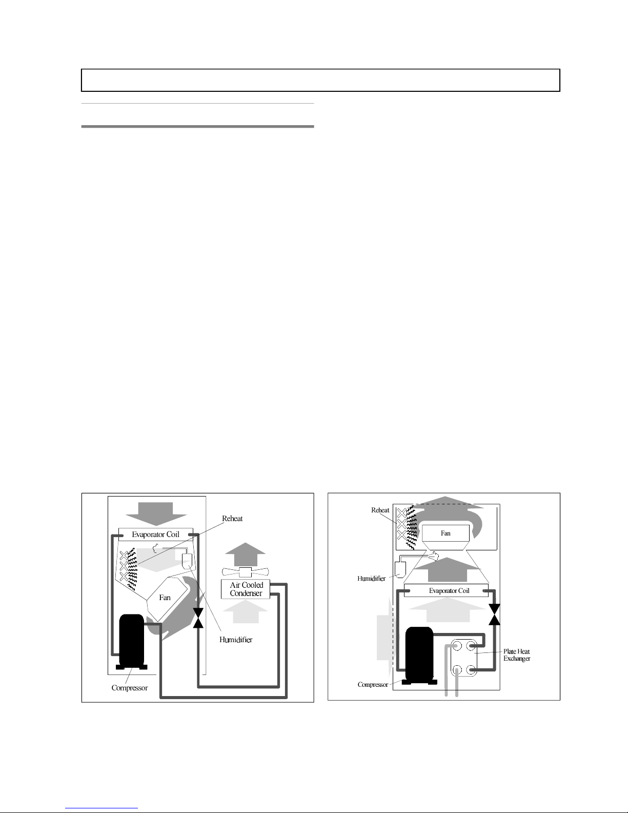
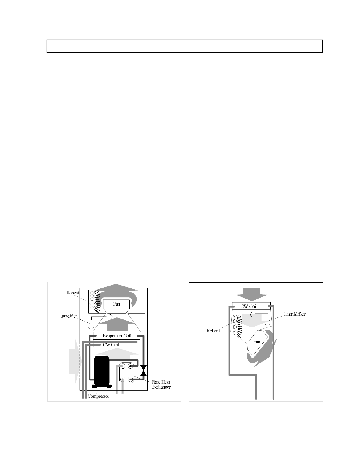
Air cooled units
Air cooled mod els con sist of an evapo ra tor coil, a com pli ant
scroll com pres sor, high and low pres sure switches, an
ex ter nally equal ised, ad just able, ther mo static ex pan sion
valve, serv ice ports, re frig er ant line sight glass, liq uid
re ceiver with pressure- relief valve and fil ter drier. The units
are shipped with a hold ing charge of dry Ni tro gen.
Mod els CP20A, CP24A, CP28A, CP34A and CP40A are
sin gle cir cuit. Mod els CP26A, CP32A, CP42A and CP46A
are dual cir cuit.
Air cooled units re quire matched air cooled con dens ers. Fan
speed con trolled con dens ers are avail able from Lie bert for a
full range of out side am bi ent tem pera tures. Refer to the
Condensers Technical Data Manual (P/N SLE CD TDM) for
full details.
Wa ter/Gly col cooled units
Wa ter/Gly col cooled mod els con sist of an evapo ra tor coil, a
com pli ant scroll com pres sor, high and low pres sure
switches, an ex ter nally equal ised, ad just able, ther mo static
ex pan sion valve, serv ice ports, re frig er ant line sight glass,
fil ter drier, stainless- steel plate heat ex changer and a
head- pressure con trol valve (wa ter regu lat ing valve).
Pres sure re lief valves are fit ted down stream of the plate heat
ex changer. The re frig er ant cir cuits are pre charged with
re frig er ant in the factory.
Mod els CP20W, CP24W, CP28W, CP34W, CP40W are
sin gle cir cuit. Mod els CP26W, CP32W, CP42W and CP46W
are dual cir cuit.
The units op er ate with mains wa ter, cool ing tower wa ter or
wa ter in a closed cir cuit with an ex ter nal drycooler.
When op er at ing in a closed cir cuit, it may be nec es sary
(de pend ing on out side tem pera tures) to add mono eth yl ene
gly col to pre vent the wa ter freez ing in win ter, re fer to the unit
In stal la tion Man ual for ap pli ca ble per cent ages.
A pump is used to cir cu late wa ter (wa ter/gly col) through the
unit (not sup plied as standard).
If mains wa ter or tower wa ter is used, it is rec om mended to fit
a me chani cal fil ter on the wa ter line to pro tect the plate heat
ex changer against pos si ble im pu ri ties con tained in the wa ter
(for plate heat ex changer clean ing, re fer to the In stal la tion
Man ual).
SLE CP TDM E.1 (06/99) 3
Challenger Plus - Technical Data Manual
Fig ure 1 - Air Cooled Down flow Unit
Fig ure 2 - Wa ter/Gly col Cooled Up flow Unit
Page 8
In tro duc tion (con tin ued)
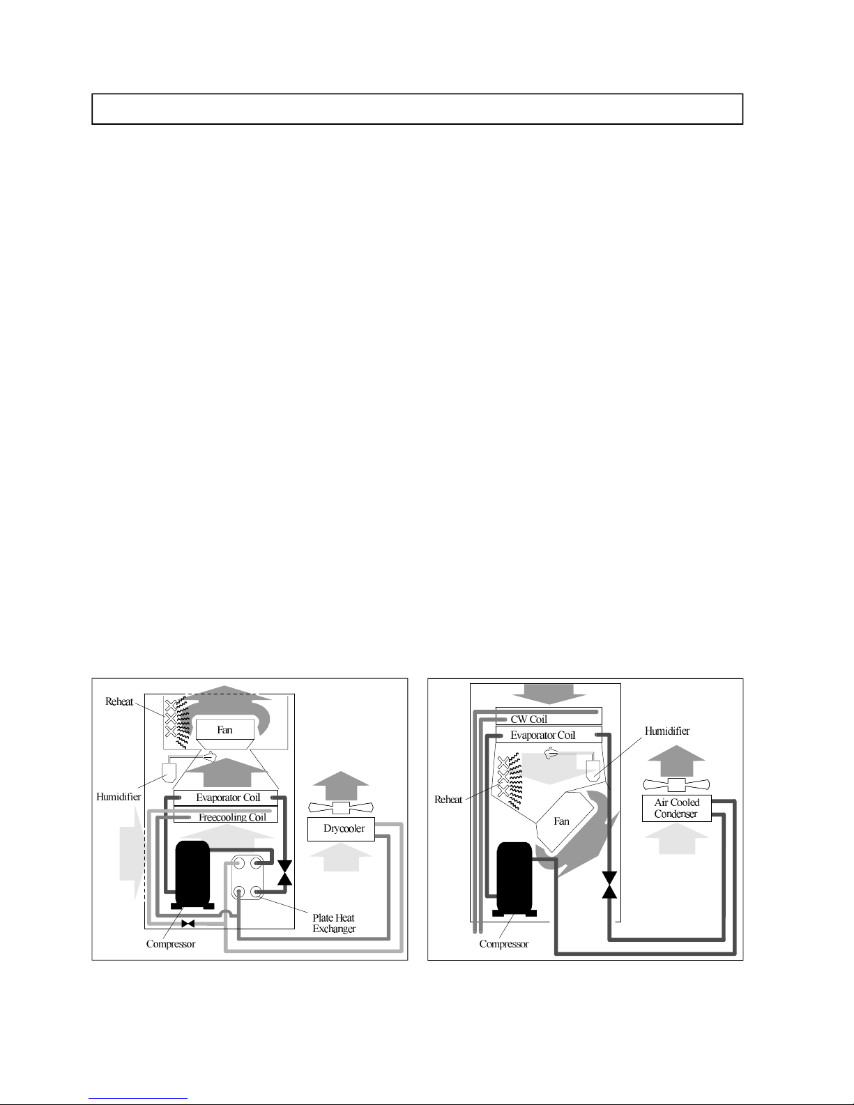
Freecooling units
Freecooling mod els con sist of an evapo ra tor coil, a
com pli ant scroll com pres sor, high and low pres sure
switches, an ex ter nally equal ised, ad just able, ther mo static
ex pan sion valve, serv ice ports, re frig er ant line sight glass,
fil ter drier, stainless- steel plate heat ex changer, a
head- pressure con trol valve (wa ter regu lat ing valve), a
2- way modu lat ing valve and a free cooling coil. Pres sure
re lief valves are fit ted down stream of the plate heat
ex changer. The re frig er ant cir cuits are pre charged with
re frig er ant in the factory.
Mod els CP20F, CP24F, CP28F, CP34F, CP40F are sin gle
cir cuit. Mod els CP26F, CP32F, CP42F and CP46F are dual
cir cuit.
The units op er ate with wa ter in a closed cir cuit from an
ex ter nal drycooler.
When op er at ing in a closed cir cuit, it may be nec es sary
(de pend ing on out side tem pera tures) to add mono eth yl ene
gly col to pre vent the wa ter freez ing in win ter, re fer to the unit
In stal la tion Man ual for ap pli ca ble per cent ages.
A pump is used to cir cu late wa ter (wa ter/gly col) through the
unit (not sup plied as standard).
Operation
Free cool ing units have two modes of op era tion, de pend ing
on the out side tem pera ture.
In nor mal op era tion, the unit cools the air in the con di tioned
space us ing the com pres sor and refrig er ant coil (di rect
ex pan sion).
When out side tem pera tures are low enough, wa ter from the
ex ter nal dry cooler is used to cool the air in the con di tioned
space di rectly us ing the Free cool ing coil. This tem pera ture is
the ZET or Zero En ergy Tem pera ture.
Dual source air cooled
Dual Source Air Cooled mod els con sist of an evapo ra tor
coil, a com pli ant scroll com pres sor, high and low pres sure
switches, an ex ter nally equal ised, ad just able, ther mo static
ex pan sion valve, serv ice ports, re frig er ant line sight glass,
liq uid re ceiver with pressure- relief valve, fil ter drier, 3- way
mo tor ised modu lat ing valve and a chilled wa ter coil. The
units are shipped with a hold ing charge of dry Ni tro gen.
Mod els CP20D, CP24D, CP28D, CP34D and CP40D are
sin gle cir cuit. Mod els CP26D, CP32D, CP42D and CP46D
are dual cir cuit.
Air cooled units re quire matched air cooled con dens ers. Fan
speed con trolled con dens ers are avail able from Lie bert for a
full range of out side am bi ent tem pera tures. Refer to the
Condensers Technical Data Manual (P/N SLE CD TDM) for
full details.
Op era tion
In nor mal op era tion, when the tem pera ture of the sec ond
source is low enough, the chilled wa ter coil is used to cool the
air in the con di tioned space. If the tem pera ture of the chilled
wa ter rises above the tem pera ture re quired to main tain the
load, chilled wa ter cool ing is stopped and the com pres sor is
started. The load is then main tained us ing dx cool ing.
4 SLE CP TDM E.1 (06/99)
Challenger Plus - Technical Data Manual
Fig ure 3 - Free cool ing Up flow Unit
Fig ure 4 - Dual Source Air Cooled Down flow Unit
Page 9
In tro duc tion (con tin ued)
Dual source water/glycol cooled
Dual Source Wa ter/Gly col cooled mod els con sist of an
evapo ra tor coil, a com pli ant scroll com pres sor, high and low
pres sure switches, an ex ter nally equal ised, ad just able,
ther mo static ex pan sion valve, serv ice ports, re frig er ant line
sight glass, fil ter drier, stainless- steel plate heat ex changer, a
head- pressure con trol valve (wa ter regu lat ing valve), a
3- way mo tor ised modu lat ing valve and a chilled wa ter coil.
Pres sure re lief valves are fit ted down stream of the plate heat
ex changer. The re frig er ant cir cuits are pre charged with
re frig er ant in the factory.
Mod els CP20H, CP24H, CP28H, CP34H, CP40H are sin gle
cir cuit. Mod els CP26H, CP32H, CP42H and CP46H are dual
cir cuit.
Nor mal Op era tion
In nor mal op era tion, when the tem pera ture of the sec ond
source is low enough, the chilled wa ter coil is used to cool the
air in the con di tioned space. If the tem pera ture of the chilled
wa ter rises above the tem pera ture re quired to main tain the
load, chilled wa ter cool ing is stopped and the com pres sor is
started. The load is then main tained us ing dx cool ing.
DX Op era tion
The units op er ate with mains wa ter, cool ing tower wa ter or
wa ter in a closed cir cuit with an ex ter nal drycooler.
When op er at ing in a closed cir cuit, it may be nec es sary
(de pend ing on out side tem pera tures) to add mono eth yl ene
gly col to pre vent the wa ter freez ing in win ter, re fer to the unit
In stal la tion Man ual for ap pli ca ble per cent ages.
A pump is used to cir cu late wa ter (wa ter/gly col) through the
unit (not sup plied as standard).
If mains wa ter or tower wa ter is used, it is rec om mended to fit
a me chani cal fil ter on the wa ter line to pro tect the plate heat
ex changer against pos si ble im pu ri ties con tained in the wa ter
(for plate heat ex changer clean ing, re fer to the In stal la tion
Man ual).
Chilled water cooled
Chilled wa ter mod els in cor po rate a chilled wa ter coil with a
three- way modu lat ing mo tor ised chilled wa ter valve and
in su lated pip ing.
SLE CP TDM E.1 (06/99) 5
Challenger Plus - Technical Data Manual
Fig ure 5 - Dual Source Wa ter Cooled Up flow Unit
Fig ure 6 - Chilled Wa ter Cooled Down flow Unit
Page 10
Stan dard fea tures - all sys tems
Access/Maintenance
Rou tine main te nance ac cess to re frig er ant cir cuit
com po nents, com pres sor, liq uid re ceiver, ther mal ex pan sion
valve, sight glass, fil ter dryer etc. is avail able through the
front panel of the unit. Serv ice ac cess to the air fil ter, the fan,
hu midi fier, elec tric panel, elec tronic con trol ler PCB, elec tric
re heats etc. is also through the unit front panel.
Cus tomer con nec tions to the re frig er ant cir cuit (hot gas and
liq uid line), cool ing wa ter cir cuits, mains power in put
sup ply, hu midi fier wa ter sup ply and con den sate drain lines
are lo cated in the base of the unit.
The com pres sor is housed in a sepa rate air tight com part ment
within the unit, al low ing ac cess to the com pres sor while the
unit is in op era tion.
Cabinet and panels
The cabi net is manu fac tured from zin tec, painted with
epoxy- polyester pow der paint and as sem bled us ing stain less
steel screws.
The front and rear pan els are double- skinned, with 22mm
fi ber glass in su la tion sand wiched be tween the pan els to
re duce noise emis sion and heat loss. The side pan els, which
are iso lated from the in side of the unit, are lined with 22mm
fi ber glass in su la tion sealed in an alu mi num foil.
The edges of the pan els are fit ted with seals to pre vent air loss
and to keep noise lev els to an ab so lute mini mum.
The struc ture is fully in com pli ance with Class 0 (ISO
1182.2). All sur faces in con tact with the air flow are
wash able in or der to re duce the for ma tion of bac te ria. All
ma te ri als used are CFC- free and may be re cy cled.
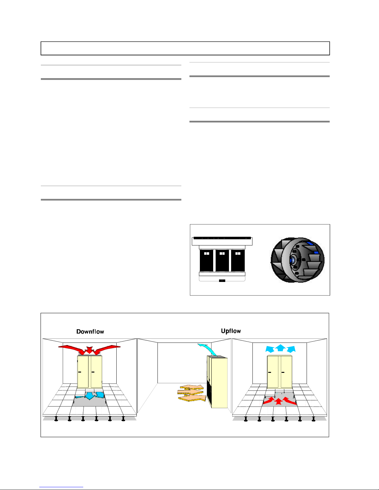
Air distribution
All units in the range are avail able in three con figu ra tions,
Down flow, Up flow Front Re turn and Up flow Bot tom
Re turn, re fer to Fig ure 7.
Fan section
The unit is fit ted with a direct- drive, sin gle in let back ward
curved, gal va nized painted steel ra dial cen trifu gal fan (plug
fan). The fan mo tor is a three- phase, 25- speed mo tor (speed
is ad just able via an au to trans former). The mo tor is rated to
IP44 and com plete with in ter nal ther mal pro tec tion.
The fan im pel ler is stati cally and dy nami cally bal anced and
equipped with self- lubricating bear ings. The fan is mounted
on vibration- absorbing rub ber sup ports to re duce vi bra tion
trans mis sion be tween the fan and the unit frame. This
vi bra tion at tenua tion helps to keep noise emis sion to a
mini mum. The mo tor is ca pa ble of pro vid ing the rated
air flow at ex ter nal static pres sures of up to 350 Pa.
6 SLE CP TDM E.1 (06/99)
Challenger Plus - Technical Data Manual
Fig ure 7 - Air Dis tri bu tion
Fig ure 8 - Autotransformer and Fan
Page 11

Stan dard fea tures - all sys tems (con tin ued)
Fil tra tion
The air fil ter is made of syn thetic fi ber cells in a card board
frame and is de signed to mini mise the air pres sure drop while
main tain ing maxi mum fil ter ef fi ciency. It is eas ily
ac cessed/re placed by open ing the front doors of the unit.
The guar an teed ef fi ciency is EU4 (Eu rov ent EU4/5, 30%
ef fi ciency), (G4, CEN stan dard). Optional fil tra tion lev els to
EU8 (G8) are avail able on re quest.
Pre fil ters are avail able on up flow mod els.
Electrical panel
The elec tric panel, lo cated at the front of the unit in an air tight
compartment, con tains the MCB’s, con tac tors, trans former,
con trol ler PCB and over load re lays etc. Each high volt age
sys tem com po nent is pro vided with a sepa rate over cur rent
pro tec tive de vice. All high- voltage com po nents are touch
pro tected by means of a plas tic cover. The elec tric panel
com plies with the EN 60204-1.
All units are de signed for op era tion at 400V/3ph/50 Hz ( +
10%) and are fit ted with a mains dis con nect switch.
Microprocessor controller Microface
The Mi cro face en vi ron mental con trol sys tem is
mi cro proc es sor based and can be pro grammed to match the
unique needs of any ap pli ca tion. The proc es sor in te grates the
sepa rate me chani cal and elec tri cal com po nents into a
‘state -of -the -art’ con di tioned space sup port sys tem that
con trols and moni tors tem pera ture, hu mid ity, air flow and air
clean li ness.
The con trol sys tem of fers a tai lored and well proven ad vance
in re li abil ity and con trol flexi bil ity al low ing the unit to
mod ify its per form ance in re sponse to chang ing criti cal space
con di tions.
The con trol ler al lows lo cal moni tor ing and pro gram ming of
the fol low ing room con di tions:
Tem pera ture (oC)
Tem pera ture set point (5.0oC – 40.0oC in steps of 0.1 oC)
Tem pera ture sen si tiv ity (1.0oC - 10oC in steps of 0.1 oC)
Hu mid ity (%RH)
Hu mid ity set point (20%RH - 80%RH in steps of 1%)
Hu mid ity sen si tiv ity (5%RH - 20%RH in steps of 1%)
The pa rame ters are enun ci ated us ing sym bols and text on an
LCD dis play. Nor mal op er at ing modes are in di cated by
sym bols on the dis play. Alarm con di tions ac ti vate a vis ual
in di ca tor.
The fol low ing alarms are stan dard:
• High temperature
• Low temperature
• Fan failure
• High pressure alarm – (compressorised systems only)
• Low pressure alarm - (compressorised systems only)
• Electrical reheat high temperature
• Memory failure
• Common alarm
Other alarms are also avail able when the rele vant op tion is
or dered with the unit (e.g. if a hu midi fier is or dered with the
unit, the High Hu mid ity, Low Hu mid ity etc. alarms are
en abled). For a full list of all the op tions and alarms avail able
with the Mi cro face con trol ler, re fer to the Mi cro face
Con trol ler Op era tion Man ual (P/N SLE MF OM).
The con trol ler also in cor po rates a se quen tial auto- restart
timer, al low ing field ad just able time de lays to be ap plied to
unit re start af ter a power loss (or other shut down). The tim ers
al low mul ti ple units to be re started while lim it ing
in stan ta ne ous in rush cur rent.
SLE CP TDM E.1 (06/99) 7
Challenger Plus - Technical Data Manual
Page 12

Stan dard fea tures - all sys tems (con tin ued)
Electric reheat
The three-stage re heat is of rigid de sign for ex tended
op era tional life. The re heat has am ple ca pac ity to main tain
room dry- bulb con di tions dur ing a sys tem call for
de hu midi fi ca tion. The low- watt den sity, elec tri cally
en closed ele ments are made of alu mi num sur rounded by high
ef fi ciency fins, re duc ing sheath tem pera tures and
elimi nat ing ioni sa tion. The re heat is phase- balanced.
Re heat con trol is of the ON-OFF type. The re heat is pro vided
with a man ual re set, re heat safety ther mo stat, to dis able the
re heat in the event of high tem pera ture.
The re heat safety stat. also in cor po rates a magneto- thermal
switch which pro tects the re heat from short cir cuits, should
the har ness be dam aged ac ci den tally.
Elec tric re heat can be com bined with hot gas or hot wa ter
re heat ac ti vated in dif fer ent stages.
Re fer to the Tech ni cal Data Ta bles for re heat ca paci ties,
FLA’s etc.
Humidifier
The unit is fit ted with an elec tronic steam bot tle hu midi fier
suit able for use with wa ter of vary ing degrees of hard ness,
pro vided that the wa ter is not treated or demineralized. The
hu midi fier is com plete with a wa ter inlet valve, a wa ter outlet
valve and a maximum wa ter level sensor.
The steam cyl in der is in stalled in the unit’s air tight
com part ment to avoid heat losses. Steam from the cyl in der is
mixed with the dis charge air from the evapo rat ing coil by
means of a cop per steam dis tribu tor.
The unit con trol ler moni tors the con di tion of the steam
cyl in der, and gen er ates an alarm when the cyl in der needs to
be changed. Cyl in der re place ment is easy and quick.
The hu midi fier is com plete with a self- adapting flow con trol
sys tem which moni tors wa ter con duc tiv ity and con trols the
elec tri cal cur rent pass ing through the cyl in der. Out put
ad just ment is from 30 - 100% via the unit con trol ler.
Hu midi fi ca tion con trol may be of the pro por tional or of the
on- off type, ac cord ing to the re quire ments of the in stal la tion:
On- off con trol is set as stan dard.
Re fer to the Op tional sec tion of the Tech ni cal Data Ta bles for
hu midi fier ca paci ties, FLA’s, etc.
Dehumidification
On air- cooled mod els, the unit de hu midi fies the air by
re duc ing the air flow across the coil (the fan is switched to a
lower speed) and switch ing on the com pres sor.
In chilled wa ter mod els, the unit de hu midi fies by fully
open ing the chilled wa ter valve.
In Dual Source units, the unit de hu midi fies us ing the
"Cur rent" cool ing source. If the cur rent source is DX, the unit
de hu midi fies the air by re duc ing the air flow across the coil
(the fan is switched to a lower speed) and switch ing on the
com pres sor. If the cur rent source is chilled wa ter, the unit
de hu midi fies by fully open ing the chilled wa ter valve.
In Free cool ing units, the unit dis ables free cool ing on a call
for de hu midi fi ca tion and de hu midi fies the air by re duc ing
the air flow across the coil (the fan is switched to a lower
speed) and switch ing on the com pres sor.
Packaging
As stan dard, the units are wrapped in bubble- wrap to pro tect
painted sur faces, en closed in a card board box and mounted
on a wooden pal let.
On re quest, for sea trans port etc., the units can be packed in
wooden crates or cases com plete with sili con des ic cant.
Warranty clauses
The war ranty does not cover any dam age or mal func tion of
the unit which may oc cur dur ing or as a re sult of op er at ing
the unit out side of the speci fied ap pli ca tion lim its.
Liebert does not accept responsibility for any damage caused
by improper use of the product.
8 SLE CP TDM E.1 (06/99)
Challenger Plus - Technical Data Manual
Page 13
Stan dard fea tures - DX sys tems (con tin ued)
Refrigerant circuit
Units are avail able as sin gle and dual cir cuit. The cir cuit(s)
con sist of a com pres sor, a ther mal ex pan sion valve, a liq uid
line sight glass, a fil ter dryer, an evapo ra tor coil, a liq uid
re ceiver (air cooled only) and high and low pres sure
switches.
For safety rea sons, (es pe cially dur ing ma chine start- up), it is
rec om mended to in stall a non- return valve(s) (sup plied as an
op tion, on re quest) on the liq uid line from the con denser, to
pro tect the com pres sor from un ex pected re frig er ant
mi gra tions. All low tem pera ture parts of the re frig er ant
cir cuit are in su lated as stan dard.
Evaporator
The evapo ra tor coils are de signed to pro vide maxi mum coil
area for more pre cise con trol of tem pera ture and hu mid ity.
With this com puter de signed coil ar range ment, low ve loc ity
air passes through the coil pro vid ing the most ef fec tive
sur face ex po sure with less tur bu lence and greater ef fi ciency
in the cool ing and de hu midi fi ca tion pro cesses. The coil is
de signed for the high sen si ble heat ra tio re quired by criti cal
spaces. The coil is tested to 30 Bar.
The evapo ra tor coil is made of cop per tubes with treated
alu mi num fins (to with stand cor ro sive at mos pheres). A
cor ro sion re sis tant drain pan is pro vided with the coil on all
mod els.
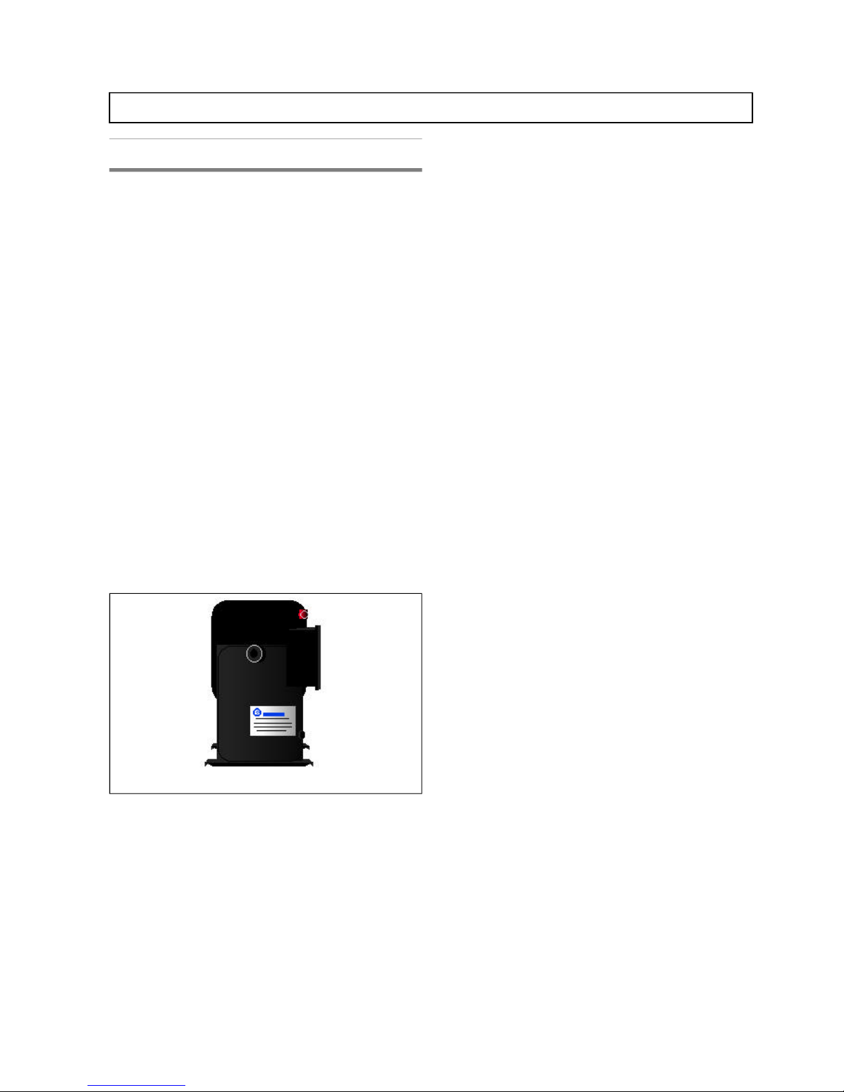
Compressors
The fully her metic com pli ant scroll com pres sor in cor po rates
sev eral safety fea tures for pro tec tion dur ing nor mal and the
oc ca sional ab nor mal op er at ing con di tions. They are:
• Self resetting overloads to sense excessive currents and
temperatures.
• An internal pressure relief valve which limits discharge
pressure to protect mechanical parts.
• Motor insulation that is resistant to chemical attack.
• Rubber mounting to ensure reduced compressor noise and
vibration.
• IP54 pro tec tion
Schrae der con nec tions are fit ted to the unit for serv ice
ac cess.
Refrigerant
R22 HCFC is the stan dard re frig er ant used in the Chal lenger
Plus range. An op tional “Green” re frig er ant, R407C is also
avail able. In this case the com pres sor is sup plied with es ter
oil. Air cooled units are shipped with a ni tro gen hold ing
charge, wa ter, dual source wa ter and free cool ing units are
charged with re frig er ant in the factory.
Sight glass
Re frig er ant line sight glasses serve as a means of quick vis ual
in spec tion to de ter mine if there is mois ture in the sys tem and
if the sys tem is prop erly charged.
Filter-dryer
Liq uid line filter- dryers en sure a clean, moisture- free
re frig er ant sys tem for ex tended com po nent life. The fil ter
drier is suit able for use with stan dard R22 and op tional “Zero
ODP” re frig er ant R407C.
Expansion valve
The ex ter nally equal ised, ad just able, ther mo static ex pan sion
valve smoothly con trols re frig er ant flow dur ing vary ing
in door heat loads and out door am bi ent tem pera tures by
con trol ling evapo ra tor su per heat.
Safety controls
Each com pres sor has a manual- reset high pres sure switch for
high pres sure pro tec tion and a high pres sure alarm cir cuit to
warn of high sys tem pres sures, al low ing cor rec tive ac tion to
be taken be fore a sig nifi cant loss of tem pera ture con trol
oc curs.
The low pres sure switch is auto- resetting and de tects low
pres sure con di tions such as loss of re frig er ant charge. The
pres sure switch cali bra tion val ues are shown in the
In stal la tion, Op era tion & Main te nance Man ual sup plied
with the ma chine.
Crankcase heaters
Crank case heat ers are sup plied with all com pres so rised
mod els. They main tain mini mum re frig er ant tem pera ture
and are en er gised while the unit is pow ered and the
com pres sor is off.
SLE CP TDM E.1 (06/99) 9
Challenger Plus - Technical Data Manual
Fig ure 9 - Scroll Compressor
Page 14

Stan dard fea tures - DX mod els (con tin ued)
Air cooled only
Liquid receiver
A welded steel liq uid re ceiver is pro vided to main tain
con stant and even re frig er ant flow to the ex pan sion valve, in
all cir cum stances. Shut- off valves are in stalled as stan dard on
the in let and out let of the re ceiver to as sist main te nance of the
cir cuit, if re quired.
A suita bly rated pres sure re lief valve is in stalled on the liq uid
re ceiver. The valve is equipped with a threaded con nec tion to
al low the re frig er ant to be dis charged out side of the
con di tioned space.
Air cooled condenser
A match ing Lie bert air cooled con denser with fan speed
con trol should be or dered with the unit. De tails of the
con dens ers are pro vided in this man ual, full de tails of all
con dens ers for all out door am bi ents are avail able in the
Con denser Tech ni cal Data Man ual, (P/N SLE CD TDM).
Note: The suggested condenser selections/performances for
each outdoor ambient are based on calculated data. The
actual selection of a condenser should always be verified on
the basis of the specific working conditions on each site.
Water cooled/freecooling units only
Plate heat exchanger
All wa ter cooled units (mod els W, H, F) are fit ted with a
brazed plate heat ex chang ers made of stain less steel. This
type of con denser is de signed for high ef fi ciency heat
ex change. The con denser is in ten tion ally over sized for the
ap pli ca tion to re duce pres sure drops (and the en ergy
con sump tion of the cir culation pump) in the wa ter sup ply and
thus al low the unit to op er ate with an ex ter nal wa ter cooler in
a closed cir cuit at high out door tem pera tures. Pres sure re lief
valves are fit ted down stream of the con denser. The valve is
equipped with a threaded con nec tion to al low the re frig er ant
to be dis charged out side of the con di tioned space.
Wa ter cooled units can op er ate with mains wa ter, cool ing
tower wa ter or wa ter in a closed cir cuit with an ex ter nal
dry cooler. Free cool ing units op er ate with wa ter in a closed
cir cuit from an ex ter nal dry cooler only.
When op er at ing in a closed cir cuit, it may be nec es sary
(de pend ing on out side tem pera tures) to add mono eth yl ene
gly col to pre vent the wa ter freez ing in win ter , re fer to the unit
In stal la tion Man ual for ap pli ca ble per cent ages.
A pump is used to cir cu late wa ter (wa ter/gly col) through the
unit (it is not sup plied).
If mains wa ter or tower wa ter is used, it is rec om mended to fit
a me chani cal fil ter on the wa ter line to pro tect the con denser
against pos si ble im pu ri ties con tained in the wa ter (for
con denser clean ing, re fer to the In stal la tion Man ual).
Drycooler
A dry cooler can be sup plied, if re quired. Full de tails of all
dry cool ers are avail able in the Dry cooler Tech ni cal Data
Man ual, P/N SLE DC TDM.
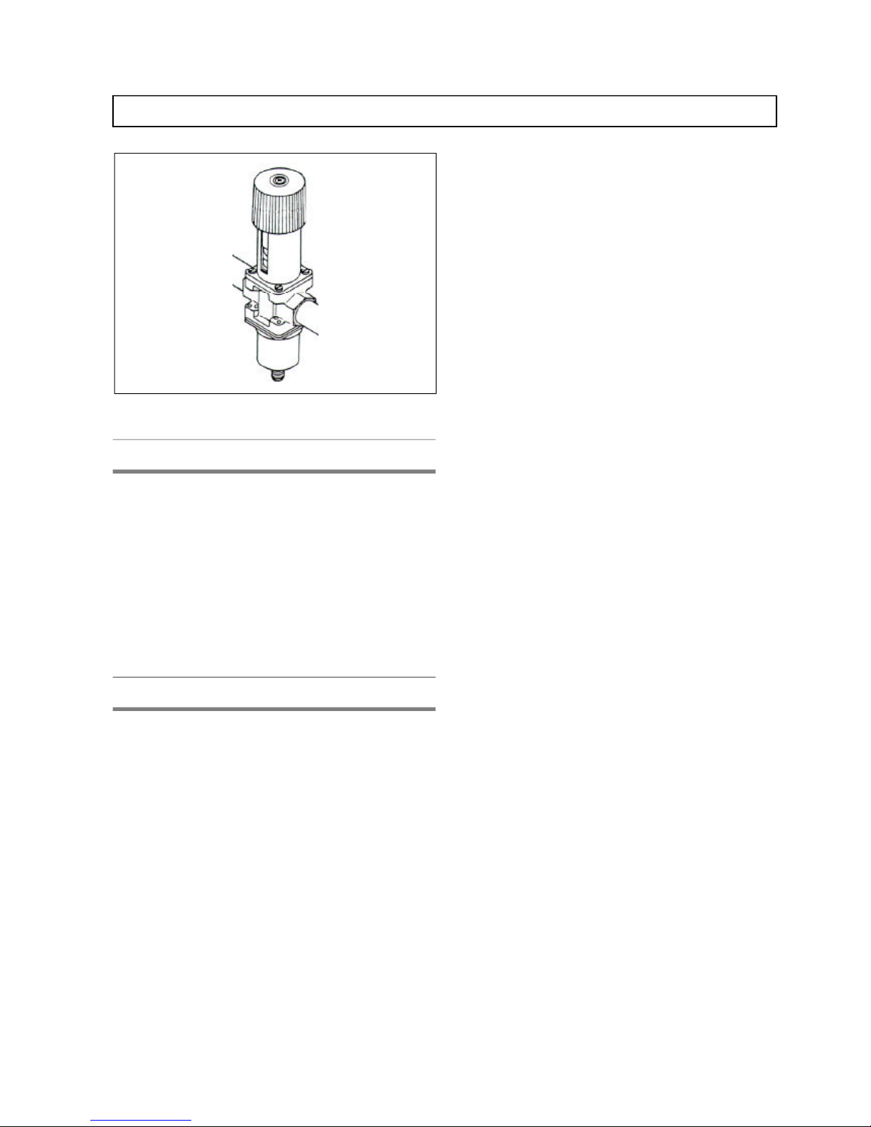
Head pressure control valve
Head pres sure op er ated regu lat ing valves ac cu rately con trol
the con dens ing tem pera ture and sys tem ca pac ity for vari ous
en ter ing fluid tem pera tures. A 2- way head pres sure con trol
valve is fit ted as stan dard on wa ter/gly col cooled, dual source
wa ter cooled and free cool ing units.
The valve con trols the con dens ing pres sure by regu lat ing the
wa ter flow to the plate con denser. It is in stalled at the
con denser out let with the pres sure probe po si tioned on the
re frig er ant dis charge line. It is auto mati cally closed when the
com pres sor is not op er at ing. It is sized for in let wa ter flow
tem pera tures lower than 17 0C re sult ing in low water- side
pres sure drops.
For higher wa ter in let tem pera tures, higher wa ter flowrates
are re quired and pos si bly spe cial wa ter regu lat ing valves,
con sult Lie bert Ap pli ca tions En gi neers for de tails.
Freecooling only
Freecooling coil
The Freecooling coil is lo cated on the re turn air side of the
evapo ra tor coil. Wa ter/gly col flow to the coil is con trolled by
a pre-piped 2- way modu lat ing motorised valve. When
sup plied with a coolant so lu tion of suf fi ciently low
tem pera ture, the coil is suf fi ciently sized to of fer an equal
cool ing ca pac ity to that ob tained us ing the re frig era tion
cir cuit. The coil is tested to 30 Bar.
2-way control valve
As the out door am bi ent drops to a suf fi ciently low
tem pera ture, the 2- way mo tor ised valve modu lates the flow
to the coil, as in a chilled wa ter sys tem. The valve in cludes an
op er at ing link age and elec tric mo tor.
10 SLE CP TDM E.1 (06/99)
Challenger Plus - Technical Data Manual
Page 15
Stan dard fea tures - DX mod els (con tin ued)
Dual source only
Dual source units con sist of the stan dard di rect ex pan sion
re frig era tion cir cuit and an ad di tional cool ing coil with a
three- way mo tor ised modu lat ing valve.
The ad di tional coil is lo cated on the re turn air side of the
evapo ra tor coil. Flow to the coil is con trolled by a pre- piped
3- way equal per cent age mo tor ised valve.
The nor mal con trol strat egy of the unit is to use the sec on dary
source (chil ler sup ply, pro cess wa ter sup ply etc.) to main tain
the room load un til a sen sor de tects that the sec on dary source
is no longer at the re quired tem pera ture. Di rect ex pan sion
cool ing is then switched on and main tains the load.
Operating limits (DX models)
Chal lenger Plus di rect ex pan sion units are de signed for
op era tion within the fol low ing work ing lim its (the lim its are
ap pli ca ble to newly com mis sioned ma chines which have
been cor rectly in stalled and main tained).
Indoor operating range
All models from 18.0°C, 45% R.H. to 27.0°C, 55% R.H.
To mini mise the pos si bil ity of wa ter carry over, (i.e. too
much con den sate on the evapo ra tor coil lead ing to the
for ma tion of wa ter drop lets), it is criti cal to en sure that the
la tent load (dif fer ence be tween to tal and sen si ble load) does
not ex ceed 5.5 kW.
Outdoor operating range (Air cooled - A, D)
Lower limit
-20°C with fan speed con trol in stalled in the con denser.
Upper limit
This is de ter mined by the ca pac ity of the con denser cou pled
to the unit (at the rele vant out door am bi ent). If the limit is
ex ceeded, the High Pres sure Switch will shut the com pres sor
down. The switch must then be manu ally re set af ter the
prob lem has been rec ti fied.
Condenser installation
Condenser above indoor unit
Maxi mum dis tance be tween in door unit and ex ter nal air
con denser: 30 me ters equiva lent length.
Con denser be low in door unit
Maxi mum geo detic height dif fer ence be tween con denser
and unit: 3 me ters.
Air flow
The mini mum and maxi mum air flows and avail able
Ex ter nal Static Pres sure are given in the Tech ni cal Data
sec tion of this man ual. The fan mo tor ther mal over load
pro tects the unit from any dam age which could re sult from
op er at ing out side the speci fied val ues.
Voltage tolerance
All mod els 400 V ± 10%
Fre quency tol er ance
50 Hz ± 2 Hz.
SLE CP TDM E.1 (06/99) 11
Challenger Plus - Technical Data Manual
Fig ure 10 - Head Pressure Control Valve
Page 16
Stan dard fea tures - chilled water mod els
Cooling coil
The large face area/low face ve loc ity, deep wave fin coil
al lows pre cise con trol of tem pera ture and hu mid ity dur ing
cool ing and de hu midi fi ca tion, and is de signed to op ti mize
fluid ve loc ity and mini mize pres sure drop. The full face area
is ac tive dur ing cool ing and de hu midi fi ca tion, re sult ing in
op era tional en ergy sav ing in the ap pli ca tion area. A
cor ro sion re sis tant drain pan is pro vided on all mod els. The
coil is tested to 30 Bar.
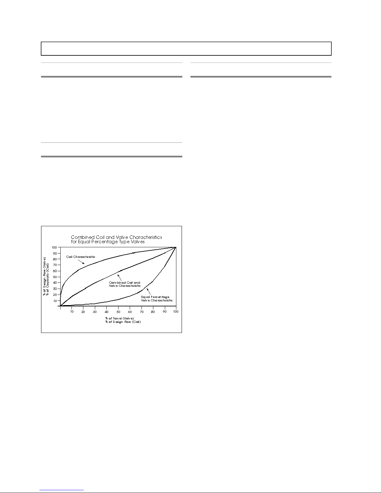
3-way control valve
The mo tor ised chilled wa ter valve pro vides equal per cent age
con trol ac tion in re sponse to room tem pera ture and hu mid ity
as sensed by the mi cro proc es sor. This re sults in a
pro por tional ra tio of ca pac ity to stem travel. The valve
in cludes an op er at ing link age and elec tric mo tor. The valve
can be manu ally ad justed to the closed po si tion (on the
coil- side of the valve) us ing the tool pro vided.
Operating limits
Chal lenger Plus chilled wa ter units are de signed for
op era tion within the fol low ing work ing lim its (the lim its are
ap pli ca ble to newly com mis sioned ma chines which have
been cor rectly in stalled and main tained).
Indoor operating range
All models from 18.0°C, 45% R.H. to 27.0°C, 55% R.H.
To mini mise the pos si bil ity of wa ter carry over, (i.e. too
much con den sate on the evapo ra tor coil lead ing to the
for ma tion of wa ter drop lets), it is criti cal to en sure that the
la tent load (dif fer ence be tween to tal and sen si ble load) does
not ex ceed 5.5 kW
Air flow
The mini mum and maxi mum air flows and avail able
Ex ter nal Static Pres sure are given in the Tech ni cal Data
sec tion of this man ual. The fan mo tor ther mal over load
pro tects the unit from any dam age which could re sult from
op er at ing out side the speci fied val ues.
Voltage tolerance
All mod els 400 V ± 10%
Fre quency tol er ance
50 Hz ± 2 Hz.
12 SLE CP TDM E.1 (06/99)
Challenger Plus - Technical Data Manual
Fig ure 11 - Equal Per cent age Valve Characteristic
Page 17
Op tional fea tures - all mod els
Hot gas reheat
Chal lenger Plus can be sup plied with a hot gas re heat coil if
re quired. This type of re heat uses the heat which is nor mally
re jected in the con denser to heat the air in the con di tioned
space, thus sav ing en ergy. A con trol valve pre vents the
re frig er ant from flow ing to the re heat ing coil when re heat is
not re quired. The re heat coil is sin gle or dou ble row
de pend ing on the model, and con structed of cop per tubes
with alu mi num fins.
When hot gas re heat is re quested, it is sup plied in con junc tion
with elec tri cal re heat in two stages as fol lows:
Stage 1: Hot gas re heat
Stage 2: Hot gas re heat + elec tri cal re heat
Note: The ca pac ity of the elec tri cal re heat in stage 2 is equal
to two thirds of the to tal ca pac ity of the stan dard elec tri cal
re heat for a given model.
Re fer to the Op tional sec tion of the Tech ni cal Data Ta bles for
re heat ca paci ties etc.
Hot water reheat
The eco nomi cal hot wa ter re heats are con trolled by a 3- way
(on/off) valve from the mi cro proc es sor con trol panel. The
sys tem is com pletely pre- piped and in cludes an air bleed
valve. The re heat coil is sin gle or dou ble row de pend ing on
the model, and con structed of cop per tubes with alu mi num
fins. The coil is tested to a pres sure of 30 bar.
A hot wa ter ther mo stat (pro vided by the cus tomer) is used in
the valve con trol se quence to de ter mine the avail abil ity of
re heat ca pac ity.
When hot water re heat is re quested, it is sup plied in
con junc tion with elec tri cal re heat in two stages as fol lows:
Stage 1: Hot water re heat
Stage 2: Hot water re heat + elec tri cal re heat
Note: The ca pac ity of the elec tri cal re heat in stage 2 is equal
to two thirds of the to tal ca pac ity of the stan dard elec tri cal
re heat for a given model.
Re fer to the Op tional sec tion of the Tech ni cal Data Ta bles for
re heat ca paci ties etc.
Non-return valves (models A and D)
Re frig er ant non- return valves for air- cooled units are
avail able as an op tion.
The valve is in stalled on the liq uid line, close to the
con denser and mounted ver ti cally.
Lie bert rec om mend that the valve be in stalled when the to tal
sys tem charge ex ceeds the speci fied val ues given in the
Op tional sec tion of the Tech ni cal Data Ta bles.
High efficiency filters
EU5 filters
Op tional 100mm EU5 high ef fi ciency fil ters are avail able for
all mod els. The high ef fi ciency fil ters are in ter change able
with the stan dard fil ters. The fil ters are EU5 (Eu rov ent 4/5),
fil tra tion class G4 (CEN stan dards).
EU6, EU7 and EU8 fil ters
Op tional 290mm high ef fi ciency fil ters, class EU6, EU7 and
EU8 (Eu rov ent 4/5), are avail able on re quest. The fil ters are
made of fi ber glass fil ter me dia. The fil ter me dia is
con structed in ”V” sec tions with a rigid ex ter nal frame to
with stand high pres sure drops and flow varia tions.
If these fil ters are or dered, a 600mm fil ter ple num is re quired
to house them. The ple num is of the same col our as the unit
and in stalled on the top of the unit. (Re fer to Op tions sec tion
of the Tech ni cal Data Ta bles for de tails).
SLE CP TDM E.1 (06/99) 13
Challenger Plus - Technical Data Manual
Fig ure 12 - EU6, EU7, EU8 Filters
Page 18

Op tional fea tures - all mod els (con tin ued)
Filter clog switch
An ad just able dif fer en tial pres sure switch can be fit ted to
ini ti ate a change fil ter alarm when a pre- selected pres sure
drop across the fil ter bank is ex ceeded.
Water detection sensors
A wa ter de tec tion sensor, con tain ing an iso lated switch that
closes when wa ter (or other con duc tive liq uid) is de tected by
the sen sor probes may be or dered as an op tion. The sen sor is
her meti cally sealed, ro bust and should be fit ted in the
lo ca tion where wa ter prob lems might oc cur.
Smoke alarm
A smoke de tec tor/alarm is avail able as an op tion. The smoke
de tec tor will ac ti vate the alarm and stop the unit if smoke is
de tected in the re turn air. The sen sor is an op tic smoke
de tec tor (Tyn dall ef fect) which is in sen si tive to light or air
move ment.
Firestat
A firestat/alarm is avail able as an op tion. The firestat
de ac ti vates the unit when the re turn air tem pera ture is too
high. The firestat can be mounted in the unit or re motely,
con sult Ap pli ca tions En gi neers for de tails. The de tec tor is
com plete with an NTC ther mis tor.
Environmental Alarm Package
The Elec tronic En vi ron men tal Alarm Pack age (EEAP) is a
re mote tem pera ture and rela tive hu mid ity sen sor (ad di tional
to the in ter nal sen sor) con nected to the unit con trol ler.
The sen sor can be in stalled up to 20m from the unit and
gen er ates an alarm if the tem pera ture or the rela tive hu mid ity
ex ceeds one of the 4 user- set lim its:
• HighTemperature Limit
(Adjustable from 10°C to 50 °C)
• Low Temperature Limit
(Adjustable from 0 °C to 30 °C)
• High Humidity Limit
(Adjustable from 30% to 99%)
• Low Humidity Limit
(Adjustable from 10% to 70%).
Fresh air kit
The fresh air in take kit is rec om mended for use where the
con di tioned space is con tinu ously occupied. The kit con sists
of a cy lin dri cal EU3 fil ter mounted in the unit which
con nects to a 100mm di ame ter duct (the flexi ble duct can
also be sup plied if the length is speci fied).
The fresh air is then mixed with the dis charge air from the
unit through a slot on the in take side of the fan.
Floorstand
Floor stands are avail able in a range of heights, 300mm,
500mm and 800mm. Each height of floorstand is fit ted with
ad just able legs (± 25mm). The floor stands per mit in stal la tion
and con nec tion of the sys tem prior to in stal la tion of the raised
floor.
Turning vane
A fac tory in stalled turn ing vane may be speci fied to di rect the
air as re quired within the floor stand.
14 SLE CP TDM E.1 (06/99)
Challenger Plus - Technical Data Manual
Fig ure 13 - Floorstand
Page 19

Op tional fea tures - all mod els (con tin ued)
Base module - upflow units only
A 200mm base mod ule can be sup plied on re quest to sup port
up flow Chal lenger Plus units. The mod ule is used when
cus tomer con nec tions must be made through the base of the
unit, but no false floor is avail able.
Al ter na tively the base mod ule can be used for bot tom air
re turn where there is no raised floor.
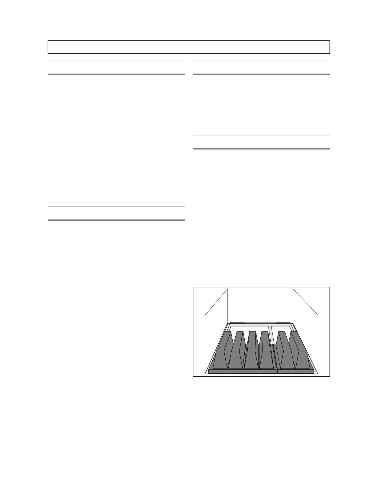
Sound attenuation package
In ap pli ca tions where sound emis sion from the unit is of
criti cal im por tance, a spe cial sound at tenu at ing cartridge,
at tached to the top of the unit, is avail able to re duce sound
lev els to an ab so lute mini mum.
The car tridges, made of a self- extinguishing ma te rial with a
high at tenua tion ca pac ity are guar an teed against
dis in te gra tion and re lease of par ti cles due to fric tion within
the duct.
It is pos si ble to in stall one or two rows of car tridges in the
plenum de pend ing on the sound at tenua tion re quired. A
sin gle row re quires a 600 mm high ple num, two rows re quire
a 1200 mm high plenum.
A single car tridge in a 600mm high ple num pro vides a noise
re duc tion of -8.5 dB(A) at 2 m in front of the unit and 1.5 m
from the ground. A sin gle car tridge in a 1200mm high
ple num pro vides a noise re duc tion of -13 dB(A) at 1 m in
front of the unit and at an an gle of 45o to the unit top.
A dou ble car tridge in a 1200mm ple num will pro vides a noise
re duc tion of -9.5 dB(A) at 2 m in front of the unit and 1.5 m
from the ground. It will provide a noise reduction of -14
dB(A) at 1 m in front of the unit and at an an gle of 45o to the
unit top.
Re fer to the Op tions sec tion of the Tech ni cal Data Ta bles for
fur ther de tails.
Special packaging
Where the unit is to be trans ported by sea or in other cases
where heavy duty pack ag ing is re quired, spe cial crat ing is
avail able.
This can con sist of ei ther a wooden crate over the stan dard
car board/bub ble wrap pack ag ing or the en tire unit can be
en cased in a wooden box.
Spe cial pack ing for sea trans port, con sist ing of a wooden box
or crate in ad di tion to nor mal card board, can be sup plied on
re quest.
SLE CP TDM E.1 (06/99) 15
Challenger Plus - Technical Data Manual
Figure 14 - Base Module
Fig ure 15 - Sound Attenuation Cartridge
Fig ure 16 - Special Packaging
Page 20

Op tional fea tures - all mod els (con tin ued)
Plenum
An in take/sup ply ple num is avail able for con nec tion be tween
the unit and a false ceil ing. The ple num is manu fac tured from
the same ma te rial and in the same col our as the unit.
The ple num con sists of sand wich pan els lined with class 0
(ISO 1182.2), 30 kg/m3 den sity, non- flammable in su la tion.
Avail able heights range from 600 mm to 1200 mm.
Plenum with fixed grille (upflow)
A sup ply air ple num with fixed hori zon tal air flow can be
in stalled on top of the unit. The 900 mm high ple num is
manu fac tured from the same ma te rial and in the same col our
as the unit.
The ple num con sists of sand wich pan els lined with class 0
(ISO 1182.2), 30 kg/m3 den sity, non- flammable in su la tion.
Plenum with adjustable louvered grille
(upflow)
A sup ply air ple num with ad just able (up and down) air flow
can be in stalled on top of the unit. The 900 mm high ple num is
manu fac tured from the same ma te rial and in the same col our
as the unit.
The ple num con sists of sand wich pan els lined with class 0
(ISO 1182.2), 30 kg/m3 den sity, non- flammable in su la tion.
Cau tion is ad vised against ex treme de flec tion of the lou vers
as this can ob struct the air flow and re duce the unit’s cool ing
ca pac ity.
Condensate pump
A con den sate drain pump can be sup plied if re quired. The
pump is com plete with a flow cut out switch al low ing the
pump to stop and re set auto mati cally. De pend ing on the unit
type, it can be sup plied fit ted or loose for field fit ting, con sult
Lie bert Ap pli ca tions En gi neers for de tails. The fol low ing
ta ble lists pump ca pac ity vs. avail able head.
Flow (l/s)
0.083 0.167 0.250 0.333
Avail able Head (kPa)
20 19 18 14
Air intake from the bottom (upflow
models)
Up flow mod els are nor mally front re turn. If re quired, they
can be sup plied as bot tom re turn. Bot tom re turn mod els are
fit ted with a blank front panel (this re duces the sound level of
the unit).
Dampers
Chal lenger Plus units can be pro vided with mo tor ised
shut- off damp ers for down flow mod els and grav ity-fed
damp ers for up flow models.
Al ter na tive re frig er ant R407C
An op tional “green” re frig er ant, R407C can be sup plied with
all com pres so rised mod els.
The com pres sor is filled with a spe cial es ter oil re quired for
R407C. Air cooled units are filled ex-factory with a holding
charge of dry nitrogen. Wa ter, Dual Source Wa ter and
Free cooling units are charged with R407C.
16 SLE CP TDM E.1 (06/99)
Challenger Plus - Technical Data Manual
Fig ure 17 - Ple num with grille
Page 21

Op tional fea tures - all mod els (con tin ued)
Hiromatic graphic
The Hi ro matic Graph ic is a purpose- designed con trol sys tem
for pre ci sion air- conditioning. It si mul ta ne ously moni tors
the criti cal space and sig nals alarms ei ther lo cally or
re motely. The graph ics screen dis plays all the ma jor
pa rame ters, in clud ing sym bolic rep re sen ta tion of unit
func tions, such as heat ing, cool ing etc.; in ad di tion
tem pera ture and hu mid ity varia tions with time can be
pre sented graphi cally on the screen. All di ag nos tic
pro ce dures, in clud ing the check ing and cali bra tion of in put
and out put sig nals, and of the mi cro proc es sor it self, can be
run from the front panel. The con trol ler al lows lo cal
moni tor ing and pro gram ming of the fol low ing room
con di tions:
Tem pera ture (oC)
Tem pera ture set point (5.0– 40.0oC in steps of 0.1oC)
Tem pera ture sen si tiv ity (1.0 - 10oC in steps of 0.1 oC)
Hu mid ity (%RH)
Hu mid ity set point (20%RH - 80%RH in steps of 1%)
Hu mid ity sen si tiv ity (5%RH - 20%RH in steps of 1%)
A full range of alarms, High and Low Tem pera ture, High and
Low Hu mid ity, Fan Fail ure, High and Low Pres sure etc. are
stan dard with the con trol ler.
Features
• Backlit LCD graphics display
• User interface via pushkeys
• Battery-backed clock for date/time and real time functions
• Password control for setpoints, unit/control setup and
service functions
• Graphics display of temperature and humidity over a 24
hour period
The Hi ro matic Graphic is menu- driven and user menu’s are
avail able in 10 lan guages. The Hi ro matic Graphic rec ords the
last 120 “events” (Alarms, Warn ings etc.) oc cur ring in the
sys tem along with a “Graphic Data Re cord” for the unit. The
Graphic Data Re cord dis plays the tem pera ture and hu mid ity
read ings for the last 24 hours (stored since the last start- up of
the unit).
The Hi ro matic Graphic con trols date and time func tions
us ing them as op er at ing in for ma tion for the cus tomer and as a
ref er ence when ever a status change oc curs, log ging the status
change in the “Status Re port”. De tails of the event which
oc curred, the date and time at which the event oc curred are
also stored. Us ing buff ered RAM, the Hi ro matic also stores
the op er at ing hours of each com po nent (com pres sor, fan,
elec tric heat ers, hu midi fier etc.) for each con nected unit.
A fur ther fea ture of the Hi ro matic Graphic is “Sleep Mode”.
Sleep Mode al lows units to be pro grammed to switch on and
off at dif fer ent times of the day, and on dif fer ent days of the
week.
The Hi ro matic Graphic can be sup plied in stalled in a unit, or
in kit form for in stal la tion in a re mote con trol panel.
BEMS Interface
The Hi ro matic Graphic al lows units on a net work to be
in te grated with the Hi ro link Com mu ni ca tions Bus when an
RS422 card is in stalled at the back of Hi ro matic. Hi ro matic
can con trol up to 8 Mi cro face units in this con figu ra tion and
com mu ni cate the rele vant data to Hi ro link.
Hi ro link works as a com mu ni ca tions man ager be tween the
Hi ro matic Graphic and Mi cro face units and in dus try
stan dard field bus ses and pro to cols used in Build ing
Man age ment Sys tems such as Mod- Bus, J- Bus, Satch well,
etc.
Note: For full de tails of the Hi ro matic Graphic, re fer to the
Hi ro matic Graphic Operations Man ual, (P/N SLE HG OM).
SLE CP TDM E.1 (06/99) 17
Challenger Plus - Technical Data Manual
Page 22

Air cooled data - down flow units (R407C)
+
18 SLE CP TDM E.1 (06/99)
Challenger Plus - Technical Data Manual
MODEL CP20AD CP24AD CP28AD CP34AD CP40AD CP26AD CP 32AD CP 42AD CP 46AD
Re frig er ant Cir cuit - Sin gle Dou ble
PER FORM ANCE DATA
(1)
Air Flow m3/h 5800 6600 9980 11040 12510 9980 11040 12510 13500
Avail able ESP
(2)
Pa 450 380 430 400 370 430 400 370 320
To tal Capacity kW 19.6 24.9 32.7 36.1 47.3 29.2 34.7 41.9 54.0
Sen si ble Capacity kW 18.8 23.2 29.5 33.5 42.6 28.0 33.3 41.1 47.0
Sen si ble Heat Ratio - 0.96 0.93 0.90 0.93 0.90 0.96 0.96 0.98 0.87
En ergy Out put/Input - 3.39 3.25 3.37 3.20 3.49 3.24 3.25 3.42 3.44
Sound Pres sure Level
(3)
dB(A) 51.1 54.4 56.4 57.5 59.0 56.4 57.5 59.0 60.8
Comp.Power Absorbed kW 4.80 6.37 7.53 8.91 10.93 6.84 8.32 9.60 12.76
Comp.Cur rent Absorbed A 11.1 11.8 14.7 16.2 18.9 2 x 6.5 2 x 8.0 2 x 11.1 2 x 11.8
Fan Power Absorbed kW 0.98 1.31 2.17 2.34 2.65 2.17 2.34 2.65 2.96
Fan Cur rent Absorbed A 3.9 4.2 2 x 4.1 2 x 4.1 2 x 4.2 2 x 4.1 2 x 4.1 2 x 4.2 2 x 4.3
To tal Power Absorbed kW 5.8 7.7 9.7 11.3 13.6 9.0 10.7 12.3 15.7
FAN SEC TION
Quan tity 1 2
Type - Sin gle in let, back ward curved, ra dial cen trifu gal fan (plug fan)
COM PRES SOR SEC TION
Quan tity 1 2
Type Scroll compressor
Rated power HP 6 7.8 9 10 13 2 x 4 2 x 5 2 x 6 2 x 7.8
EVAPO RA TOR COIL
Quan tity n. 1
Tubes/Fins Cop per tubes / Treated alu min ium fins
Coil Sur face Area m
2
0.74 1.49
Configuration - In clined
RE FRIG ER ANT CON NEC TIONS (Brazed, O.D.)
Hot Gas Line mm 18 22 28 16 18 22
Liq uid Line mm 16 18 22 14 16 18
DI MEN SIONS
Width mm 1000 1750
Depth mm 890
Height mm 1950
Foot print m
2
0.89 1.56
WEIGHTS
Net kg 380 385 580 585 590 590 595 600 605
Gross kg 385 390 585 590 595 595 600 605 610
+
R22 Capacities are approximately the same as R407C capacities + 5%. Consult Liebert Applications Engineers for specific details.
1
At the following standard conditions: 24°C db; 50% R.H. (17°C wb) - condensing temperature: 49° C.
Power Supply Voltage 400/3/50, 20Pa ESP (External Static Pressure)
2
Max available ESP at quoted airflow
3
Measured in front of the unit at 1m height, 2 m distance, in the free field, fan and compressor run ning, 20Pa ESP.
Note: Quoted capacities are gross capacities, for nett capacities, deduct fan motor kW. EER is based on i ndoor unit only. Unit air flow is quoted for standard
configuration, with a clean EU4 filter.
Page 23

Air cooled data - up flow units (R407C)+
SLE CP TDM E.1 (06/99) 19
Challenger Plus - Technical Data Manual
MODEL CP20AU CP 24AU CP 28AU CP34AU CP40AU CP26AU CP32AU CP42AU CP46AU
Re frig er ant Cir cuit Sin gle Dou ble
PER FORM ANCE DATA (1)
Air Flow m3/h 5785 6690 9820 10790 12465 9820 10790 12465 13201
Avail able ESP
(2)
Pa 450 380 430 370 330 430 370 330 280
To tal Capacity kW 19.4 24.7 32.5 36.3 47.0 29.3 34.4 40.8 53.0
Sen si ble Capacity kW 18.6 22.7 28.9 33.4 42.8 27.8 33.0 40.8 46.2
Sen si ble Heat Ratio - 0.96 0.92 0.89 0.92 0.91 0.95 0.96 1.0 0.87
En ergy Out put/Input - 3.28 3.17 3.28 3.09 3.35 3.18 3.08 3.21 3.28
Sound Pres sure Level
(3)
dB(A) 52.7 55.8 57.8 60.0 61.6 57.8 60.0 61.6 62.9
Comp. Power Absorbed kW 4.80 6.37 7.53 8.91 10.92 6.84 8.32 9.60 12.74
Comp. Cur rent Absorbed kW 11.1 11.8 14.7 16.2 18.9 2 x 6.5 2 x 8.0 2 x 11.1 2 x 11.8
Fan Power Absorbed kW 1.12 1.42 2.37 2.85 3.11 2.37 2.85 3.11 3.41
Fan Cur rent Absorbed A 4.1 4.3 2 x 4.1 2 x 4.3 2 x 4.4 2 x 4.1 2 x 4.3 2 x 4.4 2 x 4.4
To tal Power Absorbed kW 5.9 7.8 9.9 11.8 14.0 9.2 11.2 12.7 16.2
FAN SEC TION
Quan tity 1 2
Type Sin gle in let, back ward curved, ra dial cen trifu gal fan (plug fan)
COM PRES SOR SEC TION
Quan tity 1 2
Type Scroll compressor
Rated power HP 6 7.8 9 10 13 2 x 4 2 x 5 2 x 6 2 x 7.8
EVAPO RA TOR COIL
Quan tity 1
Tubes/Fins Cop per tubes / Treated alu min ium fins
Coil Sur face Area m
2
0.74 1.49
Configuration - In clined
RE FRIG ER ANT CON NEC TIONS (Brazed, O.D.)
Hot Gas Line mm 22 28 18 22
Liq uid Line mm 18 22 16 18
DI MEN SIONS
Width mm 1000 1750
Depth mm 890
Height mm 1950
Foot print m
2
0.89 1.56
WEIGHTS
Net kg 390 395 590 595 600 600 605 610 615
Gross kg 395 400 595 600 605 605 610 615 620
+
R22 Capacities are approximately the same as R407C capacities + 5%. Consult Liebert Applications Engineers for specific details.
1
At the following standard conditions: 24°C db; 50% R.H. (17°C wb) - condensing temperature: 49°C .
Power Supply Voltage 400/3/50, 50Pa ESP (External Static Pressure)
2
Max available ESP at quoted airflow
3
Measured in front of the unit at 1m height, 2 m distance, in the free field, fan and compressor run ning, 50Pa ESP.
Note: Quoted capacities are gross capacities, for nett capacities, deduct fan motor kW. EER is based on i ndoor unit only. Unit air flow is quoted for standard
configuration, with a clean EU4 filter.
Page 24

Wa ter cooled data - down flow units (R407C)+
20 SLE CP TDM E.1 (06/99)
Challenger Plus - Technical Data Manual
MODEL CP20WD CP24WD CP28WD CP 34WD CP 40WD CP 26WD CP32WD CP 42WD CP 46WD
Re frig er ant Cir cuit - Sin gle Dou ble
PER FORM ANCE DATA
(1)
Air Flow m3/h 5800 6600 9980 11040 12510 9980 11040 12510 13500
Avail able ESP
(2)
Pa 450 380 430 400 370 430 400 370 320
Fan Power Absorbed kW 0.98 1.31 2.17 2.34 2.65 2.17 2.34 2.65 2.96
Fan Cur rent Absorbed A 3.9 4.2 2 x 4.5 2 x 4.1 2 x 4.2 2 x 4.1 2 x 4.1 2 x 4.2 2 x 4.3
Sound Pres sure Level
(3)
dB(A) 51.1 54.4 56.4 57.5 59.0 56.4 57.5 59.0 60.8
Wa ter in let tem pera ture: 24°C - Con densing Tem pera ture: 40.5°C (0% gly col)
To tal Cool ing Ca pac ity kW 21.5 28.2 35.6 40.5 51.0 32.3 38.0 45.3 58.1
Sen si ble Cool ing Ca pac ity kW 19.6 24.3 30.2 35.2 43.9 29.1 34.5 42.2 48.2
SHR Sen si ble Heat Ratio 0.91 0.86 0.85 0.87 0.86 0.90 0.91 0.93 0.83
EER (En ergy Out/In put) 4.35 4.28 4.23 4.19 4.31 4.15 4.09 4.28 4.28
Wa ter Flow Rate l/s 0.40 0.66 0.79 0.87 1.16 0.62 0.79 0.87 1.39
To tal Water Pres sure Drop
(4)
kPa 7 + 5 18 + 13 7 + 11 8 + 8 14 + 11 3 + 8 4 + 14 2 + 6 5 + 15
Comp. Power Absorbed kW 3.97 5.30 6.22 7.31 9.18 5.60 6.92 7.94 10.60
Comp. Cur rent Absorbed A 10.3 10.4 12.81 14.3 16.4 2 x 5.8 2 x 7.2 2 x 10.3 2 x 10.4
To tal Power Absorbed kW 4.95 6.60 8.40 9.66 11.82 7.78 9.27 10.59 13.57
Wa ter in let tem pera ture: 30°C - Con densing Tem pera ture: 45°C (0% gly col)
To tal Cool ing Ca pac ity kW 20.7 27.1 34.0 38.3 49.5 31.0 36.6 43.5 56.7
Sen si ble Cool ing Ca pac ity kW 19.5 24.1 29.9 34.5 43.5 28.8 34.0 41.8 48.2
SHR (Sen si ble Heat Ra tio) 0.94 0.89 0.88 0.90 0.88 0.93 0.93 0.96 0.85
EER (En ergy Out/In put) 3.85 3.79 3.74 3.66 3.87 3.70 3.67 3.78 3.86
Wa ter Flow Rate l/s 0.49 0.82 0.98 1.03 1.41 0.73 0.95 1.05 1.74
To tal Wa ter Pres sure Drop
(4)
kPa 7+26 20+73 16+40 12+45 16+83 12+15 19+25 8+16 23+31
Comp. Power Absorbed kW 4.4 5.8 6.9 8.1 10.1 6.2 7.6 8.8 11.7
Comp. Cur rent Absorbed A 10.7 11.1 13.7 15.3 17.6 2 x 6.1 2 x 7.6 2 x 10.7 2 x 11.1
To tal Power Absorbed kW 5.4 7.1 9.1 10.5 12.8 8.4 10.0 11.5 14.7
FAN SECTION
Quan tity n. 1 2
Type - Sin gle in let, back ward curved, ra dial cen trifu gal fan (plug fan)
COM PRES SOR SECTION
Quan tity n. 1 2
Type Scroll compressor
Rated power HP 6 7.8 9 10 13 2 x 4 2 x 5 2 x 6 2 x 7.8
EVAPO RA TOR COIL
Quan tity 1
Tubes/Fins Cop per tubes / Treated alu min ium fins
Coil Sur face Area m
2
0.74 1.49
Orientation - In clined
CON DENSER
Type - Plate- heat ex changer in stain less steel (AISI 316)
Quan tity 1 2
Wa ter Con nec tions inch 1” 1¼“ 1/2" 1”
DI MEN SIONS
Length mm 1000 1750
Depth mm 890
Height mm 1950
Footprint m
2
0.89 1.56
WEIGHTS
Net kg 390 395 590 595 600 600 605 610 615
Gross kg 395 400 595 600 605 605 610 615 620
+
R22 Capacities are approximately the same as R407C capacities + 5%. Consult Liebert Applications Engineers for specific details.
1
At the following standard conditions: 24°C db; 50% R.H. (17°C wb), Power Supply Voltage 400/3/50, 20Pa ESP (External Static Pressure).
2
Max available ESP at quoted airflow
3
Measured in front of the unit at 1m height, 2 m distance, in the free field, fan and compressor run ning, 20Pa ESP.
4
Valve pressure drop + condenser pressure drop.
5
Valve pressure drop + coil pressure drop.
Note: Quoted capacities are gross capacities, for nett capacities, deduct fan motor kW. EER is based on i ndoor unit only. Unit air flow is quoted for standard
configuration, with a clean EU4 filter.
Page 25

Wa ter cooled data - up flow units (R407C)
+
SLE CP TDM E.1 (06/99) 21
Challenger Plus - Technical Data Manual
MODEL CP20WU CP 24WU CP 28WU CP 34WU CP 40WU CP 26WU CP 32WU CP 42WU CP 46WU
Re frig er ant Cir cuit Sin gle Dou ble
PER FORM ANCE DATA
(1)
Air Flow m3/h 5785 6690 9820 10790 12465 9820 10790 12465 13200
Avail able ESP
(2)
Pa 450 380 430 370 330 430 370 330 280
Fan Power Absorbed kW 1.12 1.42 2.37 2.85 3.11 2.37 2.85 3.11 3.41
Fan Cur rent Absorbed A 4.1 4.3 2 x 4.1 2 x 4.3 2 x 4.4 2 x 4.1 2 x 4.3 2 x 4.4 2 x 4.4
Sound Pres sure Level
(3)
dB(A) 52.7 55.8 57.8 60.0 61.6 57.8 60.0 61.6 62.9
Wa ter in let tem pera ture: 24°C - Con densing Tem pera ture: 40.5°C (0% gly col)
To tal Cool ing Ca pac ity kW 21.1 27.3 35.3 40.0 50.7 31.5 36.9 44.8 57.9
Sen si ble Cool ing Ca pac ity kW 19.2 24.0 30.0 34.8 44.1 28.6 34.0 42.1 48.0
SHR Sen si ble Heat Ratio 0.91 0.88 0.85 0.87 0.87 0.91 0.92 0.94 0.83
EER (En ergy Out/In put) 4.14 4.06 4.11 3.93 4.13 3.95 3.78 4.05 4.13
Wa ter Flow Rate l/s 0.39 0.62 0.78 0.85 1.15 0.62 0.78 0.85 1.36
To tal Wa ter Pres sure Drop
(4)
kPa 6 + 5 16 + 11 6 + 10 8 + 8 14 + 11 3 + 8 4 + 13 2 + 5 5 + 14
Comp. Power Absorbed kW 3.97 5.29 6.22 7.31 9.17 5.60 6.92 7.94 10.60
Comp. Cur rent Absorbed A 10.3 10.4 12.8 14.3 16.4 2 x 5.8 2 x 7.2 2 x 10.3 2 x 10.4
To tal Power Absorbed kW 5.09 6.71 8.60 10.16 12.28 7.98 9.77 11.05 14.01
Wa ter in let tem pera ture: 30°C - Con densing Tem pera ture: 45°C (0% gly col)
To tal Cool ing Ca pac ity kW 20.3 26.2 33.6 38.0 49.0 30.5 36.1 43.1 55.4
Sen si ble Cool ing Ca pac ity kW 19.1 23.9 29.6 34.2 43.7 28.4 33.6 41.4 47.1
SHR (Sen si ble Heat Ra tio) 0.94 0.91 0.88 0.90 0.89 0.93 0.93 0.96 0.85
EER (En ergy Out/In put) 3.08 3.03 3.63 3.46 3.68 3.56 3.45 3.59 3.65
Wa ter Flow Rate l/s 0.48 0.78 1.00 1.02 1.40 0.72 0.94 1.03 1.70
To tal Wa ter Pres sure Drop
(4)
kPa 7+25 18+65 16+39 12+43 16+81 11+14 19+24 9+11 21+30
Comp. Power Absorbed kW 4.4 5.8 6.9 8.1 10.1 6.2 7.6 8.8 11.7
Comp. Cur rent Absorbed A 10.7 11.1 13.7 15.3 17.6 2 x 6.1 2 x 7.6 2 x 10.7 2 x 11.1
To tal Power Absorbed kW 6.6 8.6 9.3 11.0 13.3 8.6 10.5 12.0 15.2
FAN SECTION
Quan tity 1 2
Type Sin gle in let, back ward curved, ra dial cen trifu gal fan (plug fan)
COM PRES SOR
Quan tity 1 2
Type Scroll compressor
Rated power HP 6 7.8 9 10 13 2 x 4 2 x 5 2 x 6 2 x 7.8
EVAPO RA TOR COIL
Quan tity 1
Tubes/Fins Cop per tubes / Treated alu min ium fins
Coil Sur face Area m
2
0.74 1.49
Orientation In clined
CON DENSER
Type Plate- heat ex changer in stain less steel (AISI 316)
Quan tity 1 2
Wa ter Con nec tions inch 1” 1¼“ 1/2" 1”
DI MEN SIONS
Length mm 1000 1750
Depth mm 890
Height mm 1950
Footprint m
2
0.89 1.56
WEIGHTS
Net kg 400 405 600 605 610 610 615 620 625
Gross kg 405 410 605 610 615 615 620 625 630
+
R22 Capacities are approximately the same as R407C capacities + 5%. Consult Liebert Applications Engineers for specific details.
1
At the following standard conditions: 24°C db; 50% R.H. (17°C wb), Power Supply Voltage 400/3/50, 50Pa ESP (External Static Pressure)
2
Max available ESP at quoted airflow
3
Measured in front of the unit at 1m height, 2 m distance, in the free field, fan and compressor run ning, 50Pa ESP.
4
Valve pressure drop + condenser pressure drop.
5
Valve pressure drop + coil pressure drop.
Note: Quoted capacities are gross capacities, for nett capacities, deduct fan motor kW. EER is based on i ndoor unit only. Unit air flow is quoted for standard
configuration, with a clean EU4 filter.
Page 26

Air cooled dual source data - down flow units (R407C)
+
22 SLE CP TDM E.1 (06/99)
Challenger Plus - Technical Data Manual
MODEL CP20DD CP 24DD CP 28DD CP34DD CP 40DD CP26DD CP 32DD CP42DD CP 46DD
Re frig er ant cir cuit Sin gle Dou ble
PER FORM ANCE
(1)
Air Flow m3/h 5570 6280 9980 10960 11910 9980 10960 11910 13100
Avail able ESP
(2)
Pa 435 325 410 390 340 410 390 340 280
Fan Power Absorbed kW 1.15 1.57 2.46 2.78 3.00 2.45 2.67 2.99 3.47
Fan Cur rent Absorbed A 4.11 4.41 2 x 4.16 2 x 4.25 2 x 4.35 2 x 4.16 2 x 4.25 2 x 4.35 2 x 4.423
PER FORM ANCE WITH ME CHANI CAL COOL ING
To tal Cool ing Ca pac ity kW 19.5 25.7 32.7 36.4 47.5 29.2 34.4 41.1 54.4
Sen si ble Cool ing Ca pac ity kW 18.9 23.2 29.5 33.5 42.7 28.0 33.1 41.1 47.9
SHR (Sen si ble Heat Ratio) 0.97 0.90 0.90 0.92 0.90 0.96 0.96 1.0 0.88
EER(En ergy Out/Input) 3.28 3.24 3.28 3.15 3.41 3.15 3.13 3.26 3.35
Sound Pres sure Level
(3)
dB(A) 51.3 55.4 55.8 57.6 59.1 55.8 57.6 59.1 61.2
Comp. Power Absorbed kW 4.8 6.37 7.53 8.91 10.93 6.84 8.32 9.6 12.8
Comp.Cur rent Ab sorbed A 11.1 11.8 14.7 16.19 18.9 2 x 6.5 2 x 7.98 2 x 11.11 2 x 11.83
To tal Power Absorbed kW 5.95 7.94 9.98 11.6 13.92 9.3 11.0 12.6 16.22
PER FORM ANCE WITH CHILLED WA TER COOLING
To tal Cool ing Ca pac ity kW 24.5 29.6 51.7 63.5 67.3 51.7 63.5 67.3 71.9
Sen si ble Cool ing Ca pac ity kW 21.8 25.5 42.4 48.9 52.5 42.4 48.9 52.5 56.8
Sound Pres sure Level
(3)
dB(A) 50.8 54.9 55.3 57.1 58.6 55.3 57.1 58.6 60.7
In let/Out let Water Temp. °C 7/12 7/12 7/12 7/12 7/12 7/12 7/12 7/12 7/12
Wa ter Flow Rate l/s 1.17 1.41 2.5 3.03 3.21 2.5 3.03 3.21 3.43
To tal Wa ter Pres sure Drop
(4)
kPa 18 + 15 10 + 16 31 + 48 46 + 52 21 + 58 31 + 48 46 + 52 21 + 58 24 + 64
FAN SECTION
Quan tity 1 2
Type Sin gle in let, back ward curved, ra dial cen trifu gal fan (plug fan)
COM PRES SOR
Quan tity 1 2
Type Scroll
Rated Power HP 6 7.8 9 10 13 2 x 4 2 x 5 2 x 6 2 x 7.8
EVAPO RAT ING COIL
Quan tity 1
Tubes/fins Cop per tubes / Treated alu min ium fins
Coil Sur face Area m
2
0.74 1.49
Orientation In clined
CHILLED WA TER CON NEC TIONS (MALE THREADED)
Wa ter Con nec tions inch 1” 1¼“ 1½“ 1¼“ 1½“
RE FRIG ER ANT CON NEC TIONS (Brazed, O.D.)
Hot Gas Line mm 18 22 28 16 18 22
Liq uid Line mm 16 18 22 14 16 18
DI MEN SIONS
Length mm 1000 1750
Depth mm 890
Height mm 1950
Footprint m
2
0.89 1.56
WEIGHTS
Net kg 500 510 790 795 800 805 810 815 820
Gross kg 505 515 795 800 805 810 815 820 825
+
R22 Capacities are approximately the same as R407C capacities + 5%. Consult Liebert Applications Engineers for specific details.
1
At the following standard conditions: 24°C db; 50% R.H. (17°C wb) - condensing temperature: 49° C, Power Supply Voltage 400/3/50, 20Pa ESP (External
Static Pressure)
2
Max available ESP at quoted airflow
3
Measured in front of the unit at 1m height, 2 m distance, in the free field, fan and compressor run ning, 20Pa ESP.
4
Valve pressure drop + coil pressure drop.
5
Valve pressure drop + condenser pressure drop.
Note: Quoted capacities are gross capacities, for nett capacities, deduct fan motor kW. EER is based on i ndoor unit only. Unit air flow is quoted for standard
configuration, with a clean EU4 filter.
Page 27

Air cooled dual source data - up flow units (R407C)+
SLE CP TDM E.1 (06/99) 23
Challenger Plus - Technical Data Manual
MODEL CP20DU CP 24DU CP 28DU CP 34DU CP 40DU CP 26DU CP32DU CP 42DU CP46DU
Re frig er ant cir cuit Sin gle Dou ble
PER FORM ANCE
(1)
Air Flow m3/h 5640 6350 9880 10480 11860 9880 10480 11860 12850
Avail able ESP
(2)
Pa 435 325 410 350 305 410 350 305 240
Fan Power Absorbed kW 1.24 1.66 2.62 2.94 3.46 2.62 2.94 3.46 3.87
Fan Cur rent Absorbed A 4.173 4.41 2 x 4.21 2 x 4.307 2 x 4.4 2 x 4.21 2 x 4.31 2 x 4.4 2 x 4.44
PER FORM ANCE WITH ME CHANI CAL COOL ING
To tal Cool ing Ca pac ity kW 18.8 24.3 32.7 35.9 46.7 29.4 33.5 40.3 53.0
Sen si ble Cool ing Ca pac ity kW 18.1 22.6 29.5 32.7 42.1 28.3 32.2 40.3 46.1
SHR (Sen si ble Heat Ratio) 0.96 0.93 0.90 0.91 0.90 0.96 0.96 1.00 0.87
EER(En ergy In/Output) 3.12 3.02 3.22 3.03 3.25 3.11 2.97 3.09 3.19
Sound Pres sure Level
(3)
dB(A) 52.9 57.1 57.8 58.10 61.6 57.8 58.1 61.6 63.4
Comp. Power Absorbed kW 4.80 6.4 7.53 8.90 10.92 6.84 8.32 9.60 12.74
Comp. Cur rent Absorbed A 11.09 11.83 14.7 16.17 18.88 2 x 6.48 2 x 7.99 2 x 11.1 2 x 11.83
To tal Power Absorbed kW 6.04 8.03 10.15 11.84 14.38 9.45 11.26 13.06 16.62
PER FORM ANCE WITH CHILLED WA TER COOL ING
To tal Cool ing Ca pac ity kW 24.6 29.8 50.8 58.6 63.9 50.8 58.6 63.9 67.4
Sen si ble Cool ing Ca pac ity kW 21.9 25.6 41.7 46.3 51.1 41.7 46.3 51.1 54.6
Sound Pres sure Level
(3)
dB(A) 52.4 56.6 57.3 57.6 61.1 57.3 57.6 61.1 62.9
In let/Out let Wa ter
Tem pera ture
°C 7/12 7/12 7/12 7/12 7/12 7/12 7/12 7/12 7/12
Wa ter Flow Rate l/s 1.2 1.42 2.42 2.8 3.04 2.42 2.8 3.04 3.21
To tal Wa ter Pres sure Drop
(4)
kPa 18 + 15 10 + 16 30 + 47 40 + 46 19 + 53 30 + 47 40 + 46 19 + 53 21 + 58
FAN SECTION
Quan tity 1 2
Type Sin gle in let, back ward curved, ra dial cen trifu gal fan (plug fan)
COM PRES SOR
Quan tity 1 2
Type Scroll compressor
Rated Power HP 6 7.8 9 10 13 2 x 4 2 x 5 2 x 6 2 x 7.8
EVAPO RA TOR COIL
Quan tity 1
Tubes/Fins Cop per tubes / Treated alu min ium fins
Coil Sur face Area m
2
0.74 1.49
Orientation In clined
CHILLED WA TER CON NEC TIONS (MALE THREADED)
Wa ter Con nec tions inch 1” 1¼“ 1½“ 1¼“ 1½“
RE FRIG ER ANT CON NEC TIONS (Brazed, O.D.)
Hot Gas Line mm 18 22 28 16 18 22
Liq uid line mm 16 18 22 14 16 18
DI MEN SIONS
Length mm 1000 1750
Depth mm 890
Height mm 1950
Footprint m
2
0.89 1.56
WEIGHTS
Net kg 500 510 790 795 800 815 820 825 830
Gross kg 505 515 795 800 805 820 825 830 835
+
R22 Capacities are approximately the same as R407C capacities + 5%. Consult Liebert Applications Engineers for specific details.
1
At the following standard conditions: 24°C db; 50% R.H. (17°C wb) - condensing temperature: 49° C.
Power Supply Voltage 400/3/50, 50Pa ESP (External Static Pressure)
2
Max available ESP at quoted airflow
3
Measured in front of the unit at 1m height, 2 m distance, in the free field, fan and compressor run ning, 50Pa ESP.
4
Valve pressure drop + coil pressure drop.
5
Valve pressure drop + condenser pressure drop.
Note: Quoted capacities are gross capacities, for nett capacities, deduct fan motor kW. EER is based on i ndoor unit only. Unit air flow is quoted for standard
configuration, with a clean EU4 filter.
Page 28

Wa ter cooled dual source data - down flow units (R407C)
+
24 SLE CP TDM E.1 (06/99)
Challenger Plus - Technical Data Manual
MODEL CP20HD CP 24HD CP 28HD CP 34HD CP 40HD CP 26HD CP 32HD CP 42HD CP46HD
Re frig er ant Cir cuit Sin gle Dou ble
PER FORM ANCE WITH ME CHANI CAL COOL ING
(1)
Air Flow m3/h 5570 6280 9980 10960 11910 9980 10960 11910 13100
Avail able ESP
(2)
Pa 435 325 410 390 340 410 390 340 280
Fan Power Ab sorbed kW 1.15 1.57 2.46 2.68 3.00 2.45 2.67 2.99 3.47
Fan Cur rent Ab sorbed A 4.11 4.41 2 x 4.16 2 x 4.25 2 x 4.35 2 x 4.16 2 x 4.23 2 x 4.35 2 x 4.423
Sound Pres sure Level
(3)
dB(A) 51.3 55.4 55.8 57.6 59.1 55.8 57.6 59.1 61.2
Wa ter in let tem pera ture: 24°C - Con densing Tem pera ture: 40.5°C (0% gly col)
To tal Cool ing Ca pac ity kW 21.0 27.9 35.6 40.0 51.1 32.3 37.6 45.2 58.6
Sen si ble Cool ing Ca pac ity kW 19.3 24.0 30.2 34.8 44.0 29.1 34.3 42.0 49.2
SHR (Sen si ble Heat Ra tio) 0.92 0.86 0.85 0.87 0.86 0.90 0.91 0.93 0.84
EER(En ergy Out/In put) 4.11 4.06 4.10 4.01 4.20 4.00 3.92 4.13 4.16
Wa ter Flow Rate l/s 0.392 0.653 0.791 0.853 1.158 0.621 0.792 0.875 1.404
To tal Wa ter Pres sure Drop
(5)
kPa 6 + 5 18 + 13 7 + 11 8 + 8 14 + 11 3 + 8 4 + 14 2 + 6 5 + 15
Comp. Power Ab sorbed kW 3.97 5.29 6.22 7.31 9.18 5.60 6.92 7.94 10.60
Comp. Cur rent Ab sorbed A 10.33 10.40 12.81 14.34 16.38 2 x 5.78 2 x 7.24 2 x 10.32 2 x 10.4
To tal Power Ab sorbed kW 5.12 6.86 8.67 9.99 12.17 8.06 9.60 10.94 14.07
Wa ter in let tem pera ture: 30°C - Con densing Tem pera ture: 45°C (0% gly col)
To tal Cool ing Ca pac ity kW 20.3 27.0 34.0 38.2 49.6 31.0 36.3 43.3 56.7
Sen si ble Cool ing Ca pac ity kW 19.3 23.8 29.9 34.4 43.6 28.8 33.7 41.6 48.7
To tal Power Ab sorbed kW 5.5 7.3 8.3 10.7 13.0 7.6 10.2 11.7 15.0
Comp. Power Ab sorbed kW 4.4 5.8 6.9 8.1 10.1 6.2 7.6 8.8 11.7
Comp. Cur rent Ab sorbed A 10.7 11.1 13.7 15.3 17.6 2 x 6.1 2 x 7.6 2 x 10.7 2 x 11.1
SHR (Sen si ble Heat Ra tio) 0.95 0.88 0.88 0.90 0.88 0.93 0.93 0.96 0.86
EER (En ergy Out/In put) 3.52 3.26 3.61 3.22 3.36 3.79 3.31 3.56 3.24
Wa ter Flow Rate l/s 0.47 0.82 0.98 1.03 1.41 0.73 0.95 1.06 1.75
To tal Wa ter Pres sure Drop
(5)
kPa 7 + 9 20 + 28 16 +10 12 + 11 16 + 21 12 + 15 19 + 24 8 + 12 23 + 32
PER FORM ANCE WITH CHILLED WA TER COOL ING
To tal Cool ing Ca pac ity kW 24.5 29.6 51.7 63.5 67.3 51.7 63.5 67.3 71.9
Sen si ble Cool ing Ca pac ity kW 21.8 25.5 42.4 48.9 52.5 42.4 48.9 52.5 56.8
Sound Pres sure Level dB(A) 51.0 55.1 55.5 57.3 58.8 55.5 57.1 58.6 60.7
Wa ter In let/Out let °C 7/12 7/12 7/12 7/12 7/12 7/12 7/12 7/12 7/12
Wa ter Flow Rate l/s 1.17 1.41 2.46 3.03 3.21 2.46 3.03 3.21 3.430
To tal Wa ter Pres sure Drop
(4)
kPa 18 + 15 10 + 16 31 + 48 46 + 52 21 + 58 31 + 48 46 + 52 21 + 58 24 + 64
FANS SEC TION
Quan tity 1 2
Type Sin gle in let, back ward curved, ra dial cen trifu gal fan (plug fan)
COM PRES SOR
Quan tity 1 2
Type Scroll compressor
Rated Power HP 6 7.8 9 10 13 2 x 4 2 x 5 2 x 6 2 x 7.8
EVAPO RA TOR COIL/CHILLED WA TER
Quan tity 2
Tubes/Fins Cop per tubes / Treated alu min ium fins
Coil Sur face Area m
2
0.74 1.49
Ori en ta tion In clined
CON DENSER
Type Plate- heat ex changer in stain less steel (AISI 316)
Quan tity 1 2
Wa ter Con nec tions inch 1” 1¼“ 1/2" 1"
CHILLED WA TER CON NEC TIONS (MALE THREADED)
Wa ter Con nec tions inch 1” 1¼“ 1½“ 1¼“ 1½“
DI MEN SIONS
Length mm 1000 1750
Depth mm 890
Height mm 1950
Foot print m
2
0.89 1.56
WEIGHTS
Net kg 500 510 790 795 800 810 815 820 825
Gross kg 505 515 795 800 805 815 820 825 830
See Page 22 for applicable notes.
Page 29

Wa ter cooled dual source data - up flow units (R407C)
+
SLE CP TDM E.1 (06/99) 25
Challenger Plus - Technical Data Manual
MODEL CP20HU CP 24HU CP 28HU CP 34HU CP 40HU CP 26HU CP 32HU CP 42HU CP 46HU
Re frig er ant Cir cuit Sin gle Dou ble
PER FORM ANCE WITH ME CHANI CAL COOL ING
(1)
Air Flow m3/h 5640 6350 9880 10480 11860 9880 10480 11860 12850
Avail able ESP
(2)
Pa 435 325 410 350 305 410 350 305 240
Fan Power Absorbed kW 1.24 1.66 2.62 2.94 3.46 2.62 2.94 3.46 3.87
Fan Cur rent Absorbed A 4.173 4.408 2 x 4.21 2 x 4.307 2 x 4.398 2 x 4.21 2 x 4.307 2 x 4.4 2 x 4.44
Sound Pres sure Level
(3)
dB(A) 52.9 57.1 57.8 58.1 61.6 57.8 58.1 61.6 63.4
Wa ter in let tem pera ture: 24°C - Con densing Tem pera ture: 40.5°C (0% gly col)
To tal Cool ing Ca pac ity kW 20.3 26.5 35.2 39.5 50.8 31.7 35.7 44.4 57.3
Sen si ble Cool ing Ca pac ity kW 18.7 23.3 30.3 33.9 43.7 28.9 32.8 41.3 48.1
SHR (Sen si ble Heat Ratio) 0.92 0.88 0.86 0.86 0.86 0.91 0.92 0.93 0.84
EER(En ergy Out/Input) 3.90 3.81 3.98 3.85 4.03 3.86 3.62 3.89 3.96
Wa ter Flow Rate l/s 0.371 0.593 0.791 0.826 1.138 0.621 0.749 0.851 1.364
To tal Wa ter Pres sure Drop
(5)
kPa 6 + 4 15 + 11 7 + 11 7 + 8 14 + 10 3 + 8 4 + 12 2 + 5 5 + 14
Comp. Power Absorbed kW 3.96 5.29 6.22 7.31 9.17 5.60 6.92 7.94 10.60
Comp. Cur rent Absorbed A 10.34 10.38 12.81 14.33 16.38 2 x 5.78 2 x 7.24 2 x 10.32 2 x 10.4
To tal Power Absorbed kW 5.2 6.95 8.84 10.25 12.62 8.23 9.86 11.40 14.47
Wa ter in let tem pera ture: 30°C - Con densing Tem pera ture: 45°C (0% gly col)
To tal Cool ing Ca pac ity kW 19.8 25.5 34.2 37.7 49.1 30.5 34.5 42.7 55.9
Sen si ble Cool ing Ca pac ity kW 18.5 23.2 30.1 33.6 42.7 28.6 32.4 41.0 47.5
SHR (Sen si ble Heat Ratio) 0.93 0.91 0.88 0.89 0.87 0.94 0.94 0.96 0.85
EER(En ergy Out/Input) 3.56 3.45 3.65 3.40 3.69 3.49 3.26 3.52 3.62
Wa ter Flow Rate l/s 0.45 0.75 0.97 1.00 1.39 0.73 0.90 1.03 1.70
To tal Wa ter Pres sure Drop
(5)
kPa 6+8 17+23 16+10 11+10 15+20 12+15 17+22 9+11 21+30
Comp. Power Absorbed kW 4.4 5.8 6.9 8.1 10.0 6.2 7.6 8.8 11.7
Comp. Cur rent Absorbed A 10.7 11.1 13.7 15.3 17.6 2 x 6.1 2 x 7.6 2 x 10.7 2 x 11.1
To tal Power Absorbed kW 5.6 7.4 9.4 11.1 13.3 8.7 10.6 12.1 15.5
PER FORM ANCE WITH CHILLED WA TER COOL ING
To tal Cool ing Ca pac ity kW 24.6 29.8 50.8 58.6 63.9 50.8 58.6 63.9 67.4
Sen si ble Cool ing Ca pac ity kW 21.9 25.6 41.7 46.3 51.1 41.7 46.3 51.1 54.6
Sound Pres sure Level dB(A) 52.4 56.6 57.3 57.6 61.1 57.3 57.6 61.1 62.9
Wa ter In let/Out let °C 7/12 7/12 7/12 7/12 7/12 7/12 7/12 7/12 7/12
Wa ter Flow Rate l/s 1.170 1.420 2.420 2.80 3.040 2.42 2.80 3.040 3.210
To tal Water Pres sure Drop
(4)
kPa 18 + 15 10 + 16 30 + 47 40 + 46 19 + 53 30 + 47 40 + 46 19 + 53 21 + 58
FAN SECTION
Quan tity 1 2
Type Sin gle in let, back ward curved, ra dial cen trifu gal fan (plug fan)
COM PRES SOR
Quan tity 1 2
Type Scroll compressor
Rated Power HP 6 7.8 9 10 13 2 x 4 2 x 5 2 x 6 2 x 7.8
EVAPO RA TOR COIL/CHILLED WA TER
Quan tity 2
Tubes/Fins Cop per tubes / Treated alu min ium fins
Coil Sur face Area m
2
0.74 1.49
Orientation In clined
CON DENSER
Type Plate- heat ex changer in stain less steel (AISI 316)
Quan tity 1 2
Wa ter Con nec tions inch 1” 1¼“ 1/2" 1"
CHILLED WA TER CON NEC TIONS (MALE THREADED)
Wa ter Con nec tions inch 1” 1¼“ 1½“ 1¼“ 1½“
DI MEN SIONS
Length mm 1000 1750
Depth mm 890
Height mm 1950
Footprint m
2
0.89 1.56
WEIGHTS
Net kg 500 510 790 795 800 820 825 830 835
Gross kg 505 515 795 800 805 825 830 835 840
See Page 22 for applicable notes.
Page 30

Free cool ing data - down flow units (R407C)
+
26 SLE CP TDM E.1 (06/99)
Challenger Plus - Technical Data Manual
MODEL CP20FD CP 24FD CP 28FD CP 34FD CP 40FD CP 26FD CP 32FD CP 42FD CP 46FD
Re frig er ant Cir cuit Sin gle Dou ble
PER FORM ANCE
(1)
Air Flow m3/h 5570 6280 9980 10960 11910 9980 10960 11910 13100
Avail able ESP
(2)
Pa 435 325 410 390 340 410 390 340 280
Fan Power Absorbed kW 1.15 1.48 2.45 2.67 2.99 2.45 2.67 2.99 3.47
Fan Cur rent Absorbed A 4.11 4.34 2 x 4.2 2 x 4.3 2 x 4.4 4.12 2 x 4.3 2 x 4.4 2 x 4.4
Gly col Concentration % 25 25 25 25 25 25 25 25 25
PER FORM ANCE WITH ME CHANI CAL COOL ING
To tal Cool ing Ca pac ity kW 19.3 24.6 30.9 34.2 45.1 28.5 33.5 40.6 50.5
Sen si ble Cool ing Ca pac ity kW 18.7 22.9 28.8 32.9 41.9 27.9 32.5 40.6 45.9
SHR (Sen si ble Heat Ratio) 0.97 0.93 0.93 0.96 0.93 0.98 0.97 1.00 0.91
EER (En ergy Out/In put) 3.14 2.92 2.83 2.75 3.03 2.89 2.84 3.13 2.81
Sound Pres sure Level
(3)
dB(A) 51.3 54.9 55.8 57.6 59.1 55.8 57.6 59.1 61.2
Wa ter In let Temperature
0
C 39.4 39.1 41.8 40.8 39.6 40.4 39.7 38.8 40.7
Con denser Wa ter PD kPa 37 37 55 43 38 38 38 37 37
Valve Wa ter PD kPa 53 53 35 41 52 13 13 13 13
Comp. Power Ab sorbed kW 5.00 6.96 8.48 9.76 11.87 7.38 9.12 9.98 14.52
Comp. Cur rent Ab sorbed A 11.3 12.68 16.25 17.13 20.32 2 x 6.8 2 x 8.4 2 x 11.3 2 x 13.1
To tal Power Ab sorbed kW 6.16 8.44 10.93 12.44 14.87 9.84 11.8 12.98 17.98
PER FORM ANCE IN FREE COOL ING MODE
To tal Cool ing Ca pac ity kW 24.1 31.7 39.4 44.0 57.3 35.7 42.3 50.9 65.2
Sen si ble Cool ing Ca pac ity kW 24.1 31.7 39.4 44.0 57.3 35.7 42.3 50.9 65.2
Sound Pres sure Level dB(A) 50.7 54.3 55.2 57.1 58.5 55.2 57.1 58.6 60.6
ZET °C 2.8 0.8 4.1 5.1 3.5 4.3 3.3 5.1 2.3
Wa ter In let Temp. (@ZET) °C 8.9 6.4 11.5 11.8 9.3 11.0 9.7 10.5 8.7
Wa ter FlowRate l/s 1.06 1.06 1.73 1.88 2.10 1.29 1.29 2.13 2.13
To tal Unit PD kPa 30 27 71 46 56 42 24 58 58
Dry cooler Model DSL018 DSL018 DSL022 DSL028 DSL040 DSL022 DSL028 DSL040 DSL040
Drycooler PD kPa 7 11 25 29 17 15 15 17 17
FAN SECTION
Quan tity n. 1 2
Type Sin gle in let, back ward curved, ra dial cen trifu gal fan (plug fan)
COM PRES SOR
Quan tity n. 1 2
Type Scroll compressor
Rated Power HP 6 7.8 9 10 13 2 x 4 2 x 5 2 x 6 2 x 7.8
EVAPO RA TOR COIL
Quan tity 1
Tubes/Fins Cop per tubes / Treated alu min ium fins
Coil Sur face Area m
2
0.74 1.49
Orientation In clined
CON DENSER
Type Plate- heat ex changer in stain less steel (AISI 316)
Quan tity 1 2
Wa ter Con nec tions inch 1” 1¼“
DI MEN SIONS
Length mm 1000 1750
Depth mm 890
Height mm 1950
Footprint m
2
0.89 1.56
WEIGHTS
Net kg 500 510 790 795 800 810 815 820 825
Gross kg 505 515 795 800 805 815 820 825 830
+
R22 Capacities are approximately the same as R407C capacities + 5%. Consult Liebert Applications Engineers for specific details.
1
At the following standard conditions: 24°C db; 50% R.H. (17°C wb), Power Supply Voltage 400/3/50, 20Pa ESP (External Static Pressure).
External Ambient 32oC.
2
Max available ESP at quoted airflow
3
Measured in front of the unit at 1m height, 2 m distance, in the free field, fan and compressor run ning, 20Pa ESP.
Note: Quoted capacities are gross capacities, for nett capacities, deduct fan motor kW. EER is based on i ndoor unit only. Unit air flow is quoted for standard
configuration, with a clean EU4 filter.
ZET = Zero Energy Temperature. PD = Pressure Drop
Page 31

Free cool ing data - up flow units (R407C)
+
SLE CP TDM E.1 (06/99) 27
Challenger Plus - Technical Data Manual
MODEL CP20FU CP 24FU CP 28FU CP34FU CP40FU CP 26FU CP 32FU CP 42FU CP46FU
Re frig er ant Cir cuit Sin gle Dou ble
PER FORM ANCES
(1)
Air Flow m3/h 5640 6350 9880 10480 11860 9880 10480 11860 12850
Avail able ESP
(2)
Pa 435 325 410 350 305 410 350 305 240
Fan Power Absorbed kW 1.24 1.66 2.62 2.94 3.46 2.62 2.94 3.46 3.87
Fan Cur rent Absorbed A 4.12 4.41 2 x 4.2 2 x 4.31 2 x 4.4 2 x 4.21 2 x 4.31 2 x 4.4 2 x 4.4
Gly col Concentration % 25 25 25 25 25 25 25 25 25
PER FORM ANCE WITH ME CHANI CAL COOL ING
To tal Cool ing Ca pac ity kW 18.6 23.5 30.9 33.7 45.0 28.5 31.6 40.0 50.1
Sen si ble Cool ing Ca pac ity kW 18.1 22.3 28.8 32.0 41.4 27.9 31.6 40.0 45.0
SHR (Sen si ble Heat Ratio) 0.97 0.95 0.97 0.95 0.92 0.98 1.00 1.00 0.90
EER (En ergy Out/In put) 3.01 2.76 2.79 2.66 2.94 2.85 2.65 2.98 2.73
Sound Pres sure Level
(3)
dB(A) 52.9 57.1 57.8 58.1 61.6 57.8 58.1 61.6 63.4
Wa ter In let Temperature
0
C 39.2 38.8 41.8 40.7 39.6 40.4 39.5 38.7 40.3
Con denser Wa ter PD kPa 37 37 55 45 38 39 38 37 37
Valve Wa ter PD kPa 53 53 35 43 52 13 13 13 13
Comp. Power Ab sorbed kW 4.96 6.85 8.48 9.7 11.83 7.38 9.02 9.94 14.44
Comp. Cur rent Absorbed A 11.26 12.53 16.22 17.06 20.25 2 x 6.8 2 x 8.4 2 x 11.3 2 x 13.0
To tal Power Absorbed kW 6.20 8.51 11.10 12.65 15.29 10.00 11.96 13.40 18.31
PER FORM ANCE IN FREE COOL ING MODE
To tal Cool ing Ca pac ity kW 23.5 30.3 39.4 43.6 56.8 35.6 41.0 50.2 64.3
Sen si ble Cool ing Ca pac ity kW 23.5 30.3 39.4 43.6 56.8 35.6 41.0 50.2 64.3
Sound Pres sure Level dB(A) 52.4 56.5 57.2 57.5 60.9 57.2 57.6 61.1 62.9
ZET °C 3.5 1.7 3.9 4.7 3.5 3.9 3.4 5.1 2.2
Wa ter In let Temp. (@ZET) °C 9.4 7.1 11.3 11.4 9.1 10.7 9.5 10.4 8.5
Wa ter Flow Rate l/s 1.06 1.06 1.72 1.92 2.10 1.29 1.29 2.13 2.13
To tal Unit PD kPa 30 27 71 48 56 42 24 58 58
Drycooler Model DSL018 DSL018 DSL022 DSL028 DSL040 DSL022 DSL028 DSL040 DSL040
Drycooler PD kPa 7 11 25 31 17 15 15 17 17
FAN SECTION
Quan tity 1 2
Type Sin gle in let, back ward curved, ra dial cen trifu gal fan (plug fan)
COM PRES SOR
Quan tity 1 2
Type Scroll compressor
Rated Power HP 6 7.8 9 10 13 2 x 4 2 x 5 2 x 6 2 x 7.8
EVAPO RA TOR COIL
Quan tity 1
Tubes/Fins Cop per tubes / Alu min ium lanced fins
Coil Sur face Area m
2
0.74 1.49
Orientation In clined
CON DENSER
Type Plate- heat ex changer in stain less steel (AISI 316)
Quan tity 1 2
Wa ter Con nec tions inch 1” 1¼“
DI MEN SIONS
Length mm 1000 1750
Depth mm 890
Height mm 1950
Footprint m
2
0.89 1.56
WEIGHTS
Net kg 500 510 790 795 800 810
Gross kg 505 515 795 800 805 815
+
R22 Capacities are approximately the same as R407C capacities + 5%. Consult Liebert Applications Engineers for specific details.
1 At the following standard conditions: 24°C db; 50% R.H. (17°C wb), Power Supply Voltage 400/3/50, 50Pa ESP (External Static Pressure).
External Ambient 32oC.
2
Max available ESP at quoted airflow
3
Measured in front of the unit at 1m height, 2 m distance, in the free field, fan and compressor run ning, 50Pa ESP.
Note: Quoted capacities are gross capacities, for nett capacities, deduct fan motor kW. EER is based on i ndoor unit only. Unit air flow is quoted for standard
configuration, with a clean EU4 filter.
ZET = Zero Energy Temperature. PD = Pressure Drop
Page 32

Chilled wa ter cooled data - down flow units
28 SLE CP TDM E.1 (06/99)
Challenger Plus - Technical Data Manual
MODEL CP25CD CP35CD CP 50CD CP 60CD CP 70CD CP 75CD
Cooling Cir cuit Single Single Single Single Single Single
PER FORM ANCE
(1)
Air Flow m3/h 8000 7200 6400 7900 7110 6180 15000 13500 11800 14800 13300 11500 14540 13040 11300 14200 12700 11000
Avail able ESP
(2)
Pa 150 250 350 150 250 350 150 250 350 150 250 350 150 250 350 150 250 350
Fan Power Absorbed kW 2.0 1.8 1.4 2.1 1.8 1.4 4.2 3.5 2.9 4.2 3.5 2.9 4.2 3.5 2.9 4.2 3.5 2.9
Fan Cur rent Ab sorbed A 4.5 4.4 4.3 4.4 4.5 4.3 9.0 8.9 8.7 9.0 8.9 8.7 9.0 8.9 8.7 9.0 8.9 8.6
Sound Pres sure Level
(3)
dB(A) 55.5 54.1 60.1 59.8 58.3 58.2
In let wa ter tem pera ture: 7°C - out let wa ter tem pera ture: 12°C
To tal Cool ing Ca pac ity kW 30.9 28.6 26.2 46.4 42.6 37.9 68.8 63.7 57.8 82.2 75.3 67.2 94.3 85.8 75.9 99.6 90.3 79.3
Sen si ble Ca pac ity kW 28.8 26.6 24.3 38.2 34.8 30.7 57.9 53.5 48.5 67.7 62.0 55.3 76.0 69.1 61.1 78.2 70.9 62.2
Wa ter Flow Rate l/s 1.48 1.36 1.25 2.21 2.03 1.81 3.28 3.04 2.75 3.92 3.59 3.21 4.50 4.09 3.62 4.75 4.30 3.78
Wa ter Pres sure Drop kPa 45 39 33 63 55 46 123 106 95 100 85 70 65 55 46 65 56 46
In let wa ter tem pera ture: 10°C - out let wa ter tem pera ture: 15°C
To tal Cool ing Ca pac ity kW 22.2 20.5 18.8 28.8 26.7 23.9 42.8 39.7 35.8 52.6 48.3 42.9 63.7 58.0 51.2 69.3 62.6 54.9
Sen si ble Ca pac ity kW 22.2 20.5 18.8 28.8 26.7 23.9 42.8 39.7 35.8 52.6 48.3 42.9 61.6 56.1 49.5 63.5 57.4 50.4
Wa ter Flow Rate l/s 1.06 0.98 0.90 1.38 1.27 1.14 2.04 1.90 1.71 2.51 2.31 2.05 3.04 2.77 2.44 3.31 2.99 2.62
Wa ter Pres sure Drop kPa 33 29 25 28 24 19 65 49 41 50 43 36 28 23 28 30 26 22
FAN SECTION
Quan tity 1 2
Type Sin gle in let, back ward curved, ra dial cen trifu gal fan (plug fan)
CHILLED WA TER COIL
Quan tity 1 2 1 2
Tubes/Fins Cop per tubes / Treated alu min ium fins
Coil Sur face Area m
2
0.74 1.49
Orientation In clined
CHILLED WA TER CON NEC TIONS
Wa ter Con nec tions inch 1” 1¼“ 1½“
DI MEN SIONS
Length mm 1000 1750
Depth mm 890
Height mm 1950
Footprint m
2
0.89 1.56
WEIGHTS
Net kg 290 490 495 500 550 560
Gross kg 295 495 500 505 555 565
1
At the following standard conditions: 24°C db; 50% R.H. (17°C wb), Power Supply Voltage 400/3/50, 20Pa ESP (External Static Pressure).
2
Max available ESP at quoted airflow
3
Measured in front of the unit at 1m height, 2 m distance, in the free field, fan and compressor run ning, 20Pa ESP.
Note: Quoted capacities are gross capacities, for nett capacities, deduct fan motor kW. Unit air flow is quoted for standard configuration, with a clean EU4
filter.
ESP = External Static Pressure
Page 33

Chilled wa ter cooled data - upflow units
SLE CP TDM E.1 (06/99) 29
Challenger Plus - Technical Data Manual
MODEL CP25CU CP 35CU CP 50CU CP 60CU CP70CU CP 75CU
Cool ing Circuit Sin gle Single Single Single Single Single
PER FORM ANCES
(1)
Air Flow m3/h 8500 8000 7000 8100 7300 6350 1440012900112001400012600 10900 14000 12600 10900133001200010360
Avail able ESP
(2)
Pa 150 250 350 150 250 350 150 250 350 150 250 350 150 250 350 150 250 350
Fan Power Absorbed kW 2.1 1.9 1.5 2.2 1.9 1.5 4.4 3.8 3.0 4.4 3.8 3.0 4.4 3.8 3.0 4.3 3.8 3.0
Fan Cur rent Ab sorbed A 4.5 4.4 4.4 4.5 4.4 8.8 8.9 8.7 8.8 8.9 8.7 8.8 8.9 8.7 8.7 8.8 8.6
Sound Pres sure Level
(3)
dB(A) 58.2 55.2 60.6 60.4
In let wa ter tem pera ture: 7°C - out let wa ter tem pera ture: 12°C
To tal Cool ing Ca pac ity kW 32.4 31.1 28.0 47.3 43.4 38.9 66.8 62.0 55.8 78.8 72.2 64.4 91.5 83.3 73.5 94.4 85.4 74.8
Sen si ble Ca pac ity kW 30.1 28.9 26.1 39.0 35.5 31.4 56.2 52.1 46.9 64.8 59.4 53.0 73.7 67.1 59.2 74.1 67.0 58.7
Wa ter Flow Rate l/s 1.54 1.48 1.34 2.25 2.07 1.85 3.18 2.96 2.66 3.75 3.44 3.07 4.36 3.97 3.50 4.50 4.07 3.57
Wa ter Pres sure Drop kPa 49 46 38 64 57 48 116 101 90 92 79 65 62 53 44 60 51 42
In let wa ter tem pera ture:10°C - out let wa ter tem pera ture: 15°C
To tal Cool ing Ca pac ity kW 23.2 22.3 20.1 29.4 27.2 24.4 41.5 38.5 34.6 50.6 46.4 41.3 62.0 56.2 49.5 65.5 59.3 51.9
Sen si ble Ca pac ity kW 23.2 22.3 20.1 29.4 27.2 24.4 41.5 38.5 34.6 50.6 46.4 41.3 60.0 54.4 48.0 60.1 54.4 47.7
Wa ter Flow Rate l/s 1.11 1.06 0.96 1.40 1.30 1.16 1.98 1.84 1.65 2.41 2.21 1.97 2.96 2.68 2.36 3.13 2.83 2.48
Wa ter Pres sure Drop kPa 35 33 28 29 25 20 53 46 38 47 40 34 26 31 28 28 24 29
FANS SECTION
Quan tity 1 2
Type Sin gle in let, back ward curved, ra dial cen trifu gal fan (plug fan)
CHILLED WA TER COIL
Quan tity 1 2 1 2
Tubes/Fins Cop per tubes / Treated alu min ium fins
Coil Sur face Area m
2
0.74 1.49
Orientation In clined
CHILLED WA TER CON NEC TIONS
Wa ter Con nec tions inch 1” 1¼“ 1½“
DI MEN SIONS
Length mm 1000 1750
Depth mm 890
Height mm 1950
Footprint m
2
0.89 1.56
WEIGHTS
Net kg 290 490 495 500 550 560
Gross kg 295 495 500 505 555 565
1
At the following standard conditions: 24°C db; 50% R.H. (17°C wb), Power Supply Voltage 400/3/50, 50Pa ESP (External Static Pressure).
2
Max available ESP at quoted airflow
3
Measured in front of the unit at 1m height, 2 m distance, in the free field, fan and compressor run ning, 50Pa ESP.
Note: Quoted capacities are gross capacities, for nett capacities, deduct fan motor kW. Unit air flow is quoted at standard configuration, with a clean EU4 filter.
Page 34

Con denser match ing tables (all mod els)
Sin gle cir cuit con dens ers
Am bi ent 32oC 35oC 41oC 46oC 49oC
Chal lenger Plus (1 con denser per in door unit)
CP20AU/D & CP20DU/D HCA24 HCA29 HCA33 HCA42 HCA42
CP24AU/D & CP24DU/D HCA29 HCA33 HCA42 HCA58 HCA58
CP28AU/D & CP28DU/D HCA42 HCA42 HCA58 HCA74 HCA74
CP34AU/D & CP34DU/D HCA42 HCA49 HCA74 HCA74 HCA74
CP40AU/D & CP40DU/D HCA49 HCA74 HCA87 HCA95 HCA95
Chal lenger Plus (2 con dens ers per in door unit)
CP26AU/D & CP26DU/D HCA17 HCA24 HCA24 HCA29 HCA29
CP32AU/D & CP32DU/D HCA24 HCA24 HCA29 HCA42 HCA42
CP42AU/D & CP42DU/D HCA24 HCA29 HCA33 HCA42 HCA42
CP46AU/D & CP46DU/D HCA29 HCA42 HCA49 HCA58 HCA58
Dual cir cuit con dens ers
Am bi ent 32oC 35oC 41oC 46oC 49oC
Chal lenger Plus (1 con dens ers per in door unit)
CP26AU/D & CP26DU/D HBA33 HBA49 HBA49 HBA74 HBA74
CP32AU/D & CP32DU/D HBA49 HBA49 HBA74 HBA74 HBA74
CP42AU/D & CP42DU/D HBA49 HBA74 HBA74 HBA87 HBA87
CP46AU/D & CP46DU/D HBA74 HBA74 HBA87
Se lec tions are based on a maxi mum con dens ing tem pera ture of 49oC in am bi ents of 32 to 35oC, a maxi mum con dens ing tem pera ture of 52oC
in am bi ents of 36 to 41oC, a maxi mum con dens ing tem pera ture of 55oC in am bi ents of 42 to 46oC and a maxi mum con dens ing tem pera ture of
58oC in am bi ents of 47 to 49oC. In door unit con di tions 24oC/50%RH, stan dard air flow.
Indoor unit capacity decreases with increasing condensing temperature, consult Liebert Applications Engineers for specific capacity details.
Note : For higher am bi ent ap pli ca tions, please con sult your lo cal Lie bert rep re sen ta tive.
30 SLE CP TDM E.1 (06/99)
Challenger Plus - Technical Data Manual
Page 35

Chilled Wa ter data - all units
SLE CP TDM E.1 (06/99) 31
Challenger Plus - Technical Data Manual
Influence of glycol concentration on the cooling capacity of Challenger Plus units
The presence of glycol mixed with water, as the thermal carrier fluid, reduces the cooling capaci ty of the unit. This capacity
reduction differs depending on the glycol percentage and the return air temperature.
The average reductions for the Total Capacity and the Sensible Capacity are given in the following charts.
Page 36

Elec tri cal data - all mod els
32 SLE CP TDM E.1 (06/99)
Challenger Plus - Technical Data Manual
Model
Fan
400V/3ph/50Hz
Com pres sor (R407C)
400V/3ph/50Hz
OA FLA LRA
Power
kW
OA FLA LRA
Power
kW
CP20A D 3.9 4.5 17.5 0.98 11.1 10.8 70.5 4.8
CP24A D 4.2 4.8 17.5 1.3 11.8 15 94 6.4
CP28A D 2 x 4.1 2 x 4.8 2 x 17.5 2.2 14.7 18.5 116 7.5
CP34A D 2 x 4.1 2 x 4.8 2 x 17.5 2.3 16.2 21.2 127 8.9
CP40A D 2 x 4.2 2 x 4.8 2 x 17.5 2.7 18.9 26 159 10.9
CP26A D 2 x 4.1 2 x 4.8 2 x 17.5 2.2 2 x 6.5 2 x 7.5 2 x 51 6.84
CP32A D 2 x 4.1 2 x 4.8 2 x 17.5 2.3 2 x 8.0 2 x 9.6 2 x 59.5 8.32
CP42A D 2 x 4.2 2 x 4.8 2 x 17.5 2.7 2 x 11.1 2 x 10.8 2 x 70.5 9.6
CP46A D 2 x 4.3 2 x 4.8 2 x 17.5 3.0 2 x 11.8 2 x 15.0 2 x 94 12.76
CP20A U 4.1 4.8 17.5 1.1 11.1 10.8 70.5 4.8
CP24A U 4.3 4.8 17.5 1.42 11.8 15 94 6.4
CP28A U 2 x 4.1 2 x 4.8 2 x 17.5 2.4 14.7 18.5 116 7.5
CP34A U 2 x 4.3 2 x 4.8 2 x 17.5 2.9 16.2 21.2 127 8.9
CP40A U 2 x 4.4 2 x 4.8 2 x 17.5 3.1 18.9 26 159 10.9
CP26A U 2 x 4.1 2 x 4.8 2 x 17.5 2.4 2 x 6.5 2 x 7.5 2 x 51 6.84
CP32A U 2 x 4.3 2 x 4.8 2 x 17.5 2.9 2 x 8.0 2 x 9.6 2 x 59.5 8.32
CP42A U 2 x 4.4 2 x 4.8 2 x 17.5 3.1 2 x 11.1 2 x 10.8 2 x 70.5 9.6
CP46A U 2 x 4.4 2 x 4.8 2 x 17.5 3.4 2 x 11.8 2 x 15.0 2 x 94 12.74
CP20D D 4.1 4.8 17.5 1.2 11.1 10.8 70.5 4.8
CP24D D 4.4 4.8 17.5 1.6 11.8 15 94 6.4
CP28D D 2 x 4.2 2 x 4.8 2 x 17.5 2.5 14.7 18.5 116 7.5
CP34D D 2 x 4.3 2 x 4.8 2 x 17.5 2.8 16.2 21.2 127 8.9
CP40D D 2 x 4.4 2 x 4.8 2 x 17.5 3.0 18.9 26 159 10.9
CP26D D 2 x 4.2 2 x 4.8 2 x 17.5 2.45 2 x 6.5 2 x 7.5 2 x 51 6.84
CP32D D 2 x 4.3 2 x 4.8 2 x 17.5 2.7 2 x 8.0 2 x 9.6 2 x 59.5 8.32
CP42D D 2 x 4.4 2 x 4.8 2 x 17.5 3.0 2 x 11.1 2 x 10.8 2 x 70.5 9.6
CP46D D 2 x 4.4 2 x 4.8 2 x 17.5 3.5 2 x 11.8 2 x 15.0 2 x 94 12.8
CP20D U 4.2 4.8 17.5 1.2 11.1 10.8 70.5 4.8
CP24D U 4.4 4.8 17.5 1.7 11.8 15 94 6.4
CP28D U 2 x 4.2 2 x 4.8 2 x 17.5 2.6 14.7 18.5 116 7.5
CP34D U 2 x 4.3 2 x 4.8 2 x 17.5 3.0 16.2 21.2 127 8.9
CP40D U 2 x 4.4 2 x 4.8 2 x 17.5 3.5 18.9 26 159 10.9
CP26D U 2 x 4.2 2 x 4.8 2 x 17.5 2.6 2 x 6.5 2 x 7.5 2 x 51 6.84
CP32D U 2 x 4.3 2 x 4.8 2 x 17.5 3.0 2 x 8.0 2 x 9.6 2 x 59.5 8.32
CP42D U 2 x 4.4 2 x 4.8 2 x 17.5 3.5 2 x 11.1 2 x 10.8 2 x 70.5 9.6
CP46D U 2 x 4.4 2 x 4.8 2 x 17.5 3.9 2 x 11.8 2 x 15.0 2 x 94 12.7
OA = Operating Amps, FLA = Full Load Amps, LRA = Locked Rotor Amps.
Fan OA is for standard unit operating at standard ESP.
Compressor OA is quoted at room conditions: 24 deg C, 50% RH; condensing temperature:49 deg C.
Compressor FLA is quoted at maximum evaporating and condensing pressures (manufacturers data).
Page 37

Elec tri cal data - all mod els (con tin ued)
SLE CP TDM E.1 (06/99) 33
Challenger Plus - Technical Data Manual
Model
Fan
400V/3ph/50Hz
Com pres sor (R407C)
400V/3ph/50Hz
OA FLA LRA
Power
kW
OA FLA LRA
Power
kW
CP20W D 3.9 4.8 17.5 0.98 10.3 10.8 70.5 4.0
CP24W D 4.2 4.8 17.5 1.3 10.4 15 94 5.3
CP28W D 2 x 4.5 2 x 4.8 2 x 17.5 2.2 12.8 18.5 116 6.2
CP34W D 2 x 4.1 2 x 4.8 2 x 17.5 2.3 14.3 21.2 127 7.3
CP40W D 2 x 4.2 2 x 4.8 2 x 17.5 2.7 16.4 26 159 9.2
CP26W D 2 x 4.1 2 x 4.8 2 x 17.5 2.2 2 x 5.8 2 x 7.5 2 x 51 5.6
CP32W D 2 x 4.1 2 x 4.8 2 x 17.5 2.3 2 x 7.2 2 x 9.6 2 x 59.5 6.92
CP42W D 2 x 4.2 2 x 4.8 2 x 17.5 2.7 2 x 10.3 2 x 10.8 2 x 70.5 7.94
CP46W D 2 x 4.3 2 x 4.8 2 x 17.5 3.0 2 x 10.4 2 x 15.0 2 x 94 10.6
CP20W U 4.1 4.8 17.5 1.1 10.3 10.8 70.5 4.0
CP24W U 4.3 4.8 17.5 1.4 10.4 15 94 5.3
CP28W U 2 x 4.1 2 x 4.8 2 x 17.5 2.4 12.8 18.5 116 6.2
CP34W U 2 x 4.3 2 x 4.8 2 x 17.5 2.9 14.3 21.2 127 7.3
CP40W U 2 x 4.4 2 x 4.8 2 x 17.5 3.1 16.4 26 159 9.2
CP26W U 2 x 4.1 2 x 4.8 2 x 17.5 2.4 2 x 5.8 2 x 7.5 2 x 51 5.6
CP32W U 2 x 4.3 2 x 4.8 2 x 17.5 2.9 2 x 7.2 2 x 9.6 2 x 59.5 6.9
CP42W U 2 x 4.4 2 x 4.8 2 x 17.5 3.1 2 x 10.3 2 x 10.8 2 x 70.5 7.9
CP46W U 2 x 4.4 2 x 4.8 2 x 17.5 3.4 2 x 10.4 2 x 15.0 2 x 94 10.6
CP20H D 4.1 4.8 17.5 1.2 10.3 10.8 70.5 4.0
CP24H D 4.4 4.8 17.5 1.6 10.4 15 94 5.3
CP28H D 2 x 4.2 2 x 4.8 2 x 17.5 2.5 12.8 18.5 116 6.2
CP34H D 2 x 4.3 2 x 4.8 2 x 17.5 2.7 14.3 21.2 127 7.3
CP40H D 2 x 4.4 2 x 4.8 2 x 17.5 3.0 16.4 26 159 9.2
CP26H D 2 x 4.2 2 x 4.8 2 x 17.5 2.5 2 x 5.8 2 x 7.5 2 x 51 5.6
CP32H D 2 x 4.2 2 x 4.8 2 x 17.5 2.7 2 x 7.2 2 x 9.6 2 x 59.5 6.9
CP42H D 2 x 4.4 2 x 4.8 2 x 17.5 3.0 2 x 10.3 2 x 10.8 2 x 70.5 7.9
CP46H D 2 x 4.4 2 x 4.8 2 x 17.5 3.5 2 x 10.4 2 x 15.0 2 x 94 10.6
CP20H U 4.2 4.8 17.5 1.2 10.3 10.8 70.5 4.0
CP24H U 4.4 4.8 17.5 1.7 10.4 15 94 5.3
CP28H U 2 x 4.2 2 x 4.8 2 x 17.5 2.6 12.8 18.5 116 6.2
CP34H U 2 x 4.3 2 x 4.8 2 x 17.5 3.0 14.3 21.2 127 7.3
CP40H U 2 x 4.4 2 x 4.8 2 x 17.5 3.5 16.4 26 159 9.2
CP26H U 2 x 4.2 2 x 4.8 2 x 17.5 2.6 2 x 5.8 2 x 7.5 2 x 51 5.6
CP32H U 2 x 4.3 2 x 4.8 2 x 17.5 3.0 2 x 7.3 2 x 9.6 2 x 59.5 6.9
CP42H U 2 x 4.4 2 x 4.8 2 x 17.5 3.5 2 x 10.3 2 x 10.8 2 x 70.5 7.9
CP46H U 2 x 4.5 2 x 4.8 2 x 17.5 3.9 2 x 10.4 2 x 15.0 2 x 94 10.6
OA = Operating Amps, FLA = Full Load Amps, LRA = Locked Rotor Amps.
Fan OA is for standard unit operating at standard ESP.
Compressor OA is quoted at room conditions: 24oC, 50% RH; condensing temperature: 40.5 oC.
Compressor FLA is quoted at maximum evaporating and condensing pressures (manufacturers data).
Page 38

Elec tri cal data - all mod els (con tin ued)
34 SLE CP TDM E.1 (06/99)
Challenger Plus - Technical Data Manual
Model
Fan
400V/3ph/50Hz
Com pres sor (R407C)
400V/3ph/50Hz
OA FLA LRA
Power
kW
OA FLA LRA
Power
kW
CP20F D 4.1 4.8 17.5 1.2 11.3 10.8 70.5 5.0
CP24F D 4.3 4.8 17.5 1.5 12.7 15 94 7.0
CP28F D 2 x 4.2 2 x 4.8 2 x 17.5 2.5 16.3 18.5 116 8.5
CP34F D 2 x 4.3 2 x 4.8 2 x 17.5 2.7 17.1 21.2 127 9.8
CP40F D 2 x 4.4 2 x 4.8 2 x 17.5 3.0 20.3 26 159 11.9
CP26F D 2 x 4.1 2 x 4.8 2 x 17.5 2.5 2 x 6.8 2 x 7.5 2 x 51 7.4
CP32F D 2 x 4.3 2 x 4.8 2 x 17.5 2.7 2 x 8.4 2 x 9.6 2 x 59.5 9.1
CP42F D 2 x 4.4 2 x 4.8 2 x 17.5 3.0 2 x 11.3 2 x 10.8 2 x 70.5 10.0
CP46F D 2 x 4.4 2 x 4.8 2 x 17.5 3.5 2 x 13.1 2 x 15.0 2 x 94 14.5
CP20F U 4.1 4.8 17.5 1.2 11.3 10.8 70.5 5.0
CP24F U 4.4 4.8 17.5 1.7 12.5 15 94 6.9
CP28F U 2 x 4.2 2 x 4.8 2 x 17.5 2.6 16.2 18.5 116 8.5
CP34F U 2 x 4.3 2 x 4.8 2 x 17.5 3.0 17.1 21.2 127 9.7
CP40F U 2 x 4.4 2 x 4.8 2 x 17.5 3.5 20.3 26 159 11.8
CP26F U 2 x 4.2 2 x 4.8 2 x 17.5 2.6 2 x 6.8 2 x 7.5 2 x 51 7.4
CP32F U 2 x 4.3 2 x 4.8 2 x 17.5 3.0 2 x 8.4 2 x 9.6 2 x 59.5 9.0
CP42F U 2 x 4.4 2 x 4.8 2 x 17.5 3.5 2 x 11.3 2 x 10.8 2 x 70.5 9.9
CP46F U 2 x 4.4 2 x 4.8 2 x 17.5 3.9 2 x 13.0 2 x 15.0 2 x 94 14.4
OA = Operating Amps, FLA = Full Load Amps, LRA = Locked Rotor Amps.
Fan OA is for standard unit operating at standard ESP.
Compressor OA is quoted at room conditions: 24oC, 50% RH;
Compressor FLA is quoted at maximum evaporating and condensing pressures (manufacturers data).
Page 39

Elec tri cal data - all mod els (con tin ued)
SLE CP TDM E.1 (06/99) 35
Challenger Plus - Technical Data Manual
Model
(ESP*)
FAN
400V/3ph/50Hz
OA FLA LRA
Nomi nal Power
kW
CP25C D 150Pa 4.5 4.8 17.5 2.0
CP25C D 250Pa 4.4 4.8 17.5 1.7
CP25C D 350Pa 4.3 4.8 17.5 1.4
CP35C D 150Pa 4.4 4.8 17.5 2.1
CP35C D 250Pa 4.4 4.8 17.5 1.8
CP35C D 350Pa 4.3 4.8 17.5 1.4
CP50C D 150Pa 9.0 2 x 4.8 2 x 17.5 4.2
CP50C D 250Pa 8.9 2 x 4.8 2 x 17.5 3.5
CP50C D 350Pa 8.7 2 x 4.8 2 x 17.5 2.9
CP60C D 150Pa 9.0 2 x 4.8 2 x 17.5 4.2
CP60C D 250Pa 8.9 2 x 4.8 2 x 17.5 3.5
CP60C D 350Pa 8.7 2 x 4.8 2 x 17.5 5.9
CP70C D 150Pa 9.0 2 x 4.8 2 x 17.5 4.2
CP70C D 250Pa 8.9 2 x 4.8 2 x 17.5 3.5
CP70C D 350Pa 8.7 2 x 4.8 2 x 17.5 5.9
CP75C D 150Pa 9.0 2 x 4.8 2 x 17.5 4.2
CP75C D 250Pa 8.9 2 x 4.8 2 x 17.5 3.5
CP75C D 350Pa 8.6 2 x 4.8 2 x 17.5 5.9
CP25C U 150Pa 4.5 4.5 17.5 2.1
CP25C U 250Pa 4.4 4.5 17.5 1.9
CP25C U 350Pa 4.3 4.5 17.5 1.5
CP35C U 150Pa 4.4 4.5 17.5 2.2
CP35C U 250Pa 4.5 4.5 17.5 1.9
CP35C U 350Pa 4.4 4.5 17.5 1.5
CP50C U 150Pa 8.8 2 x 4.8 2 x 17.5 4.4
CP50C U 250Pa 8.9 2 x 4.8 2 x 17.5 3.8
CP50C U 350Pa 8.7 2 x 4.8 2 x 17.5 3.0
CP60C U 150Pa 8.8 2 x 4.8 2 x 17.5 4.4
CP60C U 250Pa 8.9 2 x 4.8 2 x 17.5 3.8
CP60C U 350Pa 8.7 2 x 4.8 2 x 17.5 3.0
CP70C U 150Pa 8.8 2 x 4.8 2 x 17.5 4.4
CP70C U 250Pa 8.9 2 x 4.8 2 x 17.5 3.8
CP70C U 350Pa 8.7 2 x 4.8 2 x 17.5 3.0
CP75C U 150Pa 8.7 2 x 4.8 2 x 17.5 4.3
CP75C U 250Pa 8.8 2 x 4.8 2 x 17.5 3.8
CP75C U 350Pa 8.6 2 x 4.8 2 x 17.5 3.0
OA = Operating Amps, FLA = Full Load Amps, LRA = Locked Rotor Amps.
*: ESP = External Static Pressure
Page 40

Elec tri cal data - all mod els (con tin ued)
36 SLE CP TDM E.1 (06/99)
Challenger Plus - Technical Data Manual
MODEL COM PO NENT NOMINAL POWER (kW)
(400/3/50)
FLA
CP20A/W/F/D/H
CP24A/W/F/D/H
Up flow & Downflow
Elec tric Heat ing
5.85 8.5
Hu midi fier
7.3 15.5
CP25C
CP35C
Up flow & Downflow
Elec tric Heat ing
5.85 8.5
Hu midi fier
7.3 15.5
CP26A/W/F/D/H
CP28A/W/F/D/H
CP32A/W/F/D/H
CP34A/W/F/D/H
CP40A/W/F/D/H
CP42A/W/F/D/H
CP46A/W/F/D/H
Up flow & Downflow
Elec tric Heat ing
11.7 17
Hu midi fier 7.3 15.5
CP50C
CP60C
CP70C
CP75C
Up flow & Downflow
Elec tric Heat ing
11.7 17
Hu midi fier 7.3 15.5
Electrical heating data is quoted for maximum heating capacity (3 steps).
Elec tric re heat stages
Ca pac ity (400V/3ph/50Hz)
Models
CP20A/W/F/D/H
CP24A/W/F/D/H
CP25C
CP35C
Up flow & Downflow
All other Models
3 steps, To tal Ca pac ity (kW) 5.85 11.7
2 steps (kW) 3.9 7.8
1 step (kW) 1.95 3.9
Page 41

Sound data - all mod els
SLE CP TDM E.1 (06/99) 37
Challenger Plus - Technical Data Manual
Model Mode Level
OC TAVE BAND FRE QUENCY (Hz) - DOWN FLOW MODELS Sound
Pres sure
Lev els
dB (A)
31.5 63 125 250 500 1000 2000 4000 8000
CP20
A/W
(1) SPL 57.3 57.3 61.1 54.7 45 42.1 40.4 30.9 18.9 50.8
(2) SPL 58.0 58.0 61.4 54.9 45.1 42.5 41.0 31.2 20.7 51.1
(3) PWL 70.1 70.1 79.0 75.1 70.9 69.8 63.4 55.5 45.1 74.0
CP24
A/W
(1) SPL 59.1 59.1 65.5 57 48.4 45.2 43.8 35.1 22.8 54.2
(2) SPL 59.8 59.8 65.5 57.2 48.5 45.6 44.4 35.4 24.6 54.4
(3) PWL 72.2 72.2 83.1 77.5 74.3 53.0 66.7 59.4 48.8 77.2
CP26/28
A/W
(1) SPL 55.6 55.6 64.3 59.1 53.0 48.9 45.7 37.2 22.7 56.1
(2) SPL 56.3 56.3 64.6 59.3 53.1 49.3 46.3 37.5 24.5 56.4
(3) PWL 69.5 69.5 81.7 76.7 73.0 71.5 65.6 58.0 48.7 76.0
CP32/34
A/W
(1) SPL 56.7 56.7 65.9 59.9 54.2 50.1 46.8 38.5 23.7 57.3
(2) SPL 57.4 57.4 66.2 60.1 54.3 50.5 47.4 38.8 25.5 57.5
(3) PWL 71.1 71.1 83.5 77.8 74.4 73.0 66.9 59.5 49.7 77.4
CP40/42
A/W
(1) SPL 57.8 57.8 67.6 61.0 55.8 51.5 48.4 40.6 25.7 58.7
(2) SPL 58.5 58.0 67.9 61.2 55.9 51.9 49.0 41.2 27.5 59.0
(3) PWL 73.7 73.7 85.6 79.8 76.0 75.2 69.2 62.0 51.7 79.6
CP46
A/W
(1) SPL 59.8 59.8 68.7 62.9 57.6 53.6 50.6 42.9 27.9 60.5
(2) SPL 60.5 60.5 69.0 63.1 57.7 54.0 51.2 43.5 29.7 60.8
(3) PWL 75.7 75.7 86.7 81.7 78.5 77.3 71.4 64.3 53.9 81.5
CP20
F/D/H
(1) SPL 56.0 56.0 62.2 54.2 45.1 42.2 40.6 31.6 19.7 51.0
(2) SPL 56.7 56.7 62.5 54.4 45.2 42.6 41.2 31.9 21.5 51.3
(3) PWL 68.4 68.4 80.3 74.9 71.4 70.0 63.9 56.4 46.5 74.4
CP24
F/D/H
(1) SPL 58.7 58.7 65.3 58.2 49.4 46.7 45.8 37.9 26.5 55.1
(2) SPL 59.4 59.4 65.6 58.4 49.5 47.1 46.4 38.2 28.3 55.4
(3) PWL 71.0 71.0 83.2 78.3 75.1 73.9 68.3 61.6 51.9 78.2
CP26/28
F/D/H
(1) SPL 54.4 54.4 64.1 58.2 52.4 48.2 45.1 36.8 22.3 55.5
(2) SPL 55.1 55.1 64.4 58.4 52.5 48.6 45.7 37.1 24.1 55.8
(3) PWL 69.0 69.0 83.7 77.1 74.1 72.4 66.8 59.8 50.4 77.0
CP32/34
F/D/H
(1) SPL 55.6 55.6 66.3 59.5 54.3 50.0 47.1 39.4 24.8 57.3
(2) SPL 56.3 56.3 66.6 59.0 54.4 50.4 47.7 39.7 26.6 57.6
(3) PWL 70.8 70.8 84.8 78.4 75.5 73.9 68.2 61.4 51.8 78.4
CP40/42
F/D/H
(1) SPL 57.0 57.0 66.9 61.1 55.8 51.7 48.9 41.4 27.0 58.7
(2) SPL 57.7 57.7 67.2 61.4 55.9 52.1 49.5 41.7 28.8 59.1
(3) PWL 72.8 72.8 85.6 80.3 77.2 75.8 70.2 63.5 53.9 80.2
CP46
A/W
(1) SPL 58.5 58.5 68.1 63.3 57.9 54.2 51.5 43.9 29.6 60.9
(2) SPL 59.2 59.2 68.4 63.5 58.0 54.6 52.1 44.2 31.4 61.2
(3) PWL 74.3 74.3 86.8 82.4 79.3 78.3 72.8 66.0 56.5 82.4
CP25C
(1) SPL 60.9 60.9 66.3 58.6 48.9 46.9 45.5 36.9 24.5 55.4
(4) PWL 72.0 72.0 83.3 78.0 74.8 73.5 67.6 60.5 50.1 77.8
CP35C
(1) SPL 59.1 59.1 65.0 57.1 47.4 45.4 44.1 35.6 23.4 54.0
(4) PWL 70.3 70.3 82.6 77.0 73.9 72.5 66.7 59.7 49.7 76.8
CP50C
(1) SPL 59.2 59.2 70.0 62.8 55.5 52.3 49.0 41.3 28.3 59.9
(4) PWL 72.6 72.6 85.4 79.8 76.7 75.3 69.5 62.6 52.9 79.6
CP60C
(1) SPL 58.7 58.7 69.8 62.5 55.2 52.1 48.8 41.2 28.3 59.6
(4) PWL 71.9 71.9 85.2 79.3 76.3 74.9 69.1 62.3 52.7 79.3
CP70C
(1) SPL 56.8 56.8 66.8 60.7 54.4 51.3 48.3 40.7 26.1 58.1
(4) PWL 71.7 71.7 85.1 79.2 76.2 74.7 69.0 62.2 52.7 79.1
CP75C
(1) SPL 56.4 56.4 66.7 60.5 54.3 51.5 48.1 40.6 26.1 58.1
(4) PWL 71.2 71.2 85.0 78.9 76.0 74.5 68.8 62.1 52.7 78.9
Page 42

Sound data - all mod els (con tin ued)
38 SLE CP TDM E.1 (06/99)
Challenger Plus - Technical Data Manual
Model Mode Levels
OC TAVE BAND FRE QUENCY (Hz) - UP FLOW MODELS Sound
Pres sure
Lev els
dB(A)
31.5 63 125 250 500 1000 2000 4000 8000
CP20
A/W
(1) SPL 57.8 57.8 55.5 56.4 48.1 46.2 42.1 32.4 22.3 52.2
(2) SPL 58.6 58.6 56.2 56.7 48.6 46.7 42.5 32.9 22.8 52.7
(3) PWL 69.4 69.4 80.4 75.3 71.6 70.3 64.1 56.5 46.4 74.6
CP24
A/W
(1) SPL 61.0 61.0 60.2 59.3 52.0 50.0 46.1 37.2 26.6 55.8
(2) SPL 60.2 60.2 59.5 59.0 51.5 49.5 45.7 36.7 26.1 55.4
(3) PWL 72.5 72.5 83.5 78.3 75.0 73.8 67.8 60.7 50.2 78.0
CP26/28
A/W
(1) SPL 55.1 55.1 62.8 57.7 54.3 51.5 49.1 43.6 30.9 57.3
(2) SPL 55.9 55.9 63.5 58.0 54.8 52.0 49.5 44.1 31.4 57.8
(3) PWL 68.9 68.9 83.1 76.9 73.8 72.1 66.4 59.3 50.0 76.7
CP32/34
A/W
(1) SPL 56.7 56.7 64.6 59.5 56.6 53.8 51.5 46.6 34.1 59.5
(2) SPL 57.5 57.5 65.3 59.8 57.1 54.3 51.9 47.1 34.6 60.0
(3) PWL 70.9 70.9 84.9 78.9 76.1 74.5 68.9 62.4 53.1 79.0
CP40/42
A/W
(1) SPL 57.0 57.0 64.6 61.0 57.8 55.5 53.6 48.9 36.8 61.1
(2) SPL 57.8 57.8 65.3 61.3 58.3 56.0 54.0 49.4 37.3 61.6
(3) PWL 72.5 72.5 86.1 81.5 78.5 77.4 72.1 65.6 56.6 81.6
CP46
A/W
(1) SPL 59.5 59.5 66.0 62.5 59.3 56.9 54.7 49.9 37.3 62.5
(2) SPL 60.3 60.3 66.7 62.8 59.8 57.4 55.1 50.4 37.8 62.9
(3) PWL 74.7 74.7 86.8 82.4 79.3 78.2 72.7 65.9 56.2 82.4
CP20
F/D/H
(1) SPL 56.4 56.4 57.1 56.0 48.8 46.4 42.8 33.8 23.6 52.5
(2) SPL 57.2 57.2 57.8 56.3 49.3 46.9 43.2 34.3 24.1 52.9
(3) PWL 68.3 68.3 81.4 75.2 72.0 70.5 64.5 57.3 47.4 74.9
CP24
F/D/H
(1) SPL 58.9 58.9 59.3 59.9 52.7 51.0 47.8 39.5 29.8 56.7
(2) SPL 59.7 59.7 60.0 60.2 53.2 51.5 448.2 40.0 30.3 57.1
(3) PWL 71.0 71.0 83.4 78.8 75.7 74.5 69.1 62.4 52.8 78.7
CP26/28
F/D/H
(1) SPL 54.2 54.2 63.2 57.3 54.4 51.5 49.3 44.2 31.6 57.4
(2) SPL 55.0 55.0 63.9 57.6 54.9 52.0 49.7 44.7 32.1 57.8
(3) PWL 69.1 69.1 84.3 77.5 74.8 73.1 67.6 61.0 51.7 77.7
CP32/34
F/D/H
(1) SPL 54.8 54.8 63.4 57.6 54.7 51.7 49.4 44.3 31.6 57.6
(2) SPL 55.6 55.6 64.1 57.9 55.2 52.2 49.8 44.8 32.1 58.1
(3) PWL 70.8 70.8 84.9 79.1 76.3 74.8 69.2 62.9 53.9 79.2
CP40/42
F/D/H
(1) SPL 57.0 57.0 64.6 61.0 57.8 55.5 53.6 48.9 36.8 61.1
(2) SPL 57.8 57.8 65.3 61.3 58.3 56.0 54.0 49.4 37.3 61.6
(3) PWL 72.5 72.5 86.1 81.5 78.5 77.4 72.1 65.6 56.6 81.6
CP46
F/D/H
(1) SPL 58.0 58.0 65.6 62.8 59.6 57.4 55.5 50.8 38.8 62.9
(2) SPL 58.8 58.8 66.3 63.1 60.1 57.9 55.9 51.3 39.3 63.4
(3) PWL 73.5 73.5 87.1 83.3 80.3 79.3 74.0 67.5 58.6 83.4
CP25C
(1) SPL 63.8 63.8 61.2 61.8 54.2 52.5 48.9 39.9 28.7 58.2
(4) PWL 73.8 73.8 84.2 79.5 76.2 75.1 69.3 62.3 51.7 79.3
CP35C
(1) SPL 60.2 60.2 59.2 59.4 50.9 50.1 46.6 37.8 27.4 55.7
(4) PWL 71.0 71.0 83.1 78.0 74.9 73.6 67.9 61.1 51.3 77.9
CP50C
(1) SPL 57.9 57.9 65.1 60.6 56.6 54.9 52.6 47.8 35.3 60.3
(4) PWL 71.8 71.8 85.2 79.7 76.8 75.4 69.8 63.3 54.1 79.7
CP60C
(1) SPL 57.6 57.6 65.0 60.4 56.4 54.7 52.5 47.7 35.3 60.2
(4) PWL 71.5 71.5 85.2 79.6 76.7 75.3 69.8 63.4 54.3 79.7
CP70C
(1) SPL 56.6 56.6 64.0 5.4 55.4 53.7 51.5 46.7 34.3 59.2
(4) PWL 71.3 71.3 85.1 79.5 76.6 75.2 69.6 63.2 54.2 79.5
CP75C
(1) SPL 56.1 56.1 63.8 59.2 55.2 53.5 51.3 46.6 34.3 59.0
(4) PWL 70.9 70.9 84.9 79.3 76.5 75.0 69.5 63.2 54.3 79.4
Page 43

Tech ni cal Data - op tional com po nents
SLE CP TDM E.1 (06/99) 39
Challenger Plus - Technical Data Manual
Hot gas re heat for models A/W/F/D/H
Mod els
CP20 CP24 CP26 CP28 CP32 CP34 CP40 CP42 CP46
No. of Rows 2 2 1 1 1 1 1 1 1
Sur face Area m
2
0.432 0.432 0.882 0.882 0.882 0.882 0.882 0.882 0.882
Ca pac ity kW* 11.4 14.1 10 17.1 12 20.0 24.8 11.4 14.1
* Quoted at room conditions: 240C, 50% rH, con dens ing tem pera ture 450C.
Hot wa ter re heat per form ance (DX Units)
Down flow Models
A/W/F/D/H
CP20 CP24 CP26 CP28 CP32 CP34 CP40 CP42 CP46
No. of Rows 2 1
Sur face Area m
2
0.432 0.882
Am bi ent temp. 24°C, 50% R.H., wa ter in let/out let tem pera ture 80/65°C
Capacity kW 16.3 17.7 24.2 24.2 25.2 25.2 26.1 26.1 26.5
Wa ter Flow Rate l/s 0.26 0.26 0.39 0.39 0.41 0.41 0.43 0.43 0.45
Coil Pres sure
Drop
kPa 2 2 4 4 4 4 4 4 4
To tal Pres sure
Drop
kPa 3 3 7 7 7 7 7 7 7
Am bi ent temp. 20°C, 50% R.H., wa ter in let/out let tem pera ture 80/65°C
Capacity kW 18.2 19.8 26.5 26.5 27.6 27.6 28.6 28.6 29
Wa ter Flow Rate l/s 0.30 0.32 0.43 0.43 0.45 0.45 0.47 0.47 0.49
Coil Pres sure
Drop
kPa 2 2 4 4 5 5 5 5 5
To tal Pres sure
Drop
kPa 4 4 8 8 8 8 8 8 8
Page 44

Tech ni cal Data - op tional com po nents (con tin ued)
Hot wa ter re heat per form ance (DX Units)
Hot wa ter re heat per form ance (Chilled Wa ter Units)
40 SLE CP TDM E.1 (06/99)
Challenger Plus - Technical Data Manual
Up flow Models
A/W/F/D/H
CP20 CP24 CP26 CP28 CP32 CP34 CP40 CP42 CP46
No. of Rows 2 1
Sur face Area m
2
0.432 0.882
Am bi ent temp. 24°C, 50% R.H., wa ter in let/out let tem pera ture 80/65°C
Capacity kW 16.3 18.0 23.9 23.9 24.9 24.9 26.2 26.2 26.5
Wa ter Flow Rate l/s 0.27 0.29 0.39 0.39 0.41 0.41 0.43 0.43 0.45
Coil Pres sure
Drop
kPa 2 2 4 4 4 4 4 4 4
To tal Pres sure
Drop
kPa 3 4 6 6 7 7 7 7 1
Am bi ent temp. 20°C, 50% R.H., wa ter in let/out let tem pera ture 80/65°C
Capacity kW 18.3 20.4 26.2 26.2 27.3 27.3 28.7 28.7 29
Wa ter Flow Rate l/s 0.30 0.33 0.43 0.43 0.44 0.44 0.47 0.47 0.49
Coil Pres sure
Drop
kPa 2 2 4 4 4 4 5 5 5
To tal Pres sure
Drop
kPa 4 5 7 7 8 8 9 9 9
Down flow
Mod els
CP25C CP35C CP50C CP60C CP70C CP75C
Max. ESP (Pa) 150 250 350 150 250 350 150 250 350 150 250 350 150 250 350 150 250 350
Flow Rate (m3/s) 2.222 2.000 1.778 2.197 1.975 1.717 4.176 3.750 3.278 4.111 3.694 3.194 4.039 3.622 3.144 3.944 3.533 3.067
No. of Rows 2 1
Sur face Area m
2
0.432 0.882
Am bi ent temp. 24°C, 50% R.H., wa ter in let/out let tem pera ture 80/65°C
Capacity kW 21.2 19.9 18.5 21.6 19.7 18.1 30.4 28.6 26.5 30.1 28.4 26.1 29.8 28.1 25.9 29.4 27.7 25.6
Wa ter Flow Rate l/s 0.35 0.33 0.30 0.34 0.32 0.29 0.50 0.47 0.43 0.49 0.46 0.43 0.49 0.46 0.42 0.48 0.45 0.42
Coil Pres sure Drop kPa 2 2 2 2 2 2 5 5 4 5 5 4 5 5 4 5 5 4
To tal Pres sure Drop kPa 5 4 4 5 4 4 10 9 8 9 9 7 9 8 7 9 8 7
Am bi ent temp. 20°C, 50% R.H., wa ter in let/out let tem pera ture 80/65°C
Capacity kW 23.6 22.2 20.6 23.4 22.0 20.1 33.6 34.1 29.3 33.1 31.1 28.7 32.7 30.1 28.4 32.3 30.3 28.1
Wa ter Flow Rate l/s 0.39 0.36 0.34 0.38 0.36 0.33 0.54 0.51 0.47 0.54 0.51 0.47 0.53 0.50 0.46 0.53 0.50 0.46
Coil Pres sure Drop kPa 3 2 2 3 2 2 6 6 5 6 5 5 6 5 5 6 5 5
To tal Pres sure Drop kPa 6 5 5 6 5 5 11 10 9 11 10 9 11 10 9 11 9 8
Page 45

Tech ni cal Data - op tional com po nents (con tin ued)
Hot wa ter re heat per form ance (Chilled Wa ter Units)
SLE CP TDM E.1 (06/99) 41
Challenger Plus - Technical Data Manual
Up flow
Mod els
CP25C CP35C CP50C CP60C CP70C CP75C
Max ESP (Pa) 150 250 350 150 250 350 150 250 350 150 250 350 150 250 350 150 250 350
Flow Rate (m3/s) 2.361 2.233 1.95 2.25 2.025 1.761 4.006 3.594 3.117 3.9 3.494 3.033 3.9 3.494 3.033 3.71 3.322 2.878
No. of Rows 2 1
Sur face Area m
2
0.432 0.882
Am bi ent temp. 24°C, 50% R.H., wa ter in let/out let tem pera ture 80/65°C
Capacity kW 22.0 21.2 19.5 21.3 20.0 18.3 29.7 27.9 25.8 29.3 27.5 25.4 29.3 27.5 25.4 28.5 26.7 24.6
Wa ter Flow Rate l/s 0.36 0.35 0.32 0.35 0.33 0.30 0.48 0.46 0.42 0.48 0.45 0.41 0.48 0.45 0.41 0.46 0.44 0.40
Coil Pres sure Drop kPa 2 2 2 2 2 2 5 5 4 5 5 4 5 5 4 5 5 4
To tal Pres sure Drop kPa 5 5 4 5 4 4 9 8 7 9 8 7 9 8 7 8 8 7
Am bi ent temp. 20°C, 50% R.H., wa ter in let/out let tem pera ture 80/65°C
Capacity kW 24.5 23.7 21.8 23.8 22.3 20.5 32.5 30.6 28.3 32.1 30.1 27.8 32.1 30.1 27.8 31.2 29.3 27.1
Wa ter Flow Rate l/s 0.40 0.39 0.36 0.39 0.36 0.33 0.53 0.50 0.46 0.52 0.49 0.45 0.52 0.49 0.45 0.51 0.48 0.44
Coil Pres sure Drop kPa 3 3 2 3 2 2 6 5 5 6 5 5 6 5 5 5 5 4
To tal Pres sure Drop kPa 6 6 5 6 5 5 11 10 8 10 9 8 10 9 8 10 9 8
Ad di tional pres sure drops due to re heat coils
The pressure drops shown in the graphs below must be deducted from the available heads.
HOT WATER AND HOT GAS REHEAT COILS FOR MODELS CP20/CP24A/W/F/D/H & CP25/35C
Page 46

Tech ni cal Data - op tional com po nents (con tin ued)
42 SLE CP TDM E.1 (06/99)
Challenger Plus - Technical Data Manual
Re frig er ant non- return valves (mod els A and D)
MOD ELS
MAX. REC OM MENDED RE FRIG ER ANT CHARGE
WITH OUT NON- RETURN VALVE (kg)
CP20 A/D 4.5
CP 24 to CP40 A/D 10
CP26 A/D (*) 4.5
CP32 A/D (*) 4.5
CP42 A/D (*) 4.5
CP46 A/D (*) 10
(*) Denotes models with dual refrigeration circuit
Hu midi fier
Power Sup ply Adjustment
Range [kg/h]
Rated cur rent
[A]
Rated power
[KW]
400 VY /3 ph/50- Hz 2.7-9.0 10.3 7.3
Ad di tional pres sure drops due to re heat coils
The pressure drops shown in the graphs below must be deducted from the available heads.
HOT WATER AND HOT GAS REHEAT COILS FOR MODELS CP 26 TO CP46A/W/F/D/H & CP50 TO CP75C
Page 47

Tech ni cal Data - op tional com po nents (con tin ued)
SLE CP TDM E.1 (06/99) 43
Challenger Plus - Technical Data Manual
High ef fi ciency fil ters EU5
Eu rov ent 4/5 Class
(CEN Fil ter Class CEN EN 779)
EU5
(G5)
Fil ter quan tity per unit
CP20/CP24 A/W/F/D/H
CP 25/CP35C
2
Fil ter quan tity per unit
All other models
4
Height (mm) 100
Ad di tional Pres sure Drop: EU4 Fil ters Sub sti tuted By EU5 Fil ters
The pressure drops shown in the tables below must be deducted from the available ESP.
Models CP20/CP24A/W/F/D/H & CP25C/CP35C
All other Models
Page 48

Tech ni cal Data - op tional com po nents (con tin ued)
44 SLE CP TDM E.1 (06/99)
Challenger Plus - Technical Data Manual
High ef fi ciency fil ters EU6, EU7 and EU8
Eu rov ent 4/5 Class
(CEN Fil ter Class CEN EN 779)
EU6
(G6)
EU7
(G7)
EU8
(G8)
Fil ter quan tity per unit
CP20/CP24 A/W/F/D/H
CP 25/CP35C
1+1 1+1 1+1
Fil ter quan tity per unit
All other models
2+1 2+1 2+1
Height (mm) 290 290 290
Ad di tional Pres sure Drop: EU4 Fil ters Sub sti tuted By EU6/EU7/EU8 Fil ters
The pressure drops shown in the tables below must be deducted from the available ESP.
Models CP20/CP24A/W/F/D/H & CP25C/CP35C
All other Models
Page 49

Tech ni cal Data - op tional com po nents (con tin ued)
SLE CP TDM E.1 (06/99) 45
Challenger Plus - Technical Data Manual
Fil ter hold ing duct (for mod els with 290mm fil ters)
Models
CP20/CP24 A/W/F/D/H
CP25/CP35C
All other Models
Length (mm) 1000 1750
Depth (mm) 890 890
Height (mm) 600 600
Base Modules
Models
Width
(mm)
Depth
(mm)
Height
(mm)
CP20/CP24 A/W/F/D/H
CP25/CP35C
990 885 200
All other Models 1740 885 200
Sound At tenu at ing Car tridges
Mod els
Di men sions Free sec tion Num ber of car tridges
[mm] [mm] 1 row 2 rows
CP20/CP24 A/W/F/D/H
CP25/CP35C
500 x 195 x 500 400 x 100 4 8
All other Mod els
500 x 195 x 500 400 x 100 9 18
Row no.
At tenua tion in dB at oc tave band fre quencies (Hz)
63 125 250 500 1000 2000 4000 8000
1 1 4 7 15 26 28 27 14
2 1 6 12 27 49 53 49 23
Row no.
Pres sure drops (Pa) for each mod ule at dif fer ent air flows (m3/s)
0.2 0.3 0.4 0.5 0.6
1 1 2 4 7 9
2 3 6 11 18 26
Page 50

Tech ni cal Data - op tional com po nents (con tin ued)
Com bi na tion of accessories
46 SLE CP TDM E.1 (06/99)
Challenger Plus - Technical Data Manual
Page 51

Di men sional Data - all mod els
SLE CP TDM E.1 (06/99) 47
Challenger Plus - Technical Data Manual
Page 52

Page 53

Page 54

Liebert
European Headquarters
Liebert
Globe Park, Marlow,
Buckinghamshire, SL7 1YG, England.
Tel: 44-1628-403200
Fax: 44-1628-403203
International Headquarters
Liebert Corporation
1050 Dearborn Drive, P.O. Box 29186
Columbus, Ohio 43229 USA
Tel: 1-614-888-0246
© Liebert
® All rights reserved throughout the world. Specifications
subject to change without notice. Liebert and the logo, are
registered trademarks of Liebert Corporation.
Printed in England.
LPN: SLE CP TDM E.1
HPN: 272030 (17/6/99)
While every precaution has been taken to ensure accuracy and completeness in this manual, Liebert
assumes no responsibility and disclaims all liability for damages resulting from the use of the
information contained herein or any errors or omissions.
 Loading...