

Lidén Weighing LI-101 User Manual
LI-101 User Manual
1
Table of Contents
Safety Precaution ........................................................................................................................ 2
Chapter 1 Keyboad Instruction .................................................................................................... 3
Chapter 2 Specifications ............................................................................................................. 4
Chapter 3 Front and Rear Panels ............................................................................................... 5
3-1 Front Panel .................................................................................................................... 5
3-2 Rear Panel ..................................................................................................................... 6
Chapter 4 Installation .................................................................................................................. 7
4-1 Load Cell........................................................................................................................ 7
4-2 Dimension ...................................................................................................................... 8
4-3 Battery Assemble ........................................................................................................... 9
Chapter 5 External Function Parameter Setting ........................................................................ 10
5-1 External Function Setting .............................................................................................. 11
5-2 RS232 Setting .............................................................................................................. 13
Chapter 6 Internal Setting Mode ............................................................................................... 18
6-1 Specification Setting .................................................................................................... 19
6-2 Internal Weight Calibration ........................................................................................... 22
6-3 Internal Function Setting .............................................................................................. 24
6-4 Error Messages ........................................................................................................... 26
Chapter 7 Special Function ....................................................................................................... 27
7-1 Animal Scale Setting .................................................................................................... 27
7-2 Dual Range Resolution Switch Function ...................................................................... 28
7-3 Pre-tare Function ......................................................................................................... 29
7-4 Resolustion Switch Function ........................................................................................ 29
7-5 Peak Hold Function. .................................................................................................... 30
Chapter 8 Interface ................................................................................................................... 31
8-1 OP-01 RS232/RS485 Serial Output (with RTC) ........................................................... 31
Chapter 9 Maintenance ............................................................................................................ 33
9-1 Default Recovery for All Parameters ............................................................................ 33
9-2 Default Recovery for General Function Parameters ..................................................... 33
9-3 Self-diagnosis Mode .................................................................................................... 33
9-3-1 Program Version Number ............................................................................... 34
9-3-2 7-segment Display Testing ........................................................................................ 34
9-3-3 Keypad & Calibration Switch Testing .................................................................... 34
9-3-4 AD Conversion Value ............................................................................................. 34
9-3-5 EEPROM Testing ................................................................................................... 34
9-3-6 RTC Time & Date Testing ...................................................................................... 34
9-3-7 RS-232 Serial Output Interface Testing ( OP-01 ) ............................................ 34
Appendix 7-SEGMENT DISPLAY CHARACTERS ..................................................................... 35

2
read the following User Manual carfully.
Before using the product
Thank you for purchasing LI-101 indicator.
In order to operate smoothly, to last the durability, and to
reduce the chance of breakdown for this product, please
Safety Precaution
Turn off power before installing or disassembling.
Keep the product away from sunshine. The temperature range for operation
is 0℃ ~ +40℃.
To connect the ground is a must for this equipment. The ground impedance
is less than 100Ω.
Never connect the ground with other equipments which are huge in power
consumption.
No ground or incorrect ground connecting might cause the electric shocks or
breakdowns.

3
.
Function
Operation
Description
Adjust calibration switch
to ON, and then press
While turning on with
During the operation, use the following keys to complete all
the
works.
ZER
R
To reduce the value flashing
Storage setting
GROS
NET
To move the cursor leftward
ESC
Chapter 1 Keyboad Instruction
ENTER
F1
,
Refer to <Chapter 5> External
Function Parameter Setting for details
Setting for decimal point, capacity,
division, zero tracking, and unstable
detecting, etc. Refer to 6-1
Specification Setting for details.
General Function
Setting
Weighing Parameter
Setting
Press and hold
and then press
Adjust calibration
switch to ON
Calibration
Self-diagnosis Mode
Default Recover for
All Parameters
Default Recovery for
General Function
Adjust calibration
switch to ON
While turning on with
countdown, press and
hold Z E RO .
and hold
F1
ENTER
.
countdown, press and
hold
F1
ENTER
Refer to 6-2 Internal Weight
Calibration for operation.
Refer to 9-3 Self-diagnosis Mode
for details.
Refer to 9-1 for details.
Refer to 9-2 for details.
Parameters
F2
To add the value flashing
TA
To move the cursor rightward
To abort setting/to exit

4
Chapter 2 Specifications
Analog Specification
Load Cell Current: DC 5V −5% 60mA (Up to Four 350Ω Load Cells)
Max. Load Cell Input Voltage: 16 mV
Input Sensitivity: 0.15µV/D or more
Conversion Rate: Approximately 120 times/sec. (max.)
Resolution: 20 bits
Digital Specification
Display: LCD, 6 digits, height 25.4x10mm, LED backlight
(Black digits for FM; red digits for FMR)
Display Frequency: 50 times/sec.(max.)
Display Range: - 999999 ~ 999999
Min. Division: 1, 2, 5, 10, 20, 50
Decimal Point: 0, 0.0, 0.00, 0.000, 0.0000
Memory: Calibration parameter and function setting are all stored in EEPROM.
Optional Interface
OP-01 RS-232 / RS-485 (Includes RTC Function)
Power Requirement
Adaptor Spec.: Input 120/230VAC 50~60Hz, output 9V/1000mA
Optioanl 2 types of batteries: 6V Hi-MH rechargeable battery kit (5pcs )
Max. Power Consumption:
110mA (with 4 Load Cells + backlight + RS-232 interface)
NiMH battery → 15 hours
General battery → 24 hours
45mA (with 1 Load Cell + no backlight + no RS-232 interface)
NiMH battery → 36 hours
General battery → 60 hours
Others
Operation Temperature: 0 ℃ ~ 40℃
Operation Humidity: < 85% R.H.
Dimension: W 49.5 • L193 • H134 (mm)
Weight: 700g
or
General batteries (5pcs)
5
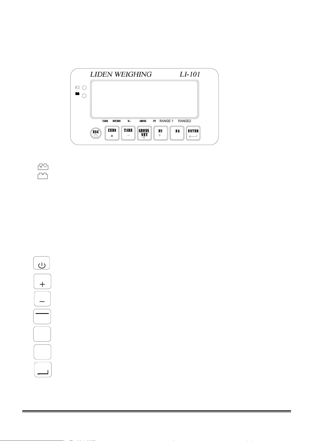
Chapter 3 Front and Rear Panels
3-1 Front Panel
Indication:
Keypad:
TARE
GR O SS
: Battery charged status (only available to charged model)
: Battery charging status (only available to charged model)
TARE : Tare status
MOTION : Unstable weighing indication
M+ : Accumulation status indication
GROSS : Gross weight
PT : Pre-tare
RANGE1 : Dual-range resolution inducation (1)
RANGE2 : Dual-range resolution inducation (2)
E SC
1) Power ON / OFF. Press and hold this key for 3 seconds to shut down.
2) To abort or exit when setting.
ZERO
1) Weight re-zero.
2) To add the value when setting.
1) To eliminate the gross weight.
2) To reduce the value when setting.
N ET
1) To switch Gross / Net weight shown on display.
2) To move the cursor leftward when setting.
F2
1) Keypad function (FNC-02 & FNC-03).
2) To move the cursor rightward when setting.
F1
Keypad function (FNC-02 & FNC-03).
ENTER
Confirmation key.
6
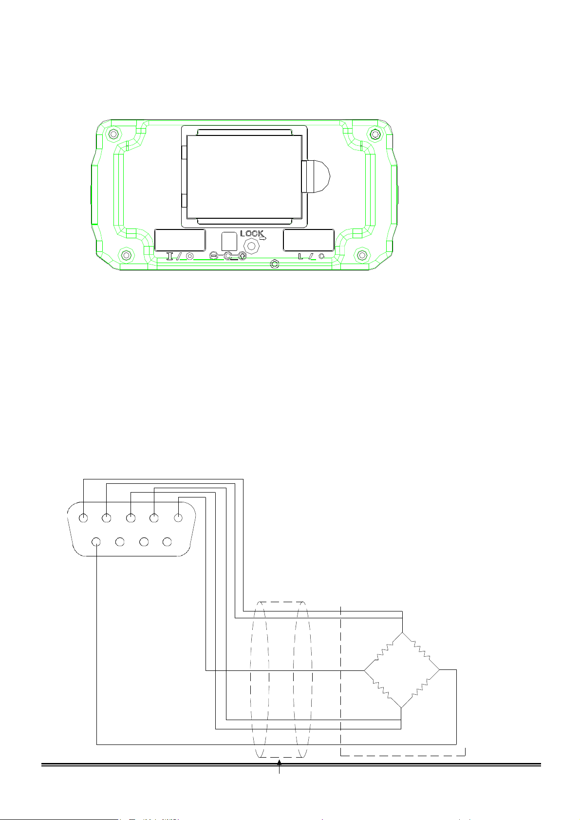
2
3
4
5 1
5 4 3 2 1
9 8 7 6
Load cell cable
EXC+
SEN+
SIG+ SIG-
EXC-
SEN-
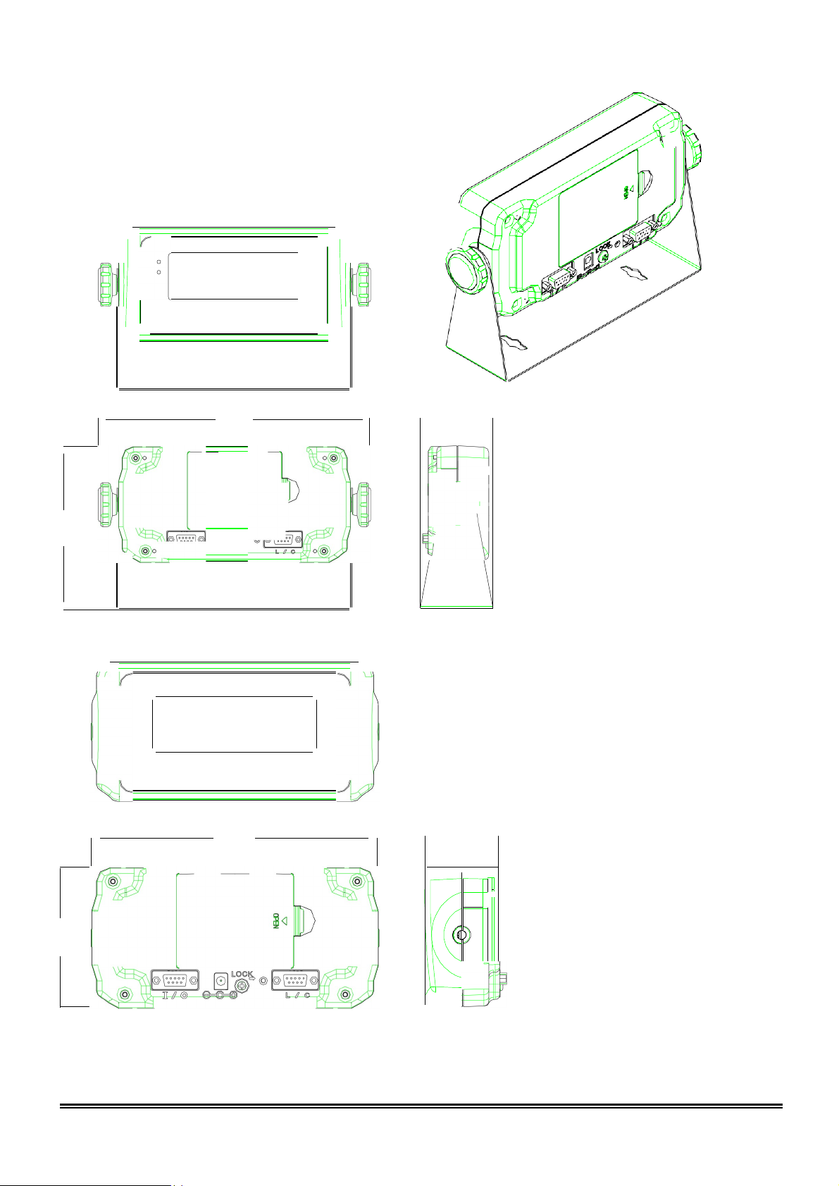
3-2 Rear Panel
1.
Battery Case
2.
RS232/485 Input/Output
3.
DC 9V Power Input
4.
Calibration Switch
5.
Load Cell Connect Socket
Chapter 4 Installation
4-1 Load Cell
Load cell

7
Shield
4-wired (5-wired) Load Cell
Pin 4, 5 short to connect with EXC+
Pin 2, 3 short to connect with EXCPin 1 connects with SIG+
Pin 9 connects with SIGPin 6, 7, 8 connects with Shield
6-wired (7-wired) Load Cell
Pin5 connects with EXC+
Pin4 connects with SEN+
Pin3 connects with EXCPin2 connects with SENPin1 connects with SIG+
Pin9 connects with SIGPin6, 7, 8 connect with Shield
8
225.0
<1
I
IT1-,;,:
:
:
:,::;;...JB
...
'-
"-=---
------6
0'
0-------
193.0
49 . 5----
:J
0
0
1 -
(
4-2 Dimension
9
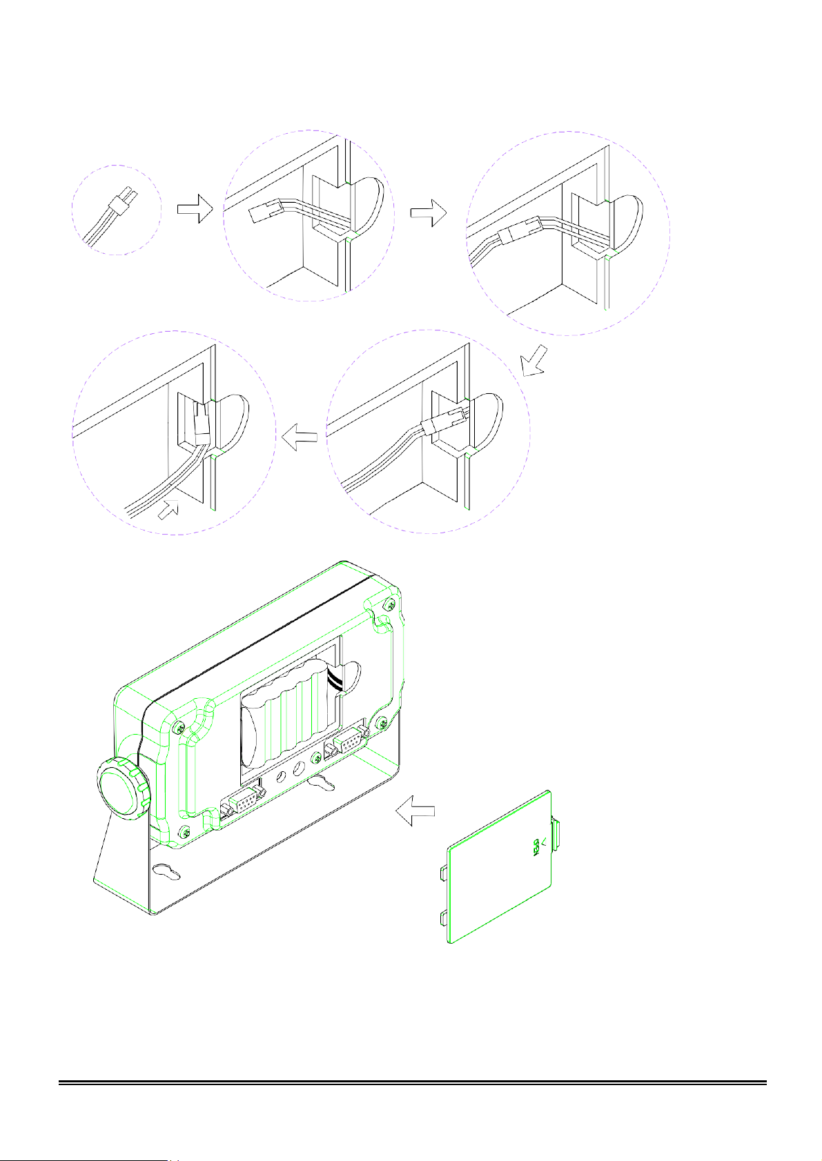
將多餘的電線塞入電池孔中
4-3 Battery Assemble
Stuff the surplus wires into the battery case.
10
ENTER
ENTER
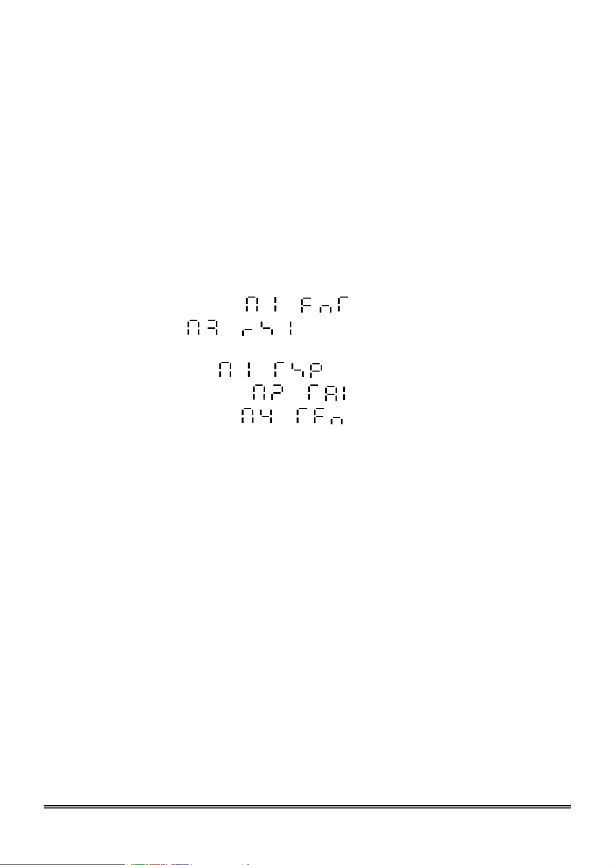
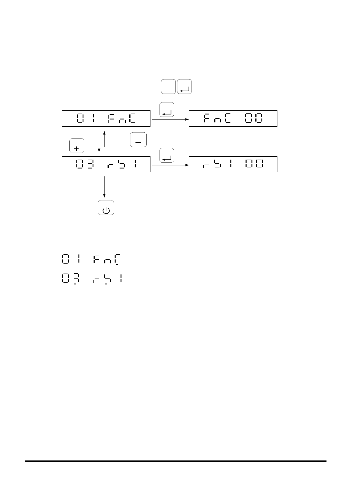
Chapter 5 External Function Parameter Setting
F1
Under general weight display status, press , and the screen will display:
Press key
ZERO
Press
TARE
key
ENTER
Press
ESC
to escape.
Back to general weight display status.
External function setting
RS232/RS485 interface function
 Loading...