

Licht MFC-400/I-IAC, MFC-400/I-IDC Technical Manual
Current Indicator/Transducer
mo del MFC-400/I-IAC and I-IDC
Technical Manual
Licht

Contents
1 Introduction 2
2 Front panel indication 3
3 Configuration 4
3.1 Parameter reset 4
4 Programmable parameters 5
4.1 General parameters 5
4.2 Current outputs (option) 5
4.3 MODBUS protocol 5
4.4 DNP3 protocol (option) 6
4.5 Language 7
A Specifications 8
B Connection diagrams 9
C MODBUS registers 13
Rev. A1 (20–05–09) MFC-400/I-IAC and I-IDC Technical Manual 1
http://www.licht-labs.com
Licht
info@licht-labs.com
1 Introduction
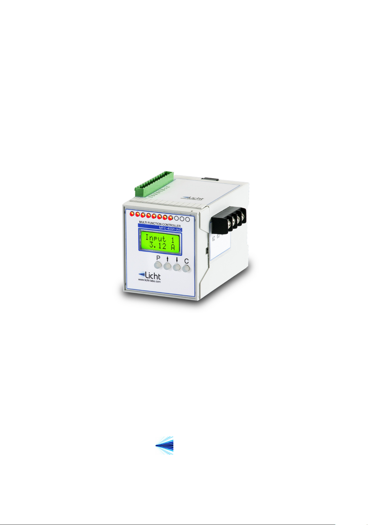
The MFC-400/I-IAC and MFC-400/I-IDC are precise, highly reliable and versatile mi-
crocontrolled devices designed to read, display and retransmit AC or DC current values.
They feature one isolated RS-485 port, which can be used for communication using the
MODBUS or DNP3 protocols.
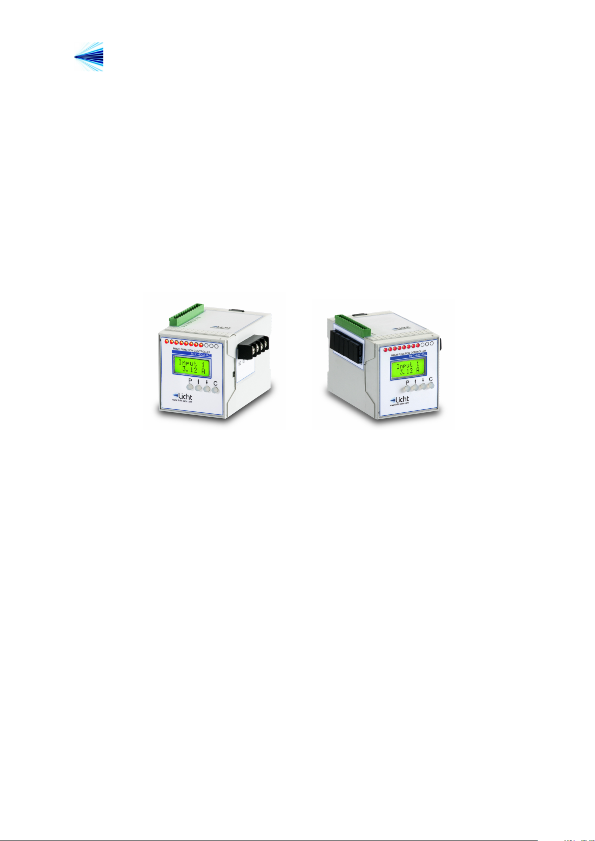
Signals that enter and exit the indicator are galvanically isolated, preventing potentially
damaging noise and transients from being transferred between subcircuits or retransmitted
to other devices.
Figure 1.1 MFC-400/I-IAC and MFC-400/I-IDC Indicators
Rev. A1 (20–05–09) MFC-400/I-IAC and I-IDC Technical Manual 2
http://www.licht-labs.com
C
P
R1 R2
R3
R4
R5
R6
R7
R8
R9
R10
R11
MFC-400/I-IAC
MULTI FUNCTION CONTROLLER
Licht
www.licht-labs.com
R12 R13
Input 1
3.12 A
Licht
info@licht-labs.com
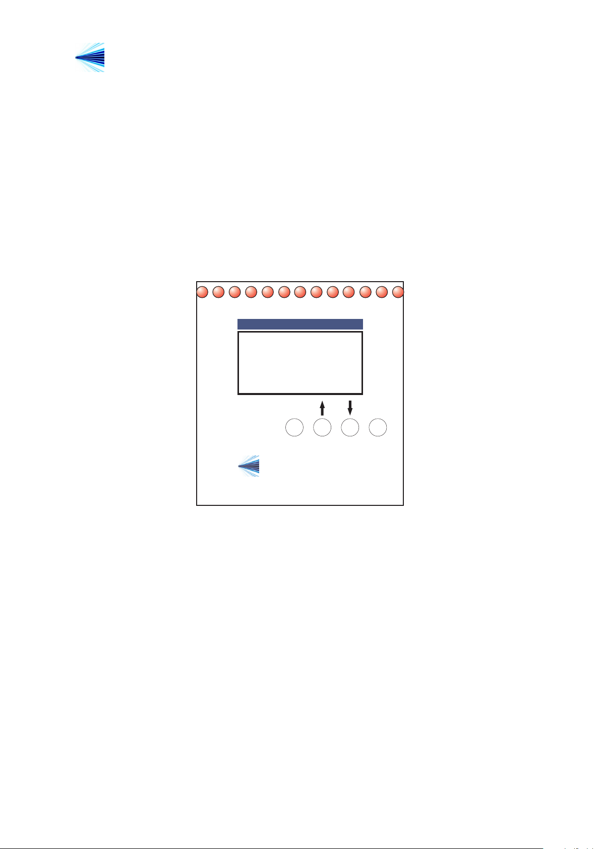
2 Front panel indication
During operation, the MFC-400/I-IAC and MFC-400/I-IDC alternate between each in-
put’s current indication. The presented value is equal to the measured current multiplied
by the Sampling Factor parameter.
If more than 2 inputs are used, a timer automatically changes the channels on display.
The user may manually alter the currently displayed channel (skipping the alternation
timer) by pressing the ↑ or ↓ keys.
Figure 2.1 Front Panel
Rev. A1 (20–05–09) MFC-400/I-IAC and I-IDC Technical Manual 3

http://www.licht-labs.com
Licht
info@licht-labs.com
3 Configuration
Parameterization
The MFC-400/I-IAC and MFC-400/I-IDC feature 4 keys to access their functions. The
procedure to configure any parameter is as follows:
1. Press the P key to enter the parameters menu.
2. Enter the currently configured 4 letter password one letter at a time, using the ↑
and ↓ keys to select each letter and P to advance between letters. The default
password is AAAA.
3. Using the ↑ and ↓ keys, choose the desired parameter.
4. Press P to confirm the parameter’s selection.
5. Choose the desired value with the ↑ and ↓ keys.
6. Confirm pressing P.
By holding down the ↑ or ↓ keys it is possible to advance through the options faster.
The configuration sequence can be cancelled at any time by pressing C.
3.1 Parameter reset
The MFC-400/I-IAC and MFC-400/I-IDC can be reset to factory settings. This procedure
also resets its password to AAAA. To do so, power up the device while pressing C.
Rev. A1 (20–05–09) MFC-400/I-IAC and I-IDC Technical Manual 4
 Loading...