

Licht MFC-202/P Technical Manual
Parallelism Controller
model MFC-202/P
Technical Manual
Licht

Contents
1 Introduction . . . . . . . . . . . . . . . . . . . . . . . . . . . . . . . . . . . . . . . . . . . . . . . . . . . . . . . . . . . 2
2 Operating principle . . . . . . . . . . . . . . . . . . . . . . . . . . . . . . . . . . . . . . . . . . . . . . . . . . . . 3
3 Operation . . . . . . . . . . . . . . . . . . . . . . . . . . . . . . . . . . . . . . . . . . . . . . . . . . . . . . . . . . . . . 5
3.1 Front panel indication . . . . . . . . . . . . . . . . . . . . . . . . . . . . . . . . . . . . . . . . . . . . . . . . 5
3.2 Manual commands . . . . . . . . . . . . . . . . . . . . . . . . . . . . . . . . . . . . . . . . . . . . . . . . . . . 5
3.3 Configuration . . . . . . . . . . . . . . . . . . . . . . . . . . . . . . . . . . . . . . . . . . . . . . . . . . . . . . . 6
3.4 Parameter reset . . . . . . . . . . . . . . . . . . . . . . . . . . . . . . . . . . . . . . . . . . . . . . . . . . . . . . 6
4 Programmable parameters . . . . . . . . . . . . . . . . . . . . . . . . . . . . . . . . . . . . . . . . . . . . . . 7
4.1 MODBUS protocol . . . . . . . . . . . . . . . . . . . . . . . . . . . . . . . . . . . . . . . . . . . . . . . . . . . 8
4.2 DNP3 protocol (option) . . . . . . . . . . . . . . . . . . . . . . . . . . . . . . . . . . . . . . . . . . . . . . . 9
5 Error conditions . . . . . . . . . . . . . . . . . . . . . . . . . . . . . . . . . . . . . . . . . . . . . . . . . . . . . . 11
5.1 Synchronism error . . . . . . . . . . . . . . . . . . . . . . . . . . . . . . . . . . . . . . . . . . . . . . . . . . 11
5.2 Position deviation . . . . . . . . . . . . . . . . . . . . . . . . . . . . . . . . . . . . . . . . . . . . . . . . . . . 11
5.3 Configuration error . . . . . . . . . . . . . . . . . . . . . . . . . . . . . . . . . . . . . . . . . . . . . . . . . . 11
5.4 Communication error . . . . . . . . . . . . . . . . . . . . . . . . . . . . . . . . . . . . . . . . . . . . . . . . 12
A Specifications . . . . . . . . . . . . . . . . . . . . . . . . . . . . . . . . . . . . . . . . . . . . . . . . . . . . . . . . . 13
B Housing . . . . . . . . . . . . . . . . . . . . . . . . . . . . . . . . . . . . . . . . . . . . . . . . . . . . . . . . . . . . . 14
C Connection diagrams . . . . . . . . . . . . . . . . . . . . . . . . . . . . . . . . . . . . . . . . . . . . . . . . . . 15
D Configuration sheet . . . . . . . . . . . . . . . . . . . . . . . . . . . . . . . . . . . . . . . . . . . . . . . . . . . 18
E MODBUS registers . . . . . . . . . . . . . . . . . . . . . . . . . . . . . . . . . . . . . . . . . . . . . . . . . . . . 19
Rev. A2 (30–05–12) MFC-202/P Technical Manual 1

http://www.licht-labs.com
Licht
info@licht-labs.com
1 Introduction
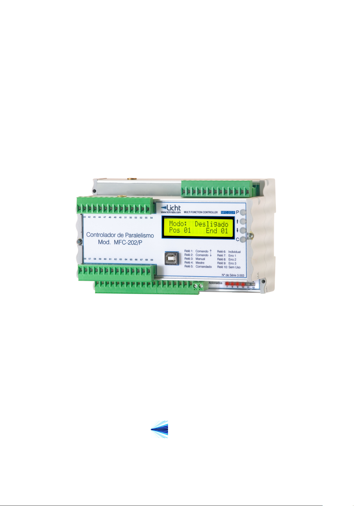
The MFC-202/P controller was developed by Licht for the paralellism supervision and
control of 3-phase power transformers and 3-phase groups of monophase transformers.
The MFC-202/P features 10 relays for electromechanic logic, one RS485 interface for
supervision and control and one optional current output for position retransmission.
The parallelism control is implemented according to the master-follower principle, under
which all tap changer positions are kept synchronized. For parallel control to be success-
ful under this scenario, we admit that all involved transformers have identical nominal
currents, number of taps and voltage delta per tap. Each tap changer’s position is read
directly from its potentiometric sensor or indirectly either via a current loop (typically 4-
20 mA) or BCD contacts, according to the client’s specifications. During parallel control,
the Master tap changer’s position is compared to its Followers’, and tap changer pulses
are issued to the Follower tap changers whose positions don’t match their Master’s.
In the MFC-202/P architecture, each controller is responsible for a 3-phase transformer
or a monophase transformer, and is interconnected with other MFC-202/P using a RS485
bus arrangement. MODBUS or DNP3 functionality is provided on a second dedicated
RS485 port, which does not require additional hardware.
Figure 1.1 MFC-202/P controller
Rev. A2 (30–05–12) MFC-202/P Technical Manual 2

http://www.licht-labs.com
Licht
info@licht-labs.com
2 Operating principle
General Case
The operation of transformers in parallel can be motivated by expansion, redundancy or
convenience. For it to be practical, the transformers involved must have their secondary
voltages as similar as possible at all times. Otherwise, transformers with lower outputs
become loads to the others, creating circulation currents.
The MFC-202/P is designed for power transformers with on-load tap changers. These
can adjust their tranformation relation as their loads change, guaranteeing adequate reg-
ulation. The Master-Follower principle supposes that the involved transformers have tap
changers with the same number of taps, and that each tap corresponds to the same out-
put voltage. Circulation currents are minimized by operating transformers on identical
positions.
In the Master-Follower principle, a transformer which we denote the Master is chosen as
the reference. The others, denoted Followers, have their positions automatically updated
in order to match the Master. Parallel control is synchronous, because all transformers –
irrespective of being the Master or the Follower – receive simultaneous commands. Trans-
formers can be removed from parallel control if configured as Individual, and completely
ignored if configured as Disabled.
Some exceptional scenarios are detected and treated. These can vary from tap changer
failures (for example, when a Follower transformer doesn’t respond to commands and fails
to match its Master) to configuration errors (for example, configuring a Master without
Followers or Followers without a Master).
Master
Transformer
Position 9
Figure 2.1 3-phase Transformer Parallelism
Rev. A2 (30–05–12) MFC-202/P Technical Manual 3
Follower
Transformer
Position 9
Individual
Transformer
Position 5

http://www.licht-labs.com
Licht
Manual Commands
Transformers configured as Master or Individual can be manually commanded by an
operator. This command may be local (issued on the controller’s keyboard) or remote
(with digital dry contact inputs).
If a Follower transformer fails to respond to tap change commands, the MFC-202/P will
ignore subsequent commands and signal the error condition. In this scenario, the oper-
ator must reconfigure the transformer as Individual and manually manage the system’s
parallelism until a solution can be found.
info@licht-labs.com
Rev. A2 (30–05–12) MFC-202/P Technical Manual 4
http://www.licht-labs.com
C
P
MULTI FUNCTION CONTROLLER
MFC-202/P
Licht
www.licht-labs.com
Parallelism Controller
Mod. MFC-202/P
Relay 1: Relay 6: Individual
Relay 2: ¯ Command Relay 7: Error 1
Relay 3: Manual
Relay 8: Error 2
Relay 4: Master
Relay 9: Error 3
Relay 5: Follower
Relay 10: Unused
Command
Mode: Individual
Pos 01 Addr 00
43 42 45 44 47 46 49 48 51 50 53 52 55 54
56 57 58 59 60 61 62 63 64 65 66 67 68 69
Licht
info@licht-labs.com
3 Operation
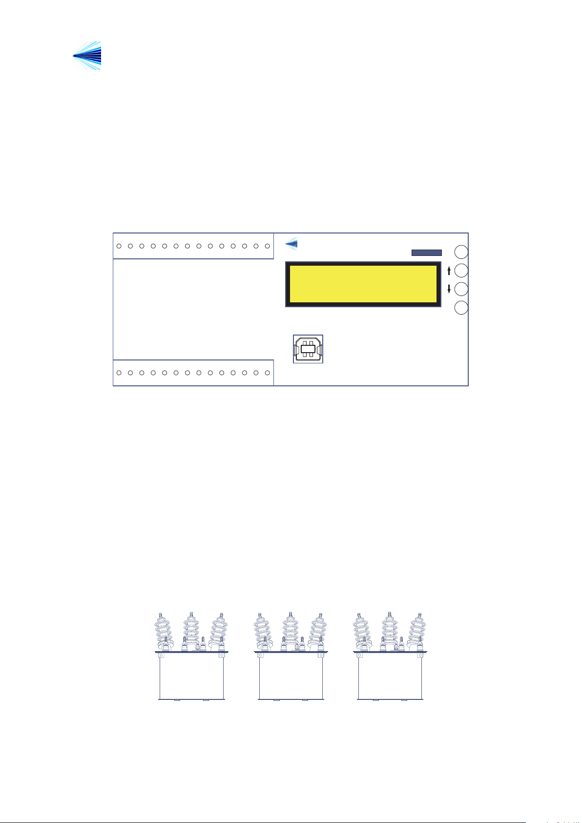
3.1 Front panel indication
Under normal operation, the MFC-202/P indicates its channel’s position, operation mode
(Master, Follower, Individual, Disabled) and, if applicable, the raise (↑) or lower (↓)
command indications. Figure 3.1 presents a front panel indication example.
In alarm situations, the display alternates between an error message and the channel’s
indication, regardless of the device’s configuration.
3.2 Manual commands
Transformers configured as Master or Individual can be directly commanded by the MFC-
202/P with a manual command. Whenever the transformer is configured as Follower or
Disabled, the command is ignored. Manual commands are only accepted if there’s no
synchronism error between all tap changers.
To perform a manual command, press P, choose the “Manual Command” option, press
P again to confirm and then issue a raise or lower command with the ↑ or ↓ key.
Rev. A2 (30–05–12) MFC-202/P Technical Manual 5
Figure 3.1 Front Panel
Master
Transformer
↑ Position 7 ↑
Figure 3.2 Raise Command Example (Before)
Follower
Transformer
Position 7
Individual
Transformer
Position 4

Licht
http://www.licht-labs.com
info@licht-labs.com
Master
Transformer
Position 8
Figure 3.3 Raise Command Example (After)
Follower
Transformer
Position 8
Follower
Transformer
Position 4
3.3 Configuration
The MFC-202/P features 4 keys to access its functions. The procedure to configure any
parameter is as follows:
1. Press the P key to enter the parameters menu.
2. Using the ↑ and ↓ keys, choose the desired parameter.
3. Press P to confirm the parameter’s selection.
4. Choose the desired value with the ↑ and ↓ keys.
5. Confirm pressing P.
The configuration sequence can be cancelled at any time by pressing C.
3.4 Parameter reset
The MFC-202/P can be reset to factory settings. This procedure also resets its password
to AAAA. To do so, power on the device while pressing C.
Rev. A2 (30–05–12) MFC-202/P Technical Manual 6
 Loading...