

Licht MFC-200/P Technical Manual
Parallelism Controller
model MFC-200/P
Technical Manual
Licht

Contents
1 Introduction . . . . . . . . . . . . . . . . . . . . . . . . . . . . . . . . . . . . . . . . . . . . . . . . . . . . . . . . . . . 2
2 Available versions . . . . . . . . . . . . . . . . . . . . . . . . . . . . . . . . . . . . . . . . . . . . . . . . . . . . . . 3
3 Operating principle . . . . . . . . . . . . . . . . . . . . . . . . . . . . . . . . . . . . . . . . . . . . . . . . . . . . 4
4 Operation . . . . . . . . . . . . . . . . . . . . . . . . . . . . . . . . . . . . . . . . . . . . . . . . . . . . . . . . . . . . . 6
4.1 Front panel indication . . . . . . . . . . . . . . . . . . . . . . . . . . . . . . . . . . . . . . . . . . . . . . . . 6
4.2 Manual commands . . . . . . . . . . . . . . . . . . . . . . . . . . . . . . . . . . . . . . . . . . . . . . . . . . . 6
4.3 Configuration . . . . . . . . . . . . . . . . . . . . . . . . . . . . . . . . . . . . . . . . . . . . . . . . . . . . . . . 7
4.4 Calibration . . . . . . . . . . . . . . . . . . . . . . . . . . . . . . . . . . . . . . . . . . . . . . . . . . . . . . . . . . 8
4.5 Parameter reset . . . . . . . . . . . . . . . . . . . . . . . . . . . . . . . . . . . . . . . . . . . . . . . . . . . . . . 8
5 Programmable parameters . . . . . . . . . . . . . . . . . . . . . . . . . . . . . . . . . . . . . . . . . . . . . . 9
5.1 MODBUS protocol . . . . . . . . . . . . . . . . . . . . . . . . . . . . . . . . . . . . . . . . . . . . . . . . . . 10
5.2 DNP3 protocol (option) . . . . . . . . . . . . . . . . . . . . . . . . . . . . . . . . . . . . . . . . . . . . . . 11
6 Error conditions . . . . . . . . . . . . . . . . . . . . . . . . . . . . . . . . . . . . . . . . . . . . . . . . . . . . . . 13
6.1 Synchronism error . . . . . . . . . . . . . . . . . . . . . . . . . . . . . . . . . . . . . . . . . . . . . . . . . . 13
6.2 Position deviation . . . . . . . . . . . . . . . . . . . . . . . . . . . . . . . . . . . . . . . . . . . . . . . . . . . 13
6.3 Configuration error . . . . . . . . . . . . . . . . . . . . . . . . . . . . . . . . . . . . . . . . . . . . . . . . . . 13
6.4 Communication error . . . . . . . . . . . . . . . . . . . . . . . . . . . . . . . . . . . . . . . . . . . . . . . . 14
A Specifications . . . . . . . . . . . . . . . . . . . . . . . . . . . . . . . . . . . . . . . . . . . . . . . . . . . . . . . . . 15
B Housing . . . . . . . . . . . . . . . . . . . . . . . . . . . . . . . . . . . . . . . . . . . . . . . . . . . . . . . . . . . . . 16
C Connection diagrams . . . . . . . . . . . . . . . . . . . . . . . . . . . . . . . . . . . . . . . . . . . . . . . . . . 17
D Configuration sheet (MFC-200/P/1 and MFC-200/P/b) . . . . . . . . . . . . . 23
E Configuration sheet (MFC-200/P/2) . . . . . . . . . . . . . . . . . . . . . . . . . . . . . . . . . . 24
F MODBUS registers (MFC-200/P/2) . . . . . . . . . . . . . . . . . . . . . . . . . . . . . . . . . . 25
G MODBUS registers (MFC-200/P/b) . . . . . . . . . . . . . . . . . . . . . . . . . . . . . . . . . . 26
Rev. A2 (23–01–09) MFC-200/P Technical Manual 1

http://www.licht-labs.com
Licht
info@licht-labs.com
1 Introduction
The MFC-200/P controller was developed by Licht for the paralellism supervision and
control of 3-phase power transformers and 3-phase groups of monophase transformers.
The MFC-200/P can feature up to 6 current loop outputs for position retransmission,
14 relays for electromechanic logic and an RS485 interface for supervision and remote
control.
The parallelism control is implemented according to the master-follower principle, under
which all tap changer positions are kept synchronized. For parallel control to be success-
ful under this scenario, we admit that all involved transformers have identical nominal
currents, number of taps and voltage delta per tap. Each tap changer’s position is read
directly from its potentiometric sensor or indirectly either via a current loop (typically 4-
20 mA) or BCD contacts, according to the client’s specifications. During parallel control,
the Master tap changer’s position is compared to its Followers’, and tap changer pulses
are issued to the Follower tap changers whose positions don’t match their Master’s.
In the MFC-200/P architecture, each controller is responsible for a 3-phase transformer
or 3-phase group of monophase transformers. There’s a 3-phase Group ↔ 3-phase Trans-
former equivalence, such that all instructions contained in this manual apply to both
configurations.
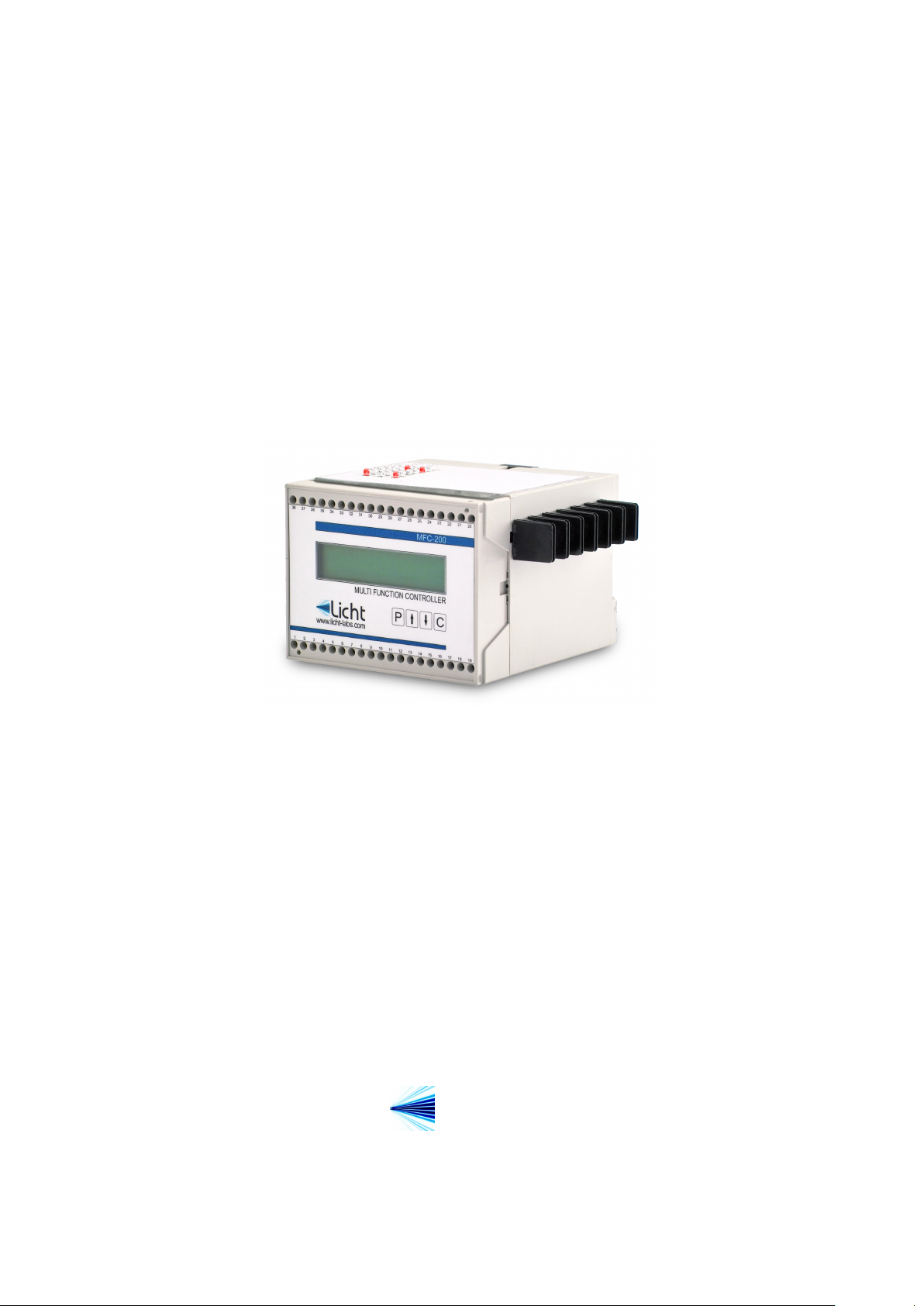
The MFC-200/P shares its form factor with other Licht controllers for transformers, such
as the MFC-200/R voltage regulator and the MFC-200/T temperature controller. All
signals that enter and exit the controller are pairwise galvanically isolated, preventing
potentially damaging noise and transients from being transferred between subcircuits or
retransmitted to other devices.
Figure 1.1 Controlador MFC-200/P
Rev. A2 (23–01–09) MFC-200/P Technical Manual 2

http://www.licht-labs.com
Licht
info@licht-labs.com
2 Available versions
To better suit the market’s diversity, the MFC-200/P parallelism controller is available
in 3 versions:
1. MFC-200/P/1: controls one 3-phase transformer, possibly networked with other
MFC-200/P/1 and MFC-200/P/b devices.
2. MFC-200/P/2: controls a pair of 3-phase transformers, without network option.
3. MFC-200/P/b: controls a 3-phase bank of monophase transformers, possibly net-
worked with other MFC-200/P/1 or MFC-200/P/b devices.
Communication functionality with supervisor systems is available in all versions, does not
require additional hardware and does not depend on MFC-200/P network connectivity.
All MFC-200/P controllers have the same hardware specifications and software parame-
ters. All devices are equally customizable in order to suit special configurations (for
example, concerning position acquisition, remote transmission and communication proto-
cols).
Rev. A2 (23–01–09) MFC-200/P Technical Manual 3

http://www.licht-labs.com
Licht
info@licht-labs.com
3 Operating principle
General Case
The operation of transformers in parallel can be motivated by expansion, redundancy or
convenience. For it to be practical, the transformers involved must have their secondary
voltages as similar as possible at all times. Otherwise, transformers with lower outputs
become loads to the others, creating circulation currents.
The MFC-200/P is designed for power transformers with on-load tap changers. These
can adjust their tranformation relation as their loads change, guaranteeing adequate reg-
ulation. The Master-Follower principle supposes that the involved transformers have tap
changers with the same number of taps, and that each tap corresponds to the same out-
put voltage. Circulation currents are minimized by operating transformers on identical
positions.
In the Master-Follower principle, a transformer which we denote the Master is chosen as
the reference. The others, denoted Followers, have their positions automatically updated
in order to match the Master. Parallel control is synchronous, because all transformers –
irrespective of being the Master or the Follower – receive simultaneous commands. Trans-
formers can be removed from parallel control if configured as Individual, and completely
ignored if configured as Disabled.
Some exceptional scenarios are detected and treated. These can vary from tap changer
failures (for example, when a Follower transformer doesn’t respond to commands and fails
to match its Master) to configuration errors (for example, configuring a Master without
Followers or Followers without a Master).
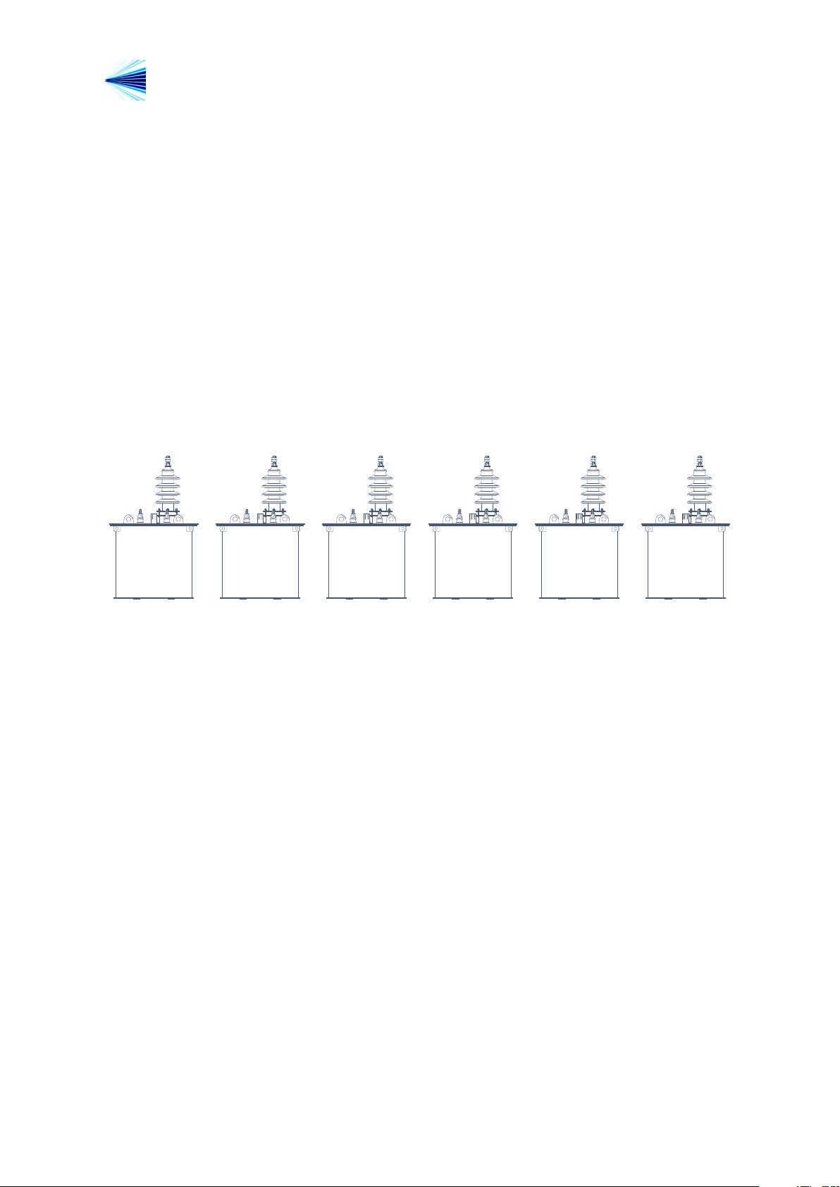
Master
Transformer
Position 9
Figure 3.1 3-phase Transformer Parallelism
Rev. A2 (23–01–09) MFC-200/P Technical Manual 4
Follower
Transformer
Position 9
Individual
Transformer
Position 5
http://www.licht-labs.com
Licht
info@licht-labs.com
3-phase Groups of Monophase Transformers
3-phase groups of monophase transformers are a special case of parallelism. Each group is
formed by 3 monophase transformers and their respective on-load tap changers. From an
external perspective, a group must behave as a 3-phase transformer. Therefore, each of
its phases must present the same secondary voltage. This is satisfied if each phase’s tap
changer is on the same position. For groups to be mutually synchronized, tap changers
from different groups must also be in numerically equal positions.
For the purposes of parallel operation, each group is classified as Master, Follower, In-
dividual or Disabled. The equivalence Group ↔ 3-phase Transformer is only lost when a
group is set as Disabled. Otherwise, the MFC-200/P will always attempt to maintain a
group’s 3 phases in the same numerical position.
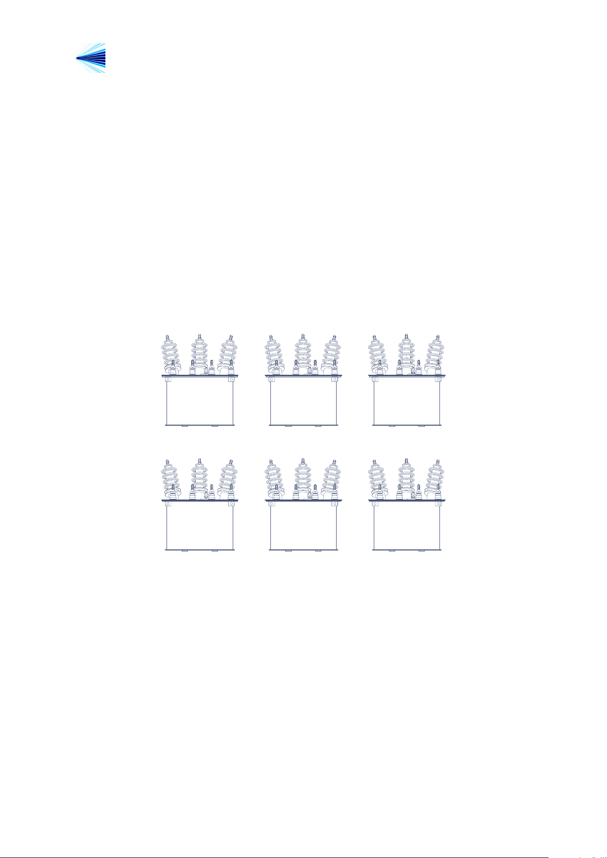
Master
Phase A
Position 9
Master
Phase B
Position 9
Master
Phase C
Position 9
Follower
Phase A
Position 9
Follower
Phase B
Position 9
Follower
Phase C
Position 9
Figure 3.2 3-phase Group Paralellism
Manual Commands
Transformers or groups configured as Master or Individual can be manually commanded
by an operator. This command may be local (issued on the controller’s keyboard) or
remote (via the RS485 interface). In the case of groups, the command is repeated on all
3 phases.
If a Follower transformer fails to respond to tap change commands, the MFC-200/P will
ignore subsequent commands and signal the error condition. In this scenario an oper-
ator must reconfigure the transformer as Individual and manually manage the system’s
parallelism until a solution can be found.
Rev. A2 (23–01–09) MFC-200/P Technical Manual 5

http://www.licht-labs.com
CP
Licht
www.licht-labs.com
PARALLELISM CONTROLLER
MFC-200/P/1
1 2 345 6 7 8 9 10 11 12 13 14 15 16 17 18 19
38 37 363534 33 32 31 30 292827 26 25 2423222120
Chan. 03 Pos. 07
Mode: Master
Licht
info@licht-labs.com
4 Operation
4.1 Front panel indication
Under normal opration, the MFC-200/P indicates its channel’s position, operation mode
(Master, Follower, Individual, Disabled) and, if applicable, the raise (↑) or lower (↓)
command indications. Figure 4.1 presents a front panel indication example.
Figure 4.1 Front Panel
3-phase transformer channels are indicated by their number. Group channels are indicated
by their number and phase – for example, channel 2B corresponds to group 2’s B phase.
Phase A is always a bank’s reference phase which phases B and C automatically follow.
Whenever the MFC-200/P is configured for 3-phase transformers, the channel’s position
is always displayed. If configured for a bank of monophase transformers, the display
alternates each phase’s position. In alarm situations, the display alternates between an
error message and the channel’s indication, regardless of the device’s configuration.
4.2 Manual commands
3-phase transformers or 3-phase groups of monophase transformers configured as Mas-
ter or Individual can be directly commanded by the MFC-200/P with a manual com-
mand. Whenever the transformer or group is configured as Follower or Disabled, the
command is ignored. In the case of MFC-200/P/2 controllers, manual commands act on
the Master/Follower pair, simultaneously altering both transformers’ positions. Manual
commands are only accepted if there’s no synchronism error between all channels.
To perform a manual command, press the ↑ or ↓ key.
Rev. A2 (23–01–09) MFC-200/P Technical Manual 6
http://www.licht-labs.com
Licht
info@licht-labs.com
It is also possible to command a 3-phase group’s given phase. First verify that the channel
is configured as Disabled (if not, an error message will be displayed and the command
will be ignored). Next, press the P key and select Manual Command in the configuration
menu. Select the phase to be commanded (A, B or C) and press P. The command is
given with the ↑ or ↓ key. This sequence can be cancelled at any moment by pressing the
C key.
It is also possible to manually command a given transformer controlled by an MFC-
200/P/2. First verify that the channel to be commanded is configured as Individual (if
not, an error messsage will be displayed and the command will be ignored). Next, press
the P key and select Manual Command in the configuration menu. Select the transformer
to be commanded (1 or 2) and press P. The command is given with the ↑ or ↓ key. This
sequence can be cancelled at any moment by pressing the C key.
Master
Transformer
↑ Position 7 ↑
Follower
Transformer
Position 7
Individual
Transformer
Position 4
Figure 4.2 Raise Command Example (Before)
Master
Transformer
Position 8
Follower
Transformer
Position 8
Follower
Transformer
Position 4
Figure 4.3 Raise Command Example (After)
4.3 Configuration
The MFC-200/P features 4 keys to access its functions. The procedure to configure any
parameter is as follows:
1. Press the P key to enter the parameters menu.
2. Using the ↑ and ↓ keys, choose the desired parameter.
3. Press P to confirm the parameter’s selection.
4. Choose the desired value with the ↑ and ↓ keys.
5. Confirm pressing P.
Rev. A2 (23–01–09) MFC-200/P Technical Manual 7

http://www.licht-labs.com
Licht
The configuration sequence can be cancelled at any time by pressing C.
info@licht-labs.com
4.4 Calibration
Before commissioning, the MFC-200/P must be calibrated for the tap changer’s poten-
tiometric disc. The procedure to do so follows:
1. Power on the device while pressing ↑ or ↓.
2. The message Min. Tap A Phase will be displayed along with a value proportional
to phase A’s measured resistance. Take the tap changer to its minimal position.
When the value stabilizes, press the P key.
3. The message Max. Tap A Phase will be displayed along with a value proportional
to phase A’s measured resistance. Take the tap changer to its maximum position.
When the value stabilizes, press the P key.
4. Repeat the procedure for phases B and C.
This calibration guarantees precise measurements, regardless of connection length or cross-
section. We recommend this procedure is repeated every time the sensor interconnections
are altered significantly.
4.5 Parameter reset
The MFC-200/P can be reset to factory settings. This procedure also resets its password
to AAAA. To do so, power on the device while pressing C.
Rev. A2 (23–01–09) MFC-200/P Technical Manual 8
 Loading...