


Libre Home
Dimmer&Relay Control
User’s Manual

Cautions and Warnings
Knowning Dimmer
Knowning Relay Control
Getting Started
Install ation St eps
Install ation
Installation Wiring Diagrams
Joining Network
Troubleshooting
Contents

Cautions and Warnings
Read and understa nd these i nstruc tions be fore ins talling and retain them for future refere nce.
This pr oduc t is int ende d for in stal lati on in ac cord ance w ith th e Nati onal E lect ric Co de and l ocal r egul atio ns in
the Uni ted St ates o r the Ca nadi an Ele ctri cal Co de and l ocal r egul atio ns in Ca nada . Use in door s only. Thi s
product is no t desi gned o r appr oved f or use o n powe r line s othe r than 1 20V 60 Hz, si ngle p hase . Attem ptin g to
use thi s prod uct on n on-a ppro ved po wer li nes ma y have h azar dous c onse quen ces.
Recommended installat ion prac tices:
- Use only indoors in dry locatio n.
- Be sure that yo u have t urne d off the c ircu it bre aker o r remo ved th e fuse f or the c ircu it you a re ins tall ing
this pr oduc t into . Inst alli ng thi s prod uct wi th the p ower o n will e xpos e you to d ange rous v olta ges.
- Connect usi ng onl y copp er or co pper -cla d wire .
- This pr oduc t may fe el war m duri ng ope rati on. The amo unt of h eat ge nera ted is w ithi n appr oved l imit s
and pos es no ha zard s. To minimize heat build up, en sure t he are a surr ound ing th e rear o f this p rodu ct is
as clea r of clu tter a s poss ible .
- To reduce the risk of ove rhea ting a nd pos sibl e dama ge to ot her eq uipm ent, d o not us e this p rodu ct to
contr ol loa ds in ex cess o f the sp ecifi ed max imum (s) or, i nsta ll in lo cati ons wi th ele ctri city s peci ficat ions
which a re out side o f the pr oduc t’s s peci ficat ions .
Identif ying the E lectri cal Wires in Your Home:
- line – carries 120VAC electri city i nto th e wall b ox, ma y also b e call ed hot , live o r powe r, comm only b lack
- neutr al – ret urns 1 20VAC to pow er com pany, comm only w hite a nd in a mu lti- wire b undl e
- load – co nnec ts to li ght/ load d evic e, com monl y blac k and in a s epar ate ca ble ja cket
- ground – connecti on to el ectr ical g roun d, com monl y a bare w ire, a g reen w ire or a s crew o n a meta l box
IMPORTANT:
If you have a ny difficu lties or q uestions, consult an electrician. If you are not kn owledg eable ab out
and comfo rtable w ith elec trical c ircuitry, hav e a qualifi ed elect rician i nstall the product for you.
WARNING:
Changes or modific ations t o this dev ice not expressly approved by the party responsible for
compliance coul d void the u ser ’s authority to operate the equipment.
Caution:
To Reduce the Risk of Ove rheati ng And Poss ible Dam age to Oth er Equipment,
Do Not Inst all To Control A Recepta cle, A Motor-Operated Appliance, A
Fluores cent Lig hting Fi xture, Or A Transformer-Supplied Appliance;

Knowning Dimmer
LED Bar
Brightnes s Indi cato r
Dimmer
with sing le key
Safe ty Bu tto n
Back View
Grou ndi ng Le ad
Reset But ton
Neutral L ead
Loading Lead
Line Lead
Knowing Saf ety bu tton
Dimmer
with repl aceabl e keys
Grou ndi ng Le ad
Reset But ton
Neutral L ead
Loading Lead
Line Lead
Safe ty Bu tto n
Groun d
NEU
LOA D
Anyti me you n eed Di mmer 's con trol led ci rcui t to be un powe red bu t
don't want to t urn off t he cir cuit b reak er—s uch as w hen re plac ing
light bulbs —use t he Saf ety bu tton t o quic kly an d conv enie ntly
disable power.
Using your fin gern ail or a s mall fl athe ad scr ewdr iver, p ull ou t Safe ty
butto n. Th is ope ns the m echa nica l cont acts a nd rem oves a ll pow er
from Di mmer a nd its l oad. ( Beca use Di mmer 's set ting s are st ored i n
its non -vol atil e memo ry, yo ur set up inf orma tion w ill no t be los t.)
To re-enable power to Dimmer, simply push in the S afet y butt on unt il
it is flus h with t he tri m fram e.
LIN E

Knowning Relay Control
LED Bar
Brightnes s Indi cato r
Relay Con trol
with sing le key
Grou ndi ng Le ad
Reset But ton
Neutral L ead
Loading Lead
Line Lead
Back View
Groun d
Relay Con trol
with repl aceabl e keys
Grou ndi ng Le ad
Reset But ton
Neutral L ead
Loading Lead
Line Lead
NEU
LOA D
LIN E

Installation Steps
Get Installation tools
Remove the old dimmer or relay control
Connect the dimmer or relay control
wires to the Junction box wires
Install the Dimmer or Relay Control
into the junction box
Test the Dimmer or Relay Control by tapping
the paddle to turn on and off

Installation
Read Instruction Before installation
Get installation Tools:
Disconnect Power
Turn off powe r to your di mmer or
switch at t he elect rical se rvice pa nel
Always disconnect
power before installation.
Reconnect Power
Remove the old Dimmer or Switch
Remove th e old dimm er and dis connec t the wire s.
If your box l acks neu tral wir es, stop and contact support.
Identify Line and Load

Installation
Wire-In the Dimmer or Relay Control
Turn off power at the c ircuit breaker. Connect the dimmer or relay control wires to t he ident ified wir es in the
junctio n box. Veri fy that th e wire nut s are secure and that no exposed copper wire is visible except for the
bare ground wire. Addition al wirin g diagra ms can be fo und in the I nstallation Diagrams section.
Grou ndi ng
NEU
LOAD
Install Dimmer or Relay Control
Mount the D immer or R elay Con trol int o
the junct ion box wi th the LED b ar on the
left
LINE
Tur n powe r on to th e Dimm er or Re lay
Contr ol at th e circ uit br eake r pane l.
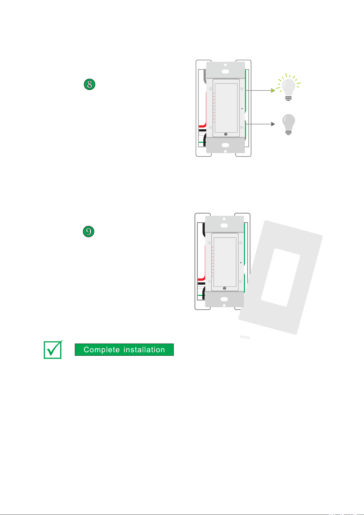
Test the Dimmer or Relay Contro l
Test your dimmer or rel ay con trol b y
tappi ng the p addl e to tur n On and O f.
For dim mer, Pr ess an d hold t o
dim or brighten.
Installation
Install w all plat e
Complete in stal lati on by re atta chin g
your wall plate. Fo r the be st loo k, use
an scre wles s wall p late

Installation Wiring Diagrams
Use the installation diagrams is this section to help you wire your
Dimmer and Relay Control

2-Way wiring diagram
Note: The wire colors indicated a re the reg ular
colors, may differ ent in som e homes.
Connection instructions:
Insulation strip length: 12mm
Splicing wire connector: For 16AWG wires, Max twisting numbers: 3
The dimmer is rated for use with Copper wire only
For supply connection, use wires rated at least 75℃
Grounding
NEU
LOAD
LINE

3-Way Wiring Diagram
Using Dimmer or Relay Control in Virtual Multi -Way Circuits
You can use Dimmer or Relay Control to replace switches in multi -way circuits that are already wired in or to
create multi-way circuits where there is no existing wiring. These are called virtual multi -way circuits. In a virtual
multi-way circuit, only one Dimmer or Relay Control is actually connected to and controls the load. Any
additional Dimmer or Relay Control modules (called Dimmer or Relay Control Secondaries) are only connected
to the powerline via the line and neutral wires. All Dimmer or Relay Con trol can communicate with one another
using Libre Home networking on the powerline. After wiring in Dimmer or Relay Control, you can create a virtual
multi-way circuit by setting up all of the modules to control each other. The diagram below shows how you
convert a wired-in 3-way circuit using two Dimmer or Relay Control.
Note: The wire colors indicated a re the reg ular
colors, may differ ent in som e homes.
Load
NEU
GROUND
LOAD
LINE
Incommi ng power
Trav eler
wires
Not Used
Trav eler
wires
Not Used
Inside wa ll cable
To Load
GROUND
LOAD
LINE
NEU
If your lig hting ci rcuit in cludes more than two Dimmer or Relay Controls contr olling a s ingle se t of light s,
those ext ra Dimme r or Relay C ontrol s will hav e four wires connected to them. Two of the wires are travelers
from the pr ecedin g Dimmer o r Relay Co ntrols , while the other two are travelers to the next D immer or R elay
Control s in the cha in. You will c onvert t he black t ravele r wires to line wires and replace the old 4-wire Dimmer
or Relay Controls .
See next pa ge for 4-Way Wiring Diagram
Special Treatment for 4- or More-Way Circuits

4-Way Wiring Diagram
Note: The wire colors indicated a re the reg ular
colors, may differ ent in som e homes.
Load
GROUND
NEU
LOAD
LINE
Incomming power
Trav eler
wires
Not Used
Trav eler
wires
Not Used
To Load
GROUND
LOAD
LINE
NEU
Tra veler w ires
Not Us ed
Ground
Tra veler w ires
Not Us ed
Trav eler wir es
Not Used
LINE
LOAD
NEU

In Libre Ho me mobil e App.
Navigate to Hub Con figurat ion scre en.
Press "Ad d New Devi ce”
Then foll ow the ins tructi on on screen.
Joining Network

Trouble Shooting
In Libre Ho me mobil e App.
Press "De vices”
Locate th e dimmer o r relay co ntrol that needs troubleshooting
Click "Troub leshoo ting”

FCC STATEMENT
1. This device complies with Part 15 of the FCC Rules. Operation is subject to the following two
conditions:
(1) This device may not cause harmful interference, and
(2) This device must accept any interference received, including interference that may cause
undesired operation.
2. Changes or modifications not expressly approved by the party responsible for compliance could
void the user’s authority to operate the equipment.
This equipment has been tested and found to comply with the limits for a Class B digital device,
pursuant to part 15 of the FCC Rules. These limits are designed to provide reasonable protection
against harmful interference in a residential installation. This equipment generates, uses and can
radiate radio frequency energy and, if not installed and used in accordance with the instructions,
may cause harmful interference to radio communications. However, there is no guarantee that
interference will not occur in a particular installation. If this equipment does cause harmful
interference to radio or television reception, which can be determined by turning the equipment off
and on, the user is encouraged to try to correct the interference by one or more of the following
measures:
—Reorient or relocate the receiving antenna.
—Increase the separation between the equipment and receiver.
—Connect the equipment into an outlet on a circuit different from that to which the receiver is
connected.
—Consult the dealer or an experienced radio/ TV tec hn i cia n for help.
FCC Radiation Exposure Statement:
This equipment complies with FCC radiation exposure limits set forth for an uncontrolled
environment. In order to avoid the possibility of exceeding the FCC radio frequency exposure
limits, Human proximity to the antenna shall not be less than 20cm (8 inches) during normal
operation
 Loading...