

LIBRA Gear motor 230V for sectional, spring-balancedand counterweighted garage doors, LIBRA Installation And Use Manual

Manuale d’Installazione e d’Uso
Installation and use manual
Manuel d’installation et utilisation
2007_01
Motoriduttore 230V per l’automazione
di porte da garage sezionali o basculanti
Automatisme 230V/24V pou porte de garage
sectionelles ou basculante débordante
Gear motor 230V for sectional, spring-balanced
and counterweighted garage doors

CONTENTS
Components list
B) Rail assembly ...............................…………....................
Installation .......................................................................
D) Main body and control unit ........................................…..
E) Programming ..........................................….....................
F) Radio transmitters programming ............….....................
Attachment: electrical wiring diagram ...............……………...
End user guide ..........................................………….………..
KEEP THIS MANUAL IN A SAFE PLACE
• Do not allow children to play with the automated garage door.
Keep the opener's controls away from children.
• Keep watching on the door's movement and do not approach to the door
until it's completely open or has come to a complete stop.
• Check regularly the automation operating condition; in particular make
sure that cables, springs and fixing brackets do not show signs of wear,
damages or imbalance.
• Do not use the automation if repairing or maintenance is needed.
Incorrect assembly or improper use may cause serious injury!
A) .............................................................. page 1
page 2
C) page 3
page 5
page 7
page 12
page 13
page 15
GBGB
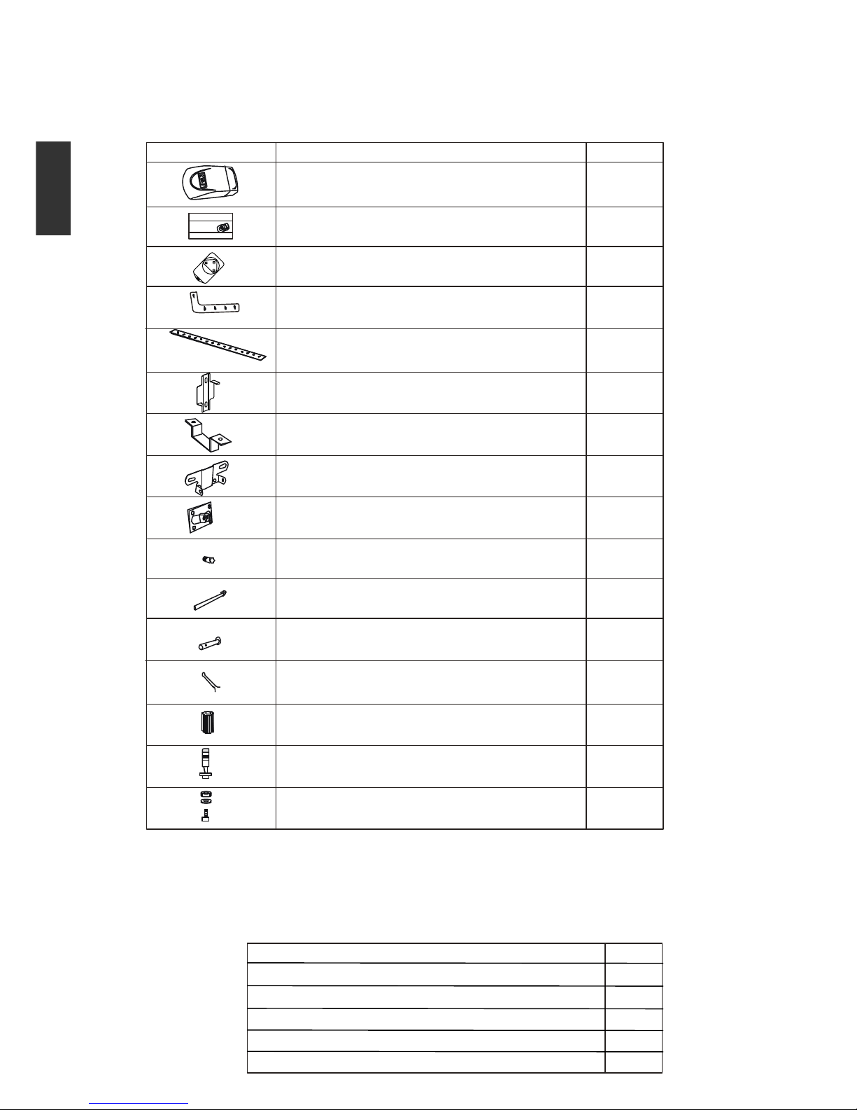
A. COMPONENTS LIST
The automation kit consists of two packs, as shown in the tables below:
Garage door opener pack
RAIL ASSEMBLY
1
2
1
1
1
1
1
1
6
4
8
3
1
1
1
1
Description Q.ty
Description Q.ty
Rail (1 m) 3
Straight door bracket 1
Chain 1
Emergency release rope 1
Trolley 1
Gearmotor with incorporated control unit
Instructions manual
Radio transmitter
Bent door arm
Mounting bracket
Support bracket
Front wall fixing bracket
Door fixing bracket
Screw with hexagonal nut 6x80
Inserted pin 8x25
Cotter pin 3x20
Pinion
Rawlplug 6x80
Screw with hexagonal nut 8x20
Hexagon-head driving screw 6x15
“U” bracket
1
GBGB
2
1
5 - 1
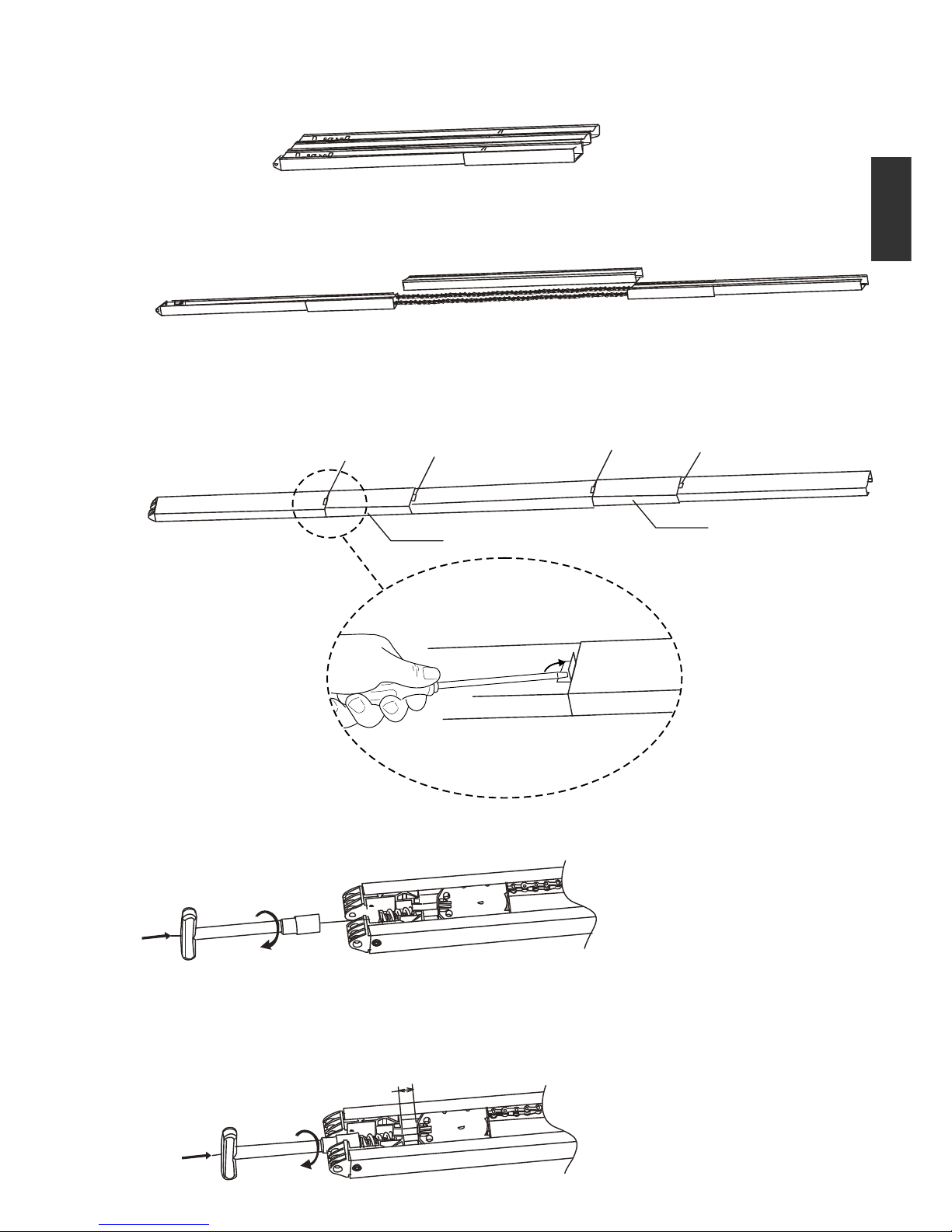
8 mm
1) Open the rail pack
2) Unfold the rail on the floor as shown in the picture
3) Join the rail parts together through the provided connectors in a way that
the catches are in sight
4) Tighten the nut with a Ø 13 sleeve
5) Adjust distance as shown in the picture
B. RAIL ASSEMBLY
Catch
Catch
Catch
Catch
Connector
Connector
GBGB
C. INSTALLATION
WARNING: FOLLOW THE MOUNTING INSTRUCTIONS CAREFULLY.
A FAULTY INSTALLATION MAY CAUSE SERIOUS INJURIES!
• Before proceeding with the installation, remove all unnecessary packages and disable any
unused equipment ;
• Make sure that the door can be easily opened and closed manually and check that it is in good
mechanical condition and properly balanced;
• Fix the garage door opener so that the emergency release rope can be reached at an height
lower than 1,8m from the floor;
• Install any automation system permanent controls within the door sight range but far enough from
any moving part and at a minimum height of 1,5m;
• Affix, in outstanding position or near the permanently mounted controls, warning signals
indicating the risk of being caught in the door movement;
• Clearly indicate the emergency release system;
• Once you have completed the installation, make sure that the mechanical structure is properly
adjusted and check that door reverses the closing movement when detecting any obstacle
higher than 40cm from the floor;
• Make sure that the door movement does not hinder public roads or footpaths;
• Make sure that the garage door opener stops any opening movement when a minimum load of
20 Kg is centrally fixedon the bottom edge of the door;
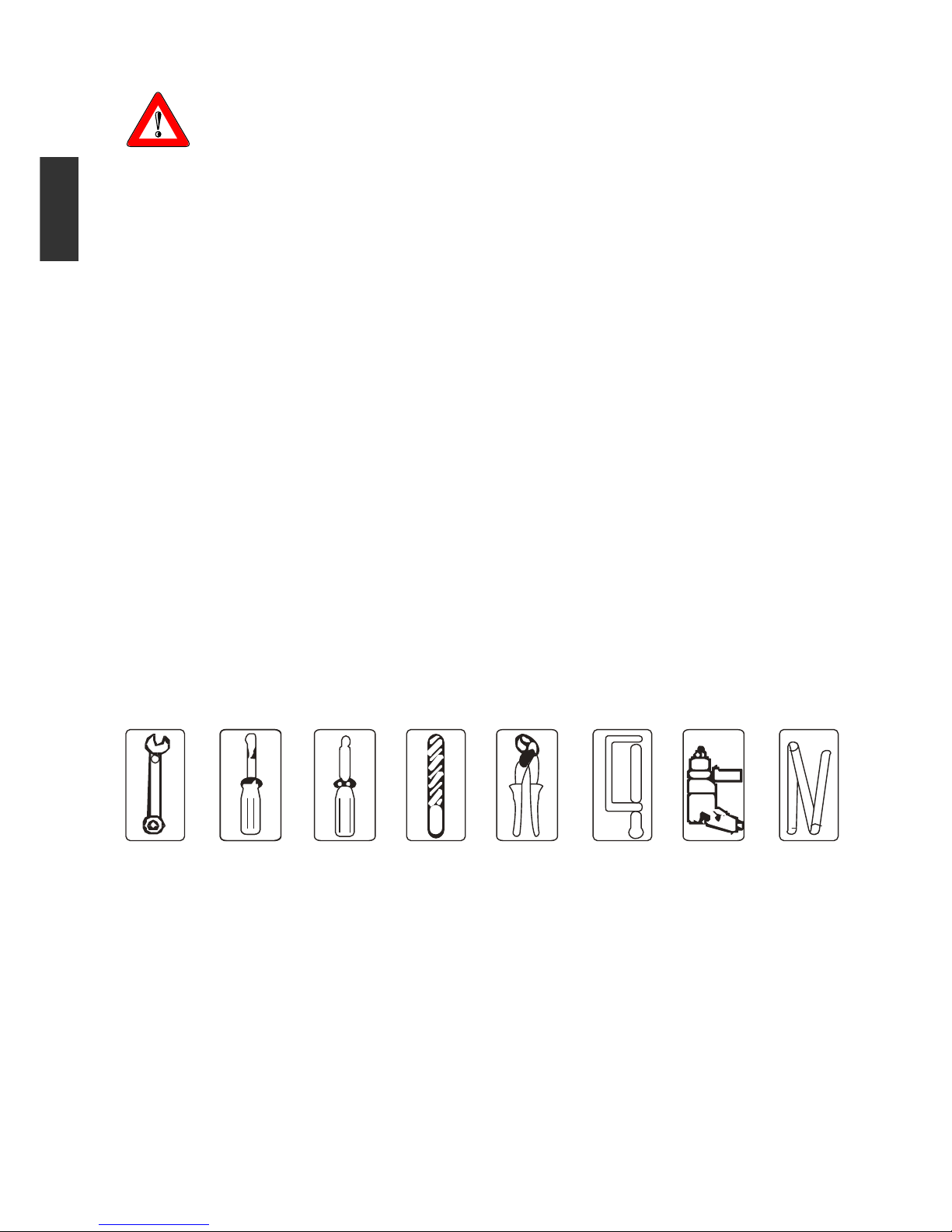
REQUIRED TOOLS
WARNING
3
GBGB
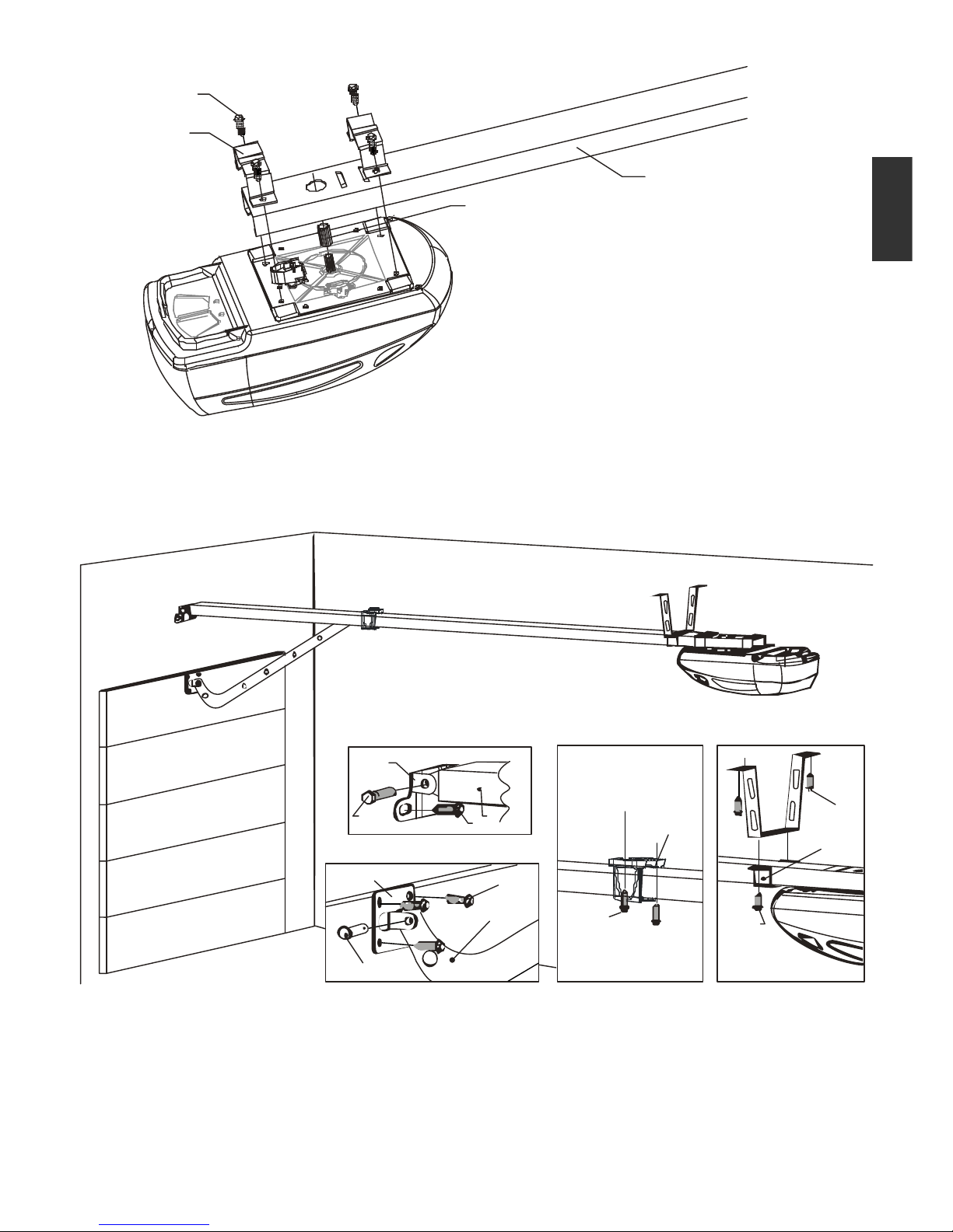
C1. GEARMOTOR ASSEMBLY TO THE RAIL
C2. GEARMOTOR AND RAIL FIXING
19
210
311
412
513
614
715
816
Front wall Driving screw 6x15
Door Bent door arm
Front wall fixing bracket Support bracket
Screw 6x80 Screw 8x20
Rail Mounting bracket
Rawlplug Rawlplug
Door fixing bracket “U” bracket
Inserted pin 8x25 Screw 8x20
1
2
3
4
5
6
7
8
9
10
11
12
13
14
15
16
1
2 “U”
3
4
Driving screws 6x15
bracket
Rail
Pinion
1
2
3
4
4
GBGB
 Loading...