

Liberty Systems CCR Liberty User Manual

Liberty
MANUAL

Content
Introduction . . . . . . . . . . . . . . . . . . . . . . . . . . . . . . . . . . . . . . . . . . . . . . . . . . . 6
Use of this manual . . . . . . . . . . . . . . . . . . . . . . . . . . . . . . . . . . . . . . . . . . . . . 6
Responsibility of the CCR Liberty user . . . . . . . . . . . . . . . . . . . . . . . . . . . . . 6
System of documentation . . . . . . . . . . . . . . . . . . . . . . . . . . . . . . . . . . . . 7
User support . . . . . . . . . . . . . . . . . . . . . . . . . . . . . . . . . . . . . . . . . . . . 7
Technical data . . . . . . . . . . . . . . . . . . . . . . . . . . . . . . . . . . . . . . . . . . . . . . . . . 8
Depth limits . . . . . . . . . . . . . . . . . . . . . . . . . . . . . . . . . . . . . . . . . . . . . . . . . 8
Water temperature limits . . . . . . . . . . . . . . . . . . . . . . . . . . . . . . . . . . . . . . . . . 8
CO2 scrubber duration limit . . . . . . . . . . . . . . . . . . . . . . . . . . . . . . . . . . . . . . . 8
Weight . . . . . . . . . . . . . . . . . . . . . . . . . . . . . . . . . . . . . . . . . . . . . . . . . . . . 9
1. Technical design . . . . . . . . . . . . . . . . . . . . . . . . . . . . . . . . . . . . . . . . . . . . 10
1.1 Basic schematic . . . . . . . . . . . . . . . . . . . . . . . . . . . . . . . . . . . . . . . . . . 12
1.2 Dive/surface valve . . . . . . . . . . . . . . . . . . . . . . . . . . . . . . . . . . . . . . . . 13
1.2.1 Inhalation valve . . . . . . . . . . . . . . . . . . . . . . . . . . . . . . . . . . . . 13
1.2.2 Exhalation valve . . . . . . . . . . . . . . . . . . . . . . . . . . . . . . . . . . . . 13
1.2.3 Mouthpiece . . . . . . . . . . . . . . . . . . . . . . . . . . . . . . . . . . . . . . . 14
1.2.4 Usage with a full face mask . . . . . . . . . . . . . . . . . . . . . . . . . . . . . 14
1.3 Corrugated hoses and accessories . . . . . . . . . . . . . . . . . . . . . . . . . . . . . . 15
1.3.1 Hoses . . . . . . . . . . . . . . . . . . . . . . . . . . . . . . . . . . . . . . . . . . . 15
1.3.2 Attachment to the head . . . . . . . . . . . . . . . . . . . . . . . . . . . . . . . 15
1.3.3 Connection to the breathing bags . . . . . . . . . . . . . . . . . . . . . . . . . 15
1.3.4 Attachment of the DSV . . . . . . . . . . . . . . . . . . . . . . . . . . . . . . . . 16
1.4 Inhalation bag . . . . . . . . . . . . . . . . . . . . . . . . . . . . . . . . . . . . . . . . . . . 16
1.4.1 Automatic diluent valve . . . . . . . . . . . . . . . . . . . . . . . . . . . . . . . 16
1.4.2 Manual diluent bypass valve . . . . . . . . . . . . . . . . . . . . . . . . . . . . . 17
1.5 Exhalation bag . . . . . . . . . . . . . . . . . . . . . . . . . . . . . . . . . . . . . . . . . . . 17
1.5.1 Manual oxygen bypass valve . . . . . . . . . . . . . . . . . . . . . . . . . . . . . 17
1.5.2 Overpressure valve . . . . . . . . . . . . . . . . . . . . . . . . . . . . . . . . . . . 18
1.6 Oxygen tank . . . . . . . . . . . . . . . . . . . . . . . . . . . . . . . . . . . . . . . . . . . . 18
1.6.1 Tank . . . . . . . . . . . . . . . . . . . . . . . . . . . . . . . . . . . . . . . . . . . . 18
1.6.2 Valve . . . . . . . . . . . . . . . . . . . . . . . . . . . . . . . . . . . . . . . . . . . 19
1.6.3 Reduction valve . . . . . . . . . . . . . . . . . . . . . . . . . . . . . . . . . . . . . 19
1.6.4 Pressure reading . . . . . . . . . . . . . . . . . . . . . . . . . . . . . . . . . . . . 19
1.7 Diluent tank . . . . . . . . . . . . . . . . . . . . . . . . . . . . . . . . . . . . . . . . . . . . 19
1

1.7.1 Tank . . . . . . . . . . . . . . . . . . . . . . . . . . . . . . . . . . . . . . . . . . . . 19
1.7.2 Valve . . . . . . . . . . . . . . . . . . . . . . . . . . . . . . . . . . . . . . . . . . . 20
1.7.3 Reduction valve and pressure reading . . . . . . . . . . . . . . . . . . . . . . . 20
1.7.4 Backup regulator (optional) . . . . . . . . . . . . . . . . . . . . . . . . . . . . . 20
1.8 CO2 scrubber . . . . . . . . . . . . . . . . . . . . . . . . . . . . . . . . . . . . . . . . . . . . 20
1.9 Head . . . . . . . . . . . . . . . . . . . . . . . . . . . . . . . . . . . . . . . . . . . . . . . . . 21
1.9.1 Control units . . . . . . . . . . . . . . . . . . . . . . . . . . . . . . . . . . . . . . 21
1.9.2 Direct measurement of ppO2 . . . . . . . . . . . . . . . . . . . . . . . . . . . . . 22
1.9.3 Measurement of He content . . . . . . . . . . . . . . . . . . . . . . . . . . . . . 23
1.9.4 Pressure and depth measurement . . . . . . . . . . . . . . . . . . . . . . . . . 24
1.9.5 Temperature measurement . . . . . . . . . . . . . . . . . . . . . . . . . . . . . 24
1.9.6 Solenoids . . . . . . . . . . . . . . . . . . . . . . . . . . . . . . . . . . . . . . . . 24
1.9.7 Power supply . . . . . . . . . . . . . . . . . . . . . . . . . . . . . . . . . . . . . . 24
1.10 Visual display units . . . . . . . . . . . . . . . . . . . . . . . . . . . . . . . . . . . . . . . . 25
1.10.1 Handsets . . . . . . . . . . . . . . . . . . . . . . . . . . . . . . . . . . . . . . . . . 25
1.10.2 Head-up display . . . . . . . . . . . . . . . . . . . . . . . . . . . . . . . . . . . . 25
1.10.3 Buddy display . . . . . . . . . . . . . . . . . . . . . . . . . . . . . . . . . . . . . . 25
1.11 Backplate and mounting . . . . . . . . . . . . . . . . . . . . . . . . . . . . . . . . . . . . 27
1.12 Harness . . . . . . . . . . . . . . . . . . . . . . . . . . . . . . . . . . . . . . . . . . . . . . . 28
1.13 Buoyancy compensator . . . . . . . . . . . . . . . . . . . . . . . . . . . . . . . . . . . . . 29
1.14 Ballast . . . . . . . . . . . . . . . . . . . . . . . . . . . . . . . . . . . . . . . . . . . . . . . . 29
1.15 Weights of individual parts . . . . . . . . . . . . . . . . . . . . . . . . . . . . . . . . . . . 30
2. Control-unit operation . . . . . . . . . . . . . . . . . . . . . . . . . . . . . . . . . . . . . . . . 31
2.1 Control elements . . . . . . . . . . . . . . . . . . . . . . . . . . . . . . . . . . . . . . . . . 31
2.1.1 Meanings of inputs in surface modes . . . . . . . . . . . . . . . . . . . . . . . 31
2.1.2 Meanings of inputs in dive modes . . . . . . . . . . . . . . . . . . . . . . . . . 32
2.1.3 Language . . . . . . . . . . . . . . . . . . . . . . . . . . . . . . . . . . . . . . . . 33
2.2 Switching on the unit . . . . . . . . . . . . . . . . . . . . . . . . . . . . . . . . . . . . . . . 33
2.2.1 Activation . . . . . . . . . . . . . . . . . . . . . . . . . . . . . . . . . . . . . . . . 33
2.3 Surface mode . . . . . . . . . . . . . . . . . . . . . . . . . . . . . . . . . . . . . . . . . . . 34
2.3.1 Entering surface mode . . . . . . . . . . . . . . . . . . . . . . . . . . . . . . . . 34
2.3.2 Surface mode primary screen . . . . . . . . . . . . . . . . . . . . . . . . . . . . 34
2.3.3 Surface mode O2 sensors screen . . . . . . . . . . . . . . . . . . . . . . . . . . 35
2.3.4 Switching to other modes . . . . . . . . . . . . . . . . . . . . . . . . . . . . . . 35
2.3.5 ppO2 control in surface mode . . . . . . . . . . . . . . . . . . . . . . . . . . . . 36
2.4 Setup . . . . . . . . . . . . . . . . . . . . . . . . . . . . . . . . . . . . . . . . . . . . . . . . 36
2.4.1 Editor use . . . . . . . . . . . . . . . . . . . . . . . . . . . . . . . . . . . . . . . . 37
2.4.2 Setpoints . . . . . . . . . . . . . . . . . . . . . . . . . . . . . . . . . . . . . . . . . 37
2.4.3 Mixtures . . . . . . . . . . . . . . . . . . . . . . . . . . . . . . . . . . . . . . . . . 38
2

2.4.4 Decompression . . . . . . . . . . . . . . . . . . . . . . . . . . . . . . . . . . . . . 40
2.4.5 Alarms . . . . . . . . . . . . . . . . . . . . . . . . . . . . . . . . . . . . . . . . . . 42
2.4.6 Preferences . . . . . . . . . . . . . . . . . . . . . . . . . . . . . . . . . . . . . . . 44
2.4.7 Calibration . . . . . . . . . . . . . . . . . . . . . . . . . . . . . . . . . . . . . . . . 45
2.4.8 Faulty sensors . . . . . . . . . . . . . . . . . . . . . . . . . . . . . . . . . . . . . 46
2.4.9 Miscellaneous . . . . . . . . . . . . . . . . . . . . . . . . . . . . . . . . . . . . . 47
2.5 Dive mode . . . . . . . . . . . . . . . . . . . . . . . . . . . . . . . . . . . . . . . . . . . . . . 48
2.5.1 Detailed screen . . . . . . . . . . . . . . . . . . . . . . . . . . . . . . . . . . . . . 48
2.5.2 Synoptic screen . . . . . . . . . . . . . . . . . . . . . . . . . . . . . . . . . . . . 51
2.5.3 Big Screen . . . . . . . . . . . . . . . . . . . . . . . . . . . . . . . . . . . . . . . . 51
2.5.4 Dive profile screen . . . . . . . . . . . . . . . . . . . . . . . . . . . . . . . . . . . 52
2.5.5 Sensors screen . . . . . . . . . . . . . . . . . . . . . . . . . . . . . . . . . . . . . 52
2.5.6 TTS Screen . . . . . . . . . . . . . . . . . . . . . . . . . . . . . . . . . . . . . . . . 53
2.6 CCR mode . . . . . . . . . . . . . . . . . . . . . . . . . . . . . . . . . . . . . . . . . . . . . . 53
2.6.1 Entering CCR mode . . . . . . . . . . . . . . . . . . . . . . . . . . . . . . . . . . 53
2.6.2 Switching to other modes . . . . . . . . . . . . . . . . . . . . . . . . . . . . . . 54
2.6.3 ppO2 regulation . . . . . . . . . . . . . . . . . . . . . . . . . . . . . . . . . . . . . 55
2.6.4 Decompression . . . . . . . . . . . . . . . . . . . . . . . . . . . . . . . . . . . . . 57
2.6.5 Specific handset control . . . . . . . . . . . . . . . . . . . . . . . . . . . . . . . 57
2.7 Manual CCR mode . . . . . . . . . . . . . . . . . . . . . . . . . . . . . . . . . . . . . . . . . 57
2.7.1 Entering manual CCR mode . . . . . . . . . . . . . . . . . . . . . . . . . . . . . 57
2.7.2 Switching to other modes . . . . . . . . . . . . . . . . . . . . . . . . . . . . . . 57
2.7.3 ppO2 regulation . . . . . . . . . . . . . . . . . . . . . . . . . . . . . . . . . . . . . 57
2.7.4 Decompression . . . . . . . . . . . . . . . . . . . . . . . . . . . . . . . . . . . . . 58
2.8 Bailout OC mode . . . . . . . . . . . . . . . . . . . . . . . . . . . . . . . . . . . . . . . . . 58
2.8.1 Entering bailout OC mode . . . . . . . . . . . . . . . . . . . . . . . . . . . . . . 58
2.8.2 Switching to other modes . . . . . . . . . . . . . . . . . . . . . . . . . . . . . . 58
2.8.3 Mixture . . . . . . . . . . . . . . . . . . . . . . . . . . . . . . . . . . . . . . . . . . 58
2.8.4 Decompression . . . . . . . . . . . . . . . . . . . . . . . . . . . . . . . . . . . . . 59
2.8.5 Specific handset control . . . . . . . . . . . . . . . . . . . . . . . . . . . . . . . 59
2.9 Ascent plan . . . . . . . . . . . . . . . . . . . . . . . . . . . . . . . . . . . . . . . . . . . . . 59
2.10 Setup in Dive mode . . . . . . . . . . . . . . . . . . . . . . . . . . . . . . . . . . . . . . . . 60
2.11 Games . . . . . . . . . . . . . . . . . . . . . . . . . . . . . . . . . . . . . . . . . . . . . . . . 61
2.11.1 Sokoban . . . . . . . . . . . . . . . . . . . . . . . . . . . . . . . . . . . . . . . . . 62
2.11.2 Snake . . . . . . . . . . . . . . . . . . . . . . . . . . . . . . . . . . . . . . . . . . . 62
3. Procedures . . . . . . . . . . . . . . . . . . . . . . . . . . . . . . . . . . . . . . . . . . . . . . . . 63
3.1 Dive plan . . . . . . . . . . . . . . . . . . . . . . . . . . . . . . . . . . . . . . . . . . . . . . 63
3.1.1 Planner settings . . . . . . . . . . . . . . . . . . . . . . . . . . . . . . . . . . . . 63
3.1.2 Planning . . . . . . . . . . . . . . . . . . . . . . . . . . . . . . . . . . . . . . . . . 64
3

3.2 Dive preparation . . . . . . . . . . . . . . . . . . . . . . . . . . . . . . . . . . . . . . . . . . 66
3.2.1 Replacement of CO2 sorbent . . . . . . . . . . . . . . . . . . . . . . . . . . . . . 66
3.2.2 Assembling the rebreather body . . . . . . . . . . . . . . . . . . . . . . . . . . 70
3.2.3 Mounting the rebreather body . . . . . . . . . . . . . . . . . . . . . . . . . . . . 70
3.2.4 Attaching the counterlungs and hoses . . . . . . . . . . . . . . . . . . . . . . 71
3.2.5 Tank filling . . . . . . . . . . . . . . . . . . . . . . . . . . . . . . . . . . . . . . . . 72
3.2.6 Battery charging . . . . . . . . . . . . . . . . . . . . . . . . . . . . . . . . . . . . 74
3.2.7 Helium sensor calibration . . . . . . . . . . . . . . . . . . . . . . . . . . . . . . 74
3.2.8 Calibration of the oxygen sensors . . . . . . . . . . . . . . . . . . . . . . . . . 75
3.2.9 Preparing the bailout apparatus . . . . . . . . . . . . . . . . . . . . . . . . . . 76
3.2.10 Setting parameters . . . . . . . . . . . . . . . . . . . . . . . . . . . . . . . . . . 76
3.2.11 Directional valve check . . . . . . . . . . . . . . . . . . . . . . . . . . . . . . . . 76
3.2.12 Physical inspection . . . . . . . . . . . . . . . . . . . . . . . . . . . . . . . . . . 77
3.3 Pre-dive inspection . . . . . . . . . . . . . . . . . . . . . . . . . . . . . . . . . . . . . . . . 77
3.3.1 Internal testing of the control units . . . . . . . . . . . . . . . . . . . . . . . . 78
3.3.2 Pressure sensor test . . . . . . . . . . . . . . . . . . . . . . . . . . . . . . . . . 78
3.3.3 Comparison of oxygen sensors and their calibration . . . . . . . . . . . . . . 79
3.3.4 Helium-sensor test . . . . . . . . . . . . . . . . . . . . . . . . . . . . . . . . . . 79
3.3.5 Battery testing . . . . . . . . . . . . . . . . . . . . . . . . . . . . . . . . . . . . . 80
3.3.6 Solenoid testing . . . . . . . . . . . . . . . . . . . . . . . . . . . . . . . . . . . . 80
3.3.7 HUD inspection . . . . . . . . . . . . . . . . . . . . . . . . . . . . . . . . . . . . . 80
3.3.8 BD inspection . . . . . . . . . . . . . . . . . . . . . . . . . . . . . . . . . . . . . . 81
3.3.9 Negative pressure test . . . . . . . . . . . . . . . . . . . . . . . . . . . . . . . . 81
3.3.10 Positive pressure test . . . . . . . . . . . . . . . . . . . . . . . . . . . . . . . . . 82
3.3.11 Predive checklist . . . . . . . . . . . . . . . . . . . . . . . . . . . . . . . . . . . . 82
3.3.12 Prebreathe . . . . . . . . . . . . . . . . . . . . . . . . . . . . . . . . . . . . . . . . 83
3.4 Diving . . . . . . . . . . . . . . . . . . . . . . . . . . . . . . . . . . . . . . . . . . . . . . . . 85
3.4.1 Breathing high oxygen content gases . . . . . . . . . . . . . . . . . . . . . . . 85
3.4.2 Putting on the apparatus . . . . . . . . . . . . . . . . . . . . . . . . . . . . . . . 86
3.4.3 Using the DSV . . . . . . . . . . . . . . . . . . . . . . . . . . . . . . . . . . . . . . 87
3.4.4 Monitoring of devices . . . . . . . . . . . . . . . . . . . . . . . . . . . . . . . . . 87
3.4.5 Switching to CCR mode . . . . . . . . . . . . . . . . . . . . . . . . . . . . . . . . 88
3.4.6 Water entry . . . . . . . . . . . . . . . . . . . . . . . . . . . . . . . . . . . . . . . 88
3.4.7 Submersion . . . . . . . . . . . . . . . . . . . . . . . . . . . . . . . . . . . . . . . 89
3.4.8 In-water check . . . . . . . . . . . . . . . . . . . . . . . . . . . . . . . . . . . . . 89
3.4.9 Descent . . . . . . . . . . . . . . . . . . . . . . . . . . . . . . . . . . . . . . . . . 89
3.4.10 Controlling buoyancy and trim . . . . . . . . . . . . . . . . . . . . . . . . . . . 90
3.4.11 Mask clearing . . . . . . . . . . . . . . . . . . . . . . . . . . . . . . . . . . . . . . 91
3.4.12 Increased physical exertion . . . . . . . . . . . . . . . . . . . . . . . . . . . . . 91
3.4.13 Ascent . . . . . . . . . . . . . . . . . . . . . . . . . . . . . . . . . . . . . . . . . . 91
4

3.5 Post-dive procedures . . . . . . . . . . . . . . . . . . . . . . . . . . . . . . . . . . . . . . . 92
3.5.1 Immediately after surfacing . . . . . . . . . . . . . . . . . . . . . . . . . . . . . 92
3.5.2 CO2 scrubber maintenance . . . . . . . . . . . . . . . . . . . . . . . . . . . . . . 92
3.5.3 Cleaning and disinfection . . . . . . . . . . . . . . . . . . . . . . . . . . . . . . 93
3.5.4 Battery care . . . . . . . . . . . . . . . . . . . . . . . . . . . . . . . . . . . . . . . 94
3.5.5 Dive log download . . . . . . . . . . . . . . . . . . . . . . . . . . . . . . . . . . . 95
3.5.6 Long-term storage . . . . . . . . . . . . . . . . . . . . . . . . . . . . . . . . . . . 95
3.6 Emergency procedures . . . . . . . . . . . . . . . . . . . . . . . . . . . . . . . . . . . . . 96
3.6.1 Emergency ascent (bailout) . . . . . . . . . . . . . . . . . . . . . . . . . . . . . 96
3.6.2 Oxygen-source malfunction . . . . . . . . . . . . . . . . . . . . . . . . . . . . . 97
3.6.3 Diluent-source malfunction . . . . . . . . . . . . . . . . . . . . . . . . . . . . . 98
3.6.4 Scrubber malfunction . . . . . . . . . . . . . . . . . . . . . . . . . . . . . . . . . 99
3.6.5 Inadvertent release of the mouthpiece . . . . . . . . . . . . . . . . . . . . . 100
3.6.6 Flooding . . . . . . . . . . . . . . . . . . . . . . . . . . . . . . . . . . . . . . . . 100
3.6.7 Loss of buoyancy . . . . . . . . . . . . . . . . . . . . . . . . . . . . . . . . . . . 101
3.6.8 Rescue on the surface . . . . . . . . . . . . . . . . . . . . . . . . . . . . . . . 101
3.6.9 Malfunction of oxygen-concentration measuring . . . . . . . . . . . . . . . 102
3.7 Maintenance . . . . . . . . . . . . . . . . . . . . . . . . . . . . . . . . . . . . . . . . . . . 102
3.7.1 Tools and replacement parts . . . . . . . . . . . . . . . . . . . . . . . . . . . 102
3.7.2 Detection of leaks . . . . . . . . . . . . . . . . . . . . . . . . . . . . . . . . . . 103
3.7.3 Regular service inspection . . . . . . . . . . . . . . . . . . . . . . . . . . . . . 103
3.7.4 Long-term maintenance . . . . . . . . . . . . . . . . . . . . . . . . . . . . . . 103
3.7.5 Firmware update . . . . . . . . . . . . . . . . . . . . . . . . . . . . . . . . . . . 104
3.8 Transport . . . . . . . . . . . . . . . . . . . . . . . . . . . . . . . . . . . . . . . . . . . . . 106
3.8.1 By car . . . . . . . . . . . . . . . . . . . . . . . . . . . . . . . . . . . . . . . . . . 106
3.8.2 By boat . . . . . . . . . . . . . . . . . . . . . . . . . . . . . . . . . . . . . . . . . 106
3.8.3 By plane . . . . . . . . . . . . . . . . . . . . . . . . . . . . . . . . . . . . . . . . 107
5

Introduction
Use of this manual
This user manual is part of the CCR Liberty documentation.
The CCR Liberty is intended to be used exclusively by a trained person who is capable of fully
understanding the instructions contained in this manual or is in the process of training with
the CCR Liberty in a course accredited by the manufacturer. The initial requirements of such
a training course include qualification for diving with trimix recognized by a training agency
and sufficient experience with technical diving.
Responsibility of the CCR Liberty user
Strong emphasis was placed on reliability during the development of the CCR Liberty. Individual
internal parts are separated in order to minimize the impact that failure of any given part
may have on the rebreather’s basic functionality. A number of systems have multiple backups.
The logic of the CCR Liberty’s control never prohibits the start of a dive even in the event that
malfunctions are detected; it only indicates the status if able to do so in light of the damage.
When cave diving, the inability to submerge can mean not being able to return from a dive;
therefore, the CCR Liberty does not impede submersion.
The user must always decide responsibly whether he/she switches to a backup apparatus or
even starts a dive with a partially malfunctioning rebreather.
A CCR Liberty user must accept the fact that diving involves risk. Following everything that
the user has learned in the CCR Liberty’s technical documentation and in training on diving
with this rebreather can reduce the risk but cannot eliminate it. Safety when diving is further
improved by regular training, methodical education and following good diving practices. Diving
with a rebreather requires a far higher degree of carefulness and discipline than diving with an
open-circuit apparatus.
If you do not accept the risk and you are not a trained, careful and disciplined diver, do not dive
with the CCR Liberty.
The manufacturer does not bear any responsibility for use of the CCR Liberty if the apparatus
has been modified in any way that is not stated in this manual or in the technical guidelines
issued by the manufacturer.
6

System of documentation
Version
The technical documentation is subjected to a process of continual development and
improvement. Therefore, please regularly check the website at www.CCRLiberty.com for
updates.
This manual provides operating instructions for the hardware and software (firmware) version
of the CCR Liberty written on the tittle page.
Technical guidelines
The manufacturer can issue technical guidelines. It is strongly recommended that the user
regularly checks www.CCRLiberty.com for new guidelines. Registered users will receive
notifications by e-mail.
Update of printed documentation
The electronic form of the manual is always available in its complete, updated form.
The electronic and printed forms of the manual may not be completely identical. In case of
insignificant changes (correction of minor typing errors, for example), only the electronic
version is updated.
User support
Registered users are entitled to technical support. The extent of free support can be limited.
The technical support department at Liberty systems s.r.o. will provide limited support for
potential and unregistered users. Prior to submitting a question, please familiarize yourself
with the general principles of rebreather diving with trimix and the freely available CCR Liberty
technical documentation.
7

Technical data
Depth limits
The maximum depth for which The CCR Liberty meets the requirements of the Harmonized
Standard EN 14143:2013 is 100 m.
Diluent Max. depth
Air 40 m
tmx 21/35 66 m
tmx 18/45 78 m
tmx (heliox) 10/90 > 78 m
Additional limitation of depth depends on the used diluent, see 72 Tank filling – Diluent.
The CCR Liberty currently is configured with Apeks Environmentally sealed DST4 1st stages,
the Maximum Operational Depth of the unit with this 1st stage configuration is 170 m. Beyond
170 meters the gas reduction valves ie. 1st stage regulators MUST be replaced with the Apeks
UST4 Environmentally unsealed 1st stage kit.
All components are tested in overpressure 6 MPa (depth 600 m). The depth gauge is checked
and calibrated in overpressure 3.5 MPa (depth 350 m). EC Type-examination was performed to
a 100 m simulated depth.
Water temperature limits
The CCR Liberty is intended for use in water temperatures above 4 °C and below 34 °C
according to the requirements of EN 14143:2013 (Article 5.1).
The minimal temperature is determined through CO2 scrubber duration tests, which are done
at 4 °C.
CO2 scrubber duration limit
The maximum safe operating period of the sorbent is 168 min, determined by a test in
accordance to EN 14143:2013 (Article 6.6.2). During the test 1.6 l/min of CO2 were added to the
8

breathing loop with ventilation of 40 l/min in water with temperature 4 °C, exhaled gas with
temperature 32±4 °C, 40 m depth and limit at ppCO2 5 mBar.
The sorbent’s actual maximum operating period can differ depending on the sorbent,
temperature, depth and the diver’s physical effort.
In normal conditions scrubber duration is considered to range from 4 h in deep cold water with
moderate work to 6 hours for an easy dive. For details see 66 Sorbent service life.
Weight
The total weight of The CCR Liberty, readied for a dive, including fillings, is approx. 37 kg.
For details see 30 Weights of individual parts.
The recommended service intervals are at 1 year, 3 years and 5 years.
The servicing of the unit can only be performed by authorised service technician or technical
centre.
Not performing services at regular intervals may result in voiding your warranty.
Date of issue: 29. June 2018
CU HW rev. 1.4, HS HW rev. 3.0, FW 2.11
Authors: Adam Procháska, Jakub Šimánek, Aleš Procháska
Published by Liberty systems s.r.o., CCRLiberty.com
9
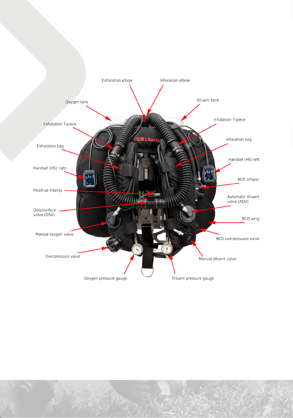
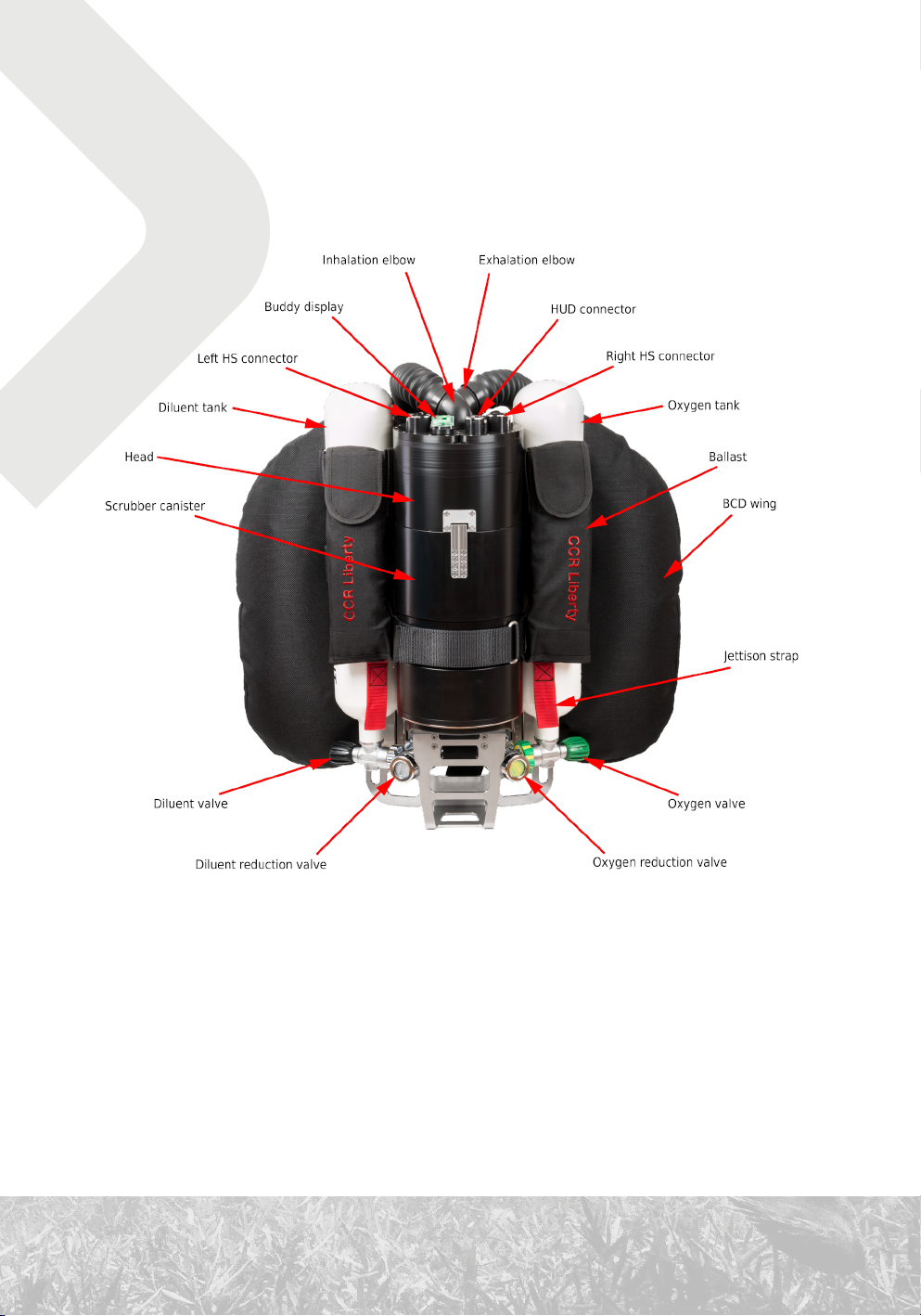
1. Technical design
10
11
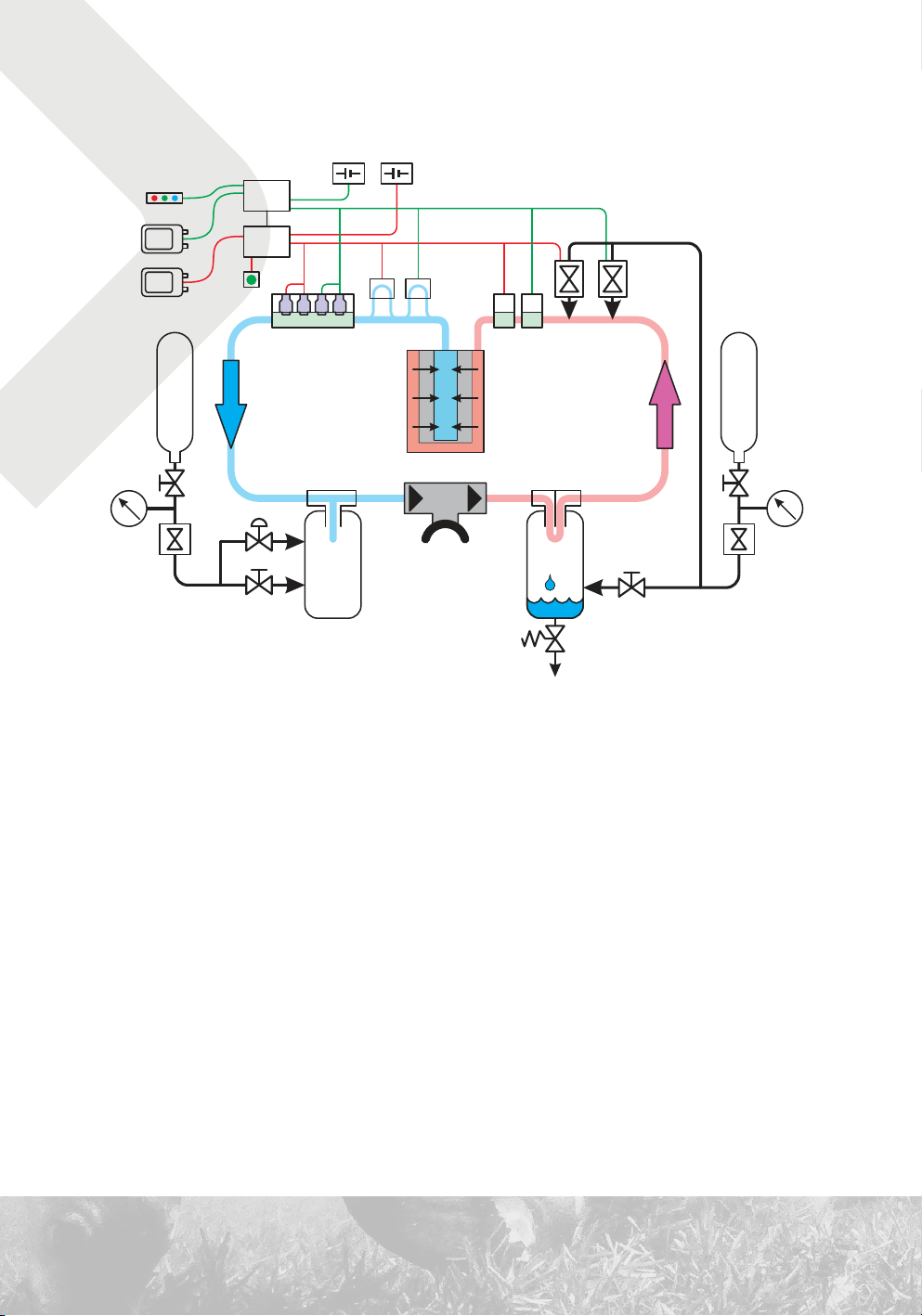
1.1 Basic schematic
Displayunits
Diluent
reduction
valve
HUD
HS
HS
Buddy
display
DILUENT
Manualdiluentvalve
Controlunits
ADV
CU
CU
ppO sensors
2
Inhalation
bag
Rechargeablebatteries
He%
sensors
Pressure
&temperature
sensors
CO absorbent
Dive/surface
valve
Watertrap
Overpressure
valve
2
Exhalation
bag
Solenoid
valves
Manualoxygenvalve
OXYGEN
Oxygen
reduction
valve
The principle of the rebreather consists in recycling the breathing mixture. Carbon dioxide
is removed from the exhaled mixture and is again prepared for the next inhalation after
replenishment with oxygen. The composition of the breathing mixture changes continuously.
12
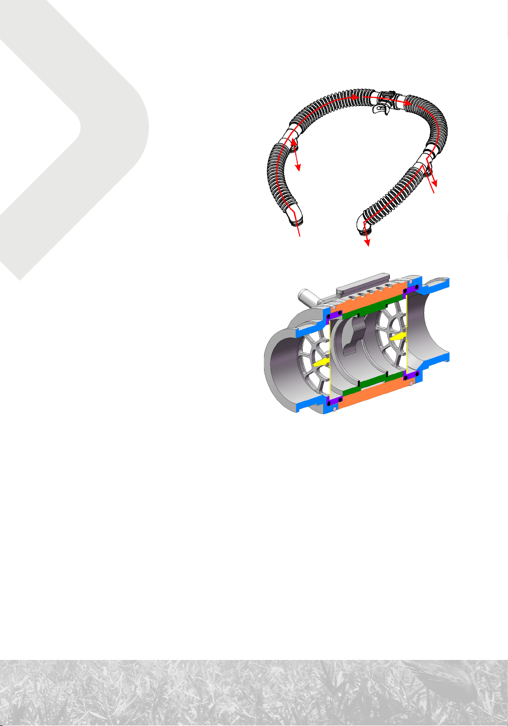
1.2 Dive/surface valve
The breathing mixture is delivered to the
dive/surface valve (DSV) through the
corrugated hose from the left. When inhaling,
the mixture passes through the inhalation
valve to the mouthpiece and then into the
diver’s respiratory tract. When exhaling, it
passes through the exhalation valve into the
corrugated hose on the right.
The direction of the mixture’s flow is indicated
on the DSV.
1.2.1 Inhalation valve
The inhalation valve ensures that the
exhaled mixture cannot directly return to the
inhalation bag and is not repeatedly inhaled
by the diver without the removal of carbon
dioxide and the addition of oxygen.
The inhalation valve is situated within the
connection of the left corrugated hose.
A similar mushroom valve can be found in, for example, the exhalation valve of the second
stage of the regulator of an open-circuit apparatus.
This is one of the most critical parts of the rebreather. It is difficult to detect a malfunction in
this part during a dive, and such a malfunction can lead to loss of consciousness.
1.2.2 Exhalation valve
The exhalation valve directs the exhaled mixture via the corrugated hose to the exhalation bag.
It ensures that the diver does not directly re-inhale the exhaled mixture.
The exhalation valve is situated within the connection of the right corrugated hose.
13
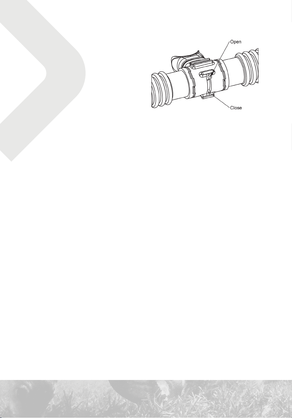
Closing the dive/surface valve
If the diver is in the water and not using the
DSV, the DSV must be closed. Otherwise, the
circuit will be flooded with water.
Closing the DSV is done by using the gate
handle in the front part of the DSV. In the open
position, the handle is put up; in the closed
position, it is down.
1.2.3 Mouthpiece
Tightly sealed mouthpiece in the diver’s mouth prevents water from entering into the circuit.
The DSV and corrugated hoses function with greater force than the regulator of an open-circuit
apparatus. Therefore, an anatomically suitable shape of the rebreather’s mouthpiece and
proper clenching in the mouth are very important.
We do not recommend using a mouthpiece that can be shaped to the diver’s bite after heating.
This kind of mouthpiece restricts the movement of the lower jaw, which leads to unilateral
stress and will rapidly exhaust the mastication muscles.
1.2.4 Usage with a full face mask
Even though the mechanical dimensions would allow the connection of the DSV to a full face
mask, in a full face mask it is not possible to switch the mixture inlet from an open circuit with
an inlet from a rebreather. One of the reasons for this is the necessity of defogging the visor.
Consult with the manufacturer regarding possibilities of connecting the rebreather to a full
face mask. Use of such an apparatus will require procedures that deviate from this manual and
from standard procedures taught in a course accredited by the rebreather’s manufacturer.
14
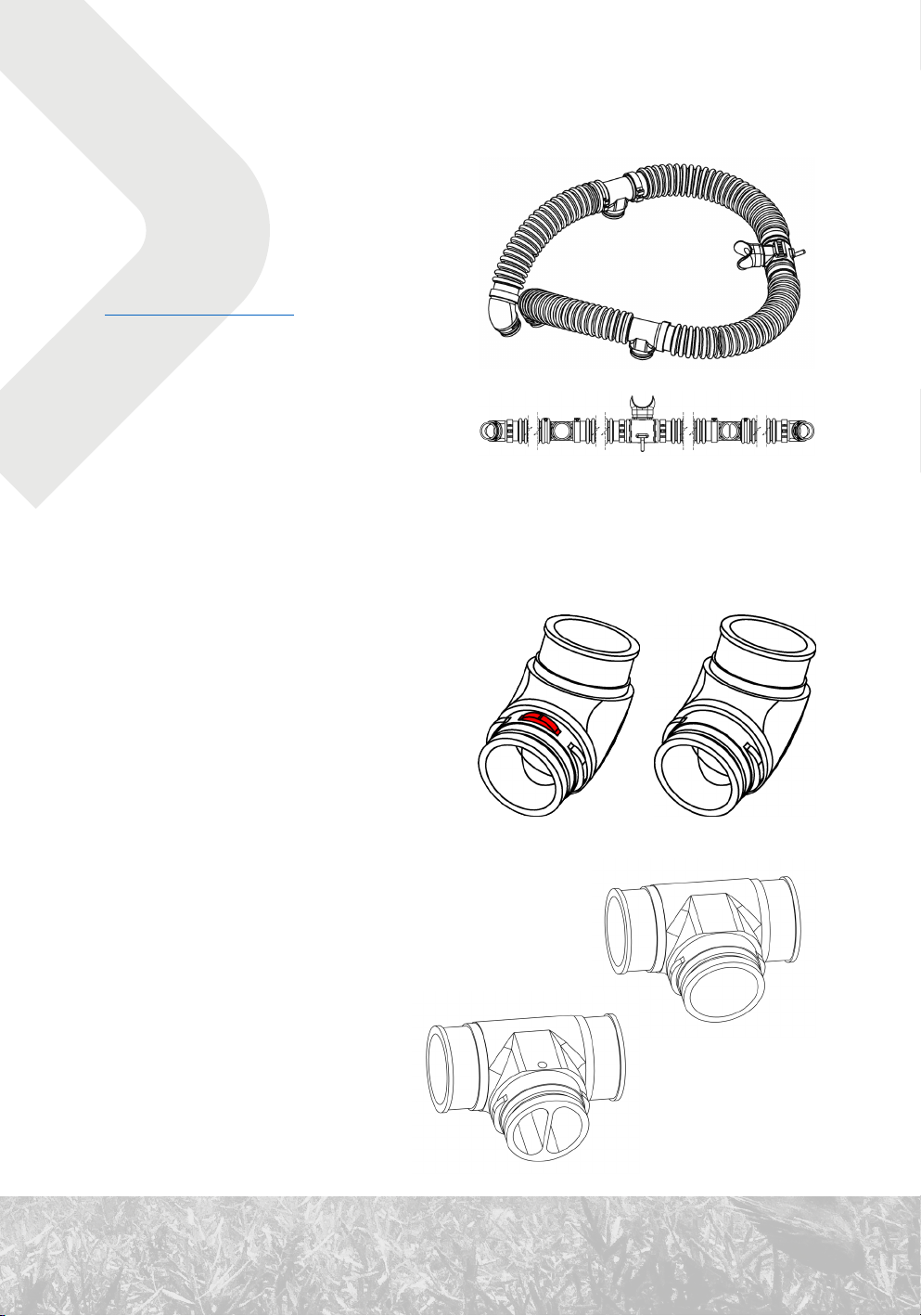
1.3 Corrugated hoses and accessories
1.3.1 Hoses
The corrugated hoses are made of EPDM
rubber. Compatible chemical agents must
be used for cleaning and disinfection (see 92
Cleaning and disinfection).
The corrugated hoses can be damaged if
subjected to excessive stress. In particular, it
is necessary to avoid perforation, cutting and
excessive wear. Avoid long-term deformation
of the hose, for example when storing the unit.
Do not use the hoses as a handle.
The corrugated hoses are one of the least durable mechanical parts of the CCR Liberty. Pay
appropriate attention to protecting them.
1.3.2 Attachment to the head
Unlike almost all other bayonet connectors
on the CCR Liberty, the bayonet connector on
the exhalation side has three protrusions. This
prevents incorrect attachment of the hoses.
Elbow on the exhalation side (left) and
inhalation side (right).
1.3.3 Connection to the breathing bags
The T-pieces have standard bayonet connections. On the
exhalation side, the T-piece has a partition that directs any
water that has entered the DSV to the exhalation bag and
improves the blending of the
mixture with oxygen added using
the manual bypass valve.
15
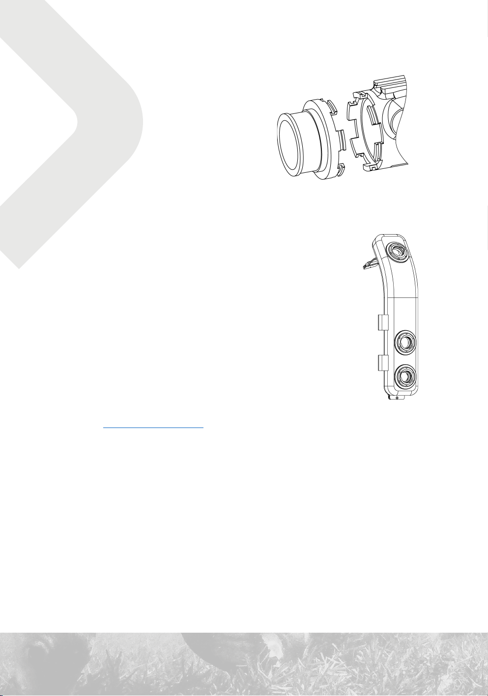
1.3.4 Attachment of the DSV
Attachment to the corrugated hoses is done
with axial teeth that fit together and are
secured with a wire retaining ring.
The baskets of the mushroom valves are
inserted into the connector. When handling
the baskets, pay attention to their correct
orientation.
1.4 Inhalation bag
The inhalation bag is mounted on the left part of the harness (from the
diver’s perspective when wearing the CCR Liberty).
The external cover is made from a resilient textile, ensuring mechanical
protection. The internal bag is made from polyurethane. It is connected to
the breathing circuit with a T-piece via the upper bulkhead with a bayonet
connector.
The inhalation bag is affixed to the harness with two stainless-steel
buckles and with Velcro flaps. It can be easily removed for cleaning,
disinfection and other handling.
See also 92 Cleaning and disinfection.
1.4.1 Automatic diluent valve
The automatic diluent valve (ADV) is mounted in the middle bulkhead with a bayonet connector.
When the volume of the inhalation bag decreases, the ADV is pressed. The ADV then
automatically adds diluent to the breathing circuit.
The ADV can be closed by sliding the collar.
The sensitivity of the ADV can be decreased with an additional spring, which is included as
a spare part.
16
1.4.2 Manual diluent bypass valve
The manual diluent bypass valve is situated in the lower bulkhead of the inhalation bag and is
equipped with a bayonet connector.
It is attached to the low pressure (LP) hose with a seatec-style quick-release connector.
It is operated by pressing the center button.
The safety lock prevents diluent valve from accidentally falling out. Follow
these steps to remove.
1.5 Exhalation bag
The exhalation bag is situated on the right side of the harness It’s design and
the way it is connected to the harness and the breathing loop are similar to
those of the inhalation bag.
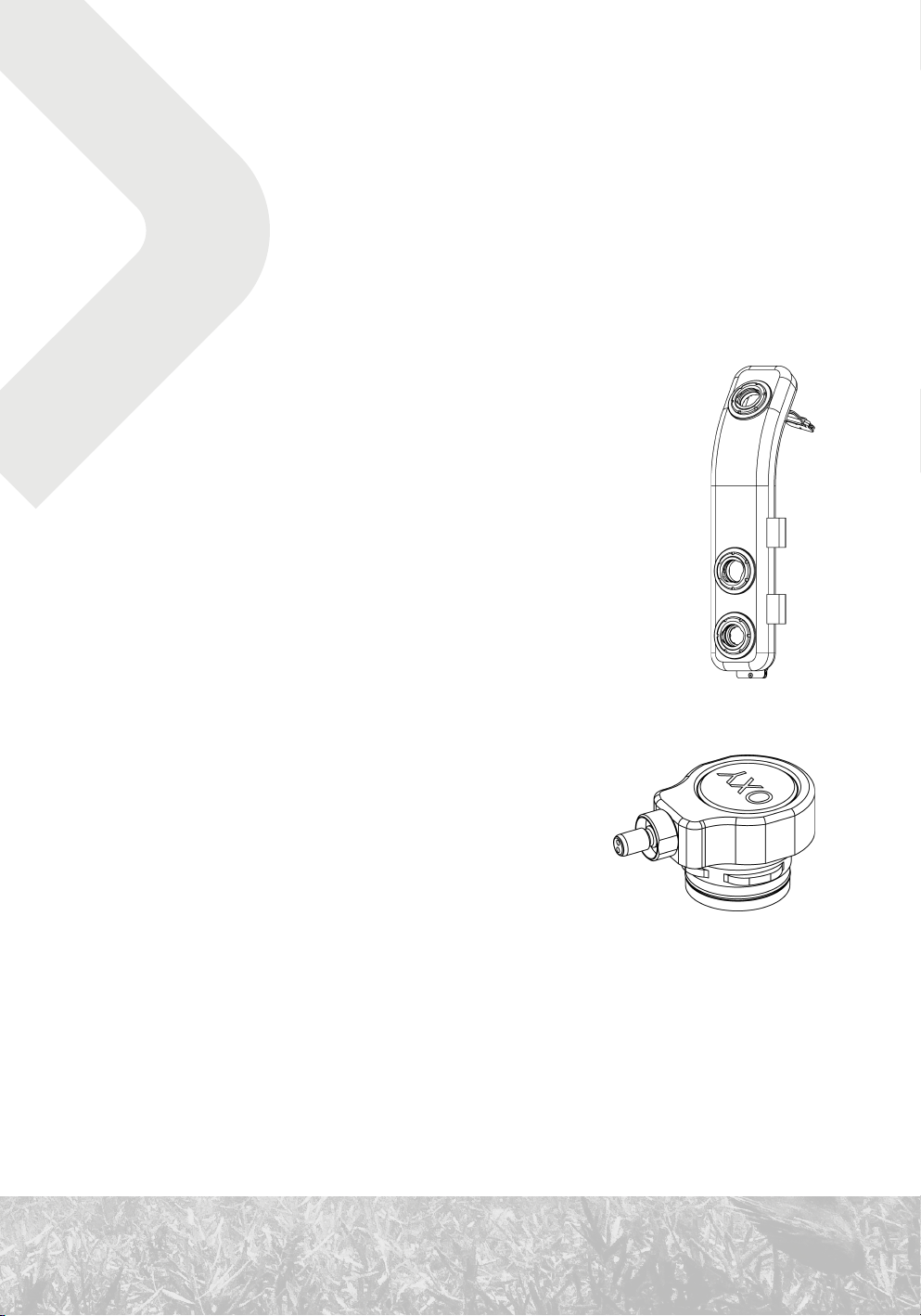
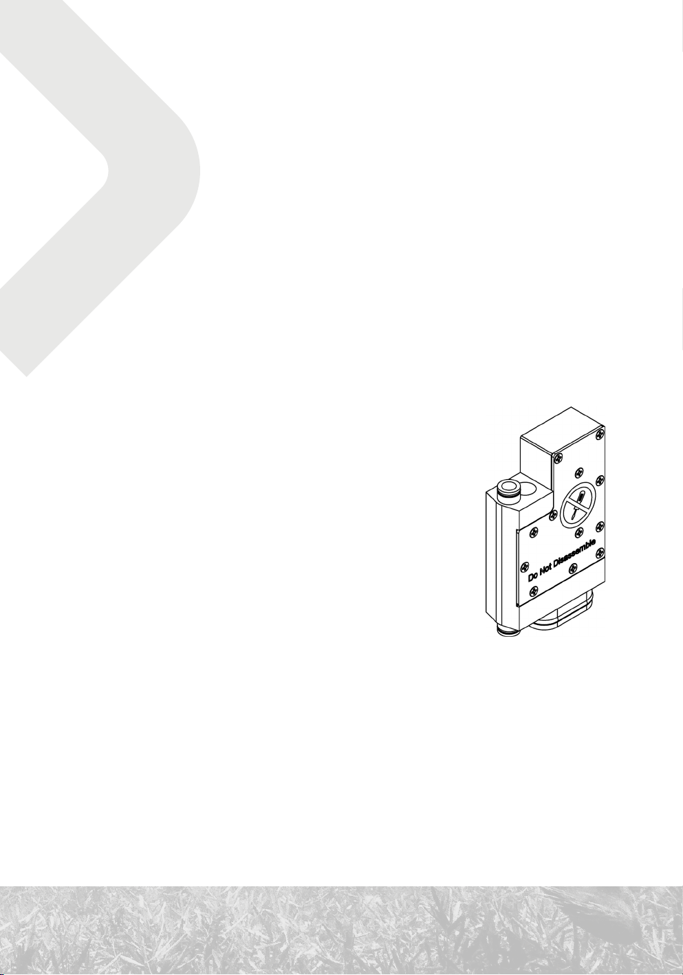
1.5.1 Manual oxygen bypass valve
The manual oxygen bypass valve is situated in the middle
bulkhead of the exhalation bag and is equipped with a bayonet
connector.
It is attached to the intermediate pressure hose with an oxygen
quick-release connector. This connector is like a standard
seatec-style quick-release connector with a collar. A standard
connector cannot be connected to the oxygen quick-release
connector. Though it is possible to connect the oxygen hose to the normal connector. Do not
remove the collar from the oxygen connector as connecting the wrong gas to the wrong valve
could potentially be dangerous. This is a requirement of the EN 14141 norm.
The bayonet connector on the oxygen bypass valve has three protrusions.
Use oxygen-compatible lubricant for maintenance of the oxygen bypass valve (We recommend
DuPont Krytox GPL-226).
17
1.5.2 Overpressure valve
The overpressure valve (OPV) is mounted in the lower bulkhead of
the exhalation bag and is equipped with a bayonet connector.
The required overpressure is regulated via rotation. When set to
minimal overpressure (by turning counterclockwise), the valve is
opened; only a mushroom valve ensures minimal overpressure.
A safety lock prevents the OPV from accidentally falling out. To remove the valve push it in to
unlock it and rotate in the direction of the arrows.
1.6 Oxygen tank
1.6.1 Tank
The CCR Liberty uses a three-liter steel tank with 100 mm diameter and 200 bar filling
pressure. The original 300 bar filling pressure of the bare tank was changed according to valid
technical standards.
The tank is labeled OXYGEN.
The tank is situated on the right from the diver’s perspective when wearing the CCR Liberty.
18

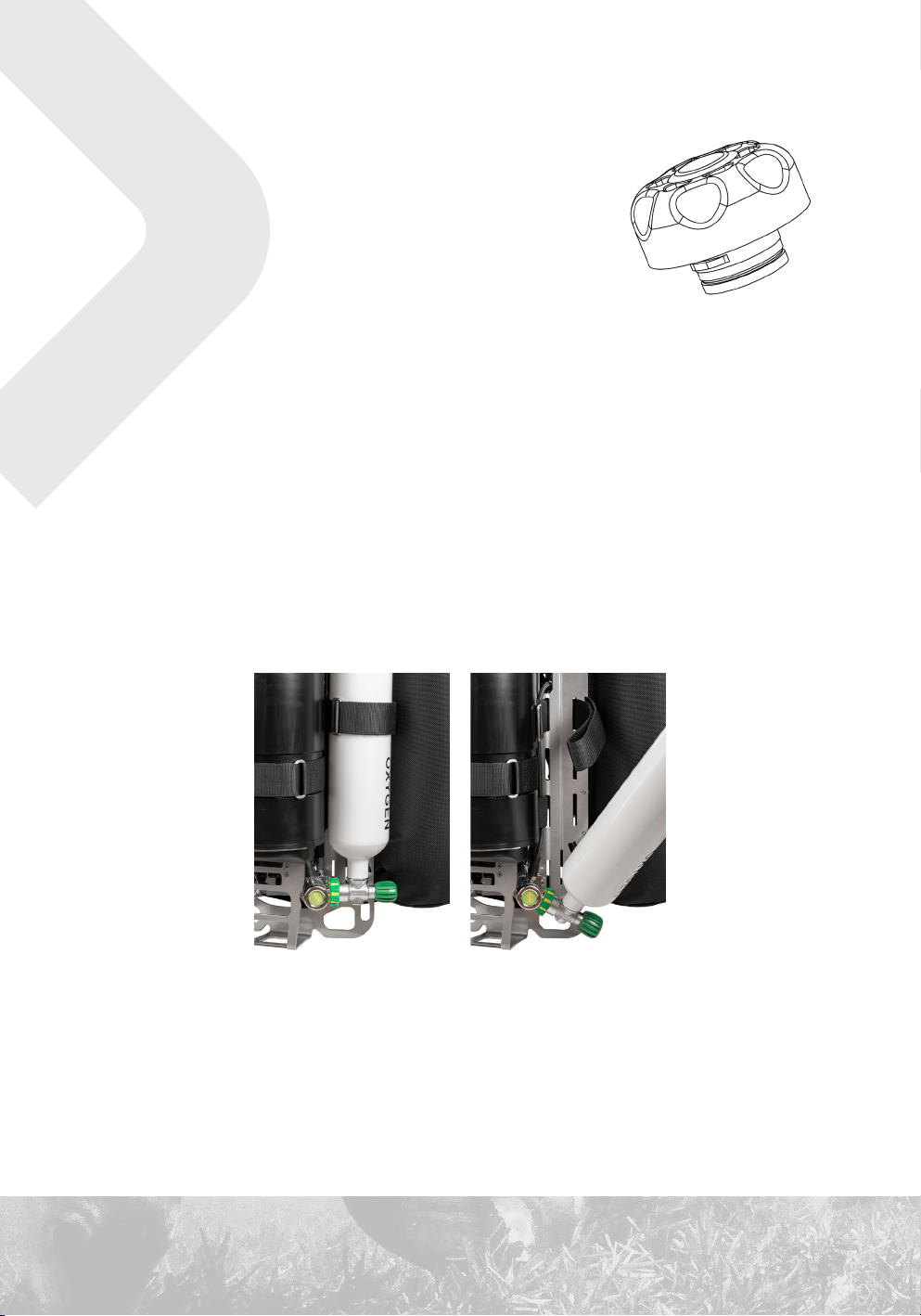
When connecting the oxygen tank to the unit screw in the hand wheel only when the tank is
upright. If you straighten the bottle when it is screwed in you will tighten the threads to the
point when it will be hard to remove without the usage of tools
For more information on filling, see 73 Oxygen.
1.6.2 Valve
The valve has a M26×2 200 bar outlet connection. The valve is not compatible with standard
DIN valves to eliminate possible mix-up between oxygen and diluent bottles, this is
a requirement of the EN 14141 norm.
1.6.3 Reduction valve
The CCR Liberty uses an Apeks DST4 first-stage regulator with a specially made low-pressure
turret, which is mounted on the backplate. This serves as the lower tank-mounting point; in the
middle part, the tank is attached with a Velcro strap.
The Apeks DST4 first-stage regulator comes with an environmentally sealed first-stage kit.
This seal causes an operational limitation at a depth of 170 meters. It is recommended that in
order to conduct dives beyond 170 meters the diver must replace the first-stage regulator with
the Apeks UST4 environmentally unsealed kit.
The reduction valve is equipped with an intermediate-pressure safety overpressure valve.
1.6.4 Pressure reading
The oxygen pressure gauge is situated on the right side; the HP hose runs through an opening in
the backplate.
1.7 Diluent tank
1.7. 1 Tank
The CCR Liberty uses a three-liter steel tank with 100 mm diameter and 230 bar filling
pressure. The original 300 bar filling pressure of the bare tank was changed because a 230 bar
valve is used.
The tank is labeled DILUENT.
19
The tank is situated on the left from the diver’s perspective when wearing the CCR Liberty.
For more information on filling, see 72 Diluent.
1.7. 2 Valve
The valve has a DIN G 5/8” 230 bar outlet connection.
1.7.3 Reduction valve and pressure reading
The design is similar to that of the oxygen tank, only reversed.
1.7. 4 Backup regulator (optional)
The second stage of a regulator may be connected to the output of the first stage of the
diluent through LP hose of appropriate length. This regulator can be used as a backup if the
diluent at a given depth is breathable (oxygen partial pressure between 0.16 and 1.6 bars).
Having the backup regulator connected to the diluent may be useful for sanity breaths and for
prolonged switching to a backup apparatus.
However, it is advised to use the bailout only in special circumstances, for example during
extreme shallow dives.
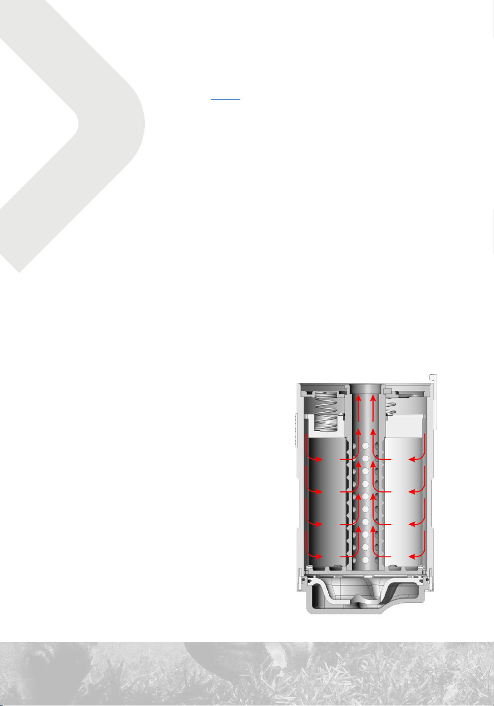
1.8 CO2 scrubber
The CCR Liberty uses a radial scrubber. The breathing
mixture flows from the outside to the center of the
scrubber cartridge.
The scrubber consists of a scrubber cartridge inserted
into a scrubber canister. A water trap is situated in the
lower part of the canister.
The walls of the cartridges consist of external and
internal metal mesh. A lid presses down on the scrubber
cartridge by means of springs attached to the pressure
plate. The pressure plate is fastened to the central tube
with a retaining ring.
20
The scrubber cartridge capacity is
approximately 2.5 kg of sorbent. The
sorbent volume is approximately
2.82-2.99 l.
The service life and replacement of
the sorbent are described in chapter
66 Replacement of CO2 sorbent.
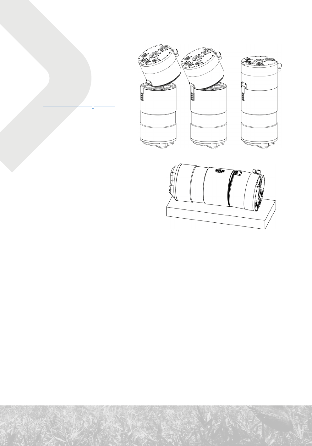
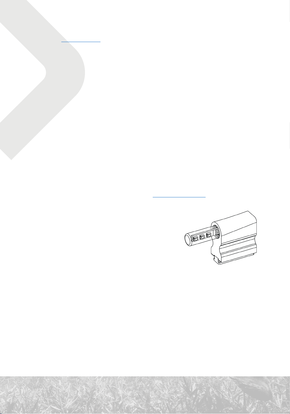
1.9 Head
The head is mounted on the CO2
scrubber canister.
When mounting the head, push the
scrubber-canister pin into the opening on
the head and close it.
If it is difficult to remove the head, place
the rebreather on a hard surface with the
pin facing downwards, as shown in the
illustration. Press down on the head and the scrubber canister with your hands.
1.9.1 Control units
The control units (hereinafter referred to as the CUs) are independent. A display unit (hereinafter referred to as the HS) is connected to each CU, which each has its own power source, solenoid, temperature gauge and pressure, O2 partial pressure and He concentration sensors.
If one control unit fails, the other control unit takes over automatically.
CUs and HSs are independent computers communicating via a bus. Each handset displays the results of both CU’s activities and is used to control both CUs. Each HS is powered through the corresponding CU. In the event of a malfunction of both handsets, either CUs (or the remaining functional CU) will continue to regulate ppO2 without change according to the last adjusted setpoint.
If communication between CUs breaks down, each unit controls one solenoid. The control
algorithm is sufficiently robust to ensure that any deviations of ppO2 from the allowed limits
will not occur during dual, parallel regulation.
21

Connection to a personal computer
The memory of operating protocols and content of the memory card can be read using a USB
adapter connected to the handset connector as a mass storage device (like a flash drive). The
connection to Windows, Mac, Linux, Android and iOS was tested, but there is no guarantee of
compatibility with all operating systems and all computers.
During the time of USB connection, the control unit is powered from the USB port and, at the
same time, the battery is charged.
Each control unit contains the same dive logs, to download them you only need to connect one
control unit to the computer.
1.9.2 Direct measurement of ppO
To measure ppO2 use only DIVESOFT R22D-type sensors. The usage of other sensors from other
manufacturers is prohibited.
Two sensors are connected to each CU. All sensors are located on the inhalation side. Both CU
have access to all four oxygen sensors as the control units continually exchange the measured
data.
The diver can manually exclude a sensor from operation and manually return an excluded
sensor to averaging. The manual option has a higher priority than automatic detection of faulty
sensors. If all sensors are excluded, the CCR Liberty can be switched to a backup algorithm for
calculation of the partial pressure of oxygen indirectly using measurement of the He content
(assuming the used diluent contains >20% He).
Circulation of the mixture in the breathing loop is necessary for the measurement accuracy. If
the user does not breathe from the rebreather, the mixture in the vicinity of the oxygen sensors
can have a different proportion of oxygen than the mixture in different parts of the breathing
loop and the displayed data can thus be inaccurate.
A discrepancy can similarly occur in the event of rapid descent, when a larger amount of
diluent is added, or when the setpoint is changed to high and ppO2 in the loop is changing to the
new level
2
The sensors are constantly automatically evaluated. The ppO2 measured by one sensor is
always compared to average of the other sensor. This way each individual sensor is constantly
being cross-checked and monitored for possible deviations. If the average deviation of the
22
sensors from the diameter exceeds 0.1 bar, the sensor that deviates most from the average is
automatically excluded.
Only one sensor can be automatically excluded at the same time, and the maximum number
of automatically excluded sensors is 2. There will always be at least two sensors that the
diver has to evaluate by themselves. This procedure is described in Chapter 3.4.4 Monitoring of
devices.
WARNING: Sensor exclusion works on the principle of a mathematical algorithm. Despite the
efforts of developers to find the ideal risk-control solution, there is still a chance that the
excluded sensor will only be the only right one. Always verify your oxygen sensors.
Refer to the chapter “Oxygen sensors” on how to handle and maintain your sensors.
1.9.3 Measurement of He content
The helium concentration is determined by the velocity of sound in the mixture. The He
concentration sensors are connected to the inhalation side.
A pressure drop caused by circulation of the mixture in the breathing
loop allows the mixture to pass through the sensor. If the user does
not breathe from the rebreather, this will not occur and sensor
reading may be inaccurate.
If the utilized diluent contains >20% He and its composition is known,
the He-concentration measuring function can be used for reverse
determination of the concentration of oxygen in the mixture based
on the fact that the ratio of inert gases remains constant (process
according to patent no. 303577). This principle of measuring the
oxygen concentration (and its subsequent automatic conversion on
the basis of the known ambient pressure to partial pressure) is used as the backup method of
measuring ppO2 in case all electrochemical ppO2 sensors malfunction.
Oxygen measuring using helium sensors must be manually turned on in Setup / Faulty sensors
/ pO2 source. This method is intended for use only in emergency situations. If possible, use
bailout apparatus.
The use of helium sensors also depends on Liberty’s settings. For the helium sensor function,
the “TMX only” must be set in Menu / Setup / Preferences / He Measurement.
23

For proper functioning of helium sensors, the sensors must be calibrated from time to time.
Refer to Calibrating Helium Sensors for the calibration procedure
Always keep your helium sensors dry to ensure their long lifetime and functionality (see
also 92 – 3.5.1 Immediately after surfacing).
Do not disassemble the sensors; disassembly can result in irreparable damage.
WARNING: Do not remove the helium sensors from the unit, even when faulty. Their removal
will “short -circuit” the scrubber, which won’t be able to filter CO2 from the breathing mixture.
1.9.4 Pressure and depth measurement
Each of the CCR Liberty’s control units uses dual pressure sensors. The first sensor, intended
for measuring low pressure, is used for determining sea level, for calibration of the ppO2
sensors, and for improving the accuracy of depth data in shallow depth.
The second sensor is intended mainly for measuring hydrostatic pressure. The maximum scope
of the sensor corresponds to the depth of 300 m.
1.9.5 Temperature measurement
The temperature in the breathing circuit is measured by temperature sensors within the
pressure sensors. The water temperature sensors are situated in the handsets.
Temperature data serve primarily for correction of the measuring of other quantities. The water
temperature shown on the HS display is only approximate.
1.9.6 Solenoids
The control units communicate with each other and, in normal circumstances, open the
solenoid valves, which supply oxygen to the breathing circuit.
The solenoids are opened alternately left – right in the interval of 6 s. The solenoid opening is
indicated in the dive mode by the equator in the left or right bottom corner of the handset screen.
1.9.7 Power supply
CCR Liberty uses two Li-Ion batteries, one to power each control unit. The minimum service life
of Li-Ion batteries is six months. The typical service life of the batteries is two years.
24
See also 74 Battery charging.
Battery compartments are pressure resistant. If overpressure is formed inside a battery
compartment because of battery malfunction or helium diffusion, then an overpressure valve
will release excess gases out of the rebreather and into the surrounding water.
1.10 Visual display units
1.10.1 Handsets
The handsets provide the CCR Liberty’s user with comprehensive information on the
rebreather’s status and the course of the dive. All functions of the control units are controlled
using the handsets.
The functionality of both handsets is identical. Each handset controls both CUs simultaneously.
In the event of a malfunction of one handset, the diver simply uses the other handset. During
a dive, it is possible to set a different display mode on each handset.
For more information on handset operation, see 31 Control-unit operation.
1.10.2 Head-up display
The head-up display (HUD) shows the current partial
pressure or CCR error status during the dive.
Other statuses are displayed in standby mode, during
charging and when the unit is connected to a computer.
If you are not entirely sure what the HUD is displaying, check the parameters on the handset
display. Always check it if the HUD displays a warning (outer LED blinks red) or an alarm (all
three LEDs flashes red four times).
See the following table for the various HUD signals.
1.10.3 Buddy display
The buddy display shows whether the values of the partial pressure of oxygen are within
the range that is suitable for breathing or if an error situation has occurred. The displayed
information is intended for the diving partner of the CCR Liberty’s user.
25

Prior to diving, the user of the CCR Liberty must familiarize his/her diving partner with the
buddy display’s functionality and agree on the emergency procedure to be carried out in the
event that the buddy display indicates an error situation.
See the following table for the various buddy-display signals.
HUD and buddy-display signals
Mode Event / state
Startup
Initializing
components
ppO2 < 0.16 • red blinking • red blinking • red blinking
0.16 ≤ ppO2 < 0.20 • red blinking • red blinking • red
0.20 ≤ ppO2 < 0.25 • red blinking • red blinking • green
0.3 • 7× blue flash • green
0.4 • 6× blue flash • green
0.5 • 5× blue flash • green
0.6 • 4× blue flash • green
0.7 • 3× blue flash • green
ppO
2
in dive mode
1
(bar; standard)
0.8 • 2× blue flash • green
0.9 • 1× blue flash • green
1.0 • green • green
1.1 • 1× green flash • green
1.2 • 2× green flash • green
1.3 • 3× green flash • green
1.4 • 4× green flash • green
1.5 • 5× green flash • green
1.6 • 6× green flash • green
1.65 < ppO2 ≤ 2.0 • red blinking • red blinking • red
ppO2 > 2.0 • red blinking • red blinking • red blinking
Dive mode alarm • 4× red flash • 4× red flash • 4× red flash no change
Standby • slowly flashing
Charging • 1. red • 2. red • 3. red • red
Standby (switched
off from menu)
Charger connected
but no power
supply
Fully charged • green • green • green • green
Charging failed • red blinking • red blinking • red blinking • red blinking
Mass storage
mode (USB adaptor
connected)
Download firmware
Reading • green • orange • green
Writing • red • orange • red intensive
No action • orange
Connected • purple • purple blinking • purple
Downloading • purple • purple
HUD signals
LED 1 LED 2 LED 3
BD signals
Binary coded service numbers
• slowly
flashing
• red blinking • red blinking
1
Indicated ppO2 value in the range ±0.05 bar
26
Color blind mode
If you cannot distinguish blue and green LED lights, check “Color blind mode” in Setup
→ Preferences → Indication. Signals for 1.05 ≤ ppO2 ≤ 1.65 will be changed according the
following table:
1.1 • 1× green flash • 1× green flash
1.2 • 2× green flash • 2× green flash
ppO2 in dive mode
(bar; color blind)
1
Indicated ppO2 value in the range ±0.05 bar
1
1.3 • 3× green flash • 3× green flash
1.4 • 4× green flash • 4× green flash
1.5 • 5× green flash • 5× green flash
1.6 • 6× green flash • 6× green flash
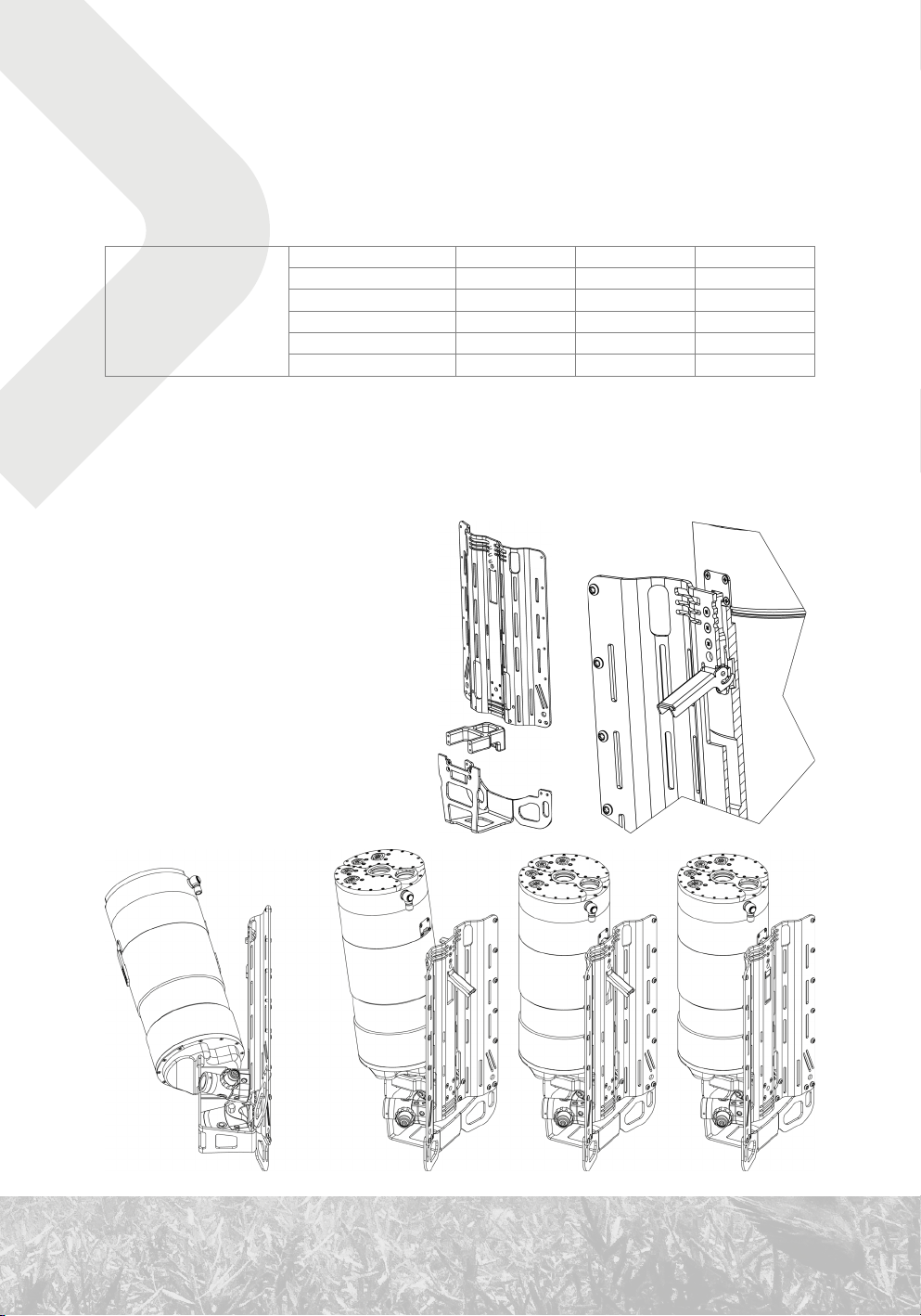
1.11 Backplate and mounting
The method of mounting the CCR Liberty
on the diver’s body is based on the
backplate and harness common among
wing-type buoyancy compensators used
in technical diving.
The body of the rebreather, comprised of
the scrubber canister and attached head,
is attached to the backplate with a cam.
The cam lever cannot be released when
the diver is wearing the rebreather.
27

The CCR Liberty’s integrated stand, which serves as a lumbar support, is intended for setting
the rebreather on a hard, level surface with sufficient rigidity. Always secure the standing
rebreather to prevent falling.
If needed, it is possible to remove the CCR Liberty’s backplate, together with the buoyancy
compensator from the components specific for the rebreather and use it with the harness
for open-circuit diving. It enables attachment of a twin-set (two tanks firmly connected with
stainless steel bands) using bolts and wing nuts as is common in technical diving, as well as
attachment of a single tank with a strap with fastener (not included with the CCR Liberty).
When mounting the CCR Liberty onto the backplate, set the bottom of the scrubber cannister
into the protrusion in the rebreather stand.
1.12 Harness
The backplate is equipped with harness that is threaded through in a way that ensures proper
system functioning. Do not change the way it is made. If you do try to take the harness out,
record or remember exactly how it is threaded through to prevent interference with the
functioning of the whole system.
It is necessary to adjust the harness so that it fits properly. Adjust the harness without the
mounted scrubber canister, head, corrugated hoses and breathing bags.
Adjust the length of the shoulder straps so that it is possible to insert three fingers under the
straps at the collar-bone level without great resistance but not entirely freely.
The chest D-rings should be as low as possible, while still allowing you to cross your arms over
your chest comfortably. The D-rings should be high enough for you to reach the left ring with
your left thumb, and the right ring with your right thumb. The D-ring on the left side of the
waist strap should be roughly on your hip.
Adjust the length of the left part of the belt strap so that it passes through the eye of the
crotch strap and there is approximately 5 cm (strap width) between the ring and the eye. Adjust
the right part so that the strap is slightly tight. If you shorten a strap, leave sufficient reserve
for different suits and possible change of body dimensions. After shortening, it is necessary to
deburr the ends of the straps by heat sealing them with a cigarette lighter or candle. Do this
carefully so as not to form a hard surface on the strap ends.
28

Adjust the length of the crotch strap so that it passes closely to the body but does not
bind. Set the position of the rear D-ring as low as possible but sufficiently high so that it
does not place pressure on the buttocks when swimming. The rear D-ring should be within
the diver’s reach. Test the exact position of the rear D-ring in the water with the complete
apparatus.
1.13 Buoyancy compensator
The CCR Liberty uses a wing-type buoyancy compensator (BCD) with displacement of 200 N.
The compensator’s design and materials are very durable and even suitable for cave and wreck
diving.
The wing has a two-ply design. The internal bladder is made of high-frequency-welded Cordura
560 fabric with PU coating. The wing’s external cover is made of Cordura 2000 fabric.
The wing is attached with screws along the edge of the backplate.
To achieve the correct position of the inflator, pass the low-pressure hose through the rubber
ring on the corrugated hose, then through the rubber ring on the shoulder strap and finally
through the second rubber ring on the corrugated hose. Do not skip either of the rings on the
corrugated hose; upon disconnecting the quick-release connector from the inflator, it could
recede so far that it would be difficult to find it.
The buoyancy compensator is not a life preserver. It does not maintain the diver in a face-up
position. It is not designed to hold the diver’s face above the surface should he/she become
unconscious or immobile.
1.14 Ballast
The ballast system is composed of two pouches placed on the sides of the scrubber canister
and is attached to the tanks. In the lower part of the pouches, there is a loop through which
the attachment strap of the rebreather body is passed. The internal pouches, which contain
the individual weights, are inserted into the external pouches. The upper flap of the external
pouch is intended for inserting weights before a dive and removing them after. For emergency
jettisoning of ballast, pull the red strap on the lower part of the pouch. This will open the
external pouch and will release the internal pouch containing the ballast.
29
 Loading...