

Page 1
Operation and Maintenance Manual
Quick Start
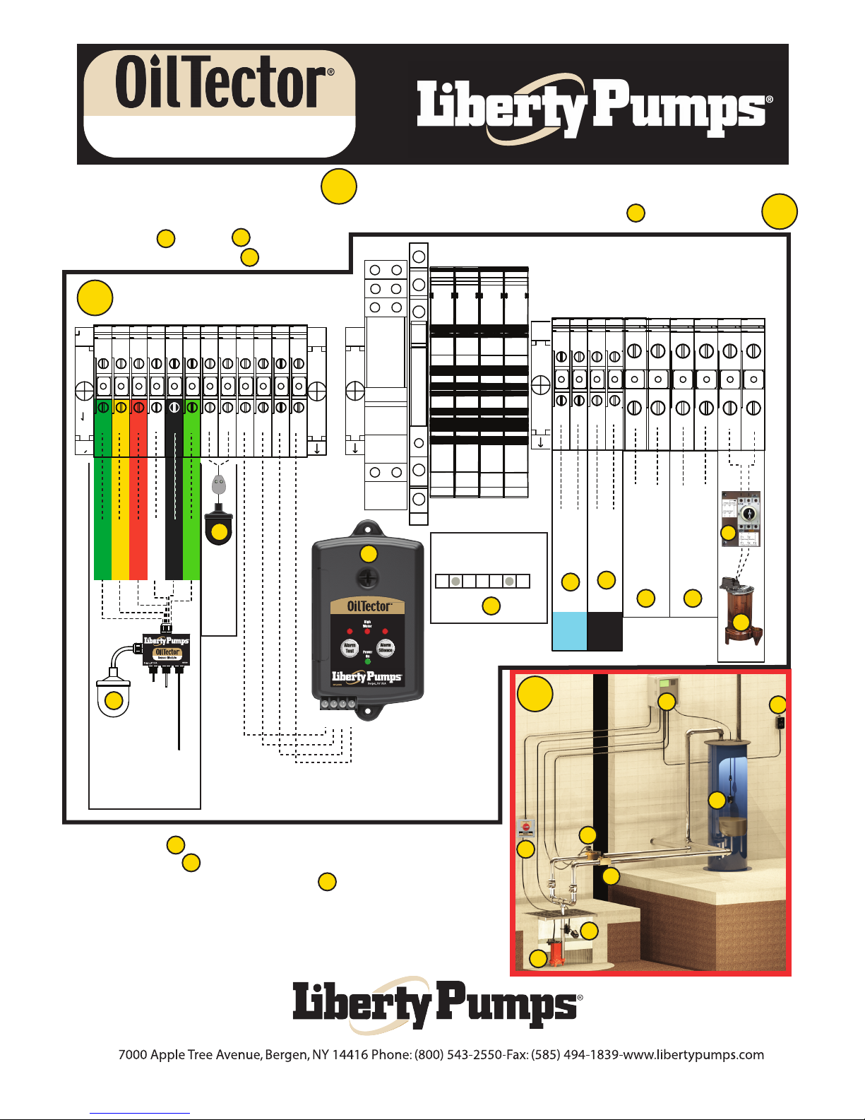
1 Phase Simplex Auto-Valve
Use the (Installation Example) diagram on the bottom right of this page as a reference to match up each
1
component included in this system to the correct terminal blocks inside the control panel shown in diagram
Follow steps through on this page
3
and in order. Note for step on bottom.
11
8
A
2
2
1 2 3 4 5 6 7 8
Red
White
Green
Yellow
3
Black
Shield
Preset Level
Sensor Mounted
In Sump
4
Float Switch
Holding Tank
C 1 2 3
5
Holding Tank
High
High Level
Oil
C 1 2 3
Remote Alarm
Mounted Indoors & Provides Audible
& Visual Alarm
Connect all ground wires
for steps 6-10 to the
ground bar
11
1
9 10 11
SV1
Rated
6
Water
Valve
SV2
120 VAC
Oil
Valve
12
7
Rated
120 VAC
N
L1
Incoming
Control
Power
From
Breaker
Box
120V
9 10
L1
Incoming
Pump
Power
From
Breaker
Box
120/230V
A
L2/N
T1
B
Pump
4
T2
8
5
Note: The pump is wired to the bottom of the disconnect switch
in the junction box then the top of the disconnect switch in the
8
B
junction box is wired to the control panel
Terminals T1 & T2.
A
B
6
7
3
Installation
Example
8
Page 1 of 3
Manual 6963000A
DWG# 6963000A
Page 2
Operation and Maintenance Manual
Quick Start
1 Phase Simplex Auto-Valve
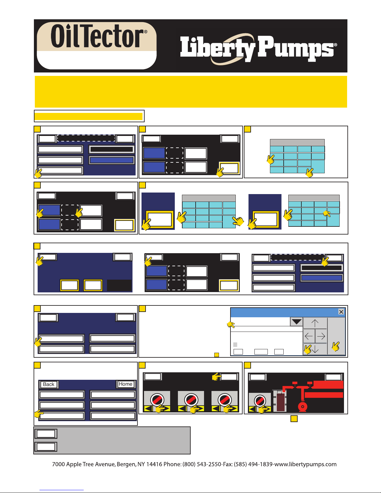
QUICK START
USE PAGE 2 FOR ROUND SHAPED HOLDING TANKS (Follow Steps A-O)
USE PAGE 3 FOR RECTANGLE OR SQUARE SHAPED HOLDING TANKS (Follow Steps A-O)
A.Turn On Power To The Control Panel
B. Press (Configure Oil Tank)
B C
Home
Pump Elapsed Time
B
E
Back
E1
Rectangle
G1. Press (Back) Button On Round Tank Screen G2. Press (Back) On Select Oil Storage Tank Screen G3. Press (Next) On Todays Date Screen
G
Back
G1
H. Press (Maintenance Menu) Button
H
Back
Maintenance Menu
H
Input/Output Status
Press Pump / Valve To Verify Position Of Switches.
J
Note: Off Delay Is Preset To 10 Seconds.
Pump Off-Delay Time
J
Pump / Valve Control
Back
Todays Date & Time Display
Pump Run Count
Configure Oil Tank
E1. Press (Round Tank)
E2. Press (Round Dimensions)
Select Oil Storage Tank Type &
Enter Dimensions and GPM.
Round
Tank
Tank
Dimensions
E2
Rectangle
Dimensions
Round
Round
Next
Alarms
Rest Faults
Home
Enter
Pump GPM
1 2 3
Home
Tank Dimensions
Diameter
Inches
1 2 . 3 1 2 . 3
Menu #2 Screen
Back
Maint. Punch Clock
Maintenance Screen
Depth
Inches
Total Tank
Gallons
1234.5
Set Date / Time
Screen Contrast
Reset Fault Counters
Reset Pump Counters
Reset Data Log
Home
Home
Will Always Take You To The Previous Screen
C. Press (Enter Pump GPM)
Select Oil Storage Tank Type &
Back
Rectangle
F
Enter Dimensions and GPM.
Round
Tank
Tank
F1. Press(Diameter Inches) Button. F2. Enter Oil Tank Diameter. Press ENT. Repeat For Depth.
Round
Dimensions
Rectangle
Dimensions
Diameter
Inches
1 2 . 3
F1
Select Oil Storage Tank Type &
Back
G2
Rectangle
I1. Enter Password (1001) as shown below.
I
I2. Press Arrow Keys Until 1 Is Highlighted
I3. Press ENT (1st * appears)
I2. Press Arrow Keys Until 0 Is Highlighted
I3. Press ENT (2nd * appears)
I2. Press Arrow Keys Until 0 Is Highlighted
I3. Press ENT (3rd * appears)
I2. Press Arrow Keys Until 1 Is Highlighted
I3. Press ENT (4th * appears)
I2. Press Arrow Keys Until OK Is Highlighted
I3. Press ENT (You Will Be On Screen )
N1. Place All Switches In Auto
N
N2. Press Home Button
Back
Hand Auto
Enter Dimensions and GPM.
Round
Tank
Tank
Pump
7 8 9 CLR
4 5 6 CAN
1 2 3
F2
+ / -0.
Round
Dimensions
Rectangle
Dimensions
Sol. Valve #1
Hand-Off-Auto
Home
Enter
Pump GPM
1 2 3
C
1 2 3 4 5 6 7 8 9 0
ENT
Home
Enter
Pump GPM
1 2 3
I1
J
Home
N2
Sol. Valve #2
Hand-Off-Auto
Password
Level 1
****
ABCDEFGHIJKLM
NOPQRSTUVWXYZ
0 1 2 3 4 5 6 7 8 9
BS
H A H A H A
N1
N1
N1
D1. Enter Pump Gallons Per Minute From Pump Nameplate.
D
D2. Press ENT
1 2 3 4 5 6 7 8 9 0
7 8 9 CLR
4 5 6 CAN
D1
1 2 3
0
Depth
Inches
1 2 . 3
F2
Home
Pump Elapsed Time
CLR OK
Place Pump HOA’S into Auto Mode And Do The
O
Bucket Test
Menu
Pump
Off Auto
H A
After completeing step you have finished the
quick start and are on the Home Screen
Todays Date & Time Display
Pump Run Count
Configure Oil Tank
(See Page 20 Of Main Manual)
Home Screen
O1
.
+ / -
D2
1 2 3 4 5 6 7 8 9 0
7 8 9 CLR
4 5 6 CAN
1 2 3
+ / -0.
Rest Faults
I2
P
SV-1
SV-2
Pump Failed
O
ENT
ENT
Next
G3
Alarms
ENT
Alarms
Power Loss
I3
Home
Will Always Take You To The Home Screen
Page 2 of 3
Manual 6963000A
DWG# 6963000A
Page 3

Operation and Maintenance Manual
Quick Start
1 Phase Simplex Auto-Valve
QUICK START - FOLLOW STEPS A-O IF USING A SQUARE OR RECTANGLE TANK
A.Turn On Power To The Control Panel
B. Press (Configure Oil Tank)
B C
Home
Pump Elapsed Time
B
E
Back
Rectangle
E1
G1. Press (Back) Button On Square/Rectangle Screen G2. Press (Back) On Select Oil Storage Tank Screen G3. Press (Next) On Todays Date Screen
G
Back
G1
1 2 . 3 1 2 . 3
H
Maintenance Menu
H
Input/Output Status
Press Pump / Valve To Verify Position Of Switches.
J
Note: Off Delay Is Preset To 10 Seconds.
Pump Off-Delay Time
J
Pump / Valve Control
Back
Todays Date & Time Display
Alarms
Pump Run Count
Configure Oil Tank
E1. Press (Rectangle Tank)
E2. Press (Rectangle Dimensions)
Select Oil Storage Tank Type &
Enter Dimensions and GPM.
Round
Tank
Tank
Dimensions
Dimensions
E2
Rest Faults
Round
Rectangle
Square / Rectangle
Tank Dimensions
Length
Inches
Width
Inches
1 2 . 3
H. Press (Maintenance Menu) Button
Back
Back
Maint. Punch Clock
Menu #2 Screen
Maintenance Screen
Depth
Inches
1234.5
Set Date / Time
Screen Contrast
Reset Fault Counters
Reset Pump Counters
Reset Data Log
Will Always Take You To The Previous Screen
Next
Home
Enter
Pump GPM
1 2 3
Home
Total Tank
Gallons
Home
Home
C. Press (Enter Pump GPM)
Select Oil Storage Tank Type &
Back
Round
Rectangle
F1. Press(Length Inches) Button. F2. Enter Length. Press ENT. Repeat For Width & Depth.
F
Enter Dimensions and GPM.
Tank
Tank
Round
Dimensions
Rectangle
Dimensions
Length
Inches
7 8 9 CLR
Home
Enter
Pump GPM
1 2 3
C
1 2 3 4 5 6 7 8 9 0
4 5 6 CAN
1 2 3
1 2 . 3
F1
Back
G2
Round
Tank
Rectangle
Tank
I1. Enter Password (1001) as shown below.
I
I2. Press Arrow Keys Until 1 Is Highlighted
I3. Press ENT (1st * appears)
I2. Press Arrow Keys Until 0 Is Highlighted
I3. Press ENT (2nd * appears)
I2. Press Arrow Keys Until 0 Is Highlighted
I3. Press ENT (3rd * appears)
I2. Press Arrow Keys Until 1 Is Highlighted
I3. Press ENT (4th * appears)
I2. Press Arrow Keys Until OK Is Highlighted
I3. Press ENT (You Will Be On Screen )
N1. Place All Switches In Auto
N
N2. Press Home Button
F2
+ / -0.
Select Oil Storage Tank Type &
Enter Dimensions and GPM.
Round
Dimensions
Rectangle
Dimensions
Back
Pump
Hand Auto
Sol. Valve #1
Hand-Off-Auto
H A H A H A
N1
N1
ENT
Home
Enter
Pump GPM
1 2 3
Password
Level 1
I1
ABCDEFGHIJKLM
NOPQRSTUVWXYZ
0 1 2 3 4 5 6 7 8 9
J
Home
N2
Sol. Valve #2
Hand-Off-Auto
N1
****
BS
D1. Enter Pump Gallons Per Minute From Pump Nameplate.
D
D2. Press ENT
1 2 3 4 5 6 7 8 9 0
7 8 9 CLR
4 5 6 CAN
D1
1 2 3
0
Width
Inches
1 2 . 3
F2
Home
Pump Elapsed Time
CLR OK
Place Pump HOA’S into Auto Mode And Do The
O
Bucket Test
Menu
Pump
Off Auto
H A
After completeing step you have finished the
quick start and are on the Home Screen
Todays Date & Time Display
Pump Run Count
Configure Oil Tank
(See Main Manual)
Home Screen
O1
+ / -
P
SV-2
O
.
D2
Depth
Inches
1 2 . 3
Rest Faults
I2
SV-1
Pump Failed
ENT
Next
G3
Alarms
ENT
Alarms
Power Loss
I3
Home
Will Always Take You To The Home Screen
Page 3 of 3
Manual 6963000A
DWG# 6963000A
 Loading...