

Page 1
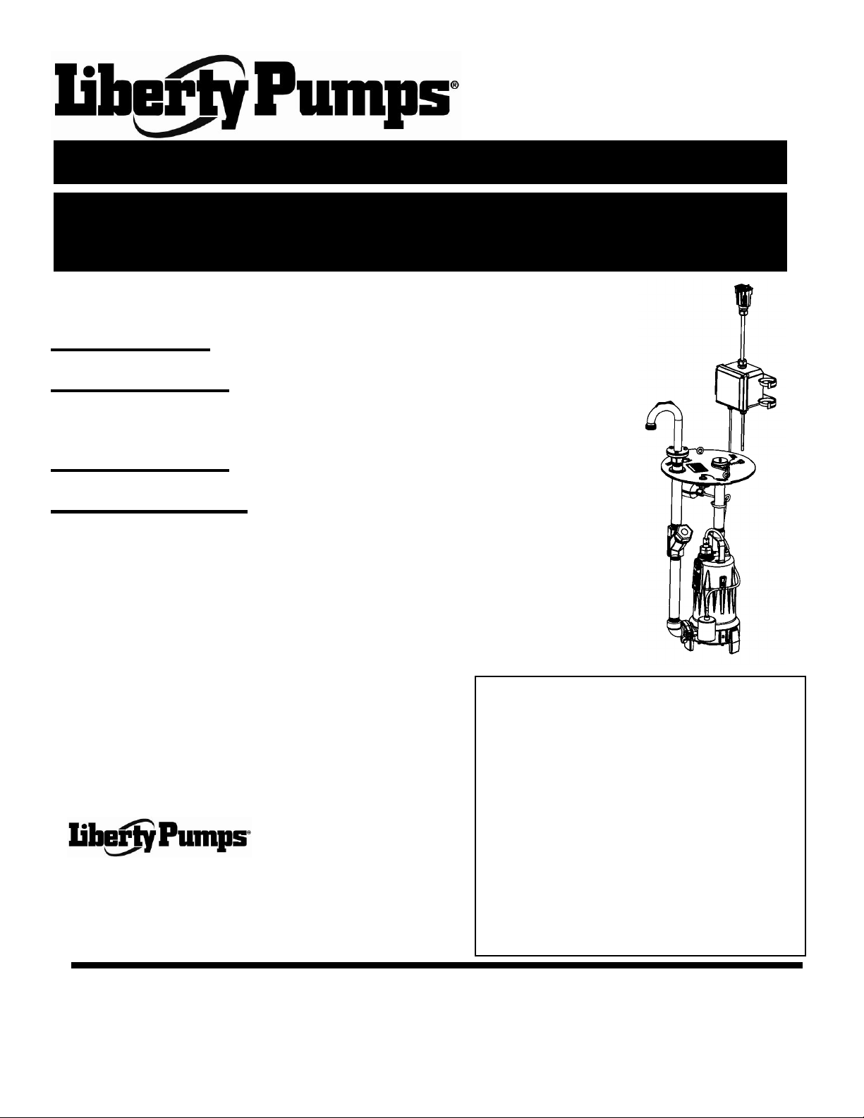
RE/REX Series Installation Manual
5672000H
Omnivore Grinder Pump Retrofit Unit
For E/One* GP200, GP2000 and EXTREME D-Series
IMPORTANT:
Prior to installation, record Model, Serial
Number, and Code Number from pump
nameplate for future reference.
MODEL _____________________
SERIAL _____________________
CODE _____________________
INSTALLATION
DATE _____________________
7000 Apple Tree Avenue
Bergen, NY 14416
Phone: (800) 543-2550
Fax: (585) 494-1839
www.libertypumps.com
Core replacement for GP200 and GP2000:
LSG202-RE 2Hp, 208/230V, 1 phase, Automatic
LSGX202-RE 2Hp, 208-230V, 1 phase, Automatic
Core replacement for Extreme D-Series:
LSG202-REX 2Hp, 208/230V, 1 phase, Automatic
LSGX202-REX 2Hp, 208-230V, 1 phase, Automatic
*Do not throw away or lose this manual. Keep it with the installation
and refer to it often.
* E-One is a registered Trademark of Environment One Corporation and is not affiliated with Liberty Pumps.
©Copyright 2012 Liberty Pumps Inc. All rights reserved - 1 -
Page 2

TABLE OF CONTENTS
SECTION 1 GENERAL INFORMATION------------------------------------------------------------------------------ 3
SECTION 2 INTRODUCTION-------------------------------------------------------------------------------------------- 4
SECTION 3 INSTALLATION ------------------------------------------------------------------------------------------- 4-6
SECTION 4 OPERATION -------------------------------------------------------------------------------------------------7
TROUBLESHOOTING CHART ------------------------------------------------------------------------ 9
PANEL INSTALLATION SHEET----------------------------------------------------------------------- 10
SECTION 5 WARRANTY INFORMATION--------------------------------------------------------------------------- 11
©Copyright 2012 Liberty Pumps Inc. All rights reserved - 2 -
Page 3
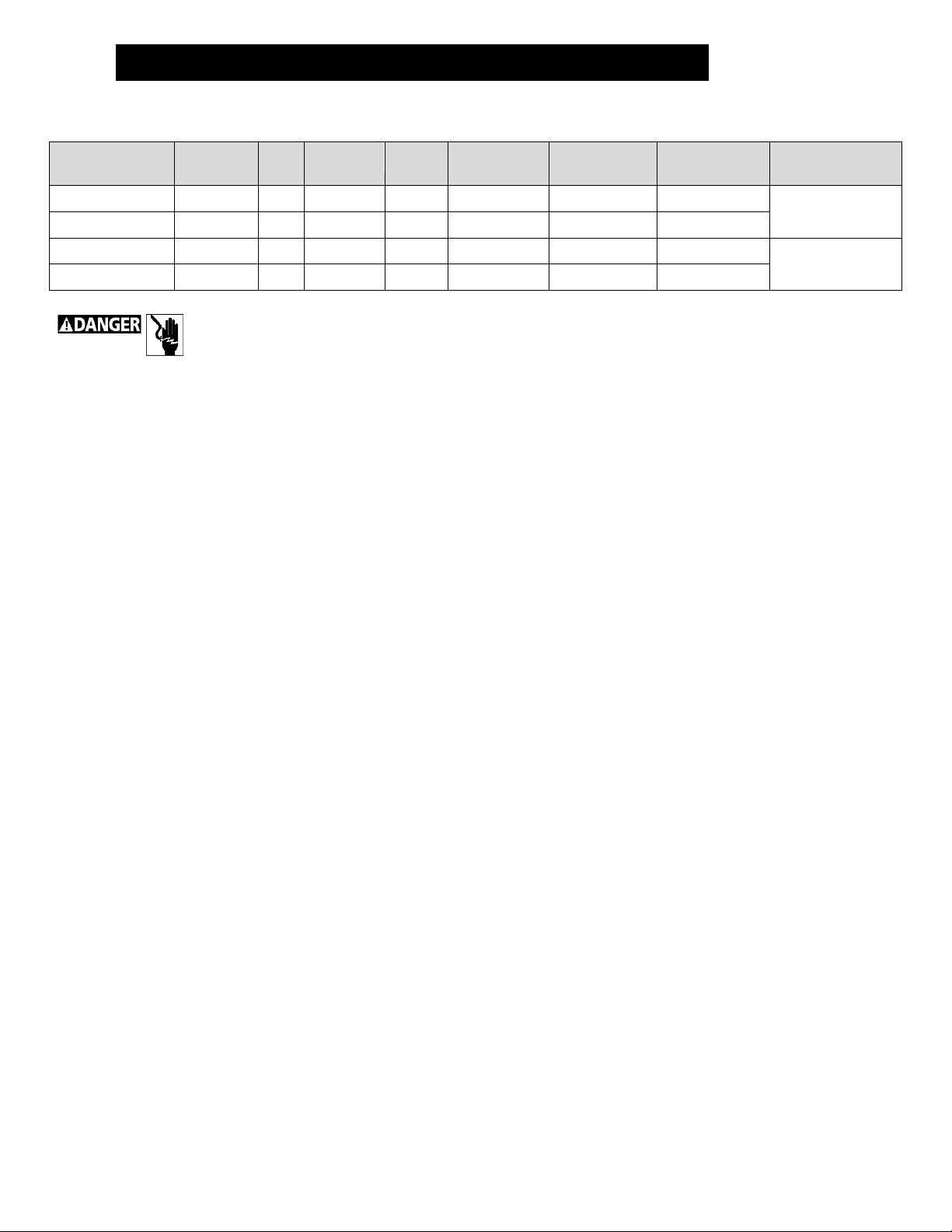
Model
Type
HP
Volts
Phase
Full Load
Amps
FNPT
Discharge
Automatic or
Manual*
Drop in
replacement for
LSG202-RE
1 Stage
2
208\230
1
15
1.25”
Automatic
GP200 OR
GR2000
LSGX202-RE
2 Stage
2
208-230
1
15
1.25”
Automatic
LSG202-REX
1 Stage
2
208\230
1
15
1.25”
Automatic
EXTREME OR
D-SERIES
LSGX202-REX
2 Stage
2
208-230
1
15
1.25”
Automatic
1.
General Information – All Models
Before installation, read the following instructions carefully. Each Liberty pump is individually factory tested to ensure proper
performance. Closely following these instructions will eliminate potential operating problems, assuring years of trouble-free service.
Risk of electric shock.
Note: Make sure the electrical specifications of the control selected properly match the electrical specifications of the
pump. Always refer to control panel instructions for proper installation. A separate branch circuit is recommended. It must
be sized in accordance with the National electric code for the current shown on the pump nameplate and literature.
Risk of electric shock. Always disconnect the pump from the power source before handling or making adjustments.
The electrical connections and wiring for a pump installation should only be made by qualified personnel.
This pump is supplied with a grounding conductor and grounding-type attachment plug. To reduce the risk of electric
shock, be certain that it is connected only to a properly grounded, grounding-type receptacle.
DO NOT bypass grounding wires or remove ground prong from attachment plugs.
DO NOT use an extension cord.
This pump requires a separate, properly fused and grounded branch circuit. Make sure the power source is properly
sized for the voltage and amperage requirements of the pump, as noted on the nameplate.
The electrical outlet shall be within the length limitations of the pump power cord, and at least 4 feet above floor level
to minimize possible hazards from flood conditions.
The installation must be in accordance with the National Electric Code, Uniform Plumbing Code, International
Plumbing Code, as well as all applicable local codes and ordinances.
Sump and sewage pumps often handle materials which could cause illness or disease. Wear adequate protective
clothing when working on a used pump or piping.
Never enter a pump basin after it has been used. Sewage and effluent can emit several gases which are poisonous.
Keep clear of suction and discharge openings. To prevent injury, never insert fingers into pump while it is plugged in.
DO NOT use this product for flammable or corrosive liquid.
DO NOT use this product in applications where human contact with the pumped fluid is common (such as swimming
pools, fountains, etc.)
NEVER dispose of materials such as paint thinner or other chemicals down drains, as they can chemically attack and
damage pump components, potentially causing product malfunction or failure.
DO NOT use pumps in water over 140F (60C).
DO review applicable codes concerning maximum allowable temperature of water discharged into drain systems.
DO NOT use pumps in mud, sand, cement, oil or chemicals.
DO NOT modify the pump in any way.
DO NOT lift or carry pump by power cord.
DO NOT remove any tags from pump or cords.
If pump is installed during construction before power is available, it must be protected from the environment to prevent
water from entering through the cord plug end, etc.
©Copyright 2012 Liberty Pumps Inc. All rights reserved - 3 -
Page 4

Introduction
2.
3.
Mechanical Installation
2-1 INTRODUCTION
This manual was prepared to assist you in the correct installation, operation, and maintenance of your Liberty Pump. Please
read it completely before installing the pump. Make certain that you are familiar with the contents, and the chapters on
installation and operation are fully understood before running the pump.
Liberty pumps are designed for minimal maintenance. However, regular checks will ensure longer life and greater operating
reliability.
WARRANTY: No repair work should be carried out during the warranty period without prior factory approval. To do so may
render the warranty void.
SERIAL # : In all correspondence and reports, make certain that the pump serial number is given.
2-2 DESIGN OF PUMP
The grinder pump contains metal parts that rotate at high speeds. Be careful around pump base
while power is connected. Make sure that the pump is either in the tank or clear from people and wires when in
operation.
1. The Liberty grinder pump is designed for continuous underwater operation; the induction motor is insulated against heat and
moisture.
2. A thermal overload protector is imbedded in the stator windings. This is connected in series and wired to shut down the pump
if overheating occurs. The overload switch resets automatically when the motor cools.
3. The motor is protected against damage from water entry by a mechanical face seal with two silicon-carbide faces.
4. The impeller and volute are designed for efficient flow characteristics and clog-free operation. The hardened cutters grind
solids and fibrous matter into small particles that can be safely pumped through small diameter piping.
5. For sewage systems, consult local plumbing codes on requirements of venting the tank. The pump shall not be installed in
locations classified as hazardous in accordance with the National Electrical Code, ANSI/ NFPA70.
NOTE: The major material of Liberty Grinder Pumps is cast iron. They should not be used to pump corrosive liquids.
3-1 INSPECTION UPON RECEIPT
The shipping container should be immediately inspected for damage that may have occurred in shipment. Exercise care in
opening the shipping container to avoid damage to the pump. Remove any blocking and cushioning from within the container.
Check all cushioning for spare parts before discarding. Visually check the pump and any spare parts for damage. Check for
damaged electrical wires, especially where they exit the motor housing. Report any damage or shortage of parts. The cutter
located at the bottom of the pump should be turned several rotations clockwise. This will insure that the impeller and cutter
are free of any seizure due to prolonged storage. If the impeller is not rotated, the pump may fail to activate. If the impeller’s
rotation is difficult or completely resistant, adjustments must be made.
3-2 STORAGE BEFORE USE
Liberty pumps are shipped from the factory ready for installation and use. They should be held in storage if the pump station
is not complete. If storage is necessary, the pump should remain in its shipping container. It should be stored in a warehouse
or storage shed that has a clean, dry temperature-stable area where the pump and its container should be covered to protect it
from water, dirt, dust, etc. The ends of the cables - (plugs) must be protected against moisture.
AT NO TIME SHOULD THE PUMP BE STORED WITHIN AN INCOMPLETE WET PIT OR BEFORE
POWER CAN BE SUPPLIED. THE PUMP SHOULD NOT BE PLACED INTO THE PIT UNTIL IT CAN BE FULLY
OPERATED.
©Copyright 2012 Liberty Pumps Inc. All rights reserved - 4 -
Page 5

LONG TERM STORAGE
1. If it is necessary to store a pump for a long period of time, it should be stored indoors in a clean, dry temperature-stable
environment. The pump should be covered to protect it from dust, dirt and water. The plug end of the cable must be
protected against moisture.
2. Do not allow the pump to freeze.
3. Prior to installation, the pump motor should be rotated to ensure the seals and cutters are free spinning.
4. Installed pumps which are idle for long periods of time should be manually operated through the breaker panel once a
month to lubricate the seals in.
3-3 PUMP INSTALLATION
Grinder pumps must be installed in a tank that is vented in accordance with local plumbing codes. This pump is not to be
installed in locations classified as hazardous in accordance with the National Electrical Code, ANSI/NFPA 70. Installation
should be at a sufficient depth to ensure that all plumbing is below the frost line.
NEVER LIFT THE PUMP BY PULLING ON THE POWER CORD.
USE THE LIFTING ROPE ONLY
3-4 OLD PUMP REMOVAL
1. The supply power must be turned off.
2. Liberty Pumps recommends the use of a 30 amp circuit breaker to prevent nuisance tripping due to spikes in amp draw
that may occur during heavy grinding events. Before making any changes, the amperage capacity of the branch circuit
wiring and components must be verified and upgraded as required to conform to applicable codes and standards.
3. Locate the riser and remove basin lid from current unit.
4. If the basin is flooded, it should be pumped out with separate pump or vacuum discharge must be disposed of in
accordance with local, state, and national codes.
5. Disconnect the electrical quick-disconnect plug which is hanging in the basin if applicable.
6. Remove bolts securing the current unit if applicable.
7. Close valve on current unit.
8. Secure rope to hooks on cover. Lift the unit out of the basin.
9. Measure the distance from the cover to the base of the discharge elbow. Record this dimension so that you can set the
new one to the same dimension.
©Copyright 2012 Liberty Pumps Inc. All rights reserved - 5 -
Page 6

Discharge elbow
Discharge flange
Rotating cover
cam-locks
3-5 INSTALLING THE RE/REX CORE
PIN
Function
GP200/GP2000
(square connector body)
Extreme D-Series
(round connector body)
Liberty
RE/REX
1
Manual Run
Red
Brown
Red 2 L1
Black
Red
Black 3 L2
White
Black
Yellow
4
Ground
Green
Green/Yellow
Brown
5
Alarm Feed
Orange
Yellow
Orange
6
Alarm Return
Blue
Blue
Blue
1. Apply gasket tape to the under or bottom side of the cover at
the perimeter.
2. Adjust the discharge elbow’s height by sliding it up or down in
the discharge flange - matching that of the unit which was
removed. DO NOT fully tighten the three bolts on the discharge
flange yet. The height of the discharge elbow might need to be
slightly adjusted after the unit is assembled into the pit.
3. Located on the cover are three rotating cam-locks which are
used to secure the unit. The cam-lock must be orientated such
that the pointer aligns with the “OPEN” mark before lowering the
unit into the pit.
4. Float switches must be positioned so that they will be free of
any objects in the tank or tank walls. If adjustments are made to
either one, make sure that floats will activate properly.
Specifically, confirm that the alarm float activates before hitting
top cover.
5. Although the Liberty Pumps RE/REX models come equipped with 6-pin connectors that mate perfectly with existing
control hardware, the following table may be used for troubleshooting, repair, or custom installation purposes.
6. Lubricate the triple O-ring seal on the discharge elbow to ease installation of elbow into
receiver. With what? Is grease packet included?
7. Using the lifting rope, lower the grinder assembly into the basin. Align the cover tabs to the
mating tank slots, and discharge elbow to the receiver/ball valve. The unit should come to
rest squarely on the tank flange.
8. The three cam-locks for the cover should now be secured by rotating the
3/8” hex bolts (9/16 SOCKET) clockwise to the “CLOSED” position. The
cam-locks will wedge under the tank flange securing the cover.
9. Press downward on the discharge elbow such that it seats fully in the ball
valve’s receiver. Tighten the three 3/8 bolts (9/16 SOCKET) on the discharge
flange. This will compress the rubber ring and seal the unit.
10. Open the valve so that the handle/ latch encompasses the discharge elbow. If
problems exist with opening the valve, adjustments can be made to the height of the
discharge elbow by loosening the three screws on the discharge flange and raising
or lowering the height as needed. Be sure to retighten the screws after adjustment.
11. The control box is designed to be mounted higher in the pit’s access chamber and
above a potential flood level should a power outage occur. 8 feet of cable is
provided to the control box to accommodate various pit heights. Mount the control
box as high as possible to the existing vent pipe using the supplied brackets and hose clamps. The brackets must first be
screwed onto the control panel, then install the hose clamps through the slotted openings on the bracket.
12. The 6-pin electrical connector (either round or square) will mate up with the existing E/one® plug in the pit. No splicing is
required. Simply connect the plugs together and ensure they are fully engaged. Note: The manual over-ride switch will
remain operational in the original equipment E/one® panel.
13. An auxiliary or second nameplate is provided and should be fastened to the existing control panel to properly identify the
new pump.
©Copyright 2012 Liberty Pumps Inc. All rights reserved - 6 -
Page 7

4.
Operation
4-1 OPERATION
After the electrical and mechanical installations have been performed, the pump is ready for operation. No operational
procedures are required except to apply rated power to the pump. There are no specific shutdown procedures beyond
disconnecting the power supply.
NOTE: The alarm float if activated will also act as a redundant “ON” float – activating the pump.
ALWAYS ENSURE THAT THE PUMP IS FREE OF WIRES OR OTHER OBSTRUCTIONS THAT MAY CAUSE
HARM OR INJURY.
4-2 PERIODIC MAINTENANCE & LUBRICATION
Liberty pumps are designed for long lasting, efficient and reliable service with a minimum of preventive maintenance checks.
These checks are few but will add years of satisfactory service to the life of the pump. Maintenance checks should be
performed at the intervals stated. Severe operating environments will require more frequent checks.
4-3 LUBRICATION
Ball Bearings: None required
Mechanical Seal: Lubricated by the motor oil
Seal Oil: 32W HIGH Detergent Oil Qty: .7 Gal
NEVER LIFT THE PUMP BY PULLING ON THE POWER CORD. USE THE LIFTING “ROPE” ONLY.
©Copyright 2012 Liberty Pumps Inc. All rights reserved - 7 -
Page 8

0.0
4.3
8.7
13.0
17.3
21.6
26.0
30.3
34.6
39.0
43.3
47.6
51.9
56.3
60.6
64.9
69.3
73.6
77.9
82.3
0 5 10 15 20 25 30 35 40 45 50 55
0
10
20
30
40
50
60
70
80
90
100
110
120
130
140
150
160
170
180
190
200
0 5 10 15 20 25 30 35 40 45 50 55
HEAD (PSI)
HEAD (FEET)
FlOW (GPM)
PERFORMANCE CURVE
Omnivore Grinders
1-1/4" PIPE
1-1/2" PIPE
2" PIPE
LSGX-SERIES
LSG-SERIES
Minimum flow rate to carry solids in
pipe is generally accepted to be 2 feet
per second; "dashed" lines represent
this flow rate for different pipe sizes.
Maximum Total Dynamic Head
is dependent on friction factors
of the piping system. Consult
factory for proper pump sizing.
1-800-543-2550
NOTE: Single stage units (“LSG” models) may not meet pressure requirements in all applications. Use of the 2-stage (“LSGX” models)
may be required in certain applications. Consult factory for proper sizing and technical assistance where forced pressure mains or
multiple homes tie into a common waste line.
©Copyright 2012 Liberty Pumps Inc. All rights reserved - 8 -
Page 9

SYMPTOM
TROUBLESHOOTING CHART
POSSIBLE CAUSE
ACTION
1. PUMP WILL NOT START
2. REPEATED TRIPPING
A. Power supply failure
B. Burned out fuse or tripped
circuit breaker
C. Damaged power cable
D. Jammed impeller
E. Water inside motor
A. Circuit protection under-rated
B. Current unbalance
C. Pump connected to incorrect
voltage
D. Wet or damaged wiring
A. Check power supply
Check out electrical system
for loose connections
Check operating voltage
B. Check circuit protectors
C. Check external cable for
damage – replace
D. Inspect and remove jamming
object
E. Refer to Symptom 5 and 6
A. Check rating and replace with
proper size
B. Check current draw
C. Verify connections. See wiring
diagram
D. Inspect external cable,
3. PUMP WILL NOT SHUT
OFF
4. LOW FLOW
5. WATER IN OIL
CHAMBER
6. WATER INSIDE MOTOR
CASING
E. Obstruction in pump
F. Incorrect motor rotation
G. Foreign matter build-up
A. Control panel failure
B. Switch Failure
C. Pump does not meet pressure
requirements of the system
A. Incorrect pump rotation
B. Low liquid level
C. Obstruction in pump or piping
D. Partially closed valve(s)
A. Loose or damaged oil plug
A. Damaged lower lip seal or
mechanical seal
replace if worn or damaged
E. Remove obstruction
F. Check rotation
G. Clean motor housing
A. Check control panel
B. Replace the switch
C. Use of high-pressure 2-stage
model (LSGX) may be
required. Consult factory
A. Check rotation
B. Check liquid level
C. Remove obstruction
D. Check and adjust valve
A. Check plug and sealing
washer
A. Replace seal
IF SYMPTOMS CONTINUE, CONSULT THE LIBERTY PUMPS PRODUCT SERVICE DEPT. 1-800-543-2550
©Copyright 2012 Liberty Pumps Inc. All rights reserved - 9 -
B. Damaged O-Ring between oil
chamber and motor plate
C. Damaged cable
B. Replace O-Ring
C. Replace cable
Page 10

ILLUSTRATION 2 CONTROL PANEL INSTALLATION
©Copyright 2012 Liberty Pumps Inc. All rights reserved - 10
-
Page 11

7000 Apple Tree Avenue
Bergen, NY 14416
Phone: (800) 543-2550
Fax: (585) 494-1839
www.libertypumps.com
3 Year Limited Warranty
5.
NOTE: Liberty Pumps, Inc. assumes no responsibility for damage or injury due to disassembly in the field.
Disassembly, other than at Liberty Pumps or its authorized service centers, automatically voids warranty.
Liberty Pumps, Inc. warrants that pumps of its manufacture are free from all factory defects in material and workmanship
for a period of 3 years from the date of purchase. The date of purchase shall be determined by a dated sales receipt
noting the model and serial number of the pump. The dated sales receipt must accompany the returned pump if t he date
of return is more than 3 years from the "CODE" (date of manufacture) number noted on the pump nameplate.
The manufacturer's obligation under this Warranty shall be limited to the repair or replacement of any parts found by the
manufacturer to be defective, provided the part or assembly is returned freight prepaid to the manufacturer or its
authorized service center, and provided that none of the following warranty-voiding characteristics are evident.
The manufacturer shall not be liable under this Warranty if the product has not been properly installed; if it has been
disassembled, modified, abused or tampered with; if the electrical cord has been cut, damaged or spliced; if the pump
discharge has been reduced in size; if the pump has been used in water temperatures above the advertised rating, or
water containing sand, lime, cement, gravel or other abrasives; if the product has been used to pump chemicals or
hydrocarbons; if a non-submersible motor has been subjected to excessive moisture; or if the label bearing the serial,
model and code number has been removed. Liberty Pumps, Inc. shall not be liable for any loss, damage or expenses
resulting from installation or use of its products, or for consequential damages, including costs of removal, reinstallation or
transportation.
There is no other express warranty. All implied warranties, including those of merchantability and fitness for a particular
purpose, are limited to three years from the date of purchase.
This Warranty contains the exclusive remedy of the purchaser, and, where permitted, liability for consequential or
incidental damages under any and all warranties are excluded.
©Copyright 2012 Liberty Pumps Inc. All rights reserved - 11
-
 Loading...