

Page 1
Installation Manual
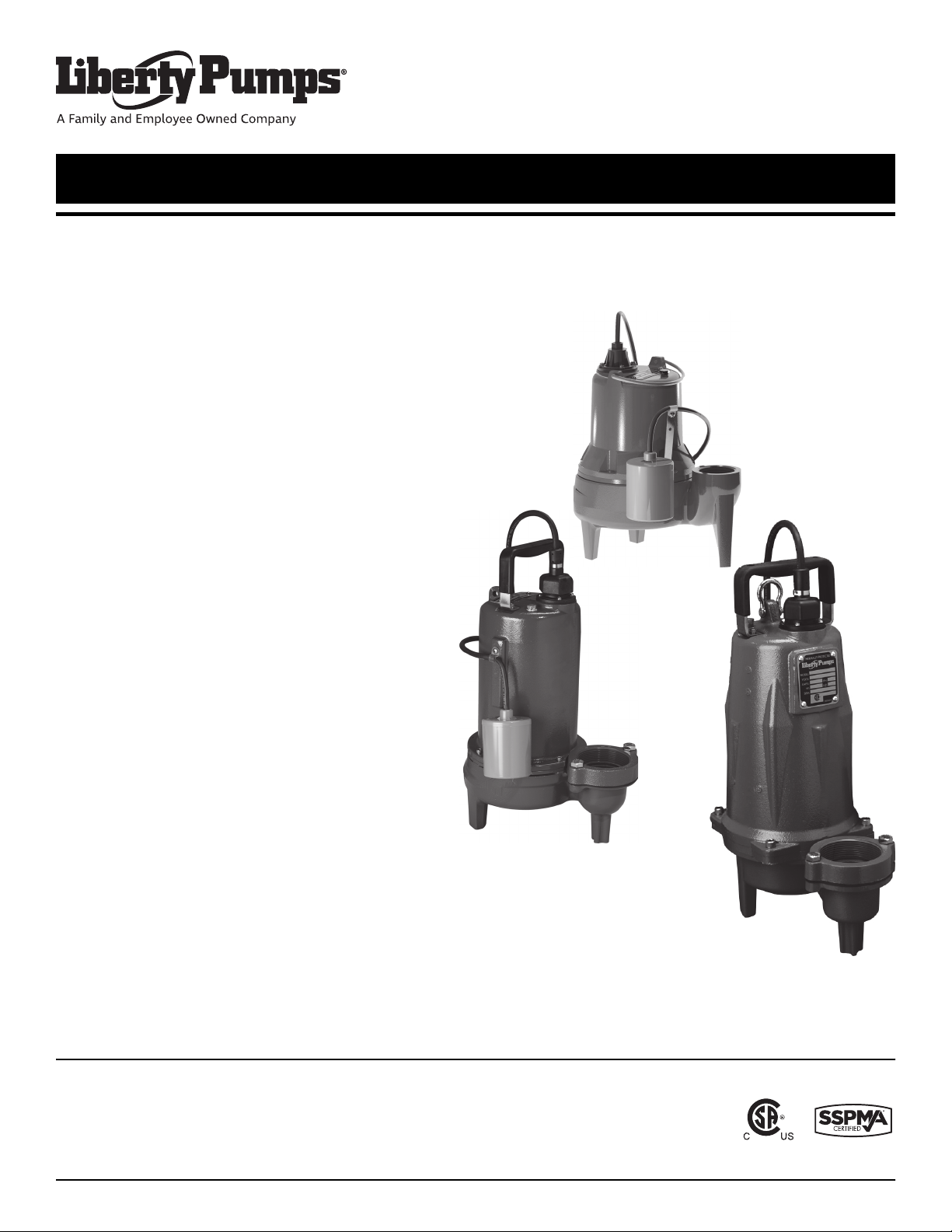
Submersible Sewage Pumps
LE and LEH-Series
Models
LE40-Series 4/10 hp
LE50-Series 1/2 hp
LE70-Series 3/4 hp
LE100-Series 1hp
7034000M
LEH100-Series 1hp
LEH150-Series 1-1/2 hp
LEH200-Series 2hp
7000 Apple Tree Avenue
Bergen, NY 14416
ph: 800-543-2550
fax: 585-494-1839
www.LibertyPumps.com
Copyright © Liberty Pumps, Inc. 2019 All rights reserved.
Page 2
Contents
Safety Precautions . . . . . . . . . . . . . . . . . . . . . . . . . . . . . . . . . . . . . . . . . . . . . . 3 | EN
General Information . . . . . . . . . . . . . . . . . . . . . . . . . . . . . . . . . . . . . . . . . . . . . .4 | EN
Operating Constraints . . . . . . . . . . . . . . . . . . . . . . . . . . . . . . . . . . . . . . . . . . . .4 | EN
Model Specifications . . . . . . . . . . . . . . . . . . . . . . . . . . . . . . . . . . . . . . . . . . . . 4 | EN
Inspection and Storage . . . . . . . . . . . . . . . . . . . . . . . . . . . . . . . . . . . . . . . . . . 4 | EN
Pump Design . . . . . . . . . . . . . . . . . . . . . . . . . . . . . . . . . . . . . . . . . . . . . . . . . . 5 | EN
Pump System Components . . . . . . . . . . . . . . . . . . . . . . . . . . . . . . . . . . . . . . . 5 | EN
Preparation . . . . . . . . . . . . . . . . . . . . . . . . . . . . . . . . . . . . . . . . . . . . . . . . . . . . 6 | EN
Installation . . . . . . . . . . . . . . . . . . . . . . . . . . . . . . . . . . . . . . . . . . . . . . . . . . . . 6 | EN
Operation . . . . . . . . . . . . . . . . . . . . . . . . . . . . . . . . . . . . . . . . . . . . . . . . . . . . . 9 | EN
Maintenance and Troubleshooting . . . . . . . . . . . . . . . . . . . . . . . . . . . . . . . . 9 | EN
Warranty . . . . . . . . . . . . . . . . . . . . . . . . . . . . . . . . . . . . . . . . . . . . . . . . . . . . . 12 | EN
Safety Guidelines
This safety alert symbol is used in the manual and on the pump to alert of potential risk for serious injury
or death.
This safety alert symbol identifies risk of electric shock. It is accompanied with an instruction intended to
minimize potential risk of electric shock.
This safety alert symbol identifies risk of fire. It is accompanied with an instruction intended to minimize
potential risk of fire.
This safety alert symbol identifies risk of serious injury or death. It is accompanied with an instruction
intended to minimize potential risk of injury or death.
Warns of hazards which, if not avoided, will result in serious injury or death.
Warns of hazards which, if not avoided, could result in serious injury or death.
Warns of hazards which, if not avoided, could result in minor or moderate injury.
Signals an important instruction related to the pump. Failure to follow these instructions could result in
pump failure or property damage.
Read every supplied manual before using pump system. Follow all the safety instructions in
manual(s) and on the pump. Failure to do so could result in serious injury or death.
Installer: manual must remain with owner or system operator/maintainer.
Keep this manual handy for future reference.
Record information from pump nameplate:
Pump Model #:
For replacement manual, visit LibertyPumps.com,
or contact Liberty Pumps at 1-800-543-2550.
Retain dated sales receipt for warranty.
2 | EN Copyright © Liberty Pumps, Inc. 2019 All rights reserved. 7034000M
Pump Serial #:
Manufacture Date:
Install Date:
Page 3
Safety Precautions
RISK OF ELECTRIC SHOCK
Accidental contact with electrically live parts, items, fluid, or
water can cause serious injury or death.
Always disconnect pump(s) from power source(s) before
handling or making any adjustments to either the pump(s),
the pump system, or the control panel.
All installation and maintenance of pumps, controls,
protection devices, and general wiring shall be done by
qualified personnel.
All electrical and safety practices shall be in accordance with
the National Electrical Code
Health Administration, or applicable local codes and
ordinances.
Do not remove cord and strain relief, and do not connect
conduit to pump.
Pump shall be properly grounded using its supplied
grounding conductor. Do not bypass grounding wires or
remove ground prong from attachment plugs. Failure to
properly ground the pump system can cause all metal
portions of the pump and its surroundings to become
energized.
Do not handle or unplug the pump with wet hands, when
standing on damp surface, or in water unless wearing
Personal Protective Equipment.
Always wear dielectric rubber boots and other applicable
Personal Protective Equipment (PPE) when water is on the
floor and an energized pump system must be serviced, as
submerged electrical connections can energize the water. Do
not enter the water if the water level is higher than the PPE
protection or if the PPE is not watertight.
Do not lift or carry a pump or a float assembly by its power
cord. This will damage the power cord, and could expose the
electrically live wires inside the power cord.
The electrical power supply shall be located within the length
limitations of the pump power cord, and for below grade
installations it shall be at least 4 ft (1.22 m) above floor level.
Do not use this product in applications where human contact
with the pumped fluid is common (such as swimming pools,
fountains, marine areas, etc.).
Protect the power and control cords from the environment.
Unprotected power and control (switch) cords can allow
water to wick through ends into pump or switch housings,
causing surroundings to become energized.
Single-phase 208/230V pumps shall only be operated
without the float switch by using the circuit breaker or panel
disconnect.
RISK OF FIRE
Do not use an extension cord to power the product.
Extension cords can overload both the product and extension
cord supply wires. Overloaded wires will get very hot and can
catch on fire.
®
, the Occupational Safety and
This product requires a separate, properly fused and
grounded branch circuit, sized for the voltage and amperage
requirements of the pump, as noted on the nameplate.
Overloaded branch circuit wires will get very hot and can
catch on fire. When used, electrical outlets shall be simplex of
the appropriate rating.
For cord replacement: power cord must be of the same
length and type as originally installed on the Liberty Pumps
product. Use of incorrect cord may lead to exceeding the
electrical rating of the cord and could result in death, serious
injury, or other significant failure.
Do not use this product with or near flammable or explosive
fluids such as gasoline, fuel oil, kerosene, etc. If rotating
elements inside pump strike any foreign object, sparks may
occur. Sparks could ignite flammable liquids.
Sewage and effluent systems produce and may contain
flammable and explosive gases. Prevent introduction of
foreign objects into basin as sparks could ignite these gases.
Exercise caution using tools and do not use electronic devices
or have live, exposed electrical circuits in or around basins,
open covers and vents.
Manual pumps that have been factory constructed with a
power cord with no male attachment plug must use an
approved motor control panel. Do not wire a switch in series
with the pump power cord as this can overload the wires.
Overloaded wires get very hot and can catch on fire.
These pumps are not to be installed in locations classified as
hazardous in accordance with the National Electric Code
®
,
ANSI/NFPA 70.
RISK OF SERIOUS INJURY OR DEATH
Do not modify the pump/pump system in any way.
Modifications may affect seals, change the electrical loading
of the pump, or damage the pump and its components.
All pump/pump system installations shall be in compliance
with all applicable Federal, State, and Local codes and
ordinances.
Do not allow children to play with the pump system.
Do not allow any person who is unqualified to have contact
with this pump system. Any person who is unaware of the
dangers of this pump system, or has not read this manual,
can easily be injured by the pump system.
In 208/230V installations, one side of the line going to the
pump is always “hot”, whether the float switch is on or off. To
avoid hazards, install a double pole disconnect near the
pump installation.
Vent basin in accordance with local code. Proper venting of
sewer and effluent gases alleviates poisonous gas buildup
and reduces the risk of explosion and fire from these
flammable gases.
Wear adequate Personal Protective Equipment when working
on pumps or piping that have been exposed to wastewater.
Sump and sewage pumps often handle materials that can
transmit illness or disease upon contact with skin and other
tissues.
Do not enter a pump basin after it has been used. Sewage
and effluent can emit several gases that are poisonous.
7034000M Copyright © Liberty Pumps, Inc. 2019 All rights reserved. 3 | EN
Page 4
Do not remove any tags or labels from the pump or its cord.
Keep clear of suction and discharge openings. To prevent
injury, never insert fingers into pump while it is connected to
a power source.
Do not use this product with flammable, explosive, or
corrosive fluids. Do not use in a flammable and/or explosive
atmosphere as serious injury or death could result.
This product contains chemicals known to the State of
California to cause cancer and birth defects or other
reproductive harm. www.p65warnings.ca.gov.
Verify 3-phase pumps for proper rotation prior to installing
pump(s) in basin. To change rotation, reverse any two of the
three power leads to the pump (not the ground). Code the
wires for reconnection after installation.
Do not dispose of materials such as paint thinner or other
chemicals down drains. Doing so could chemically attack and
damage pump system components and cause product
malfunction or failure.
Do not use pumps with fluid over 140°F (60°C). Operating the
pump in fluid above this temperature can overheat the pump,
resulting in pump failure.
Do not use pump system with mud, sand, cement,
hydrocarbons, grease, or chemicals. Pump and system
components can be damaged from these items causing
product malfunction or failure. Additionally, flooding can
occur if these items jam the impeller or piping.
Do not introduce any consumer item that is not toilet paper
into a non-grinder (dewatering/effluent or sewage) pump/
pump system. This includes, but is not limited to the
following: feminine products, wipes, towels, towelettes,
dental floss, swabs, pads, etc. Items such as these put the
pump under undo strain and can result in pump/pump
system failure. Additionally, it creates conditions for
discharge line blockage.
Do not run dry.
The Uniform Plumbing Code® states that sewage systems
shall have an audio and visual alarm that signals a
malfunction of the system, to reduce the potential for
property damage.
Do not exert heavy pressure or run heavy equipment on the
backfill material as this could cause the tank to collapse.
Do not position the pump float directly under the inlet from
drain tile or in the direct path of any incoming water.
Keep pump upright.
Do not allow pump to freeze.
At no time shall the pump be stored within an incomplete wet
basin. The pump shall not be placed into the basin until it can
be fully operational.
General Information
Before installation, read these instructions carefully.
Each pump is individually factory tested to ensure
proper performance. Closely following these
instructions will eliminate potential operating
problems, assuring years of trouble-free service.
These pumps are to be used for handling septic
tank effluent, sewage, and drain (storm) water.
Provide pump serial number in all correspondence.
Pumps are certified to CSA® and UL® standards.
Pumps must be serviced at a qualified repair facility
approved by Liberty Pumps. No repair work should
be carried out during the warranty period without
prior factory approval. Any unauthorized field
repairs void warranty. Contact Liberty Pumps at
1-800-543-2550 to locate the closest authorized
service center.
Operating Constraints
It is extremely important to verify that the pump
has been sized correctly for the intended
installation. The operating point of the pump must
lie within the acceptable range as outlined by the
applicable Liberty Pumps performance chart.
Operating the pump outside of the recommended
range can invalidate the CSA Certification of the
pump and can also cause damage and premature
failure. Operating outside of the recommended
range can cause the pump to exceed its rated
nameplate amp draw, which will void the pump
certification. It can also cause motor overheating,
cavitation, excessive vibration, clogging, and poor
energy efficiency.
Model Specifications
For complete listing of pump models and their specifications, refer
to http://www.LibertyPumps.com/About/Engineering-Specs.
Pump nameplate provides a record of specific pump information.
Inspection and Storage
Initial Inspection
Inspect pump immediately for damage that may have occurred in
shipment.
1. Visually check the pump and any spare parts for damage.
2. Check for damaged electrical wires, especially where they exit
the motor housing.
Contact Liberty Pumps customer service to report any damage or
shortage of parts.
4 | EN Copyright © Liberty Pumps, Inc. 2019 All rights reserved. 7034000M
Page 5

Storage Before Use
RISK OF ELECTRIC SHOCK
Protect the power and control cords from the environment.
Unprotected power and control (switch) cords can allow
water to wick through ends into pump or switch housings,
causing surroundings to become energized.
IMPORTANT: When connecting a new pump to an existing
control panel, verify the panel is correctly sized and equipped for
the pump.
Control panels designed for use with specific pumps available
from Liberty Pumps can be found at http://
www.LibertyPumps.com/Portals/0/Files/panel_selection_guide.pdf
or contact Liberty Pumps.
Float Switches
At no time shall the pump be stored within an incomplete wet
basin. The pump shall not be placed into the basin until it can
be fully operational.
Do not allow the pump to freeze.
Pumps are shipped from the factory ready for installation and use.
Hold the pump in storage if the pump station is not complete.
If storage is necessary, the pump should remain in its shipping
container. It should be stored in a warehouse or storage shed that
has a clean, dry temperature-stable environment where the pump
and its container are covered to protect it from water, dirt,
vibration, etc. The cord ends must be protected against moisture.
Uninstalled pumps that are idle for greater than three months
should have impellers manually rotated once a month to lubricate
the seals.
Installed pumps that are idle for greater than one month should
have impellers manually operated through the breaker panel once
a month to lubricate the seals. For automatic models, turn off the
breaker, unplug the piggyback switch, and plug the pump directly
into the wall socket. Turn the breaker on for 30 seconds, then turn
the breaker off. Plug the piggyback switch back in. Refer to
Figure 1 on page 8.
Pump Design
Some LE and LEH-Series pumps come equipped with an air bleed
hole to help prevent airlock. A small spray of water from this hole
is normal while pump is running.
Pump System Components
Control Panel
Manual models (“M” suffix) and 3-phase models require a
separate, approved pump control device or panel for automatic
operation. Operation will be according to the control panel
selected. Refer to separate manufacturer’s instructions supplied
with the unit. Verify the electrical specifications for the control
panel properly match those of the pump. 3-phase models require
overload elements selected or adjusted in accordance with the
control or panel instructions.
Mounting, installation, and wiring connections are specific to the
control panel used. Refer to the manufacturer’s instructions
supplied with the unit.
RISK OF ELECTRIC SHOCK
Single-phase 208/230V pumps shall only be operated
without the float switch by using the circuit breaker or panel
disconnect.
Automatic Models
All LE-Series automatic models (“A” suffix) come factoryequipped with a float switch mounted to the pump. These models
come with two cords—one to the float switch and the other to the
pump motor. The switch cord has a series (piggyback) plug
enabling the pump motor cord to be plugged into the back of it.
The purpose of this design is to allow temporary manual
operation of the pump.
For manual operation, or in the event of float switch failure, the
pump cord can be separated and plugged into the electrical
outlet, directly bypassing the switch. Refer to Piggyback Switch
Operation on page 8.
If using a differential other than the factory setting, verify that
when the pump turns off, the minimum fluid level left in the basin
is per Table 1 so the impeller remains submerged. Other pumping
differentials may be obtained by tethering the float switch cord to
the discharge pipe.
Note: With wide-angle floats, a minimum cord length of 3-1/2”
from the tether point to the top surface of the float is required for
proper float switch operation.
Note: If the factory-mounted float is removed from the pump for
relocation to the discharge pipe, replace and tighten all pump
hardware.
Switchless (Manual) Models
Manual pumps with no float switch are intended to be run using
an approved liquid level control or approved motor control with
correct rating that matches motor input in full load amperes.
Regardless of the control type, verify that when the pump shuts
off, the minimum fluid level left in the basin is per Table 1 so the
impeller remains submerged.
IMPORTANT: Manual pumps factory constructed with a power
cord with no male attachment plug must use an approved motor
control panel. Do not wire a switch in series with the pump power
cord.
Automatic operation with optional control devices: if the
pump(s) are to be operated by either a simplex or duplex control
panel, or other optional control device, follow the manufacturer’s
instructions provided with the control panel for power
connections.
7034000M Copyright © Liberty Pumps, Inc. 2019 All rights reserved. 5 | EN
Page 6

Float Switch Settings
Table 1 includes factory set float levels for automatic models. The
turn OFF level must be maintained as it is the minimum water
depth to ensure proper cooling. Manual pumps have user set turn
ON levels.
Table 1. Factory Set Float Switch Settings
Model Series Turn OFF Level Turn ON Level
LE40 7” 15”
LE41AV 5.5” 11”
LE50 6” 14”
LE51AV 5.5” 11”
LE50 6” 14”
LE70 8.4” 16.4”
LE100 8.4” 16.4”
LEH150 9” 16.5”
LEH200 16.5”
user set
Preparation
RISK OF ELECTRIC SHOCK
Always disconnect pump(s) from power source(s) before
handling or making any adjustments to either the pump(s),
the pump system, or the control panel.
The basin required for both effluent and sewage applications
must be sealed and vented to meet health and plumbing code
requirements. Proper basin size and materials for specific
applications vary depending on the type of system and local
codes. Check local codes prior to purchasing and installing the
basin.
The diameter should be a minimum of 18” and the depth a
minimum of 24”. A larger basin may be required depending on
local codes and the number of fixture units entering the system.
Check with the local authorities or contact Liberty Pumps if unsure
of the proper basin size. Installation should be at a sufficient
depth to ensure that all plumbing is below the frost line. If this is
not feasible, size the basin and/or adjust pump differential to
accommodate the additional backflow volume.
Prepare Existing Sump [Basin]
Prepare New Sump [Basin]
Excavation
RISK OF SERIOUS INJURY OR DEATH
Locate all overhead and underground utilities before
excavating.
Excavate the hole as small as possible, with a minimum
recommended 8" diametrical clearance around the tank. Never
place the basin directly in contact with rocks or other sharp
objects. Place only fine, 1/8” to 3/4” pea gravel or 1/8” to 1/2”
washed, crushed stone as bedding between the basin and the
hole walls. Do not use sand or native soil as backfill. Properly
compact underneath the basin to provide a solid, level base that
can support the weight of the filled basin.
Inlet Connection & Initial Backfill
Use only fine, 1/8” to 3/4” pea gravel or 1/8” to 1/2” washed,
crushed stone around the bottom of the basin to hold it in place.
Do not use sand or native soil as backfill.
Make the inlet connection as required per basin.
Liberty Pumps P370 and P380-Series basins have a 4" inlet
molded to the side of the tank. This inlet is sized to accept a 4"
no-hub type coupling. Connect the gravity drainage line from the
fixtures to this hub.
Other Liberty Pumps basins provide a 4" caulking hub or pipe
grommet inlet. Hubs utilize caulking material or rubber donuts;
grommets are a simple slip-fit. Connect the gravity drainage line
from the fixtures to this opening. Other inlet sizes are available,
consult factory.
Final Backfill
Keep large rocks, clods, and foreign objects out of the backfill
material. Only fine, 1/4” to 3/4” pea gravel, or 1/8” to 1/2” washed,
crushed stone is recommended. Do not use sand or native soil as
backfill. Mound the backfill slightly and allow for natural settling.
Provide access to the basin cover for maintenance and service.
Compaction of backfill materials must be adequate to ensure the
support of the tank, and to prevent movement or settlement.
Do not exert heavy pressure or run heavy equipment on the
backfill material as this could cause the tank to collapse.
Installation
If replacing a previously installed pump, prepare the basin by
removing the old pump and cleaning any debris from the basin.
Inspect all remaining equipment in the basin including piping,
valves, and electrical junction boxes (if present) and repair or
replace as appropriate.
6 | EN Copyright © Liberty Pumps, Inc. 2019 All rights reserved. 7034000M
All installation and maintenance of pumps, controls,
protection devices, and general wiring shall be done by
qualified personnel.
All electrical and safety practices shall be in accordance with
the National Electrical Code
Health Administration, or applicable local codes and
ordinances.
RISK OF ELECTRIC SHOCK
®
, the Occupational Safety and
Page 7

SYSTEM
VENT
DISCHARGE
Ground Level
Optional Above
Ground Vent
SEWAGE LINE
INDOOR APPLICATION
OUTDOOR APPLICATION
Electrical Connections
Discharge
With main power disconnected, complete pump and control
wiring connections per manufacturer’s wiring diagrams included
with the control panel as applicable. Once connections are made,
all wires should be checked for unintentional grounds.
3-Phase Pump Rotation Verification
Check 3-phase pumps for proper rotation prior to installing
pump(s) in basin. To change rotation, reverse any two of the
three power leads to the pump (not the ground). Code the
wires for reconnection after installation.
3-phase power uses three separate
BOTTOM VIEW
alternating currents that peak at different
integrals. With pumps that are powered by
three phase electric, the phase sequence of
the motor must match the phase sequence
of the power source. When the phase
sequences match, the pump operates
properly.
ROTATION
However, when the phases are out of order, the pump runs
backward (i.e., the impeller rotates in the wrong direction). This
causes an extreme loss of performance and could raise the current
draw, which could result in tripping an overload or circuit breaker.
To ensure that the power to the pump is installed correctly, always
verify proper rotation before lowering it into the basin. If the
pump is rotating in the wrong direction, turn off the power and
reverse any two leads to the pump (not ground). This reverses the
phase sequence and corrects the pump rotation. For 3-phase
pumps, rotation must be counterclockwise when looking from the
bottom of the pump. Label the wires for reconnection after
installation.
A check valve is required to prevent the backflow of liquid after
each pumping cycle. A gate valve should follow the check valve to
allow periodic cleaning of the check valve or removal of the pump.
The remainder of the discharge line should be as short as possible
with a minimum number of turns to minimize friction head loss.
Do not reduce the discharge to below that which is provided
on the pump. Larger pipe sizes may be required to eliminate
friction head loss over long runs. Contact Liberty Pumps or other
qualified person if questions arise regarding proper pipe size and
flow rates.
Vent
The basin must be completely sealed and properly vented per
local health and plumbing code requirements. The system is
designed to be vented through the inlet to an existing building
vent stack. In order to accomplish this, there must be no traps
between the system inlet and the nearest building vent stack
connection. If this is not possible or desirable per the application,
a vent flange or grommet can be installed in a hole cut into the
cover.
Guide Rail System
If guide rails are used, refer to the separate instructions supplied
with the unit for proper installation and operation, making sure all
gaskets and components are present. Liberty Pumps Guide Rail
System features a self-aligning mounting bracket. Contact Liberty
Pumps for available models, such as GR22 and GR30.
If guide rails are not used, complete all pump-mounted plumbing
at this time, being sure all gaskets and components are present.
Pump
Record information from pump nameplate onto inside cover of
these instructions. Complete a visual inspection before lowering
into basin.
7034000M Copyright © Liberty Pumps, Inc. 2019 All rights reserved. 7 | EN
Page 8

Temporary Manual
YES!NO!
Install cable
clamp to wall
for strain relief
Temporary Manual
YES!NO!
Ground
Black
Junction Box
Power
Supply
White
Float
Switch
Pump
Green
Black
White
Green
Black
White
Vent
Discharge
Union Gate ValveCheck Valve
On 370-Series tanks,
use no-hub type
coupling
4” inlet pipe
On 700-Series
tanks, caulking
hub used
4” inlet pipe
Piggyback Switch Operation
Applications
RISK OF ELECTRIC SHOCK
Single-phase 208/230V pumps shall only be operated
without the float switch by using the circuit breaker or panel
A securable basin cover is required for safety and to prevent
foreign objects from entering the basin.
Simplex (One Pump) Systems
disconnect.
IMPORTANT: Verify breaker is turned off before plugging in the
switch.
Plug the piggyback switch into the receptacle. The receptacle
must be wired to an appropriately sized breaker. Plug the pump
into the piggyback receptacle. Install the cable clamp (if supplied)
for strain relief.
Operation
Operation
Figure 3. Typical Simplex System Installation (variations may apply)
Figure 1. Piggyback Switch Operation
1. Place pump in basin making certain the mounting interface
Automatic Pump Direct Wiring
(i.e., guide rail, torque stop) is engaged correctly. Float switch
must have adequate clearance to side wall of basin and free,
unobstructed movement throughout its complete travel and
RISK OF SERIOUS INJURY OR DEATH
must not contact the pump, piping, or other objects.
2. If an optional control device or float is used, follow the
In 208/230V installations, one side of the line going to the
pump is always “hot”, whether the float switch is on or off. To
avoid hazards, install a double pole disconnect near the
pump installation.
If a 1-phase pump (excluding model LEH202) will be wired directly
into a control device or junction box, and it is necessary to remove
the plug, a certified electrician shall complete the wiring in
accordance with the National Electric Code and applicable local
codes. See Figure 2 for direct wire installation of 1-phase,
automatic pumps.
separate manufacturer’s instructions for mounting. Minimum
pump turn OFF level must not be set below Table 1 values.
3. Connect the discharge pipe to the pump's threaded
discharge. Do not reduce the discharge to below that which
is provided on the pump. Sewage pumps should not be
smaller than 2". Larger pipe sizes may be required in some
applications to reduce friction head loss over long runs.
Contact Liberty Pumps or other qualified person if there are
questions regarding proper pipe size and flow rates.
4. Mount and seal the basin cover.
5. Install the remaining discharge line.
6. Install a union just above the cover to facilitate pump removal
when necessary.
7. Install a check valve after the union to prevent backflow after
each pumping cycle.
8. Install a gate valve after the check valve to allow periodic
cleaning of the check valve and removal of the pump.
9. The remainder of the discharge line should be as short as
Figure 2. Direct Wiring of 115 V or 208/230 V, 1-Phase, Automatic
8 | EN Copyright © Liberty Pumps, Inc. 2019 All rights reserved. 7034000M
possible with a minimum number of turns to minimize friction
head loss. Larger pipe sizes may be required to eliminate
friction head loss over long runs.
10. Vent basin in accordance with applicable plumbing codes.
Page 9

Duplex (Two Pump) Systems
Pump #1
Pump #2
Control Floats
Discharge
Vent
Unions
Inlet
Gate Valve Gate Valve
Check Valves
Leads to
Control
Panel
Te e
Figure 4. Typical Duplex System Installation (variations may apply)
8. The remainder of the discharge line should be as short as
possible with a minimum number of turns to minimize friction
head loss. Larger pipe sizes may be required to eliminate
friction head loss over long runs.
9. Vent basin in accordance with applicable plumbing codes.
Operation
Starting System
1. Verify all plumbing components are installed correctly and
functional. Verify all valves are open and ready for pump use.
2. Double check all wire connections. Re-tighten all factory and
field connections.
3. Ensure pump has no obstructions.
4. With all electrical and mechanical connections complete and
secure, turn on power to pump and control panel, if
applicable.
5. Verify operation of the pump, floats, and alarm circuits.
6. Run several cycles of water through the system to verify
correct control operation for the installation.
Be certain to complete adequate testing, especially on systems
with multiple pumps or custom control configurations.
1. Place both pumps in basin, making certain the mounting
interface (i.e., guide rail, torque stop) is engaged correctly.
The duplex control used will include 3 or 4 floats that will
either be tethered to one of the discharge pipes or to an
independent rod or bracket. Follow the duplex control
manufacturer’s instructions provided with the device. Each
float switch must have adequate clearance to side wall of
basin and free, unobstructed movement throughout its
complete travel and must not contact the pump, piping, or
other objects. Minimum pump turn OFF level must not be set
below Table 1 values.
2. Connect an individual discharge pipe to each pump. Do not
reduce the discharge to below that which is provided on the
pump. Sewage pumps should not be smaller than 2". Larger
pipe sizes may be required in some applications to reduce
friction head loss over long runs. Contact Liberty Pumps or
other qualified person if there are questions regarding proper
pipe size and flow rates.
3. A check valve on each discharge line, prior to tying into one
common line, is necessary to prevent the recycling of fluid
from one pump to the other. Depending on the basin height,
the check valves may either be inside or outside the basin. To
install inside basin, install check valve on each discharge pipe
now. To install outside basin, install in Step 6.
4. Mount and seal the basin cover.
5. Install unions or flexible connectors just above the cover on
each discharge to facilitate pump removal when necessary.
6. Install check valves on each discharge after the union and
prior to the gate valve to prevent backflow.
7. Install a gate valve after the check valve to allow for periodic
cleaning of the check valve and removal of pumps.
Maintenance and Troubleshooting
RISK OF ELECTRIC SHOCK
Accidental contact with electrically live parts, items, fluid, or
water can cause serious injury or death.
Always disconnect pump(s) from power source(s) before
handling or making any adjustments to either the pump(s),
the pump system, or the control panel.
RISK OF SERIOUS INJURY OR DEATH
Wear adequate Personal Protective Equipment when working
on pumps or piping that have been exposed to wastewater.
Sump and sewage pumps often handle materials that can
transmit illness or disease upon contact with skin and other
tissues.
Do not enter a pump basin after it has been used. Sewage
and effluent can emit several gases that are poisonous.
Verify correct 3-phase pump rotation before retuning to
service.
7034000M Copyright © Liberty Pumps, Inc. 2019 All rights reserved. 9 | EN
Page 10

Maintenance
Troubleshooting
Check pump frequently for debris and/or build up that may
interfere with pump or float switch operation. As the motor is
oil-filled, no lubrication or other maintenance is required.
In the event the pump becomes clogged, the inlet screen can be
removed to gain access to the pump impeller. Once the
obstruction is removed, the anti-airlock hole should be cleaned.
Table 2. Troubleshooting Matrix
Problem Possible Cause Corrective Action
Damaged power or control cord. Replace as needed.
Control panel selector switch in OFF position. Set selector switch to Hand or Auto position.
Blown control circuit transformer fuse. Replace fuse.
Tripped circuit breaker, tripped GFCI, blown fuse,
or other interruption of power.
Improper voltage.
Pump does not start.
Float switch unable to move to PUMP ON
position due to interference in basin or other
obstruction.
No repair work shall be carried out during the warranty period
without prior factory approval. To do so may void the warranty.
Liberty Pumps, Inc. assumes no responsibility for damage or injury
due to disassembly in the field. Disassembly, other than an
authorized repair facility approved by Liberty Pumps or its
authorized service centers, automatically voids warranty.
Reset tripped circuit breaker, reset GFCI, replace blown
fuse with properly sized fuse, check that the unit is
securely plugged in, investigate power interruption.
Have an electrician check all wiring for proper
connections and adequate voltage and capacity.
Position pump or float switch so that it has adequate
clearance for free movement.
Pump runs, but does
not turn off.
Pump runs or hums, but
does not pump.
Insufficient liquid level.
Defective float switch. Replace float switch.
Obstructed impeller or volute. Remove obstruction.
Loose wiring connections. Check and tighten all connections.
Pump is airlocked.
Control panel selector switch in Hand position. Set selector switch to Auto position.
Float switch unable to move to PUMP OFF
position due to interference with the side of
basin or other obstruction.
Control panel failure. Check control panel.
Defective float switch. Replace float switch.
Discharge line blocked or restricted.
Check valve is stuck closed or installed backward.
Gate or ball valve is closed. Open gate or ball valve.
Total head (lift height) is beyond pump's
capability.
Verify liquid level is allowed to rise enough to activate
float switch(es).
Turn pump off and let set for several minutes, then restart.
Position pump or float switch(es) so that it has adequate
clearance for free movement.
Check discharge line for foreign material, including ice if
discharge line passes through or into cold areas.
Remove check valve(s) and examine for freedom of
operation and proper installation.
Route piping to a lower level. If not possible, a larger
pump may be required. Consult Liberty Pumps.
Obstructed impeller or volute. Remove obstruction.
Pump is airlocked.
10 | EN Copyright © Liberty Pumps, Inc. 2019 All rights reserved. 7034000M
Turn pump off and let set for several minutes, then restart.
Add baffle to reduce trapped air bubbles.
Page 11

Table 2. Troubleshooting Matrix (continued)
Problem Possible Cause Corrective Action
Pump cycles too
frequently.
Pump runs periodically
when fixtures are not in
use.
Pump does not deliver
proper capacity.
Pump operates noisily.
Improper float switch setting. Adjust float switch setting.
Check valve not installed, stuck open, or leaking.
Check valve not installed, stuck open, or leaking.
Install check valve(s); remove check valve and examine
for freedom of operation and proper installation.
Install check valve(s); remove check valve and examine
for freedom of operation and proper installation.
Fixtures are leaking. Repair fixtures as required to eliminate leakage.
Discharge valve(s) partially closed or clogged.
Check valve partially clogged.
Check the discharge line for foreign material, including
ice if the discharge line passes through or into cold areas.
Raise liquid level up and down to clear; remove check
valve to remove obstruction.
Incorrect 3-phase motor rotation. Correct 3-phase pump rotation direction.
Total head (lift height) is beyond pump's
capability.
Route discharge piping to a lower level. If not possible, a
larger pump may be required. Consult Liberty Pumps.
Low liquid level. Check liquid level.
Obstruction in pump or piping. Remove obstruction.
Piping attachments to building are too rigid.
Replace a portion of the discharge line with rubber hose
or connector.
Incorrect 3-phase motor rotation. Correct 3-phase pump rotation direction.
Foreign objects in the impeller cavity. Clean the impeller cavity.
Repeated tripping.
Broken impeller.
Consult Liberty Pumps for information regarding impeller
replacement.
Circuit protection underrated. Check rating and replace with proper size.
Other appliance on same circuit. Pump requires separate circuit.
Pump is connected to an extension cord or
wiring is inadequate or compromised.
Improper voltage.
Have an electrician check for proper wiring.
Have an electrician check all wiring for proper
connections and adequate voltage and capacity.
Obstruction in pump. Remove obstruction.
Incorrect 3-phase motor rotation. Correct 3-phase pump rotation direction.
Foreign matter buildup. Clean motor housing.
7034000M Copyright © Liberty Pumps, Inc. 2019 All rights reserved. 11 | EN
Page 12

Warranty
7000 Apple Tree Avenue
Bergen, NY 14416
ph: 800-543-2550
fax: 585-494-1839
www.LibertyPumps.com
Liberty Pumps Wholesale Products Limited Warranty
Liberty Pumps, Inc. warrants that Liberty Pumps wholesale products are free from all factory defects in material and workmanship for a
period of three (3) years from the date of purchase (excluding batteries). The date of purchase shall be determined by a dated sales
receipt noting the model and serial number of the pump. The dated sales receipt must accompany the returned pump if the date of
return is more than three years from the date of manufacture noted on the pump nameplate.
The manufacturer's sole obligation under this Warranty shall be limited to the repair or replacement of any parts found by the
manufacturer to be defective, provided the part or assembly is returned freight prepaid to the manufacturer or its authorized service
center, and provided that none of the following warranty-voiding characteristics are evident:
The manufacturer shall not be liable under this Warranty if the product has not been properly installed, operated, or maintained per
manufacturer instructions; if it has been disassembled, modified, abused, or tampered with; if the electrical cord has been cut, damaged,
or spliced; if the pump discharge has been reduced in size; if the pump has been used in water temperatures above the advertised rating;
if the pump has been used in water containing sand, lime, cement, gravel, or other abrasives; if the product has been used to pump
chemicals, grease, or hydrocarbons; if a non-submersible motor has been subjected to moisture; or if the label bearing the model and
serial number has been removed.
Liberty Pumps, Inc. shall not be liable for any loss, damage, or expenses resulting from installation or use of its products, or for indirect,
incidental, and consequential damages, including costs of removal, reinstallation or transportation.
There is no other express warranty. All implied warranties, including those of merchantability and fitness for a particular purpose, are
limited to three years from the date of purchase. This Warranty contains the exclusive remedy of the purchaser, and, where
permitted, liability for consequential or incidental damages under any and all warranties are excluded.
12 | EN Copyright © Liberty Pumps, Inc. 2019 All rights reserved. 7034000M
 Loading...