

Liberty Grandview FC-M, FC-MF, FC-MI Instruction Manual
In- line sw itch mo tor ized sc ree n &
Intell ige nt control motoriz ed sc reen
Instruction Manual Of Fancy
Series Motorized Screen
Model:
FC- M
FC- MI
FC- MF
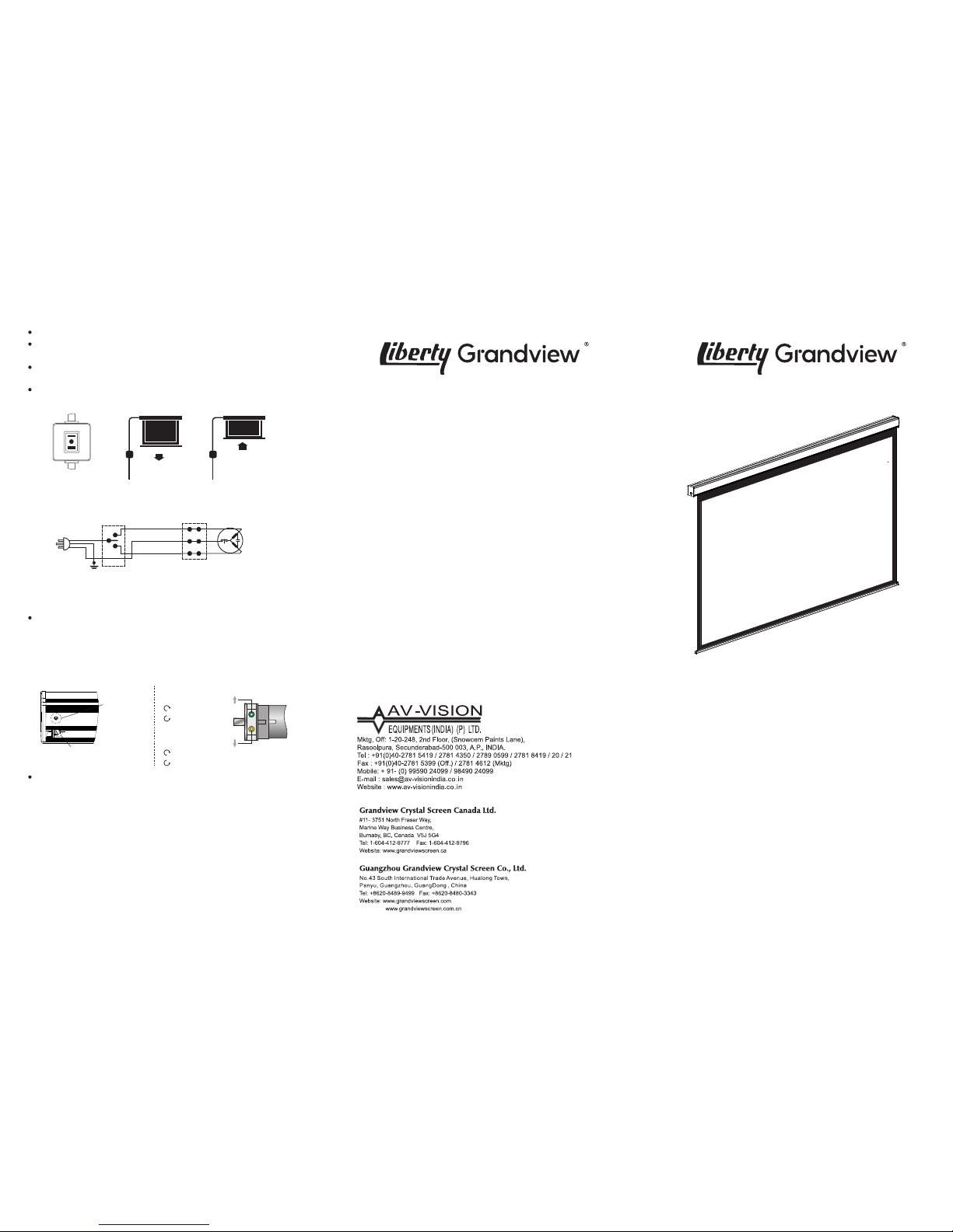
Mot orize d scree n (M) man ual control m ethod :
Mot orize d scree n (M) cir cuit di agram:
Scr een man ual con trol in- line sw itch (F igure 1)
Ext end scr een (Fig ure 2): Pre ss “= ” swit ch, scree n will
aut omati cally l ower dow n to desi re limi t posit ion.
Ret ract sc reen (Fi gure 3) : Pre ss “-” swi tch, scre en will
aut oatic ally re tract t o setti ng limi t posit ion.
Sto p scree n: Pre ss midd le “o” switc h, screen w ill sto p
imm ediat ely.
Figure 1
Extend screen
Figure 2 Figure 3
Retract screen
AC 22 0~230 V
50~ 60Hz, 40W
Yellow G reen
M
K1
Scre en retr act
(Bla ck wire )
Scre en exte nd
(Gre y wire)
Commo n groun d
(Blue w ire)
Screen r etract heigh t (Up limit) and e xtend height ( down limit)
adjustment:
If ha ve to adju st heig ht limi t for ins talla tion env ironm ent
rea sons, you c an adju st the li mit set ting by us ing a pro vided
adj ustme nt bar in sert in to the ad justm ent hol e which o n the
lef t down ar ea of mot or. As be low fig ure:
Note : Whe n scree n retra ct heig ht over t he sett ing lim it, fabri c will
auto matic ally lo wer dow n. For this ca se, pleas e press s top swi tch (By m anual
or RF co ntrol ), micro ad just on g reen kn ob in clo ckwi se dire ction i s fine.
Scre en up lim it
sett ing pos ition
Scre en up
and do wn
limi t setti ng
area
Gree n hole
Retra ct limi t (up lim it)
Clock wise di recti on:
retra ct less
Yellow h ole
Exten d heigh t (down l imit)
Clock wise di recti on:
exten d less
Anti- clock wise di recti on:
exten d more
electr ic moto r
Trou ble sho oting : Prod uct ha s the over r etrac t prote ction
sys tem. When sc reen ove r retra ct, unde r bar wil l
aut omati cally l ower whi ch mean s have to re set the u p limit .
Ple ase che ck moto r limit s ettin g metho d for refe rence.
Not e:
Ple ase ope rate car efull y, in ca se of scr een ove r retrac t caus ing mot or
or sc reen da mage.W hile ex tendi ng more f abric , ple ase add b lack
boa rder wi thin 10 CM or it wi ll caus e fabri c break a nd fall .
Scr een ele ctric d ata: Volta ge AC220 -230V /50-6 0Hz, cur rent 0.5 A,
powe r 100W.
RF re mote (F) : Volt age 3V, use CR 2450* 1 batte ry, ratio fr equen cy:
433 Hz. maxim um cont rol dis tance 15 m.
IR re mote (R) : Volt age 12V, use 2 7A*1 ba ttery, max imum co ntrol
dis tance 8 m.
For long lasti ng enjoyi ng the best v iewin g expe rience of
Gra ndvie w scr een, pleas e ret ract scr een i nto c asing
whi le not use. Befo re retr actin g into ca sing, ple ase check
scr een f ront and back side to ensure surfa ce ha s no
obv ious du st, insec ts or any thing d irty. If th ere’s anythin g
dir ty, pleas e use sof t cloth c lean it c arefu lly fir st.
Maintain Screen:
Anti- clock wise di recti on:
retra ct more
Plea se use warm water mixe d with mild de tergent sl ightly
clea n the dirt on scree n casing or sur face (Please cle an
gent le instead of roughly). The n use a clean soft cloth or
towel dry it, please be noted it can’t be natural air drying.
Cleaning Screen:
Plea se don’t use any solvent or chemic al liquid or any
frictio nal clean er, or these cleaner will cause permanent
damage on fabric.
LED
Dear Customers:
Tha nk you for p urcha sing a Gr andvi ew proj ectio n scree n.
Bef ore use, p lease r ead ins truct ion car efull y. After i nstal latio n,
ple ase sto re inst ructi on for fu ture ref erence .
Φ5x40 t appin g screw X 8 p cs
Expa nsion f ixtur e X 8 pcs
Preparation for installation
Acce ssories pa ck:
Brac ket X 2 pcs
Moto r limit
sett ing too l X 1 pcs
Floa ting
Brac ket X 2 pcs
Wall/Ceiling installation method
Ins tall br acket o nto wal l/cei ling th at
can b ear suc h weigh t, and kee p
scr een two s ides on a s ame leve l.
(Di stanc e from ca sing en d with
10c m), as be low fig ure:
M
ark a c
l
e
a
na
bl
e l
eve
l l
i
ne
Loo sen the d own scre w until t he scre w can cove r the cas ing,
as fi gure:
Hol d the cas ing two e nds fla tly ont o the brac ket the n push
int o the bra cket, wh en the lo ckin g tooth f ixed, yo u will he ar a
loc king so und tha t means s creen a lread y fixed on to brac ket
saf ely. Lock s crew an d fix scr een. As f igure:
Up loc king
toot h
Down
lock ing
toot h
Rut, f or fix
purp ose
The bu tton
for un insta ll
scre en
Not e: When ta king of f scree n, loos en the bo ttom sc rew fir st
and p ush the t op loos en butt on, the n you can ea sily ta ke the
scr een off, a s above fi gure:
Ceiling hanging method:
Use c eilin g hangin g brack et lock i nto the r ut and it h as a
han ging ho le ther e, as figu re:
Take re feren ce same as w all/c eilin g insta llati on, mea sure
ins talla tion di stanc e and mar k posit ion, th e fix scr een cas ing
ste ady wit h brack et.
Acco rding t o site in stall ation h eight , insta ll hook o nto ceil ing,
the n hang th e scree n throug h brack et hole . As figu re:
Warn ing:
Bef ore oper ate scr een, ma ke sure t he stic ker on ca sing an d
und er bar is r emoved .
Imp orta nce:
Fabric control instruction
Int ellig ent mot orize d screen h as 4
con trol opt ions:
A. Ma nual co ntrol ( cycle c ontrol b utton )
B. IR co ntrol o r RF cont rol
C. Dr y conta ct cont rol
D. RS4 85 or RS2 32 cont rol
Stop
Stop
Retra ct Expan d
Cycle c ontro l
Manu al cont rol
Rs485 a nd dry
conta ct inte rface
Open th e cover
of the ca sing
A. Ma nual co ntrol :
Man ual con trol bu tton is on t he lef t side of t he casi ng (clo se to
RS4 85 and dr y conta ct inte rfac e), thi s is a cycl e contr ol butto n.
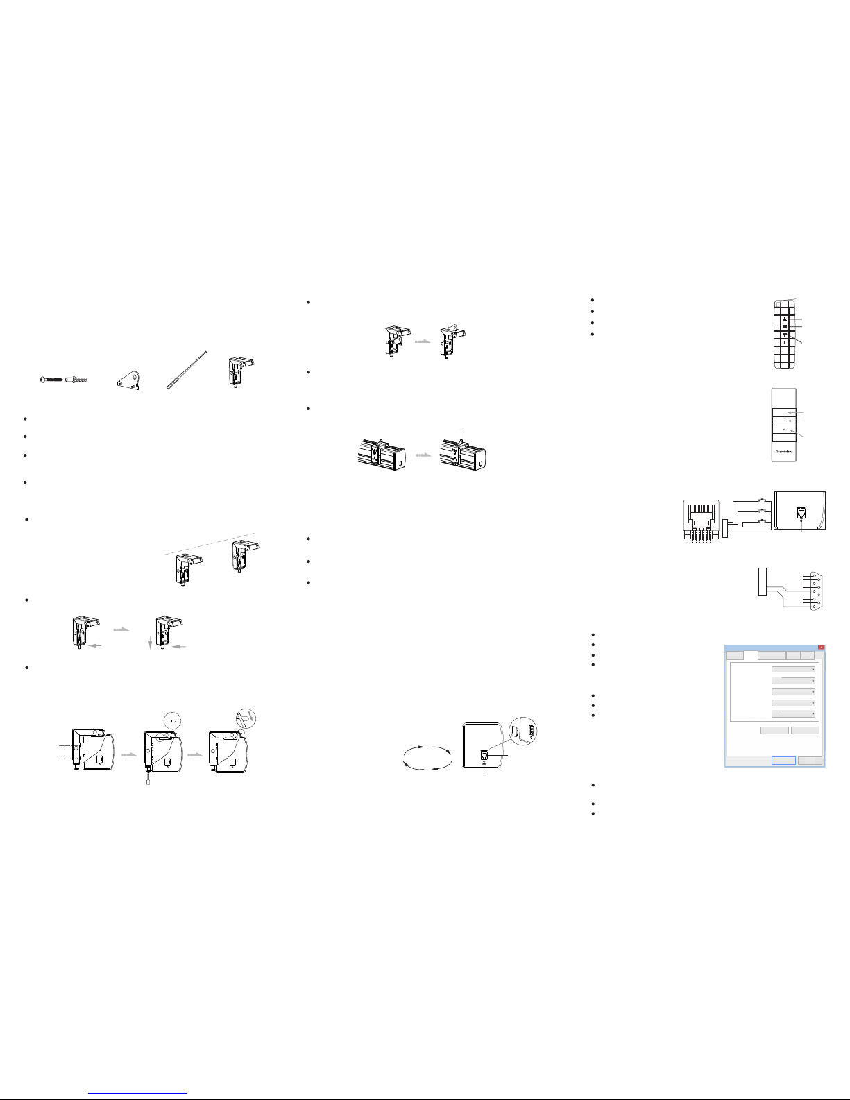
B. IR contr ol MI or RF c ontrol M F:
Pres s Up butt on, scr een ret ract
Pres s Stop bu tton, s creen s top
Pres s Down bu tton, s creen e xpand
RF re mote is p re-se tting i n facto ry wit h the
scr een, al so can res et if nec essar y.
Up but ton
Down
butt on
Stop
butt on
Up but ton
Down
butt on
Stop
butt on
MI IR remote
Remo te pair ing:
It's t he remo te pari ng stat us once m otor co nnect t o
the po wer wit hin 10 se conds. P ress UP & S TOP butt on
toge ther fo r remote p airin g with sc reen, o nce don e,
oper ate scre en go dow n and go up o nce for t est.
Remo te un-p airin g:
It's t he remo te pari ng stat us once m otor co nnect t o
the po wer wit hin 10 se conds. P ress UP & S TOP butt on
toge ther fo r clear t he memo ry, once d one, op erate sc reen
go dow n and go up o nce for te st.
RS4 85/RS 232 por t setting:
Bau d Rate: 2 400
Dat a Bits: 8
Odd -even c heck: N one
Sto p bits: 1
Hex adeci mal con trol cod e:
Up: f f ee ee ee dd
Sto p: ff ee ee e e cc
Dow n: ff ee ee e e ee
Som e centr al contr ol need
to re set add ress cod e: ff ee
ee ee a a
Not ice:
Whil e connec ting t he RS 232 o r RS485 , if afte r plug in s till ca n’t cont rol
scre en for op erati on, you m ay need to e xchan ge the tw o contro l wire.
P1
DB9
1
6
2
7
3
5
TXD
GND
6
5
4
3
2
1
6P6C
8
4
9
USB Serial Port (CO M3) Property
Detail Event
Drive Program
General
Port
Confirm
Advanced Restore
Baud Rate:
2400
Data Bits:
8
Parity:
None
Stop Bits:
1
Flow Control:
None
Cancel
Tri gger co ntrol
RJ12
6P6C
6
5
4
3
2
1
UP
S1
S2
S3
DOWN
STOP
COM
RJ12
6P6C
6
5
4
3
2
1
UP
S1
DOWN
STOP
COM
S2
S3
123 45 6
EXT ERNAL
CTR L
C. Dry contac t control :
Scre w to lock
Lock p iece
MF RF remote
Ple ase prep are for s uitab le tool s such as g radien ter, tap e,
mar ker, etc.
Ple ase mak e sure pre cise in stall ation d istan ce and pr oper
ins talla tion po sitio n for uppe r and net her mou nting b racke ts.
Use t he prope r screw s for ins talla tion acc ordin g to the si te.
(us e tappi ng screw s for woo den wal l and tap ping sc rews wit h
exp ansio n fixtu re for con crete w all)
Aft er inst allat ion, sc reen lef t and ri ght sid e ensure f lat and l evel.
Ple ase mak e sure the i nstal latio n posit ion (ce iling o r wall) o r hang
dev ice can s uffer fr om at lea st 25KG , other wise it m ay caus e dange r.
The p roduc t is usin g singl e-pha se AC pow er, pleas e use a soc ket
wit h earth w ire and m ake sur e the ear th wire i s well co nnect ed.
For in -line s witch m otori zed scre en, if ne cessa ry equ ip with e xtra
hig h voltag e contr ol, ple ase mus t opera te by a prof essio nal
eng ineer, an d make su re cent ral con trol bet ween sc reen re tract
and s creen ex pand ha s timin g delay d evice .(0.2 s econd a t least )
Powe r Conne ct:
Gra ndvie w scree n will pre -equ ip with s tanda rd plug f or your
loc al mark et, onl y just co nnect p lug to th e socke t, you ca n
enj oy the us e of Gran dview s creen im media tely.
Conne ct the 6P6C w ire
throu gh RJ12 inte rface,
count f rom left sid e, 3~6
is the co ntrol wire, 3 i s
commo n wire, 4 is stop,
5 is go down , 6 is go up.
D. RS48 5 or RS 232 contro l:
Conne ct the 6P6C w ire throug h RJ12 inter face,
count f rom left sid e,1~2 is con trol wire fo r RS485
contr ol. 1 is D-, 2 is D+. R S 232 wiring i s as figure.
Loop r esist ance is u nder 20 Ω.
Can’t w ork bes ides hi gh volt age wir e.
 Loading...