

Page 1
USER MANUAL
Rev 220906
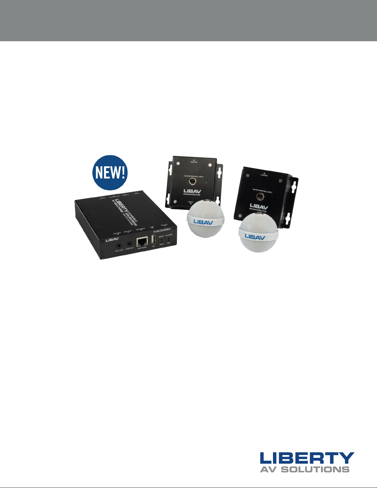
“TeamUp+” Series All-in-one
USB 2.0 Digital Audio Processor
with Two Ceiling Microphones
www.libav.com 800.530.8998
Page 2

PRODUCT OVERVIEW
Liberty’s TU-USB-CEILINGMIC2 was designed for both recording and playback for interactive
classroom and remote teaching environments. A single USB Microphone will cover up to 8
meters of acoustic radius, while two USB microphones can fully cover a 120m2 classroom
or conference room. The teacher or main presenter can speak anywhere within 2-8 meters
from either omnidirectional microphone without aecting the microphone sound pickup.
Each microphone uses a large, professional-grade acoustic transducer to capture a wide
dynamic range and can pick up a rich, full-bodied sound. The unique enclosure design
eectively suppressed large space reverberation and can capture clear undistorted audio.
PACKAGE CONTENTS
• Audio Processor
• (2) Ball Microphones
• (3) Canon Cables
• 12V Power Adapter with US, US AND EU Power Adapters
• USB Cable
2
USER MANUAL / TU-USB-CEILINGUSB2
Page 3
INSTALLING MICROPHONES
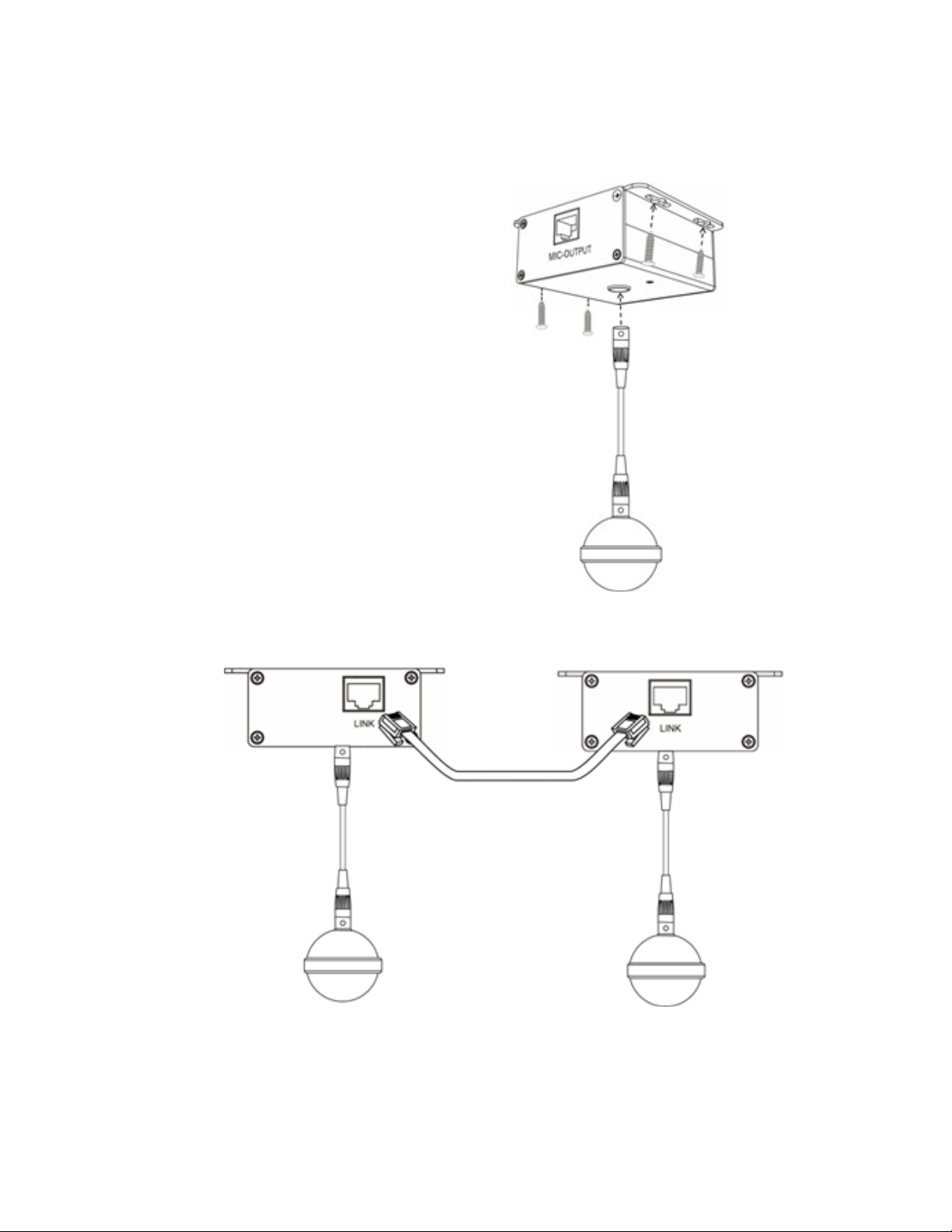
Install the canon cable between
the ceiling adapters and the
ball microphones. Install ceiling
adapter into ceiling.
USER MANUAL / TU-USB-CEILINGUSB2
Install a Category cable
between the two adapters.
This requires a 568B
termination
3
Page 4
PROCESSOR CONNECTIONS
2
3 4
1
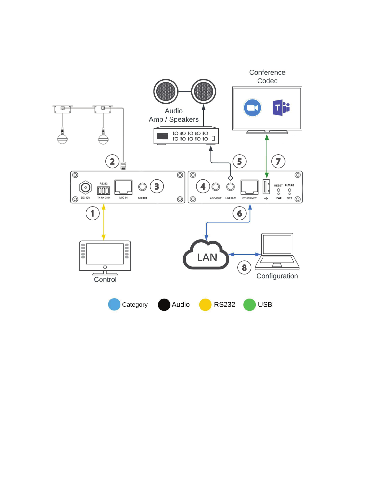
1. RS232 port, serial control interface for 3rd party control.
5
7
6
8
2. MIC IN port, balanced microphone input network interface for microphone system via Cat5e or
better.
3. AEC-REF port, dedicated echo cancellation reference signal input.
4. AEC-OUT port, dedicated echo cancellation reference signal output.
5. LINE OUT, output interface for audio reinforcement
6. ETHERNET, interface to connect to LAN / computer for system conguration
7. USB 2.0 port, connect to computer for conference codecs.
8. Conguration PC, required to set up system functions
4
USER MANUAL / TU-USB-CEILINGUSB2
Page 5
CONFIGURATION CONNECTION
1 2
4
3
5
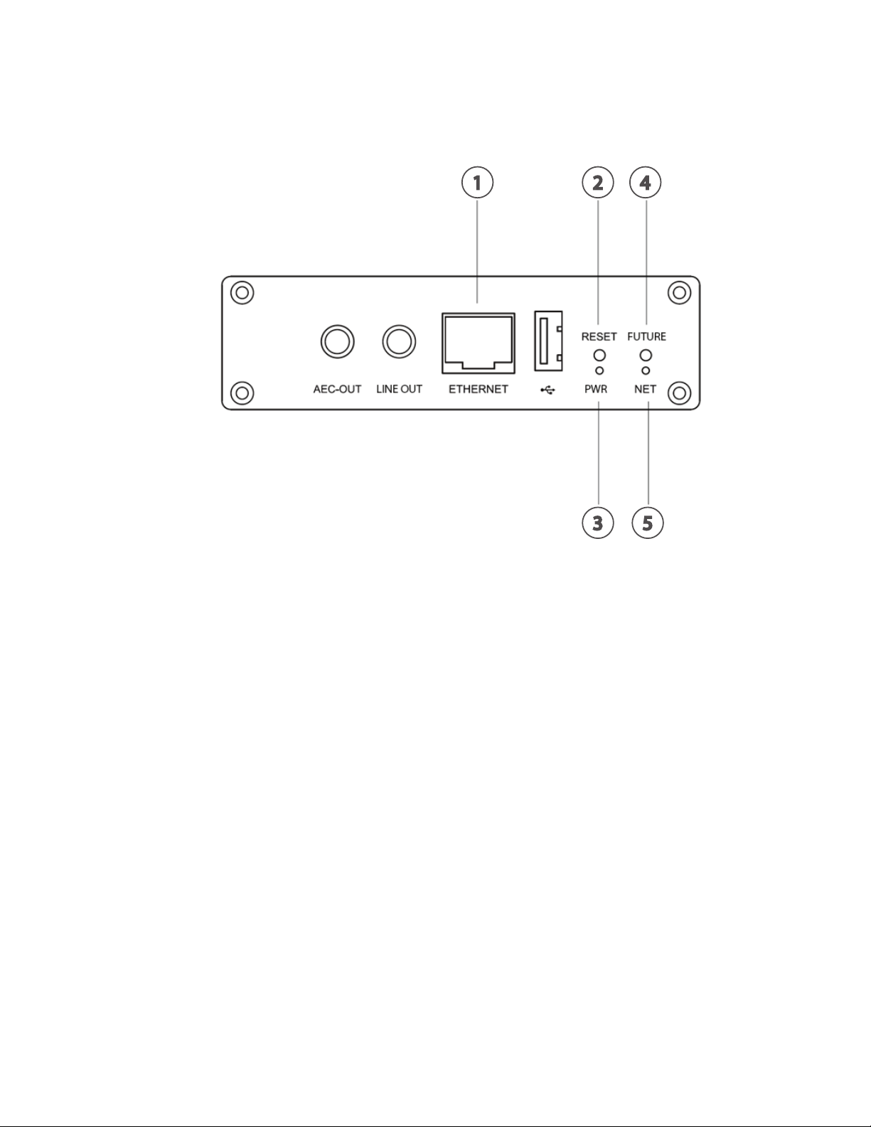
1. Connect conguration computer using Ethernet cable
• Set IP address of conguration computer to 192.168.1.0/24 Network ID
• Example: Conguration computer IP: 192.168.1.23 / Subnet 255.255.255.0
2. RESET, long press 3 seconds to restore factory settings
3. PWR LED, shows operation status, twinkle slowly means processor is working
4. For future use
5. NET LED, shows conguration connection status, light illuminates when connected
USER MANUAL / TU-USB-CEILINGUSB2
5
Page 6
SOFTWARE CONNECTION
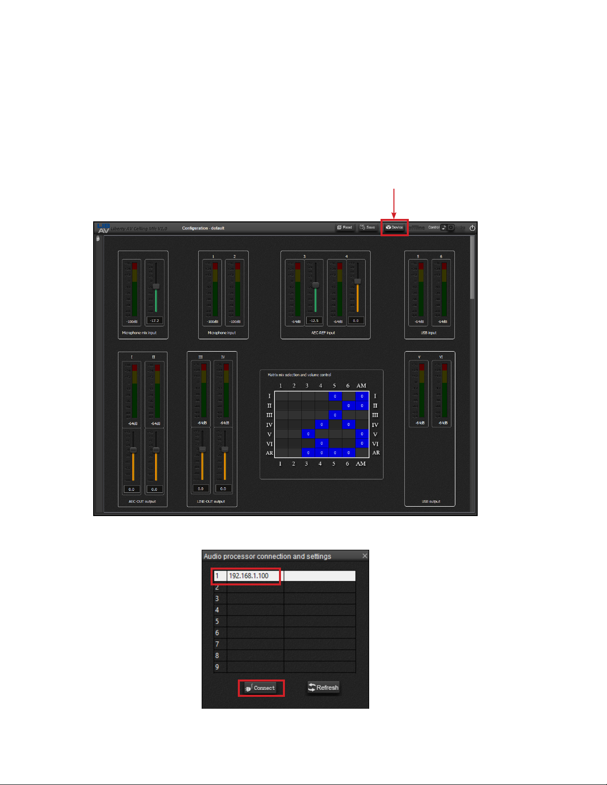
Download ‘Liberty AV Ceiling Mic Setup V1.0’ from the product page online for the TU-USB-CEILINGMIC2.
Run ‘Liberty AV Ceiling Mic Setup V1.0’ from the conguration PC connected to the system, the
screen below will appear.
Click on DEVICE
Enter in the default IP address of the unit which is 192.168.1.100, then click CONNECT.
6
USER MANUAL / TU-USB-CEILINGUSB2
Page 7
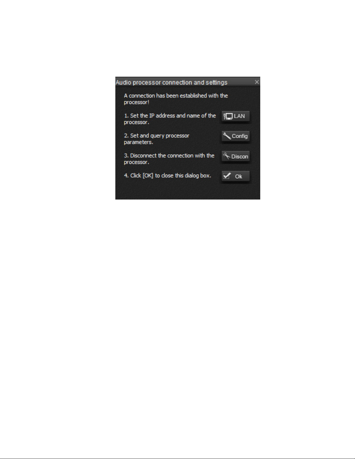
Once connected, the following menu appears.
1. To set the processor to a static IP click LAN and enter in the desired IP settings
2. To upgrade rmware and reset the unit using the software click CONFIG
3. To disconnect with the procerssor click DISCONNECT
4. Click OK to close the dialog box
USER MANUAL / TU-USB-CEILINGUSB2
7
Page 8
SOFTWARE SETTINGS
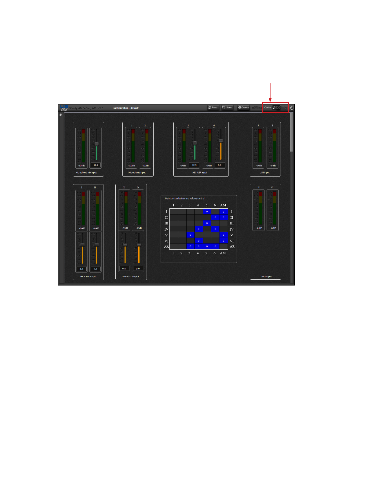
Click the Control/Design toggle to access the advance audio settings options.
Click on Control/Design
The control screen by default shows all the current input and output level settings and provides a
matrix routing option.
8
USER MANUAL / TU-USB-CEILINGUSB2
Page 9
AEC
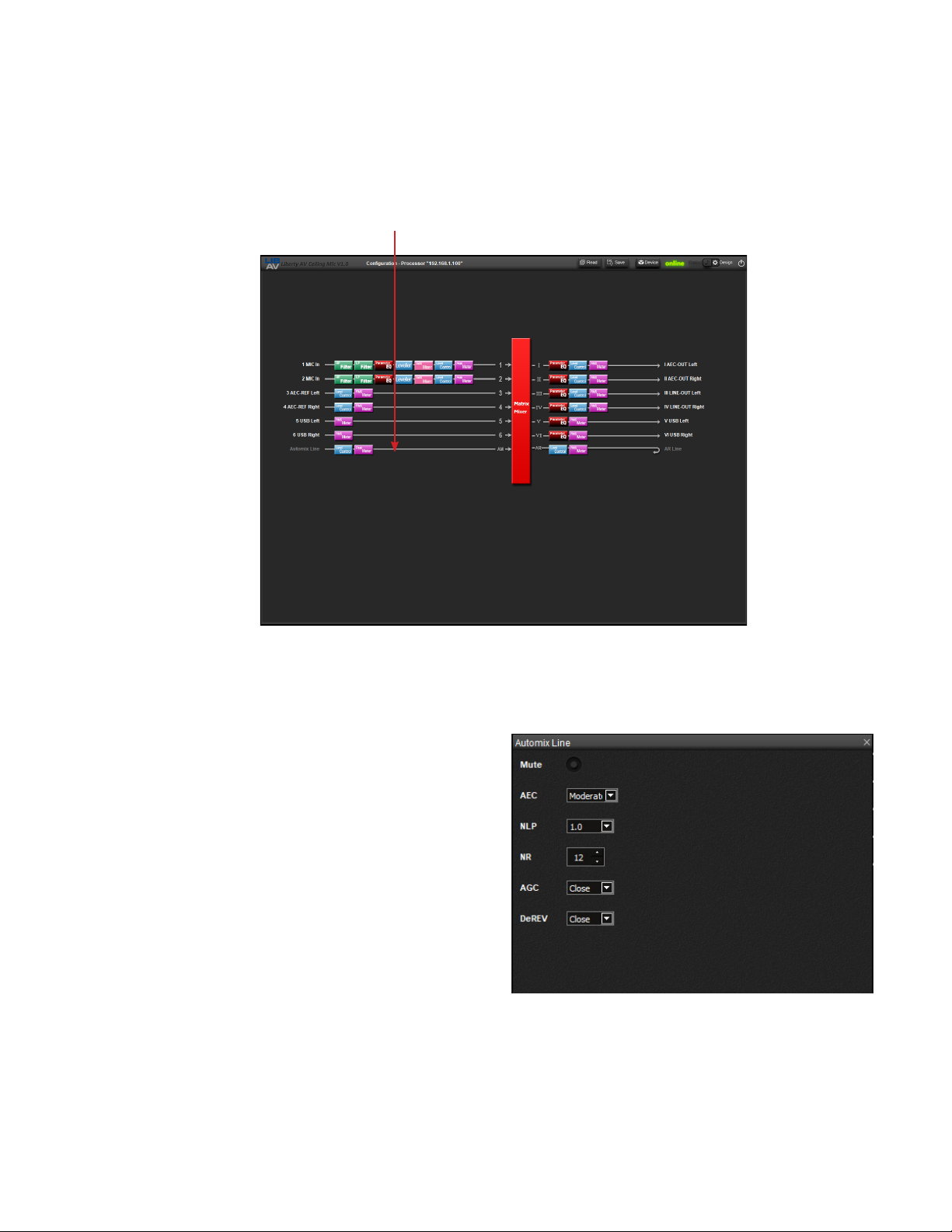
The follow screen appears, double click on the Automix Line to adjust AEC settings.
Double Click on Control/Design
The follow screen appears, below are explanations of the AEC settings, choose the desired settings
from the drop down options in the menu.
1. MUTE - Automix Line mute toggle
2. AEC - Auto Echo Cancellation settings
3. NLP - Non linear processing settings
4. NR - Noise Reductions settings
5. AGC - Automatic gain control settings
6 - DeREV - Dereverberation Settings
1
2
3
4
5
6
USER MANUAL / TU-USB-CEILINGUSB2
9
Page 10
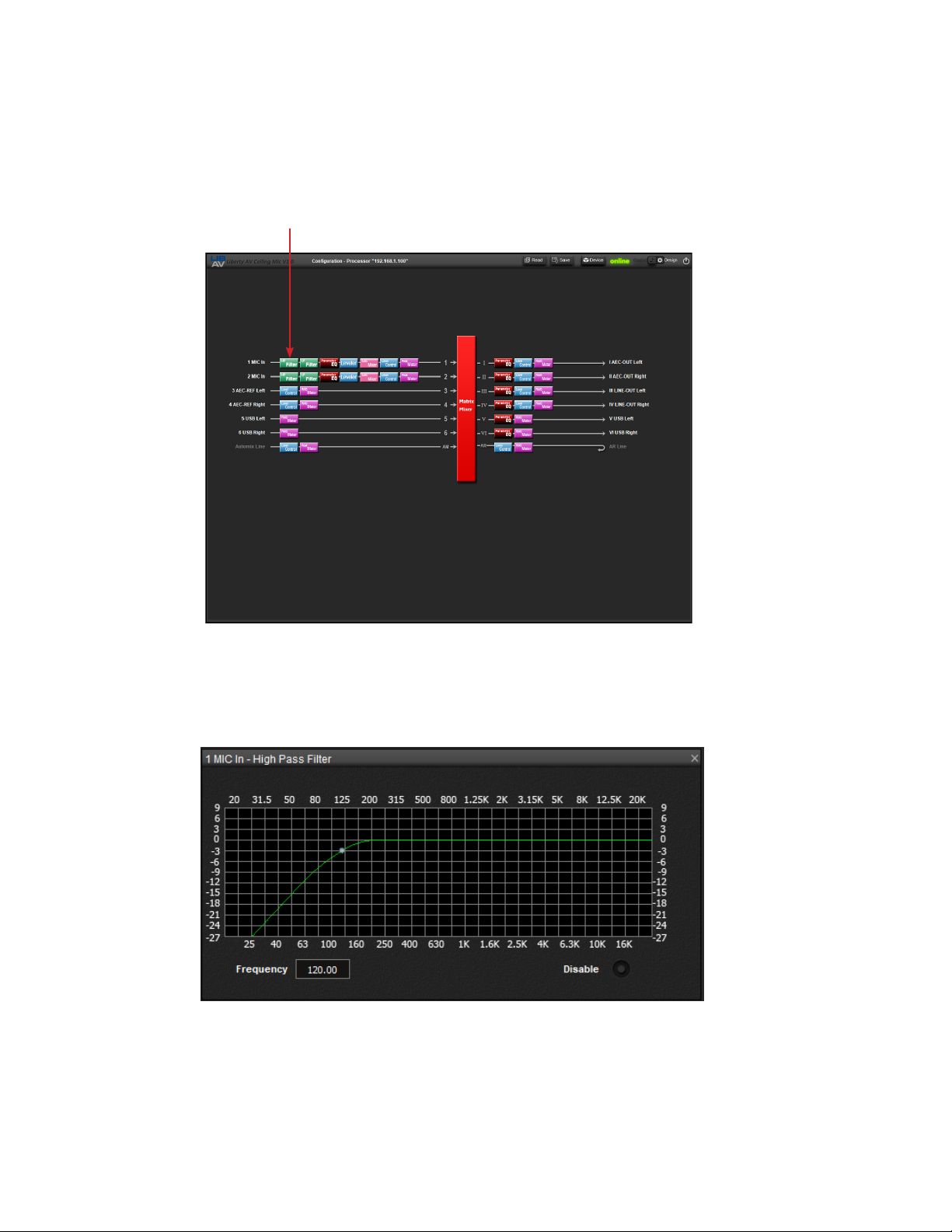
HIGH PASS FILTER
Navigate to the design page, double click on the HP Filter to adjust high pass lter settings.
Double Click on HP Filter
The following screen appears, adjust lter as needed by clicking and dragging the graph or enter in
the frequency.
10
USER MANUAL / TU-USB-CEILINGUSB2
Page 11
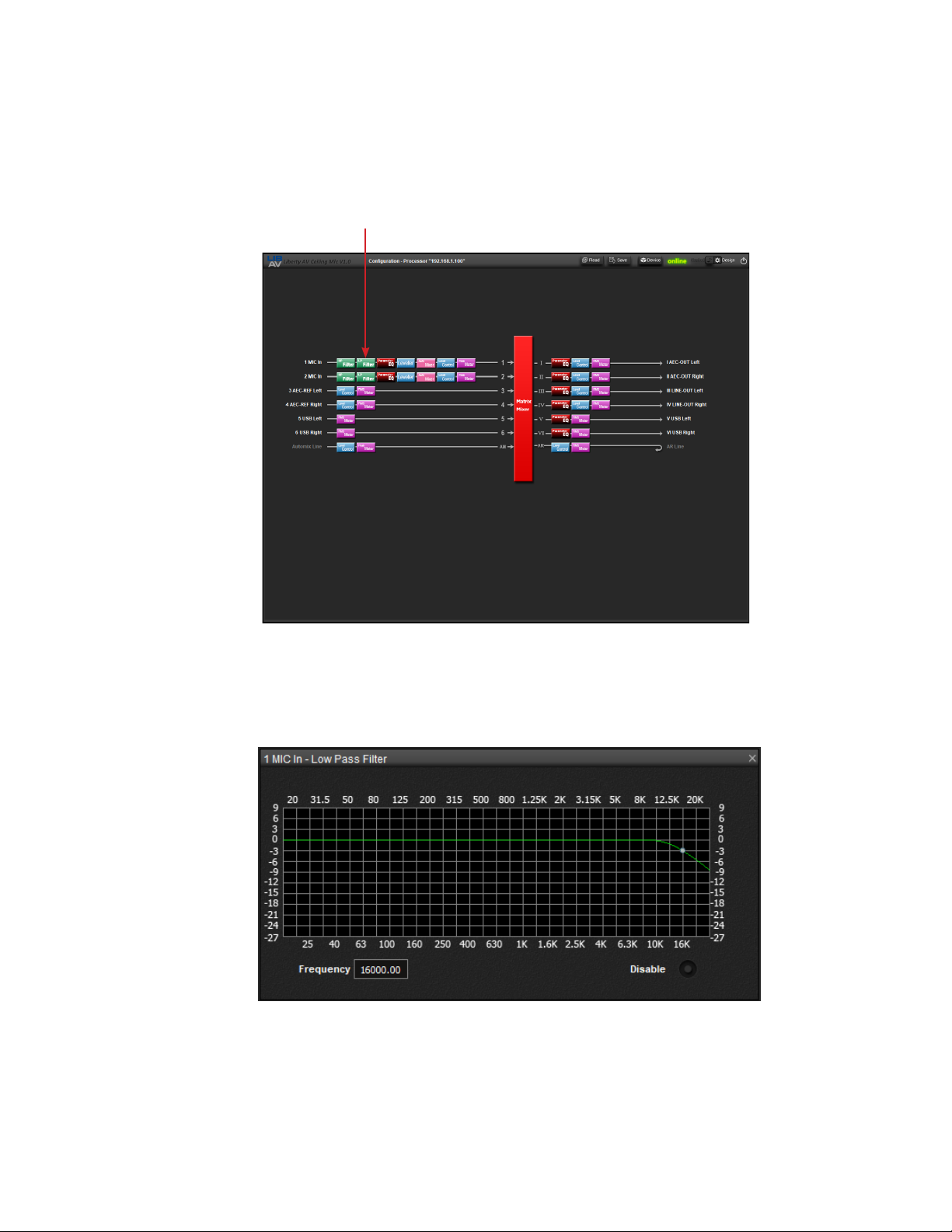
LOW PASS FILTER
Navigate to the design page, double click on the LP Filter to adjust low pass lter settings.
Double Click on LP Filter
The following screen appears, adjust lter as needed by clicking and dragging the graph or enter in
the frequency.
USER MANUAL / TU-USB-CEILINGUSB2
11
Page 12
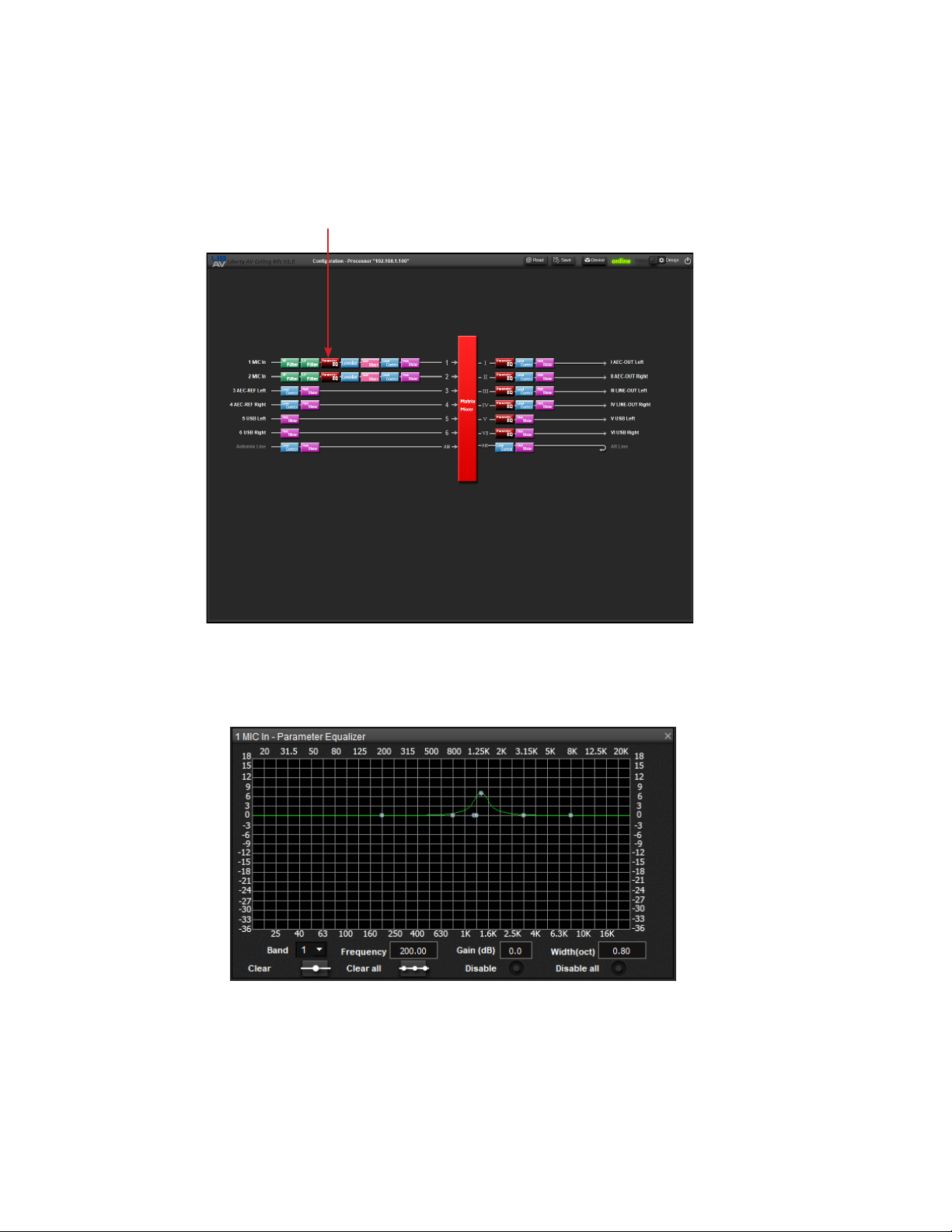
PARAMETRIC EQ
Navigate to the design page, double click on the Parametric EQ to adjust the equalization of the signal.
Double Click on Parametric EQ
The following screen appears, adjust EQ settings as needed.
12
USER MANUAL / TU-USB-CEILINGUSB2
Page 13
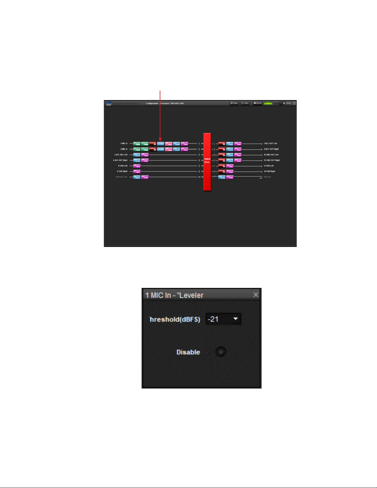
LEVELER
Navigate to the design page, double click on the Leveler to adjust the compression threshold of the
signal, by default the compression ratio is 10:1.
Double Click on Leveler
The following screen appears, adjust the compression threshold settings as needed.
USER MANUAL / TU-USB-CEILINGUSB2
13
Page 14
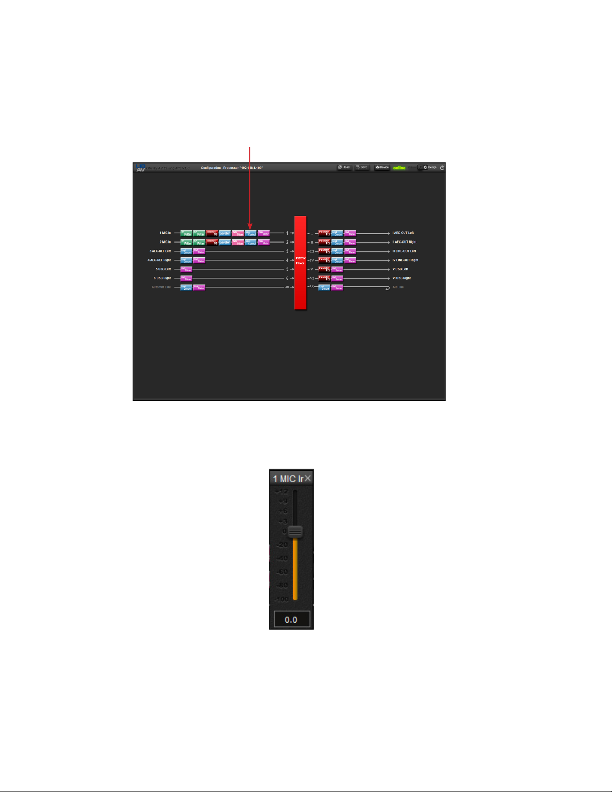
LEVEL CONTROL
Navigate to the design page, double click on the Level Control to view and adjust the level of the
signal.
Double Click on Level Control
The following meter screen appears.
14
USER MANUAL / TU-USB-CEILINGUSB2
Page 15
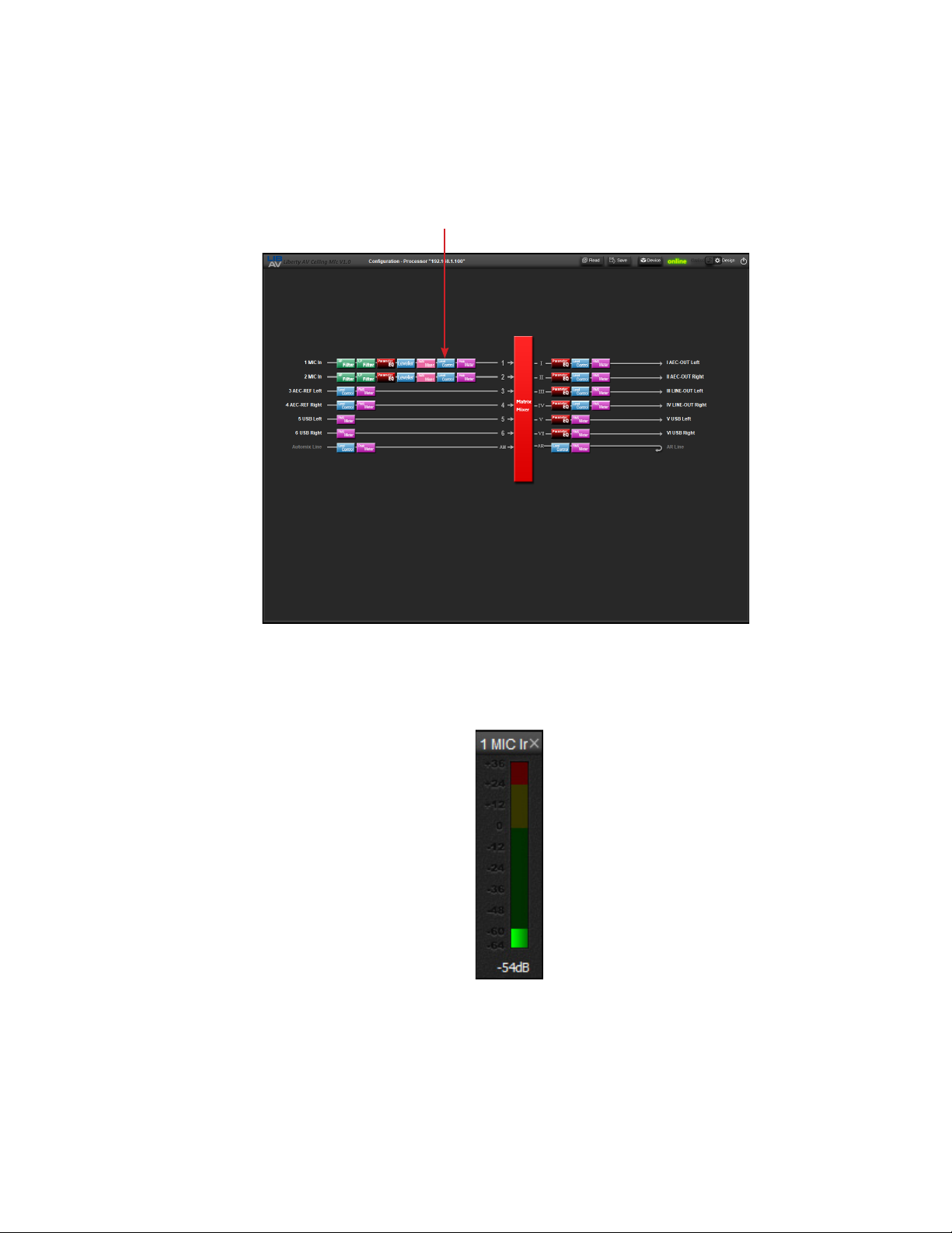
PEAK METER
Navigate to the design page, double click on the Peak Meter to view the level of the signal.
Double Click on Peak Meter
The following meter screen appears.
USER MANUAL / TU-USB-CEILINGUSB2
15
Page 16
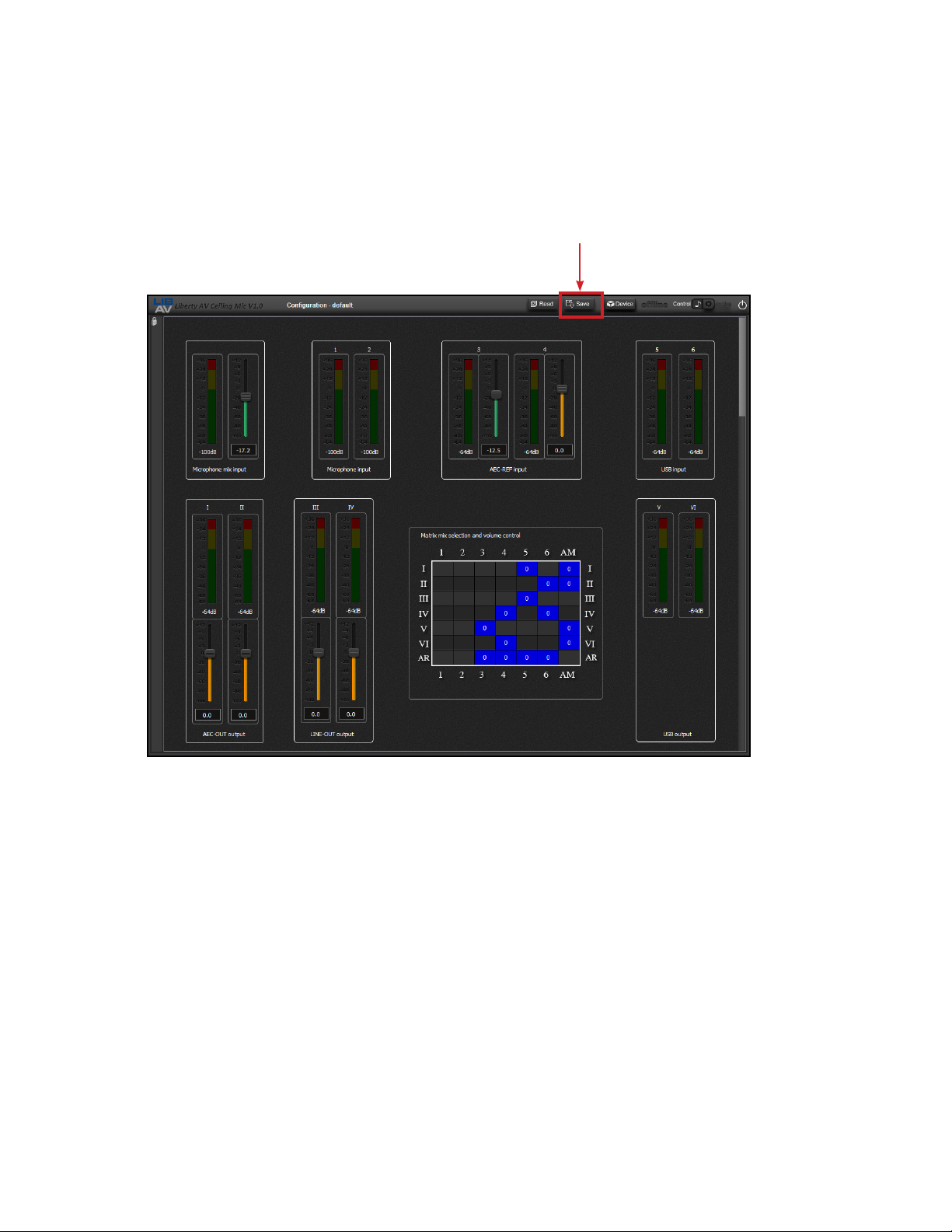
SAVE CONFIGURATION
Click Save to save the current conguration le on your local PC.
Click Save
16
USER MANUAL / TU-USB-CEILINGUSB2
Page 17
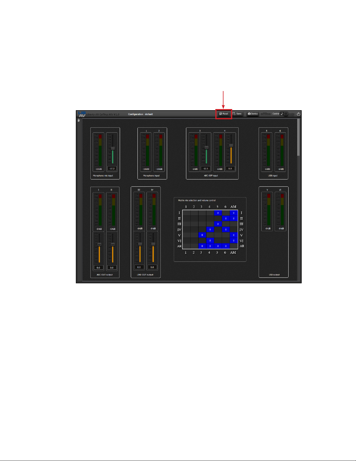
LOAD CONFIGURATION
Click Load to load a conguration le from your local PC.
Click Load
USER MANUAL / TU-USB-CEILINGUSB2
17
Page 18
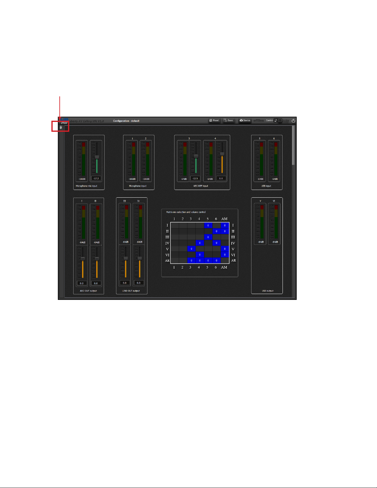
CUSTOMIZE CONTROL SCREEN UI
Click the LOCK icon to adjust the GUI as desired, click again to the lock the GUI in place.
Click Lock Icon
18
USER MANUAL / TU-USB-CEILINGUSB2
Page 19
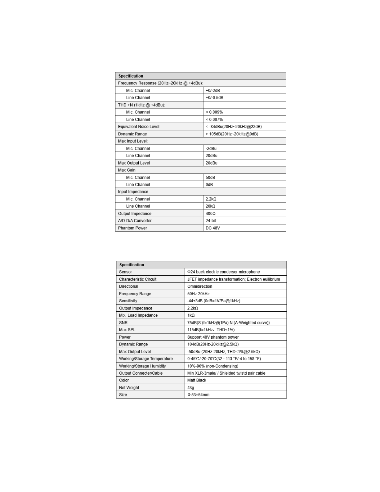
PROCESSOR
TECHNICAL SPECIFICATIONS
MICROPHONE
USER MANUAL / TU-USB-CEILINGUSB2
19
Page 20

Thank you for your purchase.
For technical support please call our
toll-free number at 800-530-8998
or email us at [email protected]
www.libav.com 800-530-8998
 Loading...