

Page 1

TU-HUC42-TX/RX
Owner's Manual
TeamUp+ S
Collaboration Switcher / Extender / Hub
with uncompressed 4K60 over HDBaseT
3.0
eries 18G BYOM
www.libav.com 800.530.8998
Page 2
Thank you for purchasing this product
For optimum performance and safety, please read these instructions carefully
before connecting, operating or adjusting this product. Please keep this manual
for future reference.
Surge protection device recommended
This product contains sensitive electrical components that may be damaged
by electrical spikes, surges, electric shock, lighting strikes, etc. Use of surge
protection systems is highly recommended in order to protect and extend the
life of your equipment.
Caution
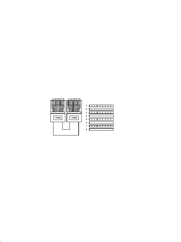
The product requires the use of UTP connectors. Please connect in direct
interconnection method and do not cross connect.
White and Orange
Orange
White and Green
Blue
White and Blue
Green
White and Brown
Brown
Direct Interconnection Method
Table of Contents
1. Introduction............................................................................................
2. Features..................................................................................................
3. Package Contents................................................................................
4. Specifications........................................................................................
5. Operation Controls and Functions......................................................
5.1 Transmitter Top Panel......................................................................
5.2 Transmitter Front & Rear Panel........................................................
5.3 Receiver Top Panel.........................................................................
5.4 Receiver Front & Rear Panel...........................................................
6. Web GUI Operation Guide...................................................................
7. API Commands......................................................................................
8. Application Example............................................................................
1
1
2
3
5
5
6
8
9
10
18
25
Page 3

1. Introduction
This is a 2x1+1 (TX only) or 4x2 (TX/RX kit) multi-format A/V matrix with
HDBaseT 3.0 extension that supports uncompressed video resolutions up to
4K@60Hz 4:4:4 8bit deep color. It is HDCP 2.2 / 2.3 compliant and has a built
in USB 3.0 switching hub with 8 total USB 3.0 client ports and 3 USB host
ports for control and integration of USB devices such as USB cameras/mic.
The transmitter features two video inputs: one HDMI and one USB-C. The
USB-C input supports video, data (USB host), and power charging up to 60W
(for charging, the included power supply must be connected on the TX side).
There is a 4-port USB 3.0 client hub built with 2 USB 3.0 host ports (one is
USB-C port). Ourputs include HDBaseT3.0 & mirrored HDMI.
The receiver features 3x2 matrix outputs: one HDBaseT 3.0 input, two local
HDMI inputs and two HDMI outputs. The built-in HDBaseT 3.0 extension
supports long distance transport of audio, video, RS-232 and High-Speed
USB 2.0 signals up to 300Mbps up to 70 meters using one category cable.
The receiver also includes a USB 3.0 switching hub with 4 USB 3.0
clients. This product is ideal for software-based video teleconference rooms
that require the consolidation and sync of A/V and USB signals from a laptop
or room PC.
The product can be controlled via top panel buttons or API commands using
RS-232 or TCP/IP. A web server / GUI is built into the TX unit that features A/V
and USB switching control, display control, input EDID & HDCP management.
Control options include the ability to automate the display power by using
RS-232/CEC commands whenever a video signal is introduced using any A/V
input and display power OFF after a specified amount of time has passed
when no video signal or switching activity is present. For a complete list of
programming commands, please refer to page 17 of this manual.
2. Features
• HDMI 2.0b and HDCP 2.2 compliant
• HDBaseT 3.0 VS300R chipset
• Uncompressed video signal transmission distance can be extended up to
230ft/70m for 4K@30Hz, or 131ft/40m for 4K@60Hz
• HDR, HDR10, HDR10+, Dolby Vision LLM, HLG pass-through
• TX: HDMI and USB-C 2x1 inputs, two USB 3.0 hosts and four USB 3.0
clients
1 / 25
Page 4
• RX: HDBaseT and 2 local HDMI inputs, 3x2 matrix outputs with one
USB 3.0 host and four USB 3.0 clients
• 1x8 USB 3.0 hub with 8 USB 3.0 clients, each client output power can
be on/off control independently
• USB-C supports ALT-DP mode for A/V, USB 3.0 data and power
charging up to 60W
• Supports bidirectional POC (power over cable), when TX or RX gets
power, the other end does not need an external power supply
• Supports 3.5mm analog audio de-embedding at TX and RX
• Supports 4K to 1080p downscaling features on all HDMI outputs, no
frame rate conversion
• RS-232 passthrough and guest-mode control
• CEC and RS-232 control external display device ON/OFF
• Advanced EDID management
• Top panel buttons, RS-232 and TCP/IP control (TX built-in TCP/IP port
for API and Web GUI)
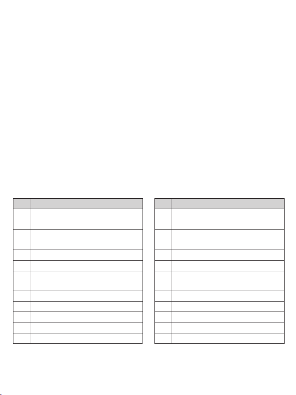
3. Package Contents
Qty Item
HDBT 3.0 4K60 Extender
1
(Transmitter)
3-pin Phoenix Connector
1
(3.81mm, male)
Machine Screw (KM3, 4mm)
4
Mounting Ear
2
24V/3.75A Desktop Power
1
Supply (Locking)
1
AC Power Cord (UK Standard)
1
AC Power Cord (EU Standard)
1
AC Power Cord (AU Standard)
1
AC Power Cord (US Standard)
1
User Manual
Qty Item
HDBT 3.0 4K60 Extender
1
(Receiver)
3-pin Phoenix Connector
1
(3.81mm, male)
Machine Screw (KM3, 4mm)
4
2
Mounting Ear
or
24V/2.7A Desktop Power
1
Supply (Locking)
1
AC Power Cord (UK Standard)
1
AC Power Cord (EU Standard)
1
AC Power Cord (AU Standard)
1
AC Power Cord (US Standard)
1
User Manual
2 / 25
Page 5
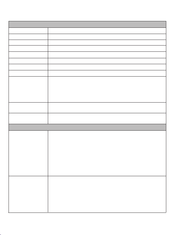
4. Specifications
Technical
HDMI Compliance HDMI 2.0b
HDCP Compliance HDCP 2.2
Video Bandwidth 18Gbps
Video Resolution
USB Bandwidth
Color Space RGB, YCbCr 4:4:4, YCbCr 4:2:2, YCbCr 4:2:0
Color Depth
HDR
Audio Formats
Transmission
Distance
ESD Protection
Connection
Transmitter
Receiver
Up to 4K@60Hz 4:4:4
Up to 300Mbps
8/10/12bit
HDR, HDR10, HDR10+, Dolby Vision, HLG
HDMI/USB-C Pass-through:
LPCM, Dolby Digital/Plus/EX, Dolby True HD, DTS, DTS-EX,
DTS-96/24, DTS High Res, DTS-HD Master Audio, DSD
Audio De-embedding:
LPCM 2CH only
4K60:
131ft/40m (CAT6A/7)
4K30:
230ft/70m (CAT6A/7)
Human body model — ±8kV (Air-gap discharge) &
±4kV (Contact discharge)
Input: 1 x HDMI IN [Type A, 19-pin female]
1 x USB-C IN [USB Type C, 24-pin female]
Output: 1 x HDMI LOOP OUT [Type A, 19-pin female]
1 x HDBaseT OUT [RJ45, 8-pin female]
1 x AUDIO OUT [3.5mm audio jack]
Control: 1 x RS-232 [3pin-3.81mm Phoenix jack]
1 x F/W [Micro USB, 5-pin female]
1 x HOST [USB 3.0 Type B, 9-pin female]
4 x USB DEVICE [USB 3.0 Type A, 9-pin female]
1 x TCP/IP [RJ45]
Input: 2 x HDMI IN [Type A, 19-pin female]
1 x HDBaseT IN [RJ45, 8-pin female]
Output: 2 x HDMI OUT [Type A, 19-pin female]
1 x AUDIO OUT [3.5mm audio jack]
Control: 1 x RS-232 [3pin-3.81mm Phoenix jack]
1 x F/W [Micro USB, 5-pin female]
1 x HOST [USB 3.0 Type B, 9-pin female]
4 x USB DEVICE [USB 3.0 Type A, 9-pin female]
3 / 25
Page 6
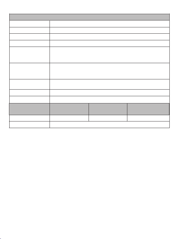
Mechanical
Metal EnclosureHousing
Color
Dimensions
Weight
Power Supply
Power Consumption
(Max)
Operating
Temperature
Storage Temperature
Relative Humidity
Resolution /
Cable Length
HDMI IN / OUT 26ft / 8M
The use of “Premium High Speed HDMI” cable is highly recommended.
Black
Transmitter / Receiver: 208mm [W] x 107mm [D] x 27mm [H]
Transmitter: 616g, Receiver: 585g
Input: AC 100 - 240V 50/60Hz
Output: TX: DC 24V/3.75A; RX: DC 24V/2.7A
(US/EU standard, CE/FCC/UL certified)
TX: 97.6W (60W USB-C charging and full power supply to 4x
USB devices)
RX: 31.12W (full power supply to 4x USB devices)
32 - 104°F / 0 - 40°C
-4 - 140°F / -20 - 60°C
20 - 90% RH (no condensation)
4K60 Feet / Meters
4K24 Feet / Meters
39ft / 12M
1080P60 Feet / Meters
50ft / 15M
4 / 25
Page 7
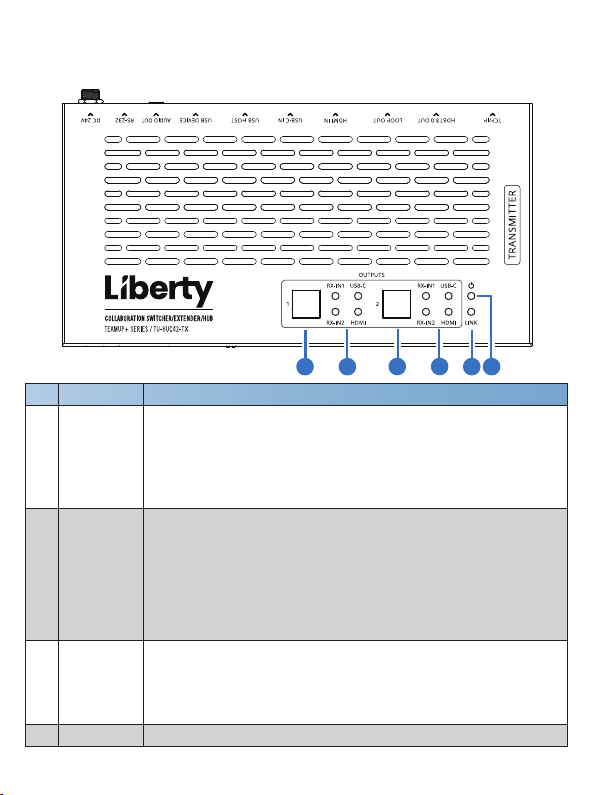
5. Operation Controls and Functions
5.1 Transmitter Top Panel
1 32 4
Name Function Description
No.
Input source selection button for the HDMI OUT 1/2 port of the
OUTPUTS
1/2 selection
1
button
OUTPUTS
1/2 LEDs
2
(Green)
LINK LED
3
(Green)
4
Power LED Red LED indicates that the Transmitter is powered on.
Receiver.
Note: There is a linkage relation between the HDMI IN and USC-C
IN port, when one of them is selected as the input channel for HDMI
OUT 1/2. For example, when HDMI OUT 1 selects USB-C IN as the
input channel, HDMI OUT 2 will switch to USB-C IN simultaneously.
HDMI LED: When the HDMI IN port of Transmitter is selected as
the input channel for HDMI OUT 1/2, the HDMI LED will be on.
USB-C LED: When the USB-C IN port of Transmitter is selected
as the input channel for HDMI OUT 1/2, the USB-C LED will be on.
RX-IN1 LED: When the HDMI IN 1 port of Receiver is selected as
the input channel for HDMI OUT 1/2, the RX-IN1 LED will be on.
RX-IN2 LED: When the HDMI IN 2 port of Receiver is selected as
the input channel for HDMI OUT 1/2, the RX-IN1 LED will be on.
▪ Light on: Transmitter and Rec
▪ Light flashing: Transmitter and Receiver have poor connection
status or connected to the same device.
▪ Light off: Transmitter and Receiver are not connected, or the
system is powered off.
5 / 25
1 2
eiver have good connection status.
Page 8
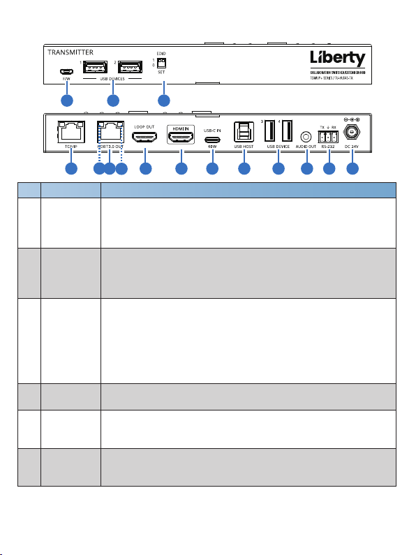
5.2 Transmitter Front & Rear Panel
1
6
5 9 10 11 12 134 8
7
Name Function Description
No.
32
Firmware upgrade port, which can be used to upgrade the MCU
1
F/W port
(default) or Valens firmware through API commands switching.
Note: The RS module requires approximately 40s~50s to start, and
the MCU version number can only be read after startup.
Four USB extension ports, connected to mouse, keyboard, USB
2
USB
DEVICES
camera or other USB devices.
Note: The local end supports USB 3.0 transfer rate, but the remote
end only supports USB 2.0 transfer rate.
Used for EDID setting:
00- Copy HDMI OUT 1 port sink EDID (as factory default)
01- 4K30 4:4:4 2CH
3
EDID DIP
switch
10- 1080p60 4:4:4 2CH
11- 1200p60 4:4:4 2CH
Note: The DIP switch operation is available only after switching to
the DIPSWITCH mode through API commands or Web operation.
TCP/IP port
4
HDBT3.0
5
OUT port
Data Signal
Indicator
6
(Yellow)
TCP/IP port, connected to PC or router. By default, the dynamic IP
address is used, and the IP address can be obtained by command.
HDBaseT output port, connected to the HDBT3.0 IN port of
Receiver with a CAT 6A/7 cable. It is used for various signals
pass-through.
▪ Illuminating: HDMI signal with HDCP.
▪ Flashing: HDMI signal without HDCP.
▪ Dark: No HDMI signal.
2
14
6 / 25
Page 9
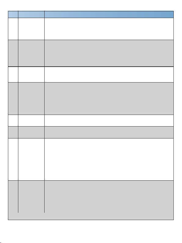
No.
Name Function Description
Link Signal
Indicator
7
(Green)
LOOP OUT
8
port
HDMI IN
9
port
USB-C IN
10
port
USB HOST
11
port
AUDIO OUT
12
port
RS-232 port
13
14
DC 24V
▪ Illuminating: Transmitter and Receiver have good connection status.
▪ Flashing: Transmitter and Receiver have poor connection status.
▪ Dark: Transmitter and Receiver are not connected.
HDMI signal loopout port, connected to HDMI display device, such
as TV or monitor. Through API commands or Web GUI operation,
users can set this port to loopout the signals from HDMI IN port or
USB-C IN port, and control the connected TV to power on/off or
increase/decrease the volume.
HDMI signal input port, connected to HDMI source device. Users
can control the operation of the connected source device through
API commands.
(1) USB-C signal input port, connected to source device, with the
highest resolution of 4K30.
(2) USB-C HOST port, connected to PC for extending the USB
ports of TX or RX.
(3) Charging port for external USB-C devices, with a maximum
power supply of 60W.
USB HOST port, connected to PC for extending the USB ports of
TX or RX.
Analog audio output port, which is used for audio de-embedding
output.
RS-232 serial port with following three functions:
(1) Pass through external serial port commands to the RS-232 port
of the HDBaseT Receiver.
(2) Receive API commands to control the Extender.
(3) Send API commands to control external devices (when the
Transmitter is used alone).
Note: The above points 1 and 2 can be used simultaneously, while
points 3 is used separately.
Power input port, connected to 24V DC power supply.
Note:
(1) The USB-C IN port can provide power for the connected USB-
C device only when the Transmitter is connected to power
supply.
(2) When TX/RX is fully loaded, the Receiver also needs to be
connected to a 24V/3.75A power supply.
7 / 25
Page 10
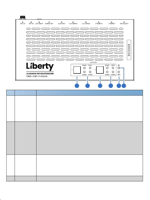
5.3 Receiver Top Panel
Name Function Description
No.
Input source selection button for the HDMI OUT 1/2 port of the
OUTPUTS
1/2 selection
1
button
OUTPUTS
1/2 LEDs
2
(Green)
LINK LED
3
(Green)
4
Power LED Red LED indicates that the
Receiver.
Note: There is a linkage relation between the HDMI IN and USC-C
IN port, when one of them is selected as the input channel for HDMI
OUT 1/2. For example, when HDMI OUT 1 selects USB-C IN as the
input channel, HDMI OUT 2 will switch to USB-C IN simultaneously.
HDMI LED: When the HDMI IN port of Transmitter is selected as
the input channel for HDMI OUT 1/2, the HDMI LED will be on.
USB-C LED: When the USB-C IN port of Transmitter is selected
as the input channel for HDMI OUT 1/2, the USB-C LED will be on.
RX-IN1 LED: When the HDMI IN 1 port of Receiver is selected as
the input channel for HDMI OUT 1/2, the RX-IN1 LED will be on.
RX-IN2 LED: When the HDMI IN 2 port of Receiver is selected as
the input channel for HDMI OUT 1/2, the RX-IN1 LED will be on.
▪ Light on: Transmitter and Rec
▪ Light flashing: Transmitter and Receiver have poor connection
status or connected to the same device.
▪ Light off: Transmitter and Receiver are not connected, or the
system is powered off.
8 / 25
1 32 4
Receiver
1 2
eiver have good connection status.
is powered on.
Page 11
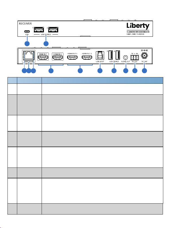
5.4 Receiver Front & Rear Panel
1
4
Name Function Description
No.
1
F/W port
2
5
6
7 8 9 103
Firmware upgrade port, which can be used to upgrade the MCU
(default) or Valens firmware through API commands switching.
Four USB extension ports, connected to mouse, keyboard, USB
2
USB
DEVICES
camera or other USB devices.
Note: The local end supports USB 3.0 transfer rate, but the remote
end only supports USB 2.0 transfer rate.
HDBT3.0
3
IN port
Data Signal
Indicator
4
(Yellow)
Link Signal
Indicator
5
(Green)
HDMI IN
6
1/2 port
HDBaseT input port, connected to the HDBT3.0 OUT port of
Transmitter
with a CAT 6A/7 cable. It is used for various signals
pass-through.
▪ Illuminating: HDMI signal with HDCP.
▪ Flashing: HDMI signal without HDCP.
▪ Dark: No HDMI signal.
▪ Illuminating: Transmitter and Receiver have good connection status.
▪ Flashing: Transmitter and Receiver have poor connection status.
▪ Dark: Transmitter and Receiver are not connected.
HDMI signal input port, connected to HDMI source device.
HDMI signal output port, connected to HDMI display device, such
HDMI OUT
7
1/2 port
as TV or monitor. The input source can be selected through top
panel buttons, API commands or Web GUI operation. Beside,
through API commands or Web GUI operation, users can control
the connected TV to power on/off or increase/decrease the volume.
USB HOST
8
port
USB HOST port, connected to PC for extending the USB ports of
TX or RX.
9 / 25
2
11
Page 12
Name Function DescriptionNo.
AUDIO OUT
9
port
RS-232 port
10
11
DC 24V
Analog audio output port, which is used for audio de-embedding
output.
RS-232 serial port with follcwing two functions:
(1) Pass through external serial port commands to the RS-232 port
of the HDBaseT Transmitter.
(2) Send API commands to control external devices (when the
Transmitter and Receiver is used together).
Note: The above points 1 and 2 can be used simultaneously.
Power input port, connected to 24V DC power supply.
Note: When TX/RX is fully loaded, the Receiver also needs to
be connected to a 24V/2.7A power supply.
6. Web GUI Operation Guide
The extender can be controlled & settings modified by Web GUI. The
operation method is shown as below:
Step 1: Get the current IP Address.
The default IP address of the extender is 192.168.0.178 (when the system is
not connected to a router). You can get the current extender IP address via
API command control. Send the ASCII command “GetIPv4Address” through
a Serial Command tool, then you’ll get the current IP address (The IP address
is variable, depending on what the specific machine returns).
For the details of API command control, please refer to page 18.
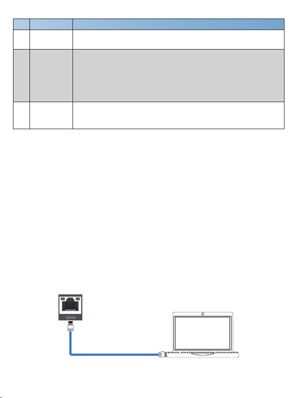
Step 2: Connect the TCP/IP port of the extender to a PC with an UTP cable
(as shown in the following figure), and set the IP address of the PC to be in
the same network segment with the extender.
LAN
LAN
10 / 25
PC
Page 13
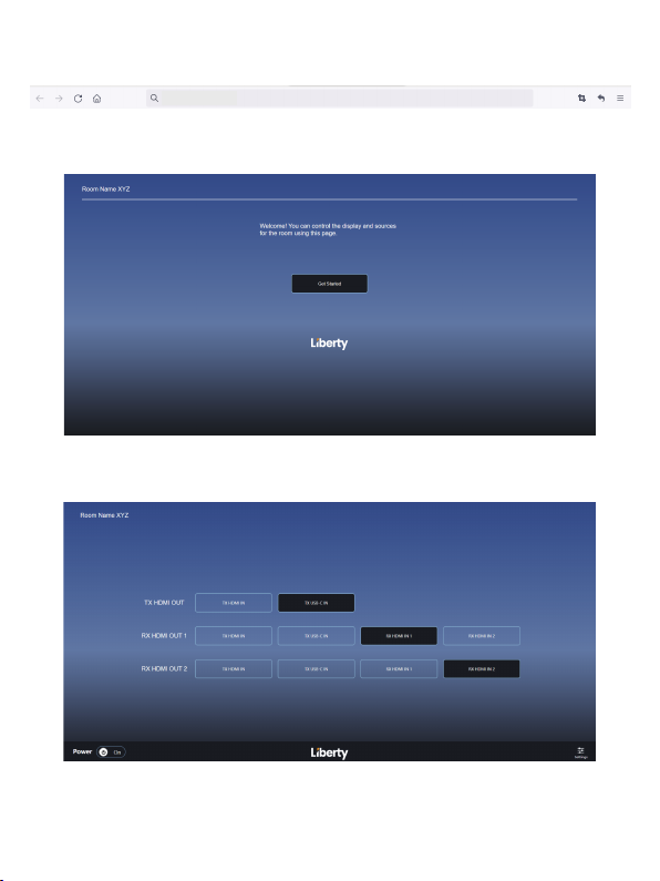
Step 3: Input the current IP address of extender into your browser on the PC
to enter Web GUI interface.
http://192.168.0.178
After entering the Web GUI page, there will be a visitor interface, as shown
below.
Click “Get Started” or wait for 3 seconds to enter the operation interface, as
shown below.
You can do the following operations on this page:
① TX HDMI OUT: Click to select the signal source for the loop output of
transmitter.
11 / 25
Page 14
② RX HDMI OUT 1: Click to select the signal source for the output of
receiver’
③ RX HDMI OUT 2: Click to select the signal source for the output of
receiver’
④ Click the Power button to power on/off the extender.
⑤ Click the Settings icon to enter the login interface.
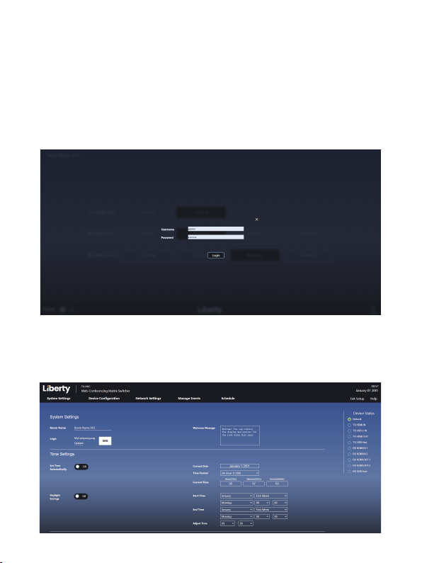
Step 4: Click the Settings icon to enter the login interface, as shown below.
Input the default username “admin” and password “password”, then click
“Login” to enter the operation interface.
s HDMI OUT 1 port.
s HDMI OUT 2 port.
■ System Settings Page
12 / 25
Page 15

System Settings
① Room Name: You can modify the name.
② Logo: Click “IMG” to import an image to the welcome interface.
③ Welcome Message: You can modify the slogan of the welcome interface.
④ Device Status: System status, displaying each port’s connection status.
Time Settings
① Set Time Automatically: You can turn on/off the function of “Set time
automatically”. When the function is turned on, you can get the date and time
through the server. When the function is turned off, you can set the date and
time of the system through the options on the right.
② Daylight Savings: You can turn on/off the function of “Daylight Savings”.
When the function is turned on, you can set the daylight time through the
options on the right.
Update Password:
You can modify the username and password.
System Configuration
① Configuration Name: You can name the configuration table.
② Update: Click to import the configuration table to the Manage Events
interface.
③ Download: Click to export the configuration table from the Manage Events
interface.
④ Firmware: Display the firmware version. You can click “Update” to update
the firmware.
⑤ Factory Reset: Click to restore all settings to factory default settings.
After setting up, click “Save” to take effect.
13 / 25
Page 16
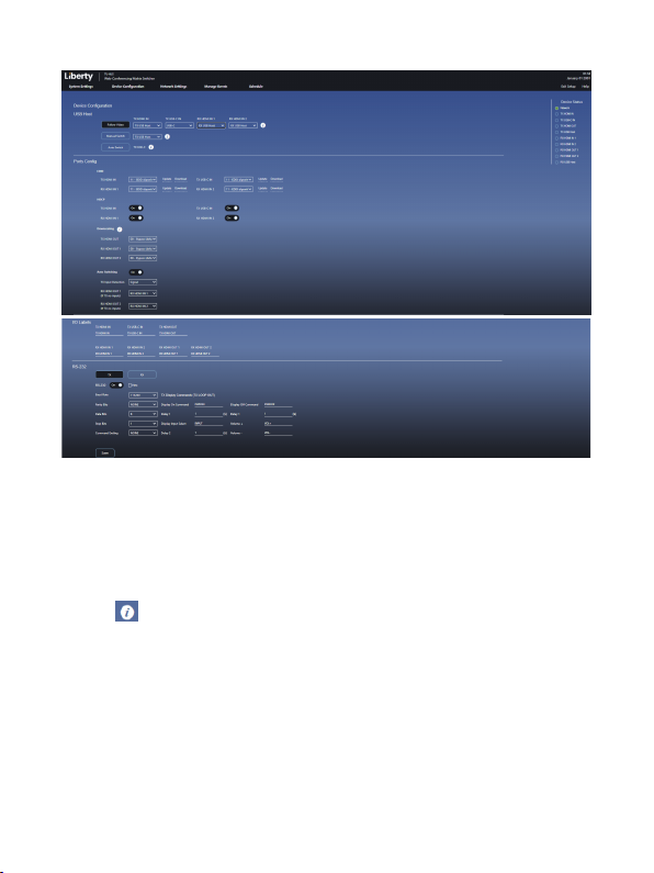
■ Device Configuration Page
USB Host
① Follow Video: You can set the Host port to follow video mode for each
input channel.
② Manual Switch: You can manually select the Host port.
③ Auto Switch: When “Auto Switch” is selected, the system will detect the
connection status of the Host port, and select the Host port automatically.
Note:
The icon is used for function annotation.
Ports Config
① EDID: You can set the EDID of each input channel.
② HDCP: You can turn on/off the HDCP of each input channel. *Note.. HDCP
protected content or devices will not pass when HDCP is turned off
③ Downscaling: You can set the output mode (Bypass/4K to 1080P/Auto) of
each output channel.
④ Auto Switching: You can turn on/off the auto switching function.
TX input Detection: Set the TX input to be signal detection or 5V detection.
14 / 25
Page 17
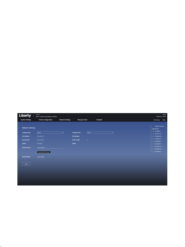
RX HDMI OUT1(if TX no inputs): Configure the signal source for RX OUT 1.
When there is no signal input for TX, RX OUT 1 will automatically output the
input signal from RX.
RX HDMI OUT2(if TX no inputs): Configure the signal source for RX OUT 2.
When there is no signal input for TX, RX OUT 2 will automatically output the
input signal from RX.
I/O Labels: You can change the input & output names which are displayed
on the operation interface.
RS-232 Serial Port Configuration: You can configure the TX's/RX's RS-232
serial port with Baud Rate, Parity Bits, Data Bits, Stop Bits and Command
Ending, power on/off TV, and increase/decrease the TV audio volume.
Note: When Hex option is selected, the string must be hexadecimal, otherwise
it cannot take effect. For example, HEX format: 11 22 33 44 55 66.
After setting up, click “Save” to take effect.
■ Network Settings Interface
① Network Settings:
or Manual. When it is set to DHCP, the IP address will be assigned by DHCP
server. When it is set to Manual, the IP address can be set manually.
② DHCP Client ID: You can renew DHCP lease.
③ Reset Network: You can reset the Network settings.
After setting up, click “Save” to take effect.
The IP mode of Network can be configured to DHCP
15 / 25
Page 18
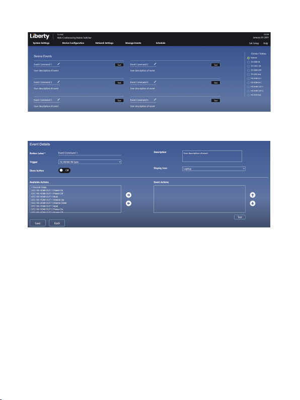
■ Manage Events Interface
Up to 6 events management are supported, and each event can be edited
separately, as shown in the figure below.
Event Details
① Button Label*: You can change the button label.
② Description: You can add description.
③ Trigger: Click the drop-down list to select the trigger method.
④ Show button: You can switch event d
operation interface, as shown in the following figure).
⑤ Display Icon: Click the drop-down list to select the display icon (displayed
on the operation interface, as shown in the following figure).
vailable Actions: Display all available action commands. You can move
⑥ A
the commands to the “Event Actions” box by clicking the right arrow.
⑦ Event Actions: Display the action commands to be executed. You can click
the up and down arrows to adjust the sequence of the commands, or click the
left arrow to delete the commands.
isplay button (displayed on the
16 / 25
Page 19
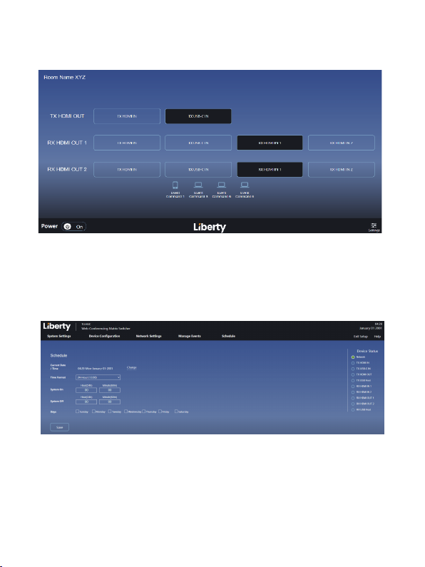
After setting action commands, click “TEST” to send commands.
After setting up, you can click “Save” to save the settings, or click “Back” to
go back to the previous level.
■ Schedule Interface
After turning off the function of “Set time automatically” on the System
Settings interface, you can set the system time in 12-hour or 24-hour hours
on this interface.
17 / 25
Page 20

API Commands
7.
The product also supports API commands for control. Connect the RS-232
port of the product to a PC with a 3-pin phoenix connector cable. Then, open
a Serial Command tool on PC to send ASCII commands to control the
product. The ASCII command list about the product is shown as below.
ASCII Commands
RS-232 Communication Protocol
Baud rate: 115200; Data bit: 8; Stop bit: 1; Parity bit: none.
The end mark of command is “<CR><LF>”.
TCP/IP Communication Protocol
Port: 8000
Command Code
Help
GetFirmwareVersion Get the firmware version
SetPower Param
GetPower Get the standby status
FactoryReset Factory Default
SetAV Param1 From
Param2
GetAV Param
Function Description
Get the list of all commands
Enter/exit standby mode
Param = ON, OFF
Set output switching
Param1 = LOOP, RXOUT1,
RXOUT2
Param2 = USBC, HDMI,
RXHDMI1, RXHDMI2,
AVMUTE, OFF
Get output switching status
Param = LOOP, RXOUT1,
RXOUT2
Command & Feedback Example
>Help
======================================
TU-HUC Help Info
FW Version: TX 1.0.0 RX 1.0.0 GUI 1.0.0
Help Get the list of all commands
GetFirmwareVersion Get the firmware version
......................
======================================
>GetFirmwareVersion
< TX 1.0.0 RX 1.0.0 GUI 1.0.0
>SetPower ON
<Power ON
>SetPower OFF
<Power OFF
>GetPower
<PON
<POFF
>FactoryReset
<Sure to RESET system and network to default
settings? Type "Yes" after next prompt to confirm…
>Yes
>SetAV LOOP From USBC
<AV LOOP From USBC
>SetAV RXOUT1 From AVMUTE
<AV RXOUT1 From AVMUTE
>GetAV RXOUT1
<USBC
18 / 25
Page 21

Command Code
SetTxLoopFollow
Hdbt Param
GetTxLoopFollow
Hdbt
SetTxAutoSwitchOn
Param
GetTxAutoSwitchOn
SetTxAutoSwitch
Mode Param
GetTxAutoSwitch
Mode
GetTxHdbtSource
SetDownScale
Param1 To Param2
GetDownScale
Param
SetTxAudioMute
Param
GetTxAudioMute
SetRxAudioMute
Param
GetRxAudioMute
Function Description
Set TX LOOP follow HDBT
source
Param = ON, OFF
Get TX LOOP follow HDBT
source
Enable/Disable TX
auto-switching mode
Param = ON, OFF
Get TX auto-switching mode
status
Set TX auto-switching mode
Param = 0: 5V detection
1: signal detection
Get TX auto-switching mode
status
Get TX HDBT source from
which input
Set downscaling mode
Param1 = LOOP, RXOUT1,
RXOUT2
Param2 =
AUTO: automatically
according to display's
capability
ON: force 4K to 1080p
OFF: bypass video
Get downscaling mode
Param = LOOP, RXOUT1,
RXOUT2
Enable/Disable TX
de-embedding audio mute
Param = ON, OFF
Get TX de-embedding audio
mute status
Enable/Disable RX
de-embedding audio mute
Param = ON, OFF
Get RX de-embedding audio
mute status
Command & Feedback Example
>SetTxLoopFollowHdbt ON
<TxLoopFollowHdbt ON
>GetTxLoopFollowHdbt
<ON
>SetTxAutoSwitchOn ON
<TxAutoSwitchOn ON
>GetTxAutoSwitchOn
<ON
>SetTxAutoSwitchMode 1
<TxAutoSwitchMode 1
>GetTxAutoSwitchMode
<1
>GetTxHdbtSource
<USBC
>SetDownScale RXOUT1 To AUTO
<DownScale RXOUT1 To AUTO
>GetDownScale RXOUT1
<AUTO
>SetTxAudioMute ON
<TxAudioMute ON
>GetTxAudioMute
<ON
>SetRxAudioMute ON
<RxAudioMute ON
>GetRxAudioMute
<ON
19 / 25
Page 22

Command Code
SetEDID Param1 To
Param2
GetEDID Param
SetHDCP Param1
To Param2
GetHDCP Param
Function Description
Set the EDID mode
Param1 = USBC, HDMI,
RXHDMI1, RXHDMI2
Param2 =
00 - 1920x1080@60 8bit
Stereo (default)
01 - WUXGA 1920x1200
02 - 1920x1080@60 8bit
High Definition Audio
03 - 3840x2160@60Hz 4:2:0
Deep Color Stereo Audio
04 - 3840x2160@60Hz
Deep Color Stereo Audio
05 - 3840x2160@30Hz
8bit Stereo Audio
06 - 3840x2160@60Hz
Deep Color High Definition
Audio
07 - 3840x2160@60Hz
Deep Color HDR LPCM 6CH
08 - copy EDID from TX
HDMI output
09 - copy EDID from RX
HDMI output 1
10 - copy EDID from RX
HDMI output 2
11 - EDID dipswitch
12 - User Defined
Get the EDID mode
Param = USBC, HDMI,
RXHDMI1, RXHDMI2
Set input port HDCP
ON/OFF
Param1 = USBC, HDMI,
RXHDMI1, RXHDMI2
Param2 = ON, OFF
Get input port HDCP
ON/OFF status
Param = USBC, HDMI,
RXHDMI1, RXHDMI2
Command & Feedback Example
>SetEDID HDMI To 01
<EDID HDMI To 01
>GetEDID HDMI
<01
>SetHDCP USBC To OFF
<USBC HDCP OFF
>GetHDCP USBC
<USBC HDCP OFF
20 / 25
Page 23

Command Code
SetUsbSwitchMode
Param
GetUsbSwitchMode
GetUsbSwitchStatus
SetUsbManual Param
GetUsbManual
SetUsbFollow
Param1 To Param2
GetUsbFollow Param
SetPortLabel Param1
To Param2
GetPortLabel Param
SetTimeSystem
Param
GetTimeSystem
Function Description
Set USB switch mode
Param =
AUTO: USB 5V detection
then switch
MANUAL: manual switch
FOLLOW: follow video
switch
Get USB switch mode
Get USB switch status
Set USB manual
Param = USB-C, TXHOST,
RXHOST
Get USB manual status
Set USB follow
Param1 = HDMI, RXHDMI1,
RXHDMI2
Param2 = TXHOST,
RXHOST
Get USB follow status
Param = HDMI, RXHDMI1,
RXHDMI2
Set port label
Param1 = USBC, HDMI,
LOOP, RXHDMI1,
RXHDMI2, RXOUT1,
RXOUT2
Param2 = xxxx
Get port label
Param = USBC, HDMI,
LOOP, RXHDMI1,
RXHDMI2, RXOUT1,
RXOUT2
Set time system is 12-hour
or 24-hour
Param = 12, 24
Get time system
Command & Feedback Example
>SetUsbSwitchMode AUTO
<UsbSwitchMode AUTO
>GetUsbSwitchMode
<AUTO
>GetUsbSwitchStatus
<USB-C
>SetUsbManual USB-C
<UsbManual USB-C
>GetUsbManual
<USB-C
>SetUsbFollow HDMI To TXHOST
<UsbFollow HDMI TXHOST
>GetUsbFollow HDMI
<TXHOST
>SetPortLabel USBC To AIRBOOK
<PortLabel USBC To AIRBOOK
>GetPortLabel USBC
<AIRBOOK
>SetTimeSystem 12
<TimeSystem 12
>GetTimeSystem
<TimeSystem 12
21 / 25
Page 24

Command Code
SetSchedule <Param
1,Param2,Param3,
Param4,Param5,
Param6,Param7,
Param8,Param9,
Param10, Param11>
GetSchedule Get Schedule time
SetTimeAutoOn
Param
GetTimeAutoOn
GetAutoTime
SetLocalTime <
Param1,Param2,
Param3,Param4,
Param5,Param6>
GetLocalTime Get current time
SetDaylightOn Param
GetDaylightOn
Function Description
Set Schedule time
Param1 = 0 ~ 23(hour)
(Param1= 8 or 8AM, 20 or
8PM)
Param2 = 0 ~ 59(min)
Param3 = 0 ~ 23(hour)
(Param3 = 8 or 8AM, 20 or
8PM)
Param4 = 0 ~ 59(min)
Param5 = 0 ~ 1(Sun)
Param6 = 0 ~ 1(Mon)
Param7 = 0 ~ 1(Tues)
Param8 = 0 ~ 1(Wed)
Param9 = 0 ~ 1(Turs)
Param10 = 0 ~ 1(Fri)
Param11 = 0 ~ 1(Sat)
Enable/Disable auto time
Param = ON, OFF
Get auto time status
Get auto time
Initialize the time setting
Param1 = 2001 ~ 2037(year)
Param2 = 1 ~ 12(month)
Param3 = 1 ~ 31(date)
Param4 = 0 ~ 23(hour)
(Param4 = 8 or 8AM, 20 or
8PM)
Param5 = 0 ~ 59(min)
Param6 = 0 ~ 59(sec)
Set Daylight on/off
Param = ON, OFF
Get Daylight on/off
Command & Feedback Example
>SetSchedule <8,0,10,0,0,1,1,1,1,1,1>
<Schedule <8,0,10,0,0,1,1,1,1,1,1>
>SetSchedule <8PM,0,13,0,0,1,1,1,1,1,1>
<Schedule <8PM,0,1PM,0,0,1,1,1,1,1,1>
>GetSchedule
<<8,0,10,0,0,1,1,1,1,1,1>
<<8AM,0,1PM,0,0,1,1,1,1,1,1>
>SetTimeAutoOn ON
<TimeAutoOn ON
>GetTimeAutoOn
<ON
>GetAutoTime
<Time <2020,1,1,1,1,1>
<Time <2023,5,6,4PM,19,56>
>SetLocalTime <2020,1,1,1,1,1>
<Time <2020,1,1,1,1,1>
>SetLocalTime <2020,1,1,1PM,1,1>
<Time <2020,1,1,1PM,1,1>
>GetLocalTime
<<2020,1,1,1,1,1>
<<2050,5,13,6AM,36,49>
>SetDaylightOn ON
<DaylightOn ON
>GetDaylightOn
<ON
22 / 25
Page 25

Command Code
SetDaylightTime
<Param1,Param2,
Param3,Param4,
Param5,Param6,
Param7,Param8,
Param9,Param10,
Param11,Param12>
GetDaylightTime
GetIPv4Address
SetIPv4 <XXX.XXX.
XXX.XXX>
<YYY.YYY.YYY.YYY>
<ZZZ.ZZZ.ZZZ.ZZZ>
SetCecSrcMenu
SetCecSrcUp
SetCecSrcDown
SetCecSrcLeft
SetCecSrcRight
SetCecSrcBack
SetCecSrcEnter
SetCecSrcOn
Function Description
Set Daylight Time
Param1 = 1 ~ 12(start month)
Param2 = 1 ~ 6(start week)
Param3 = 0 ~ 6(start day)
Param4 = 0 ~ 23(start hour)
(Param4=8 or 8AM, 20 or
8PM)
Param5 = 0 ~ 59(start min)
Param6 = 1 ~ 12(end month)
Param7 = 1 ~ 6(end week)
Param8 = 0 ~ 6(end day)
Param9 = 0 ~ 24(end hour)
(Param9=8 or 8AM, 20 or
8PM)
Param10 = 0 ~ 59(end min)
Param11 = 0 ~ 23(adjust hour)
Param12 = 0 ~ 59(adjust min)
Get Daylight time
Get the IP to access GUI
Set the GUI IP address
XXX = 0 ~ 255(IP ADDRESS)
YYY = 0 ~ 255(MASK)
ZZZ = 0 ~ 255(GATE)
Send CEC MENU command
to TX HDMI source device
Send CEC UP command to
TX HDMI source device
Send CEC DOWN
command to TX HDMI
source device
Send CEC LEFT command
to TX HDMI source device
Send CEC RIGHT command
to TX HDMI source device
Send CEC BACK command
to TX HDMI source device
Send CEC ENTER
command to TX HDMI
source device
Send CEC ON command to
TX HDMI source device
Command & Feedback Example
>SetDaylightTime <8,1,1,10,0,12,1,1,10,0,1,0>
<DaylightTime <8,1,1,10,0,12,1,1,10,0,1,0>
>SetDaylightTime <1,2,0,1PM,0,1,2,0,14,0,0,0>
<DaylightTime <1,2,0,1PM,0,1,2,0,2PM,0,0,0>
>GetDaylightTime
<<8,1,1,10,0,12,1,1,10,0,1,0>
<<1,2,0,1PM,0,1,2,0,2PM,0,0,0>
>GetIPv4Address
<192.168.0.178
>SetIPv4 <192.168.0.178> <255.255.255.0>
<192.168.0.1>
<IP <192.168.0.178> <255.255.255.0>
<192.168.0.1>
>SetCecSrcMenu
<CecSrcMenu
>SetCecSrcUp
<CecSrcUp
>SetCecSrcDown
<CecSrcDown
>SetCecSrcLeft
<CecSrcLeft
>SetCecSrcRight
<CecSrcRight
>SetCecSrcBack
<CecSrcBack
>SetCecSrcEnter
<CecSrcEnter
>SetCecSrcOn
<CecSrcOn
23 / 25
Page 26

Command Code
SetCecSrcOff
SetCecSrcStop
SetCecSrcPlay
SetCecSrcPause
SetCecSrcPrev
SetCecSrcNext
SetCecSrcRewind
SetCecSrcFast
Forward
SetCecDisplayOn
Param
SetCecDisplayOff
Param
SetCecDisplaySource
Param
SetCecDisplayMute
Param
SetCecDisplayVol
Plus Param
SetCecDisplayVol
Minus Param
Function Description
Send CEC OFF command to
TX HDMI source device
Send CEC STOP command
to TX HDMI source device
Send CEC PLAY command
to TX HDMI source device
Send CEC PAUSE command
to TX HDMI source device
Send CEC PREV command
to TX HDMI source device
Send CEC NEXT command
to TX HDMI source device
Send CEC rewind command
to TX HDMI source device
Send CEC fast-forward
command to TX HDMI
source device
Send CEC ON command to
display
Param = LOOP, RXOUT1,
RXOUT2
Send CEC OFF command
to display
Param = LOOP, RXOUT1,
RXOUT2
Send CEC SOURCE
command to display
Param = LOOP, RXOUT1,
RXOUT2
Send CEC MUTE command
to display
Param = LOOP, RXOUT1,
RXOUT2
Send CEC volume plus
command to display
Param = LOOP, RXOUT1,
RXOUT2
Send CEC volume minus
command to display
Param = LOOP, RXOUT1,
RXOUT2
Command & Feedback Example
>SetCecSrcOff
<CecSrcOff
>SetCecSrcStop
<CecSrcStop
>SetCecSrcPlay
<CecSrcPlay
>SetCecSrcPause
<CecSrcPause
>SetCecSrcPrev
<CecSrcPrev
>SetCecSrcNext
<CecSrcNext
>SetCecSrcRewind
<CecSrcRewind
>SetCecSrcFastForward
<CecSrcFastForward
>SetCecDisplayOn LOOP
<CecDisplayOn LOOP
>SetCecDisplayOff LOOP
<CecDisplayOff LOOP
>SetCecDisplaySource LOOP
<CecDisplaySource LOOP
>SetCecDisplayMute LOOP
<CecDisplayMute LOOP
>SetCecDisplayVolPlus LOOP
<CecDisplayVolPlus LOOP
>SetCecDisplayVolMinus LOOP
<CecDisplayVolMinus LOOP
24 / 25
Page 27
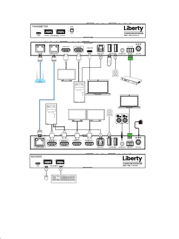
8. Application Example
LAN
LAN
TP-LINK
Router
CAT 6A/7 cable
Local Computer
LAN
Mouse
TV 1
Local
Computer
Keyboard
Laptop
TV 2 TV 3
25 / 25
USB
Camera
USB
Camera
HDMI Matrix with
RS-232 function
Speakers
PC2
Power Supply
 Loading...