

Page 1
USER MANUAL
IPEX-USB2-H/-C Owners Manual
DigiIP Series USB 2.0 High Speed over IP.
Fully routable USB over IP with Isochronous data Support
www.libav.com 800.530.8998
Page 2

PRODUCT OVERVIEW
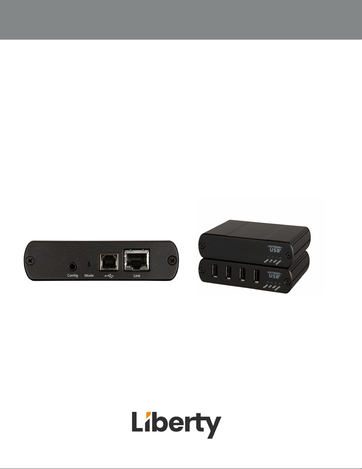
The DigiIP IPEX-USB2 allows users to extend USB beyond the standard 5m cable limit for USB 2.0 devices.
The IPEX-USB2 is composed of 2 units the IPEX-USB2-C is for USB devices and the IPEX-USB2-H is for host
devices. No software drivers are needed for the IPEX-USB2 units. IPEX-USB2-H does not need power as it
receives power from the host. Seven USB devices can be routed to a single host.
PACKAGE CONTENTS
• IPEX-USB2-H
• (1) USB 2.0 cable)
• IPEX-USB2-C
• 24V 1A Power Adapter with US, UK, AU AND EU Power Adapters
Rev 222312
OWNERS MANUAL IPEX-USB2
Page 3
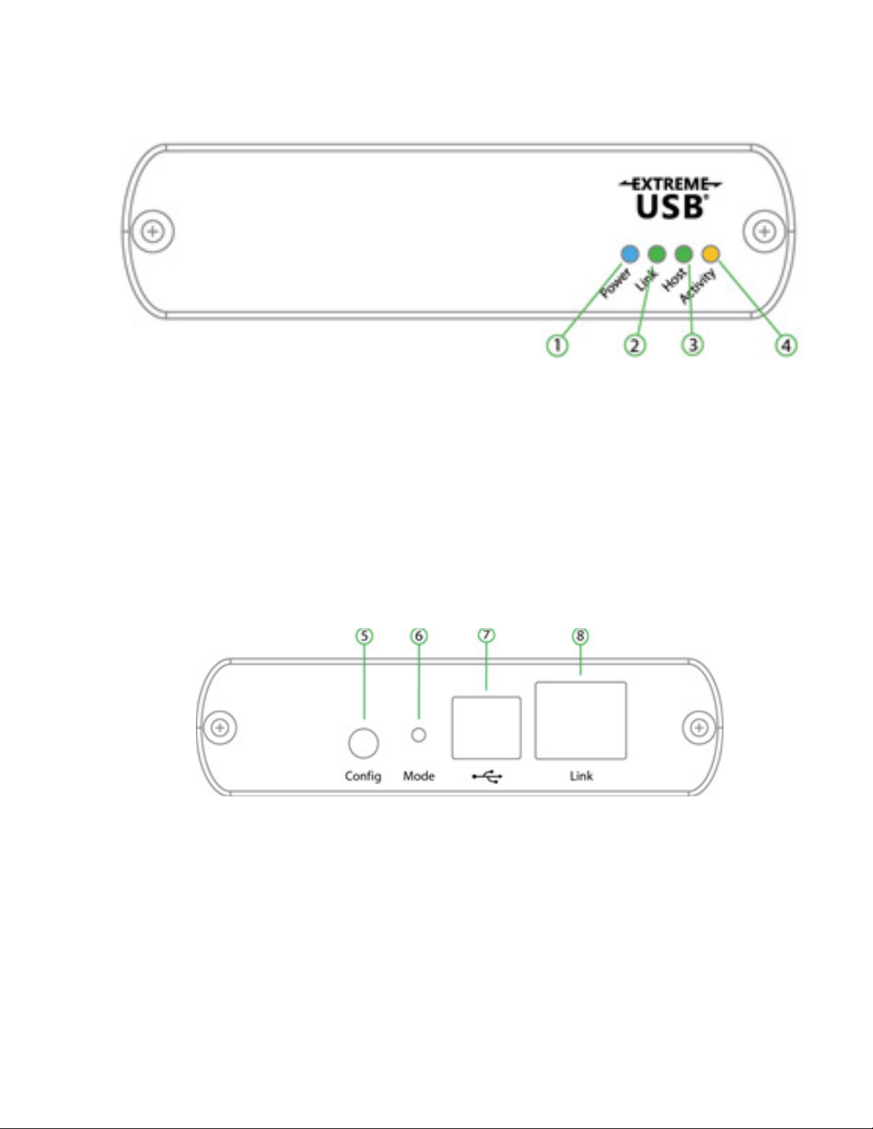
IPEX-USB2-H PRODUCT BREAKDOWN
1. Power LED (Blue) :When the blue power LED is on the IPEX-USB2-H has power. When the
LED is o no power is supplied by the host computer.
2. Link LED (Green) : LED is on when link between host and client is established. LED is o
when no link is made between host and client. Slow blinking is when the unit is trying to establish a link. Fast blinking the unit is in pairing mode..
3. Host LED(Green) :When the green LED is on the unit is properly enumerated on the host
computer. The LED blinks when the unit is in a suspended state.
4. Activity LED (Amber) : Flashing light means data is transmitting between the client and host
devices.
5. Cong: for future use / rmware
6. Mode: Press to enter pairing mode.
7. USB Host Port: Connect USB cable to host computer
8. Ethernet port: Connect to Client device or network switch
OWNERS MANUAL IPEX-USB2
3
Page 4
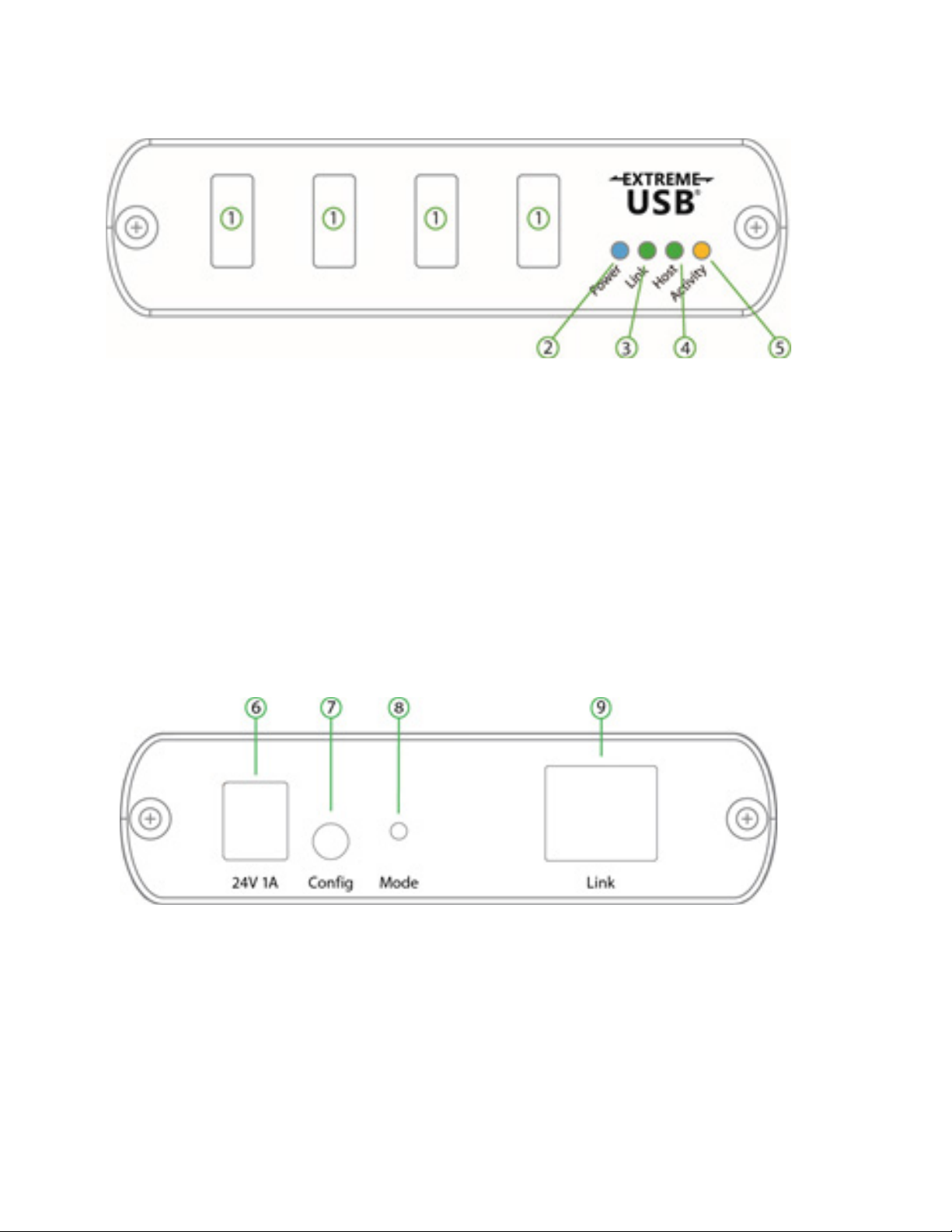
IPEX-USB2-C PRODUCT BREAKDOWN
1. USB Device Ports: Accepts Type A connections to UB devices.
2. Power LED (Blue) :When the blue power LED is on the IPEX-USB2-H has power. When the
LED is o no power is supplied by the host computer.
3. Link LED (Green) : LED is on when link between host and client is established. LED is o
when no link is made between host and client. Slow blinking is when the unit is trying to establish a link. Fast blinking the unit is in pairing mode..
4. Host LED(Green) :When the green LED is on the unit is properly enumerated on the host
computer. The LED blinks when the unit is in a suspended state.
5. Activity LED (Amber) : Flashing light means data is transmitting between the client and host
devices.
6. Power In : Connects to power adapter.
7. Cong: for future use / rmware
8. Mode: Press to enter pairing mode.
9. Ethernet port: Connect to Host device or network switch
Rev 222312
OWNERS MANUAL IPEX-USB2
Page 5

PAIRING HOST AND CLIENT
1. Ensure the Host and Client units are connected directly to each other, or connected to the
same subnet on the network switch
.
2. Press and hold the Mode button on the back of the Host unit. Release the button within 10
seconds. The Link LED will start to blink and this indicates the unit is in Pairing mode.
3. Within 10 minutes of activating the pairing mode on the Host unit. Press and hold the
Mode button on the back of the Client unit. Release within 10 seconds to place the Client into
pairing mode. The Link LED will start to blink.
4.The Link LED on both Host and Client will start to blink slowly and then stay on. Once the
Link LED is solid on the units are linked together.
ROUTING HOST AND CLIENT
Routing of the Host and Client dynamically will be done through Arranger. Please pull up the
Arranger Manual of the series you are using for details on how to route Host and Client.
OWNERS MANUAL IPEX-USB2
5
Page 6

TECHNICAL SPECIFICATIONS
Model IPEX-USB2
Physical Parameter
Case Material Client: Industrial-grade metal chassis with metal brackets
Host: Industrial-grade metal chassis with metal brackets
Dimensions Host: 100mm [W] x 76mm [D] x 26mm [H]
Client: 100mm [W] x 76mm [D] x 26mm [H]
Weight Host: 181g
Receiver: 181g
Power Protecon ESD protecon with human body model — ±8kV (Air-gap discharge) & ±4kV
(Contact discharge)
Power Output DC 24V 1A
Power Input AC 100-240V 50/69Hz
USB Power 600mA each port concurrently; 1A per port if 2 of less ports are used
Operang Temperature 32 - 122°F / 0 - 50°C
USB Specicaons
USB 2.0
Bandwidth 480Mbps
Trac Types All USB 2.0 Trac Types
Device Types All USB 2.0 Device Types
Networking
Standards 1000Base-T
Data Trac Layer 2
Connecvity
Inputs Host: 1x USB Type B
1x RJ45
Client: 4x USB Type A
1x RJ45
1x DC 24V
Transmission
Max Distance switch to
device
Max Distance device to
device
328 / 100m over CAT5e/6/6a/7
328 / 100m over CAT5e/6/6a/7
Rev 222312
OWNERS MANUAL IPEX-USB2
Page 7

Thank you for your purchase.
For technical support please call our
toll-free number at 800-530-8998
or email us at [email protected]
OWNERS MANUAL IPEX-USB2
www.libav.com 800-530-8998
7
 Loading...