

Page 1
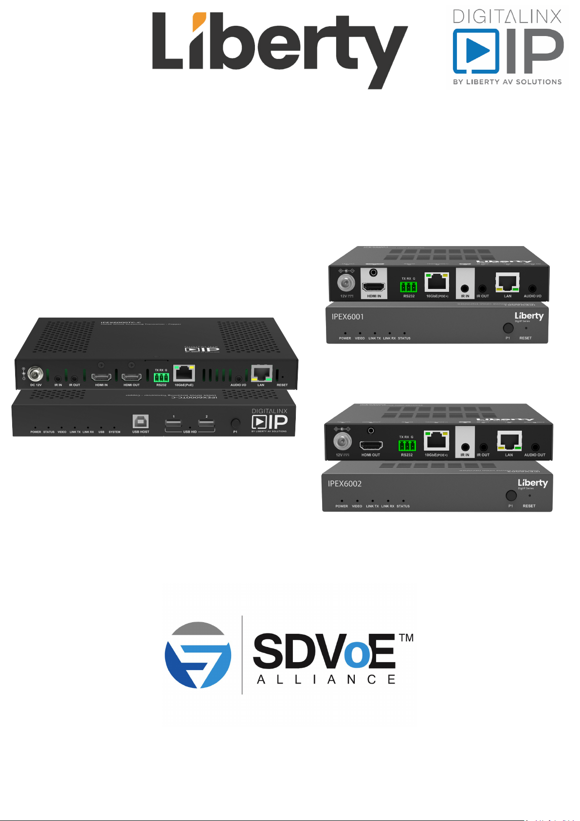
IPEX6000TC-C, IPEX6001, & IPEX6002 Install Guide,
Device Manual, and Specifications
Rev 200311
11675 Ridgeline Dr.
Colorado Springs, CO 80921
Toll-Free: 800-530-8998
Fax: 719-260-0075
Page 2

IPEX6000TC-C Install Guide
Product Features
IPEX6000TC-C Transceiver
The IPEX6000TC-C is an AVoIP PoE powered A/V transceiver integrated with both encoder and decoder conguraon
which can transmit and receive video signals simultaneously. The DigitalinxIP IPEX6000TC-C supports IP-based
switching and extension of true 4K/60Hz (4:4:4) video with zero frame latency up to 100 meters when using CAT6A
F/UTP cabling. The transceiver supports independent roung of all AV, USB HID, IR, Ethernet and RS232 signals. All
transceivers on an AV network can simultaneously transmit and receive full 4K 60 4:4:4 signals. The IPEX6000TC-C
is HDMI 2.0 and HDCP 2.2 compliant and supports all video resoluons that t into the HDMI 2.0 ming envelope
of 594 MHz, such as 4K@60Hz 4:4:4 24bpp and 4K@60Hz 4:2:0 30bpp HDR, including DolbyVision, HDR10 and
HLG. The transceiver features lite compression technology which is acvated automacally when the raw data
rate exceeds the Ethernet bandwidth so that all supported ming formats can be delivered through a single 10G
Ethernet cable.
The IPEX6000TC-C can be used in a point to point installaon or in a matrix conguraon that supports roung of
one to one and one to many including mul-view for single display outputs and video wall conguraons up to
an 8x5 (Rows x Columns).
When mulple IPEX6000TC-C transceivers are deployed on an AV network, for basic system access and operaon,
a license code from Liberty’s Arranger oering is required.
Port speed requirements for each transceiver is ~6-8Gbps for 4K signals and 3.2Gbps for 1080P signals, therefore
the IPEX6000TC-C requires a 10GbE PoE managed network switch for opmal performance.
Note: 1GbE managed network switches are not supported.
Package Contents
1. Installaon Guide
2. DC 12V 2A Power Supply with US, UK, EU, and AU adapters
3. 3-pin Removable Phoenix Screw Terminal
4. Mounng Ears (2 ea)
5. IR Emier
6. IR Receiver
3
Page 3

Product Features
IPEX6001 / 6002 Encoder / Decoder
IPEX6001 / 6002 encoders and decoders provide the economical, flexible and powerful solution at resolutions up
to 4096x2160@60Hz, 3840x2160@60Hz (4:4:4) and 3840x2160@60Hz (4:2:0 10-bit HDR). They allow
uncompressed UHD media to be switched and distributed over standard 10GbE Ethernet networks with zero
frame latency.
Flexible and Cost-effective Deployment
IPEX6001/6002 series products can work together with full-feature 6000 Series DigiIP products including
IPEX6000TC transceivers and 6000 series wall plate encoder / decoder in AV distribution / signal routing
applications. IPEX6001/6002 do not include video processing or scaling keeping cost down for applications where
these features are unnecessary. IPEX6002 cannot be used within a video wall (IPEX6001 can feed a video wall
with appropriate decoders), and IPEX6001 and 6002 can not be part of a multi-view application.
Multiple Signal Delivery
Standard features like bi-directional serial, bi-directional IR, Gigabit Ethernet, and independent analog audio
input/output are included. They are the perfect solution for any zero-frame latency and signal routing
applications. Common applications include classrooms, digital signage, conference rooms, performing arts and
broadcasts.
Port speed requirements for each encoder/decoder is ~6-8Gbps for 4K signals and 3.2Gbps for 1080P signals,
therefore the IPEX6001/6002 requires a 10GbE PoE managed network switch for optimal performance.
Note: 1GbE managed network switches are not supported.
Package Contents
1. Installation Guide
2. DC 12V 2A Power Supply with US, UK, EU, and AU adapters
3. 3-pin Removable Phoenix Screw Terminal
4. Mounting Ears (2 ea)
5. IR Emitter or Receiver
Page 4

IPEX6000TC-C Install Guide
IPEX6000TC-C Front Panel
Front and Rear Panels
1 2 3 4
1. Status / Diagnosc LEDs
• POWER:
• ON; device is on
• OFF; device is o
• STATUS:
• ON; device has entered HDMI cong mode
• BLINKING; The device is working in default mode
• OFF; the HDMI output has been congured as a LOOP output
• VIDEO
• ON; video signal is stable
• OFF; no video signal detected
• LINK TX
• BLINKING; device is connected to switch and or another device
• OFF; device is not connected to switch or another device
• LINK RX
• BLINKING; device is connected to switch and or another device
• OFF; device is not connected to switch or another device
• USB
• ON; the device is powered on
• BLINKING; This device is linked to another device, and its USB Host port is connected to a USB
host device.
• SYSTEM - for future use
2. USB B Host Connecon
3. USB HID Device Client Connecon
4. HDMI cong mode (Transceiver mode only)
• Press and hold 5 seconds to enter HDMI cong mode
• Press this buon once: when HDMI ports are in normal state, press this buon once to switch
the HDMI ports to support local loop out mode; when HDMI ports are in local loop out state,
press this buon once to switch the HDMI ports to original normal state i.e. Input, Output
4
Page 5

IPEX6000TC-C Rear Panel
IPEX6000TC-C Install Guide
1 2 3 4 5
1. 12V DC power input
2. IR receiver input
3. IR emier output
4. HDMI input
5. HDMI output
6. RS232 / serial connecon
7. 10GBaseT AV Network connecon with PoE support
8. Analog audio input/output
9. 10/100/1000BaseT LAN connecon
10. Factory RESET buon
• To set factory default, power the device down. While unit is powered down, press and hold the
RESET buon and power on the device. Hold the RESET buon for 20 seconds and then release
the RESET buon. The unit will be reset to Factory defaults aer you release the RESET buon.
6 7
8
9 10
5
Page 6
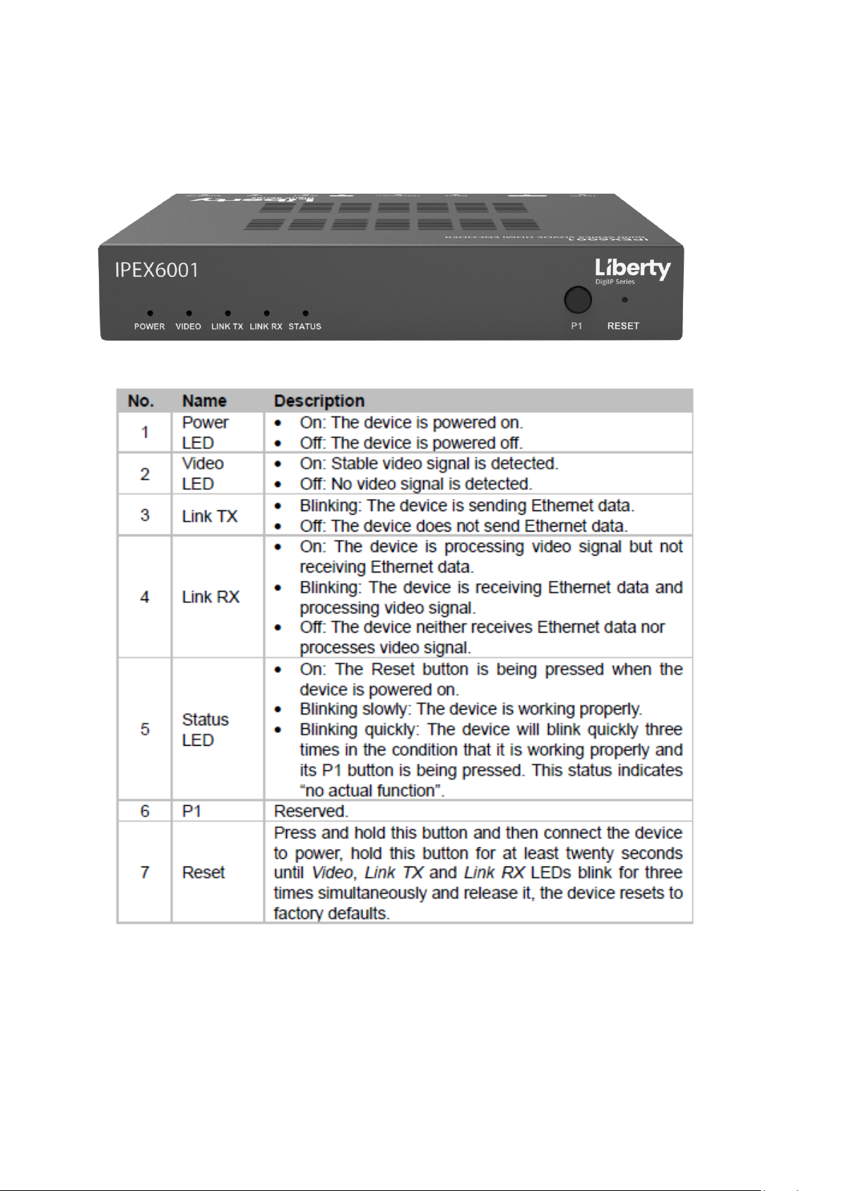
IPEX6001 Front Panel
Front and Rear Panels
Page 7
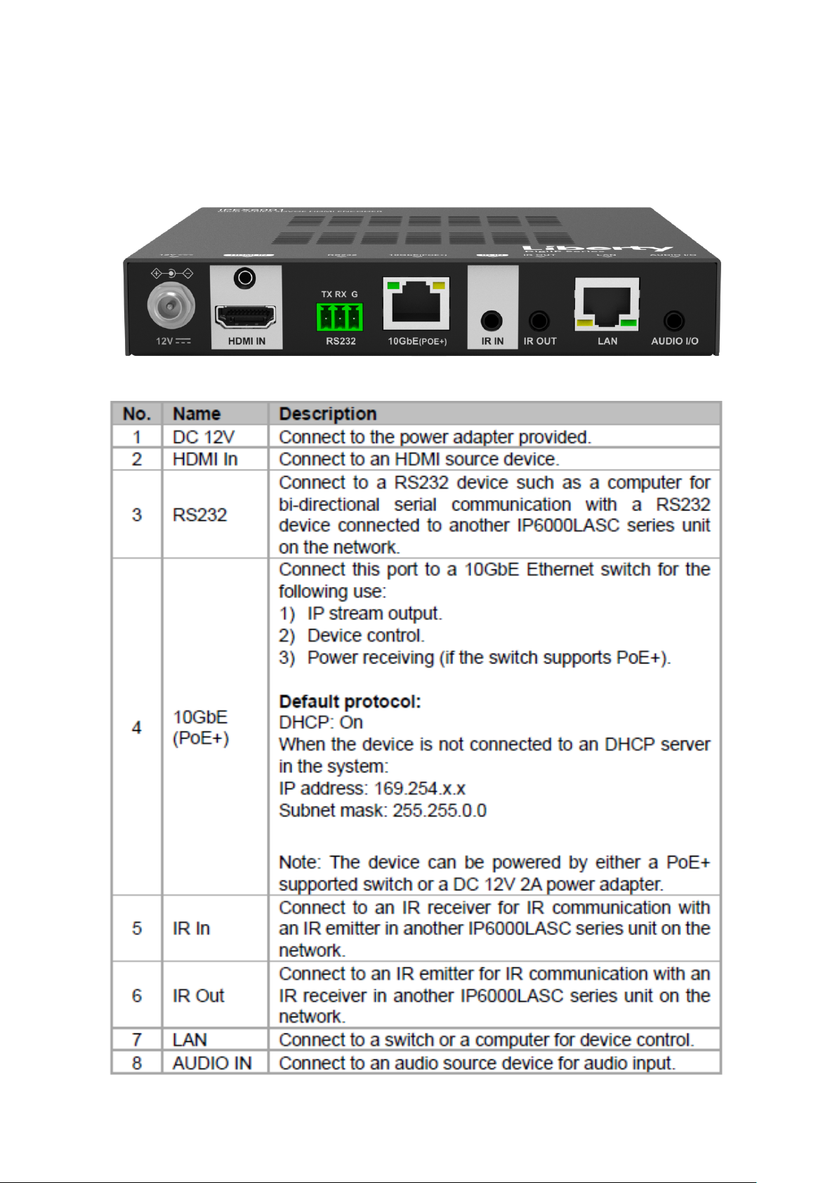
IPEX6001 Rear Panel
Front and Rear Panels
Page 8
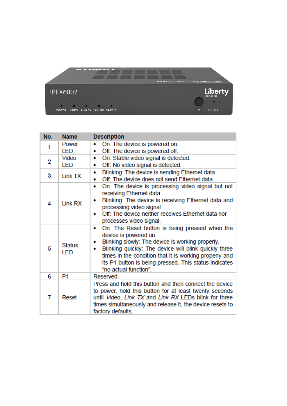
IPEX6002 Front Panel
Front and Rear Panels
Page 9
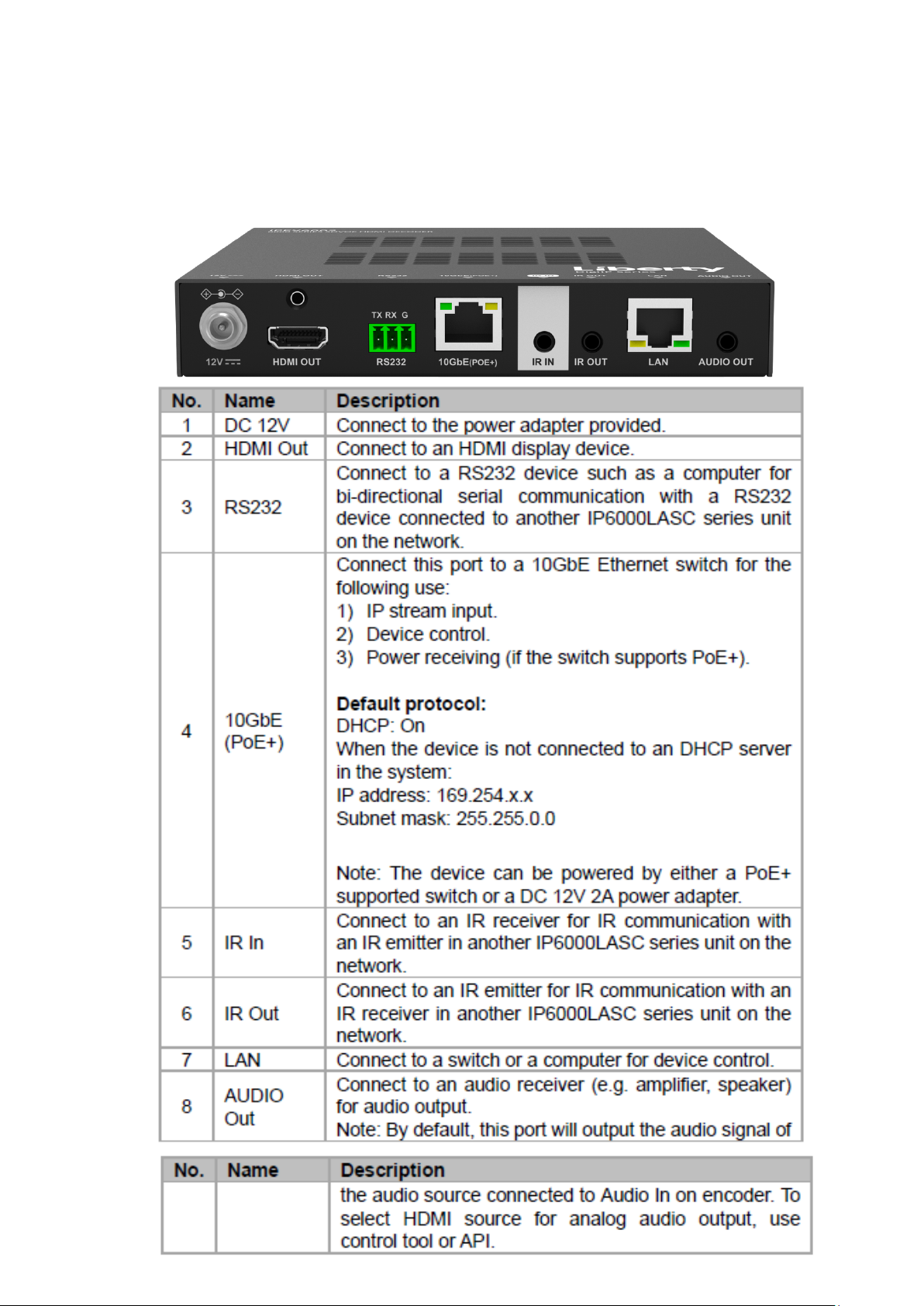
IPEX6002 Rear Panel
Front and Rear Panels
Page 10

IPEX6000TC-C Install Guide
Connect Transceivers / Encoders / Decoders to Network Switch
Configure a 10GbE managed PoE network switch for multicast video operation.
Note: A 1G network switch cannot be used with the 6000 series due to the high port speed requirements of the
IPEX6000TC-C, a 10GbE managed network switch is required.
Liberty has documented several network switch sengs for many common switch manufacturers, see
documents related to this product on the product page of the Liberty AV website (www.libav.com).
Connect Category 6A from the network switch to the appropriate transceivers 10GbE LAN port.
Use TIA/EIA-568B crimp paern for Category cable terminaon.
System Installation Instructions
1 8
Pin 1
Pin 2
Pin 3
Pin 4
Pin 5
Pin 6
Pin 7
Pin 8
TIA/EIA-568B
Orange/White
Green/White
Blue/White
Brown/White
Orange
Blue
Green
Brown
If the managed PoE network switch cannot provide adequate power to the transceiver, connect the included power
supply to the DC power input of the device and connect to a local AC power source.
Best Pracce
When installing the AV endpoints, create a spreadsheet of all AVoIP transceivers notang the MAC address, the
aached source/sync and the desired transceiver funcon, i.e. encoder, decoder or both. This will aid in fast
nal system commissioning that could be done remotely by accessing the AV system server via VPN or via port
forwarding. See Arranger Documentaon for more informaon on how to access the server and set up port
forwarding.
Device IP Sengs
The 6000 series devices default to DHCP so a router or DHCP server can assign an IP address to the device
automacally. If there is no router or DHCP server present it will default to APIPA i.e. 169.254/16 Network ID. You
will use the Arranger applicaon to nd and manage 6000 devices on a Network. See Device / System Control.
6
Page 11
IPEX6000TC-C Install Guide
Connecng HDMI Devices
Use only high quality High Speed HDMI cables rated for 18Gbps, do not exceed HDMI cable lengths over 5m/15’ for
transceiver HDMI connecons to AV sources and displays.
Connecng Audio Devices
The 3.5mm analog audio I/O connecon can be congured as an input or an output and is congured in the
Arranger server. Connect a 3.5mm stereo audio cable to the transceivers audio I/O port
Note: Audio output is 2 channel stereo audio only and is not capable of downmixing mul channel audio
Connecng USB Devices
A transceiver can be congured as either a USB host or client, this is congured in the Arranger server. Connect USB
components to transceivers with USB 2.0 rated cables, do not exceed cable lengths over 5m/15’
Note: 6000 Series supports USB HID, which is ideal for simple KVM or touch control. Do not use high quality USB
microphones or webcams on this transceiver
Connecng IR Components
The IR connecons on the transceivers provide a means to control remote IR equipment.
Note: Please ensure power is disconnected from the encoders and decoders before connecng the IR receiver to
the IR input ports on the devices.
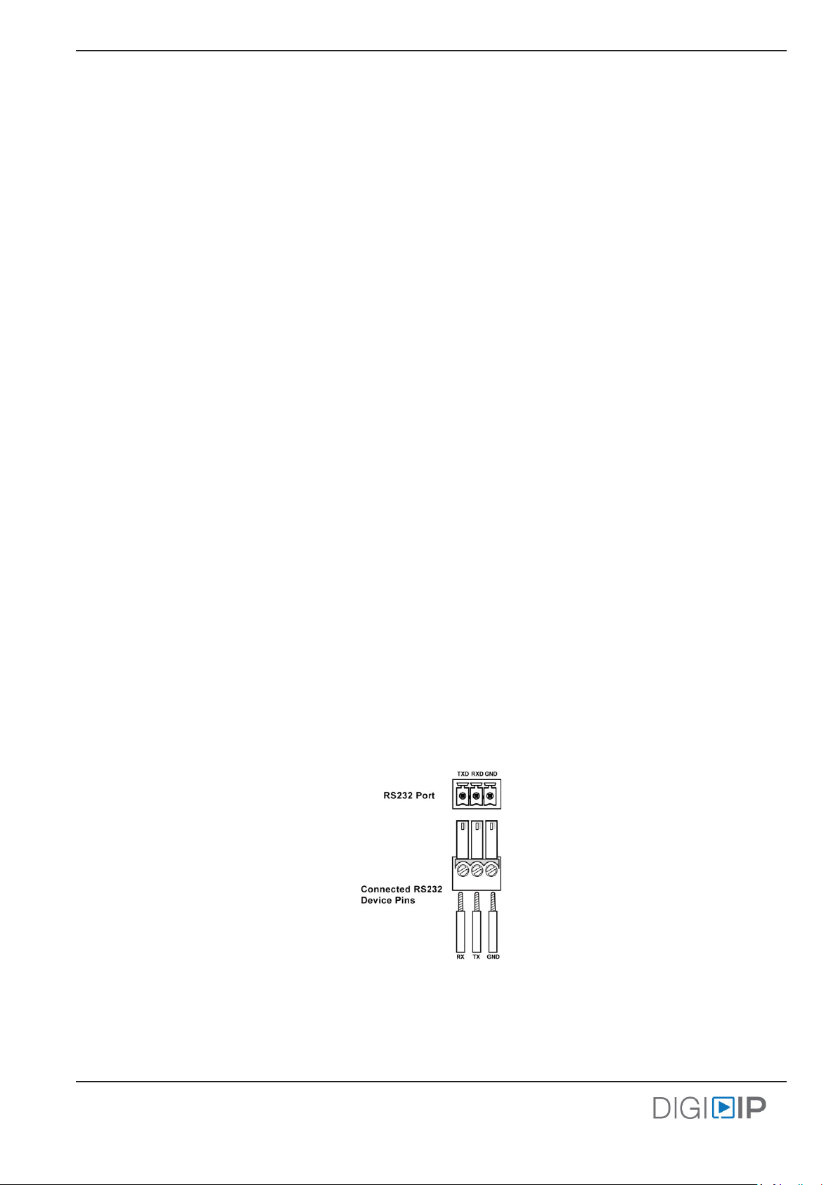
Connecng Serial / RS232 Compable Devices
The RS232 connecons on the transceivers provide a means to control 3rd party devices using serial commands.
Connect the TX, RX, and ground control signal wires to the removable 3-pole terminal block, be sure the wiring
from transceiver to the device is TX - RX, RX - TX, G - G. See illustraon below
7
Page 12

IPEX6000TC-C Install Guide
Device / System Control
Arranger is an AVoIP server applicaon that will congure and manage the 6000 series on an AV IP Network.
Arranger is licensed per endpoint for one AV Network and a license unlock code should have been provided upon
purchase of the Arranger DigiIP 6000 series license.
If you are missing the license unlock code contact [email protected] and have serial number of the hardware
controller nearby to conrm system license
Connect Arranger Controller
The provided Arranger hardware controller with the DigitalinxIP system should be hardwired via Ethernet to the
AV network switch.
Arranger Server Login
Once the hardware controller has been connected to the AV Network, the Arranger server applicaon can be
accessed via web browser on any PC that is connected to the same AV Network switch. By default the IP address
for the Arranger server is 169.254.1.1. For inial system setup your PC will need to be in the same Network ID, i.e.
169.254/16.
Upon rst login of the Arranger server you will be asked for an unlock code for your license, once the license has
been entered you will be prompted for login credenals, by default the user name is admin and the password is
admin to login to the system initially.
Once logged in you will be asked to change the admin login password.
Best Pracce
Log the changed password that you created in your project documentation spreadsheet.
Once logged in you can congure, manage and control all signal types for the DigitalinxIP 6000 series devices. A
complete operaon manual and API for the Arranger system is located in the Arranger server applicaon.
8
Page 13
IPEX6000TC-C Install Guide
Application Diagrams
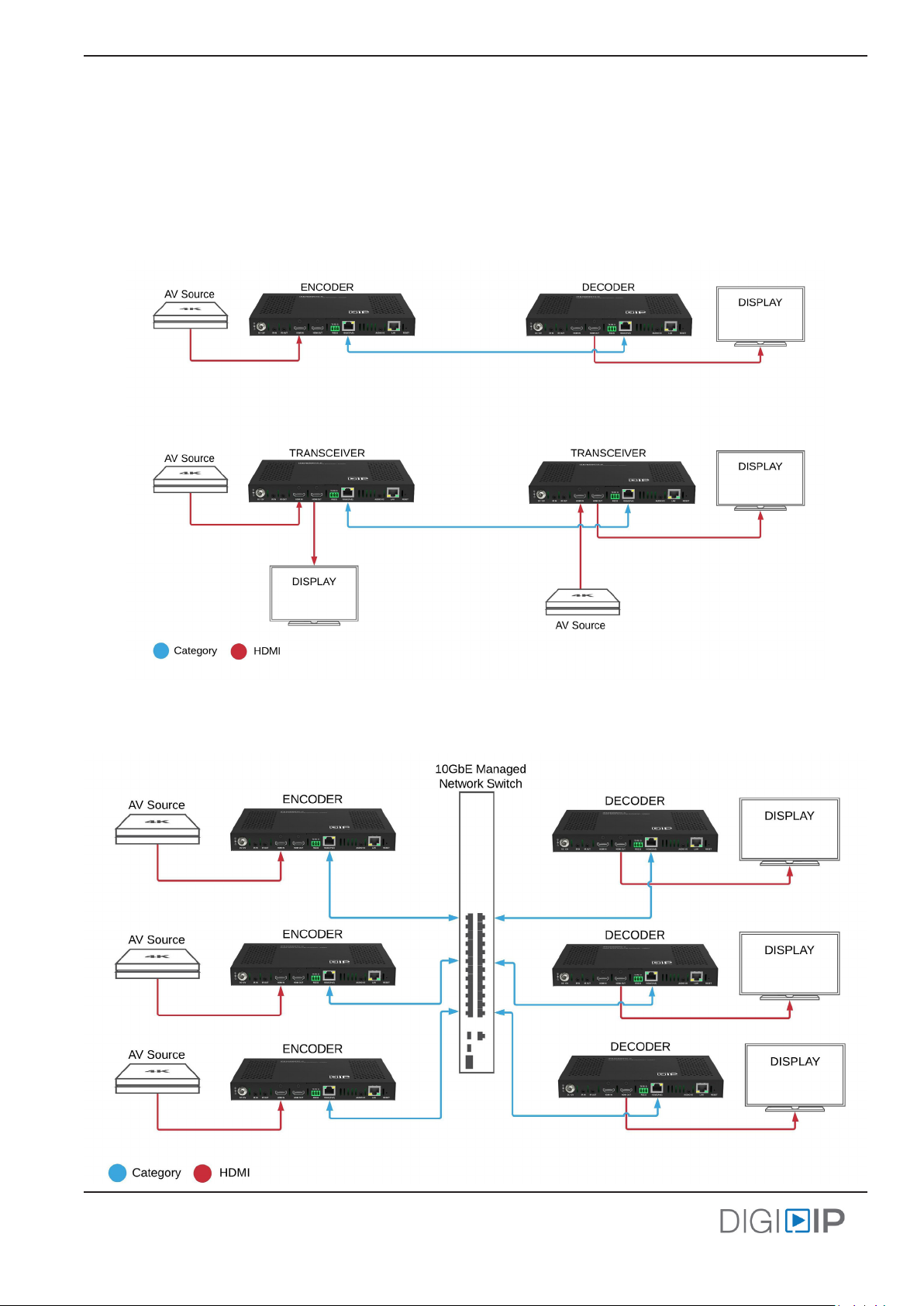
Note: Transceiver modes as notated (encoder, decoder or both) can be congured by the Arranger server
Point to Point AV Extender
Note: Both transceivers must be connected to local power AC outlet with the supplied DC power supplies, the
point to point applicaon does not support PoE.
A/V Network Matrix
9
Page 14
IPEX6000TC-C Install Guide
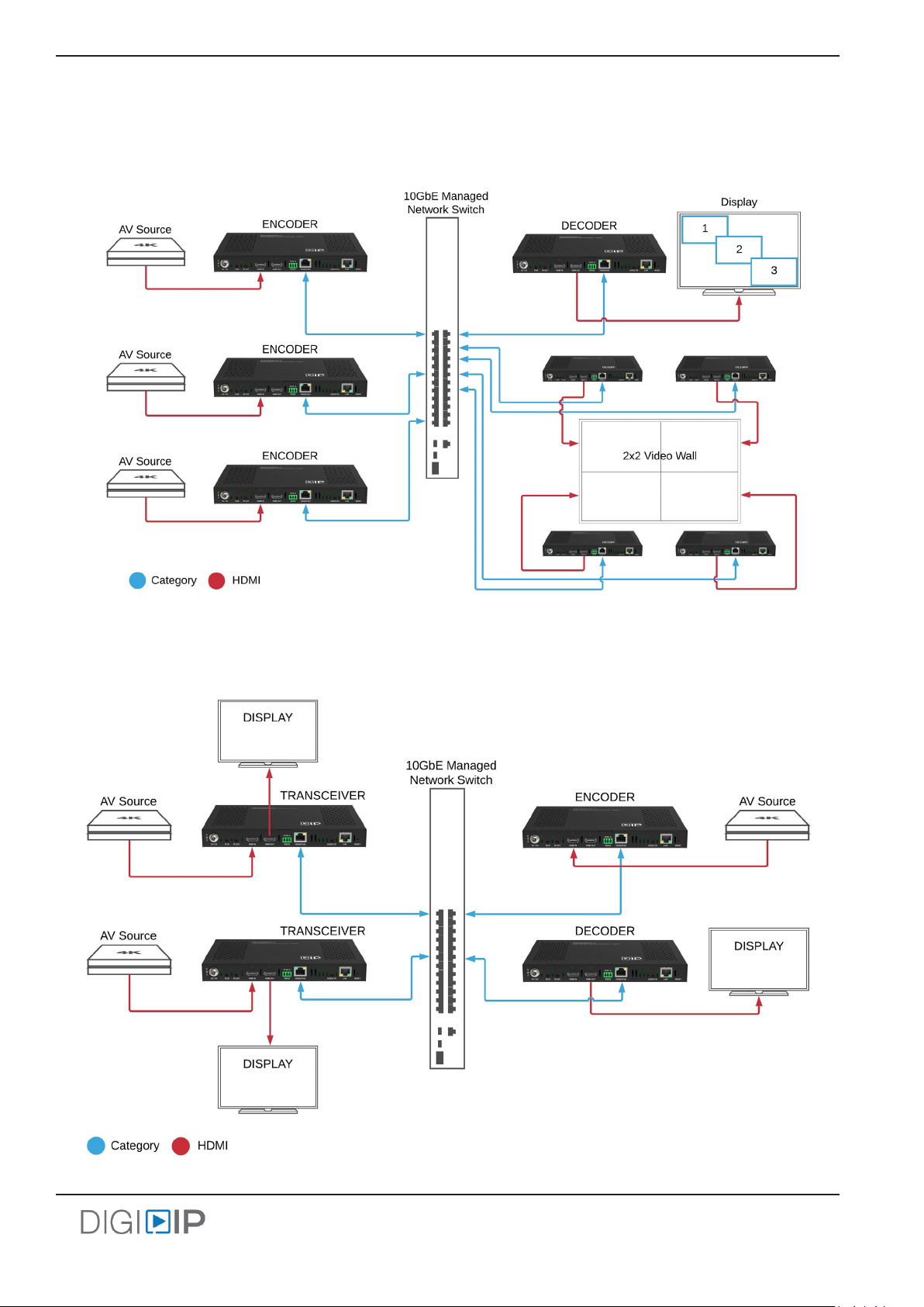
A/V Network Mul-view and Video Wall
A/V Network Transceiver Mode
10
Page 15

IPEX6000TC-C Technical Specifications
Input/Output Connecons
HDMI Input One (1) HDMI Type A Receptacle
HDMI Output One (1) HDMI Type A Receptacle
LAN 10GbE: One (1) 8P8C port (Shielded RJ45)
Power One (1) 5.5 mm OD, 2.1 mm ID Threaded Barrel
RS232 Port One (1) 3-pin Removable Terminal Block Connector
USB Device / Client Two (2) USB Type A Port
USB Host One (1) USB Type B Port
Audio Input / Output One (1) 3.5 mm TRS Receptacle
IR Input One (1) 3.5 mm TRS Receptacle
IR Output One (1) 3.5 mm TS Receptacle
Supported Audio, Video and Control
Video Input Resoluons Resoluons up to 4K@60Hz, 4:4:4
Video Output Resoluons Resoluons up to 4K@60Hz, 4:4:4
Video Compliance HDMI 2.0 and HDCP 2.2
Embedded Audio HDMI: LPCM, 2.0/5.1/7.1 channel, 44.1/48/96/192 kHz, Dolby True HD, up to 7.1,192kHz, DTS-
Supported Baud Rates 300, 600, 1200, 2400, 4800, 9600, 19200, 38400, 57600, 115200
USB Compliance USB 1.1 Full Speed up to 12Mbps
Video Wall Scale Capability Up to 8x5
Streaming Signal Characteriscs
Maximum Distance (point to point) 30m (90’) when using CAT6
Maximum Distance (matrix, mul-view, video wall) 30m (90’) when using CAT6
Cable Requirements Category 6 or greater with TIA/EIA-568B crimp paern
Encoding Data Rate 4K Signals: Up to 8Gbps
End to End Latency Zero Frame Latency
Chassis and Environmental
Dimensions (H x W x D) 25 mm x 215 mm x 140 mm (0.98in x 8.5 in x 5.5 in)
Weight 0.8kg / 2.2 lbs
Operang Temperature 0° to +45° C (+32° to +113° F)
Operang Humidity 10% to 90%, Non-condensing
Storage Temperature -20° to +70° C (-4° to +140° F)
Storage Humidity 10% to 90%, Non-condensing
Power and Regulatory
Power Input 12V DC 2A or 48V DC PoE (Power over Ethernet)
Power Consumpon 11 was
ESD Protecon 8kV air, 4kV contact
Regulatory FCC, CE, RoHS
Other
Warranty 5 years
Included Accessories Installaon Guide, Power Supply with US, UK, EU and AU adapters, 3-pin Removable Screw
Compable Transceiver IPEX6000TC-F
LAN: One (1) 8P8C port (Shielded RJ45)
Supports HDR Metadata, including DolbyVision, HDR10 and HLG
Supports HDR Metadata, including DolbyVision, HDR10 and HLG
HD Master, up to 7.1,192kHz, Dolby Digital AC-3 (DVD format), DTS version 1 (DVD format)
Analog / 3.5mm: Unbalanced 2 channel stereo
100 m (328 ) when using CAT6A or greater
100 m (328 ) when using CAT6A or greater
1080p Signals: Up to 4Gbps
Terminal, Mounng Ears (2 ea), IR emier, IR receiver
Distances and picture quality may be aected by cable grade, cable quality, source and desnaon equipment, RF and electrical interference, and cable
patches.
Page 16
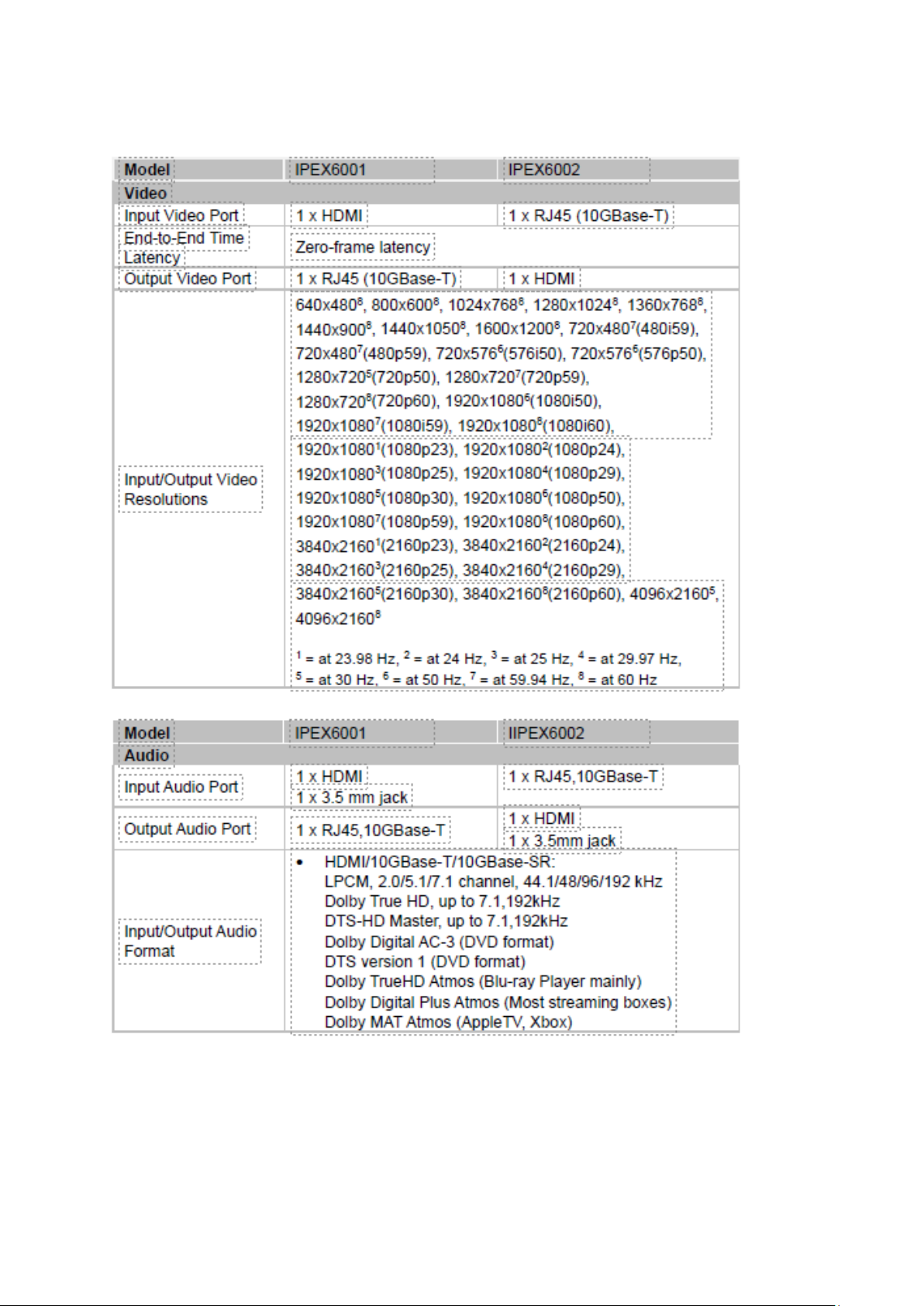
IPEX6001 / 6002 Technical Specifications
Page 17
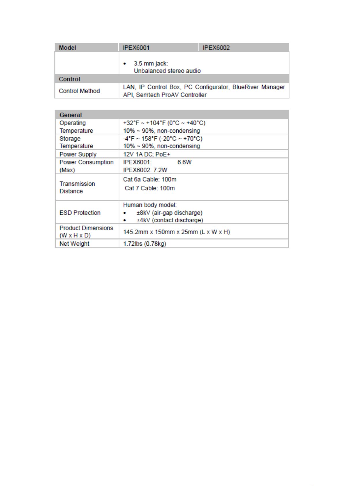
IPEX6001 / 6002 Technical Specifications
Page 18

Thank you for your purchase.
For Technical Support please call our toll free number at
800-530-8998 or email us at [email protected]
www.libav.com
11675 Ridgeline Drive
Colorado Springs, Colorado
80921 USA
Phone: 719-260-0061
Fax: 719-260-0075
Toll-Free: 800-530-8998
 Loading...