

Page 1
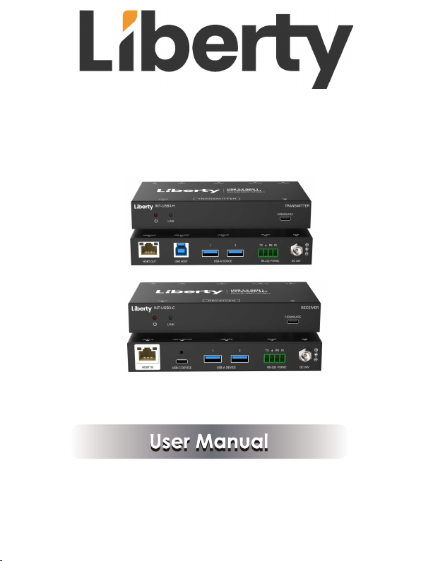
INT-USB3-H & INT-USB3-C
USB 3.2 Gen 1 Extender over HDBaseT
Page 2
Thank you for purchasing this product
For optimum performance and safety, please read these instructions carefully before
connecting, operating or adjusting this product. Please keep this manual for future reference.
Surge protection device recommended
This product contains sensitive electrical components that may be damaged by electrical
spikes, surges, electric shock, lighting strikes, etc. Use of surge protection systems is
highly recommended in order to protect and extend the life of your equipment.
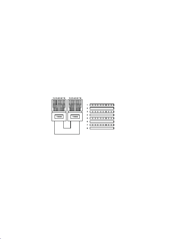
Connection
Please connect in direct interconnection method and do not cross connect.
White and Orange
Orange
White and Green
Blue
White and Blue
Green
White and Brown
Brown
Direct Interconnection Method
Table of Contents
1. Introduction............................................................................................................
2. Features..................................................................................................................
3. Package Contents................................................................................................
4. Specifications.......................................................................................................
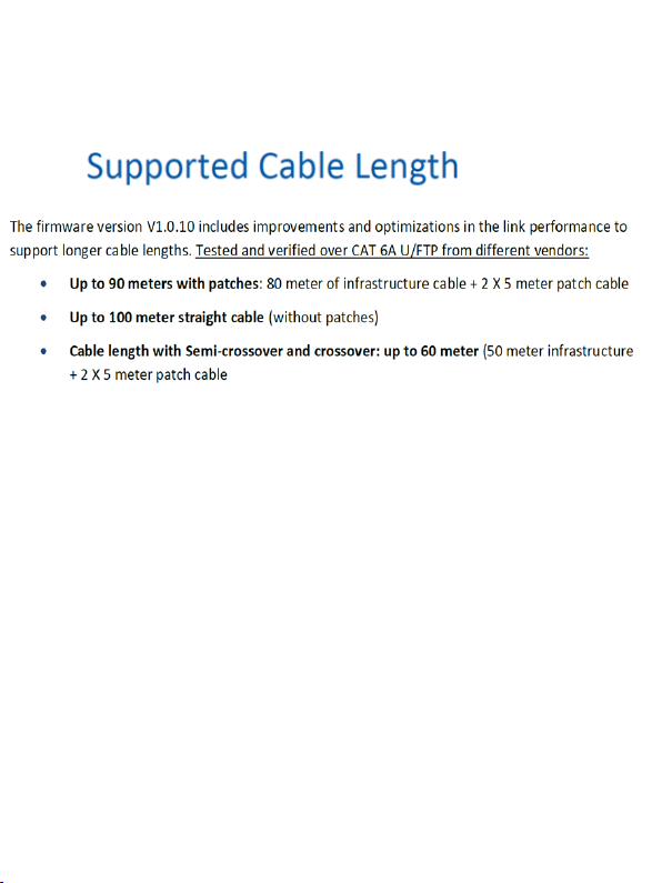
4.1 Supported Cable Length
Operation Controls and Functions......................................................................
5.
5.1 Transmitter Panel.............................................................................................
5.2 Receiver Panel.................................................................................................
Application Example............................................................................................
6.
Page 3

1. Introduction
This USB 3.2 Extender based on HDBaseT VS6320, can extend USB signal to a distance up
to 100m/328ft via a single CAT6a cable. Host/Local device features one USB 3.2 Type B host
port, two USB 3.2 Type A client ports, one FSYSNC
device features one USB 3.2 Type C, and two USB 3.2 Type A client ports, one FSYSNC, and
RS-232 pass-through.
It can be widely used for long distance USB signal transmission between USB sources and
devices like webcams, PTZ cameras, keyboards, mouse devices, USB microphones, flash
sticks, printers, scanners, touch panel displays and other USB devices. Host & Client devices
are sold separately, and are fully compatible with box and wall plate style INT-USB3 devices
Bi-directional 24V Power (PoC) is also supported.
and RS-232 pass-through. Client/Remote
2. Features
☆ Extension of USB 3.2 up to 100m/328ft over CAT6a cable
☆ USB 3.2 Gen 1 connectivity with data transfer rate up to 5Gbps
☆ Backwards compatible with USB 2.0 and 1.1
☆ Hardware acceleration for isochronous and bulk transfer
☆ Each USB-A or USB-C port supports power output up to 5V/1500mA
☆ Plug-and-play with no drivers, downloads, or software required
☆ Support RS-232 pass-through and FSYNC GPIO pass-through (for industry
camera use)
☆ Support bi-directional 24V PoC (Power over Cable)
3. Package Contents
INT-USB3-H INT-USB3-C
USB 3.2 Extender Box (Host)
24V/2.7A Power Supply
USB-C to USB-B cable (2m)
USB-A to USB-B cable (2m)
Mounting Ear
4pin-3.5mm Phoenix Connector
Qty Qty
USB 3.2 Extender Box (Client)
1
AC Power Cord (1.5m)
2
USB-A to USB-A cable (2m)
1
USB-A to USB-C cable (2m)
1
4
Machine Screw (KM3*4)
User Manual
2
1/6
1
2
1
1
8
1
Page 4

4. Specifications
Technical
USB Protocol
Transmission Rate Up to 5Gbps
Transmission Distance
ESD Protection
Connections
Transmitter
Receiver
Mechanical
Housing
Color
Dimensions
Weight
Power Supply
Power Consumption
Operating Temperature
Storage Temperature
Relative Humidity 20~90% RH (non-condensing)
Country of Origin
USB 3.2 Gen 1
Up To 100m/328ft over CAT6a (U/FTP) cable
IEC 61000-4-2:
±8kV (Air-gap discharge), ±4kV (Contact discharge)
×
Input: 1
Output: 2
Control: 1
Input: 1× HDBT IN [RJ45 connector, 24V PoC]
Output: 2
Control: 1
Metal Enclosure
Black
Transmitter / Receiver: 75mm [W] × 140mm [D] × 23mm [H]
Transmitter: 60g / Receiver: 50g
Input: AC 100~240V 50/60Hz
Output: DC 24V/2.7A
PoC Power Supply: 48W (Max)
0°C ~ 40°C / 32°F ~ 104°F
-20°C ~ 60°C / -4°F ~ 140°F
Taiwan (TAA Compliant)
USB HOST [USB Type B, 9-pin female]
×
USB-A DEVICE [USB Type A, 9-pin female]
1
×
HDBT OUT [RJ45 connector, 24V PoC]
× RS-232 [
1
× FSYNC [
1× FIRMWARE [USB-C, firmware update port]
×
1
×
× RS-232 [
1
× FSYNC [
1× FIRMWARE [USB-C, firmware update port]
3pin-3.5mm phoenix connector
1pin-3.5mm phoenix connector
USB-A DEVICE [USB Type A, 9-pin female]
USB-C DEVICE [USB Type C, 24-pin female]
3pin-3.5mm phoenix connector
1pin-3.5mm phoenix connector
]
]
]
]
2/6
Page 5
4.1
** Important note. "EZ" or other types of pass-through RJ45
connectors are not supported. Please use quality shielded RJ45
connectors that properly pair with the Cat6a or above cable
being used
Page 6
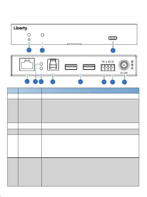
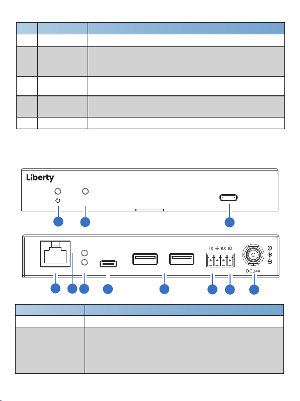
5. Operation Controls and Functions
5.1 Transmitter Panel
INT-USB3-H
1
HDBT OUT USB HOST
4
No. Function DescriptionName
Power LED
1
LINK LED
2
3
FIRMWARE
4
HDBT OUT
LINK LED
5
6
DATA LED
FIRMWARE
LINK
2
LINK
DATA
5
6
7
1 2
USB-A DEVICE
8
RS-232 FSYNC
9
10 11
3
The LED will be on when the transmitter is powered on.
Connection signal indicator.
▪ On: Transmitter and Receiver are connected and linked.
▪ Blinking: Transmitter and Receiver link is off due to USB low
power mode.
▪ Off: Transmitter and Receiver are not connected.
Firmware update port.
Connects to the HDBT IN port on Receiver with CAT cable.
Connection signal indicator.
▪ On: Transmitter and Receiver are connected and linked.
▪ Blinking: Transmitter and Receiver link is off due to USB low
power mode.
▪ Off: Transmitter and Receiver are not connected.
USB signal indicator.
▪ On: When the USB HOST port establishes an USB 3.2
connection to an USB host.
▪ Blinking: When the USB HOST port establishes an USB 2.0
connection to an USB host.
▪ Off: The USB HOST port is not connected.
3/6
TRANSMITTER
Page 7
No. Function DescriptionName
USB HOST
7
USB-A DEVICE
8
(1~2)
9
RS-232
FSYNC
10
DC 24V DC 24V/2.7A power input port.
11
Host port supporting USB 3.2 Gen1, connected to a PC or host.
USB extended interface, connected to USB devices such as
U disk, keyboard or mouse.
And its output power is up to 5V/1.5A.
3pin phoenix connector, connected to a PC or control system
for RS-232 command pass-through.
FSYNC port, the level pass through from Transmitter to Receiver,
to synchronize the external devices. Default level range is 0~5V.
5.2 Receiver Panel
INT-USB3-C
1
HDBT IN
4
No. Function DescriptionName
Power LED
1
LINK LED
2
FIRMWARE
LINK
2
LINK
DATA
USB-C DEVICE
5
6
7
1 2
USB-A DEVICE
8
RS-232 FSYNC
9
10 11
3
The LED will be on when the receiver is powered on.
Connection signal indicator.
▪ On: Transmitter and Receiver are connected and linked.
▪ Blinking: Transmitter and Receiver link is off due to USB low
power mode.
▪ Off: Transmitter and Receiver are not connected.
4/6
RECEIVER
Page 8

No. Function DescriptionName
FIRMWARE
3
4
HDBT IN
LINK LED
5
6
DATA LED
USB-C DEVICE
7
USB-A DEVICE
8
(1~2)
RS-232
9
10
FSYNC
11
DC 24V
Firmware update port.
Connects to the HDBT OUT port on Transmitter with CAT cable.
Connection signal indicator.
▪ On: Transmitter and Receiver are connected and linked.
▪ Blinking: Transmitter and Receiver link is off due to USB low
power mode.
▪ Off: Transmitter and Receiver are not connected.
USB signal indicator.
▪ On: The USB HOST port establishes an USB 3.2 connection
to an USB host, and the USB DEVICE port
(USB-C or USB-A)
establishes an USB 3.2 connection to an USB device.
▪ Blinking: The USB HOST port establishes an USB 2.0
connection to an USB host, and the USB DEVICE port (USB-C
or USB-A) establishes an USB 2.0 connection to an USB device.
▪ Off: The USB Device port is not connected.
USB type C port supporting USB 3.2 Gen 1, connected to USB
device. And its output power is up to 5V/1.5A.
USB type A port supporting USB 3.2 Gen 1, connected to USB
device. And its output power is up to 5V/1.5A.
3pin phoenix connector, connected to a PC or control system
for RS-232 command pass-through.
FSYNC port. Outputs the level from Transmitter to synchronize
the external devices. Default level range is 0~5V.
DC 24V/2.7A power input port.
5/6
Page 9
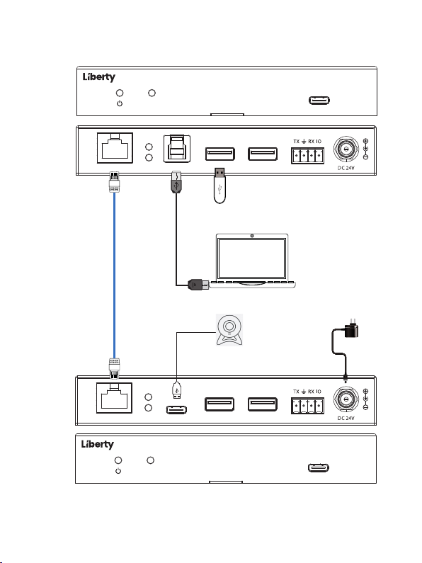
6. Application Example
Transmitter
Receiver
HDBT OUT USB HOST
CAT6a
HDBT IN
INT-USB3-C
INT-USB3-H
TRANSMITTER
LINK
LINK
DATA
1 2
USB-A DEVICE
FIRMWARE
RS-232 FSYNC
U Disk
PC
Power Supply
USB Camera
LINK
DATA
USB-C DEVICE
LINK
1 2
USB-A DEVICE
RS-232 FSYNC
RECEIVER
FIRMWARE
6/6
Page 10

 Loading...