

Liberty XL2 Maintenance Manual
Maintenance Manual
1383 General Aviation Drive
Melbourne, FL 32935
800-759-5953
Table of Contents
XL2 Airplane
Table of Contents
Record of Revision iii
Check List iv
List of Temporary Revisions v
List of Service Bulletins vi
Table of Chapters
General
Introduction 01
General Description 03
Airworthiness Limitations 04
Time Limits/Maintenance Checks/Inspection
Intervals 05
Dimensions and Areas 06
Lifting and Jacking 07
Leveling and Weighing 08
Towing and Taxiing 09
Parking and Mooring 10
Required Placards 11
Servicing 12
Equipment
Standard Practices-Airframe 20
Environmental Systems 21
Communications 23
Electrical Power 24
Equipment and Furnishings 25
Flight Controls 27
Fuel System 28
Indication and Recording Systems 31
Landing Gear 32
Lights 33
Navigation and Pitot/Static 34
Chapters
Chapters

Table of Contents
XL2 Airplane
Airframe
Chapters
Structures 51
Doors 52
Fuselage 53
Stabilizers 55
Windows 56
Wings 57
Propeller
Chapter
Propeller 61
Power Plant
Chapters
Standard Practices-Engine 70
Power Plant 71
Engine 72
Engine Fuel System 73
Ignition 74
Engine Air 75
Engine Controls 76
Engine Indicating 77
Exhaust 78
Oil 79
Starting 80
Wiring Diagrams 91
Revision
Number
Original Issue April 2005 All
1 April 2005 4-2, 4-4
2 May 2005
Record of Revisions
Date Affected Pages
Replace: 5- Inspection Check list pg.,
5,6,7. 31-Table of Contents. Add: 31-10
iii

Check List
This Check List should be used for control of all revisions issued and installed in
this manual. The affected pages of any revision, as well as the Record of
Revisions must be inserted into the manual upon receipt. The pages superseded
by the revision must be removed and destroyed. The Check List should be
updated by hand. Changes are identified on those pages affected by a revision
bar.
Revision
Number:
Date
Issued:
Inserted
On:
Inserted
By:
Revision
Number:
iv
Date
Issued:
Inserted
On:
Inserted
By:
List of Temporary Revisions
Revision
Number:
Date
Issued:
Inserted
on:
Inserted
By:
Revision
Number:
v
Date
Issued:
Inserted
on:
Inserted
By:
List of Service Bulletins
Service
Bulletin:
Revision
Number:
Inserted
On:
Service
Bulletin:
vi
Revision
Number:
Inserted
On:
Introduction
XL2 Airplane
Chapter 01
INTRODUCTION
INITIAL RELEASE
P/N 135A-970-006 - 1 -

Introduction
XL2 Airplane
Introduction
Table of Contents
GENERAL
REVISIONS
WARNINGS, CAUTIONS, NOTES
MANUAL ARRANGEMENT
MAIN CHAPTER GROUPS
3
3
4
4
5
INITIAL RELEASE
P/N 135A-970-006 - 2 -

Introduction
XL2 Airplane
General:
This Maintenance Manual is intended to furnish maintenance personnel with all data
required for normal maintenance of the Liberty XL2 airplane. It comprises detailed
system and subsystem descriptions, troubleshooting tables, component removal,
reinstallation procedures, and detailed maintenance procedures.
Unless otherwise specified, this Maintenance Manual contains only removal and
reinstallation instructions for specific components i.e.: generator, fuel system
components, instruments, etc. Detailed maintenance and service instructions for
individual components are to be obtained from the applicable component
manufacturer’s maintenance manual.
All maintenance work including inspections, routine maintenance, and repairs are to
be performed in accordance with the procedures set forth in this Maintenance
Manual.
Other documentation to be used with this manual includes, but is not limited to:
Liberty XL2 Approved Flight Manual/Pilot Operating Handbook (AFM/POH).
Operator’s Manual for TCM IOF-240 Engine p/n: OI-22.
Maintenance Manual for TCM IOF-240 Engine, TCM p/n: M-22.
Maintenance Manual for Sensenich W69EK7-63G Propeller.
Operator’s manuals for avionics components installed on the airplane.
Revisions:
The revision number and date of original issue or revision of each page of this
Maintenance Manual is printed at the foot of each page. A Record of Revisions is
provided at the front of the manual. A Page Control sheet is provided to verify the
status of each page of this manual. A new Page Control sheet is provided with each
revision.
Liberty Aerospace, through document 135A-995-221, Product Support and Service
Difficulties, provides a method for communication with customers using service
letters and service bulletins.
A Record of Revisions is provided to allow verification that all revisions have been
entered in a timely manner.
The Maintenance Manual will be reissued in its entirety from time to time as number
and volume of revisions warrant.
INITIAL RELEASE
P/N 135A-970-006 - 3 -

Introduction
XL2 Airplane
Changed Text:
Changes to text as a result of revisions are indicated by a vertical line in the margin
adjacent to the text that has been changed.
Blank Pages:
Blank pages may appear in either originally issued or revised sections of the
Maintenance Manual. They are identified by the legend:
PAGE LEFT INTENTIONALLY BLANK
in the center of each page.
Warnings, Cautions, Notes:
The following definitions apply to Warnings, Cautions, and Notes found throughout
this Maintenance Manual:
WARNING:
AN OPERATING PROCEDURE, INSPECTION, REPAIR OR MAINTENANCE PR ACTICE, WHICH
IF NOT CORRECTLY FOLLOWED, COULD RESULT IN PERSONAL INJURY OR LOSS OF LIFE.
CAUTION:
AN OPERATING PROCEDURE, INSPECTION, REPAIR OR MAINTENANCE PRACTICE, WHICH IF
NOT STRICTLY OBSERVED COULD RESULT IN DAMAGE OR DESTRUCTION OF EQUIPMENT.
NOTE:
An operating procedure, inspection, repair or maintenance condition, etc, which is
deemed essential to highlight.
Manual Arrangement:
The overall arrangement of this Maintenance Manual is in accordance with the Air
Transport Association of America (ATA) Specification number: 100 and the General
Aviation Manufacturers Association (GAMA) Specification number: 2. The title of
each chapter can be found in the general Table of Contents located at the front of
the manual, and on the divider tabs separating the chapters.
Each main system is covered by a specific chapter which is subdivided into sections
describing relevant subsystems.
INITIAL RELEASE
P/N 135A-970-006 - 4 -

Introduction
XL2 Airplane
The chapters are combined in main groups as follows:
GENERAL Chapters 01 - 12
EQUIPMENT Chapters 20 - 34
AIRFRAME Chapters 51 - 57
PROPELLER Chapter 61
ENGINE Chapters 71 - 92
Each of the main groups as well as each chapter is divided by a cover page showing
chapter number and the title.
INITIAL RELEASE
P/N 135A-970-006 - 5 -

General Description
XL2 Airplane
CHAPTER 03
GENERAL DESCRIPTION
P/N 135A-970-006 Chap 03
INITIAL RELEASE - 1 -
General Description
XL2 Airplane
Chapter 03
Table of Contents
Chapter 03
Table of Contents 2
Chapter 03-00
General 3
Description 3
Vendor
Documentation 4
P/N 135A-970-006 Chap 03
INITIAL RELEASE - 2 -

General Description
XL2 Airplane
General Description
General:
The Liberty XL2 airplane is manufactured by
Liberty Aerospace, Inc.
1383 General Aviation Drive
Melbourne, Florida, USA, 32935
1-800-759-5953
and is approved in the normal airworthiness category.
The XL2 may be operated under DAY or NIGHT VFR conditions depending on
installed standard and optional equipment. IFR certification is pending.
Description:
The Liberty XL2 airplane is a low-wing two-place aircraft with tricycle landing gear.
Its central structural element is a welded steel tubing frame or “chassis” which has
the following components attached:
• Engine and Propeller
• Wings (conventional aluminum construction)
• Main landing gear (aluminum construction)
• Nose landing gear (steel construction)
• Fuselage (composite construction), including;
• Aft fuselage with vertical fin (composite construction)
• Rudder and stabilators (aluminum construction)
• Center fuselage including crew/passenger cabin, fuel tank, and baggage
compartment
• Engine cowlings.
The wings are bonded aluminum semimonocoque structures, and are secured to the
chassis by means of heavy steel pins in attach fittings. With the wing or wings
removed the fuselage remains supported by the landing gear. The removable
aluminum horizontal tail is a stabilator type in which the entire unit moves to change
pitch on the aircraft. The only movable surfaces on the horizontal tail are the antiservo tabs which are used for both pitch trim and anti-servo functions.
The composite vertical fin is integrated into the fuselage structure; the rudder is an
aluminum structure.
Ailerons and stabilators are operated by pushrods from cockpit control sticks.
P/N 135A-970-006 Chap 03-00
INITIAL RELEASE - 3 -

General Description
XL2 Airplane
The rudder is operated by pushrods attached to adjustable cockpit rudder pedal
assemblies. Aluminum trailing edge flaps are electrically operated.
The XL2 is powered by an air-cooled Teledyne Cont inental Motors IOF-240-B four
cylinder, horizontally opposed, fuel injected engine. The engine is rated at 125
continuous SAE horsepower at 2800 RPM. The engine is equipped with a Full
Authority Digital Engine Control (FADEC) system to control ignition timing and fuel
mixture without pilot intervention. Fuel is supplied from a single 28 gallon capacity
aluminum tank. It is installed in the fuselage between the pilot/passenger seatbacks
and the baggage compartment. The propeller is fixed pitch, constructed of wood
and fiberglass made by Sensenich p/n: W69EK7 63G.
Vendor Documentation:
Engine:
Teledyne Continental Motors, IOF-240-B
2039 Broad Street
Mobile, AL. 36615
Tel: 251-438-3411
Fax: 251-432-7352
www.tcmlink.com
Propeller:
Sensenich, W69EK7-63G
14 Citation Lane
Lititz, PA. 17543
Tel: 717-569-0435
Fax: 717-560-3725
www.sensenich.com
Main Wheel Brakes:
Parker-Hannifin, Aircraft Wheel & Brakes
1160 Center Road
Avon, OH. 44011-0158
Tel: 440-937-6211
Fax: 440-937-6416
Navigation and Communication Equipment:
Garmin International Inc.
1200 East 151
Olathe, KS. 66062
Tel: 913-397-8200
Fax: 913-397-8282
Apollo Aircraft products Tel: 503-391-3411 ext. 3991
st
Street
P/N 135A-970-006 Chap 03-00
INITIAL RELEASE - 4 -
General Description
XL2 Airplane
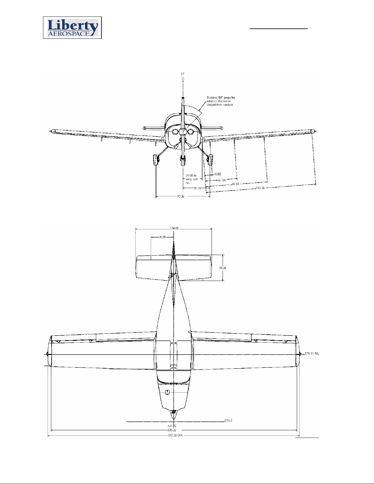
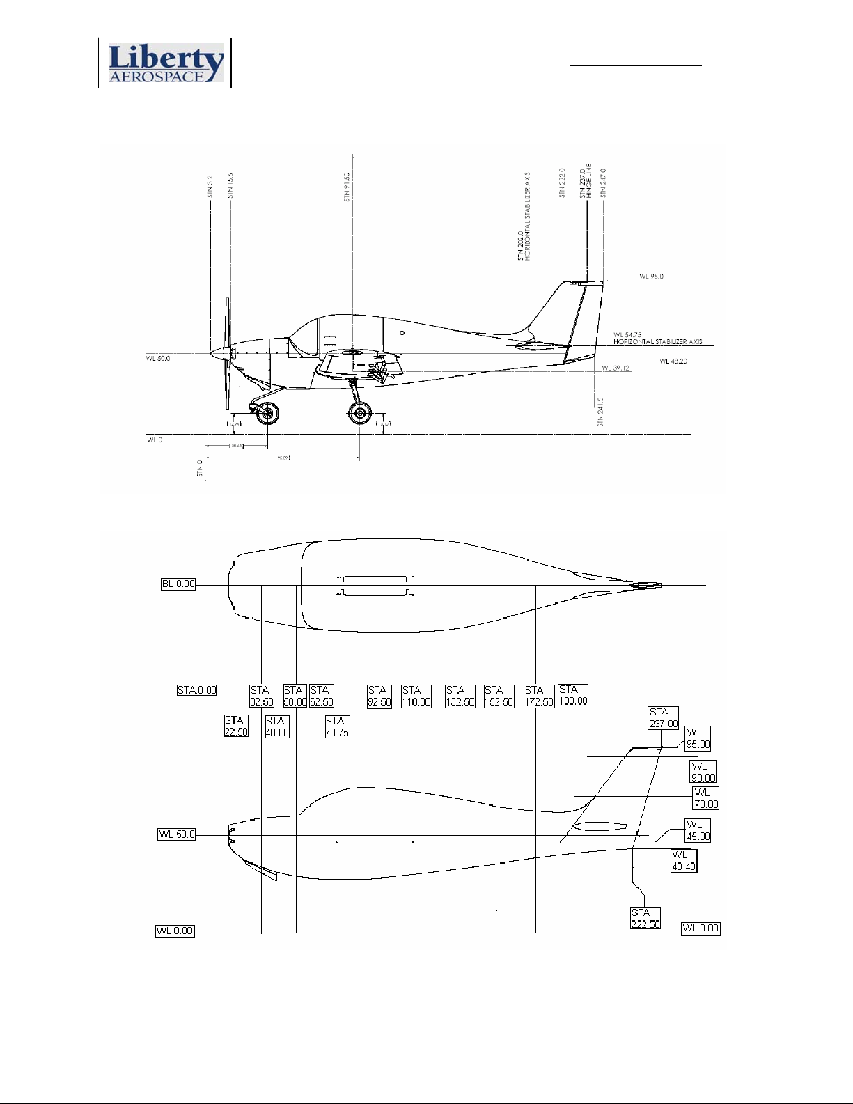
Aircraft measurements:
P/N 135A-970-006 Chap 03-00
INITIAL RELEASE - 5 -
General Description
XL2 Airplane
P/N 135A-970-006 Chap 03-00
INITIAL RELEASE - 6 -
General Description
XL2 Airplane
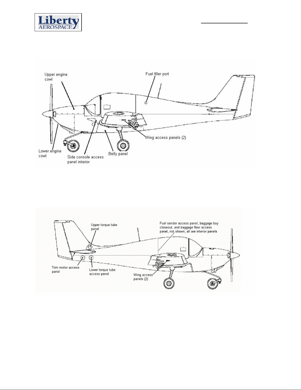
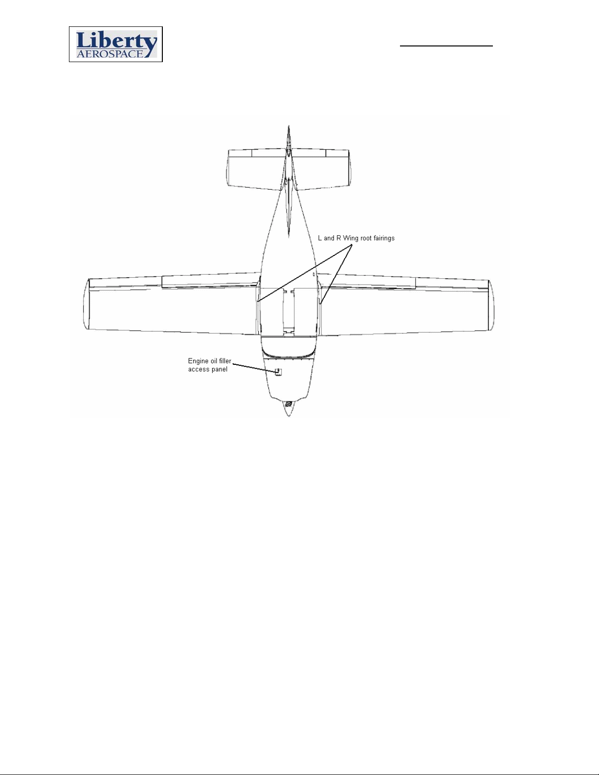
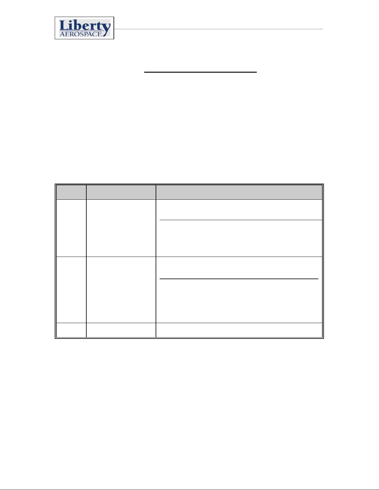
Aircraft access panels.
P/N 135A-970-006 Chap 03-00
INITIAL RELEASE - 7 -
General Description
XL2 Airplane
P/N 135A-970-006 Chap 03-00
INITIAL RELEASE - 8 -

Airworthiness Limitations
XL2 Airplane
CHAPTER 04
AIRWORTHINESS LIMITATIONS
P/N 135A-970-006 Page 4 - 1
April 2005
04-TITLE
Airworthiness Limitations
XL2 Airplane
The Airworthiness Limitations Section is FAA approved and specifies inspections
and other maintenance required under paragraphs 43.16 and 91.403 of the
Federal Aviation Regulations unless an alternative program has been FAA
approved.
REV
IR
DATE
FEB. 19, 2004
A
AIRWORTHINESS LIMITATIONS
APPROVED
/s/ Ronald F. May
Ronald F. May, Manager
Denver Aircraft Certification Office
Federal Aviation Administration
Northwest Mountain Region
.
Melvin D. Taylor, Manager
Atlanta Aircraft Certification Office
Federal Aviation Administration
Southeast Region
P/N 135A-970-006 04-00-00 Page 4 - 2
April 2005

Airworthiness Limitations
XL2 Airplane
SECTION 04-10:
AIRFRAME
The structural inspection procedures and inspection intervals for both life limited
components and components subject to a more detailed level of inspection are
listed below in Section 4-20.
P/N 135A-970-006 04-00-00 Page 4 - 3
April 2005
Airworthiness Limitations
XL2 Airplane
SECTION 04-20:
COMPONENTS SUBJECT TO LIFE LIMITS OR REQUIRING MORE
DETAILED LEVELS OF INSPECTION
Items listed below are considered components that are either life-limited with
distinct times between replacement, or components subject to a higher level of
inspection. The life-limited components must be removed from service at the
replacement times indicated and rendered unserviceable and discarded to
prevent re-use.
Note
: Record new aircraft serial number, hours and at installation and removal.
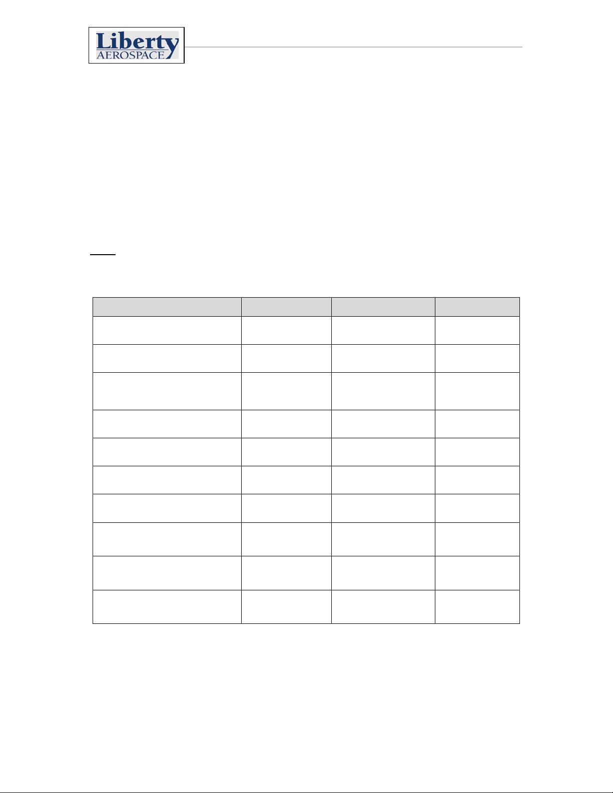
COMPONENTS SUBJECT TO LIFE-LIMITS
Component P/N Inspection Interval
Fuselage and Chassis
Wing Skin and Spar
Wing Root Fittings
Wing Carry Through Structure 135A-10-075
Nose Lock Pin 135A-40-565
Tail Plane Mass Balance Drive Arm 135A-45-615
Tail Plane Attachment Lug 135A-30-591
Firewall 33M1154-301
135A-00-025
135A-10-035
135A-20-005
135A-20-006
135A-10-085
135A-10-086
135A-20-501
135A-20-502
Annual for all aircraft and
100 hr as applicable per
Part 91
Annual for all aircraft and
100 hr as applicable per
Part 91
Annual for all aircraft and
100 hr as applicable per
Part 91
Annual for all aircraft and
100 hr as applicable per
Part 91
Annual for all aircraft and
100 hr as applicable per
Part 91
Annual for all aircraft and
100 hr as applicable per
Part 91
Annual for all aircraft and
100 hr as applicable per
Part 91
Annual for all aircraft and
100 hr as applicable per
Part 91
Mandatory
Replacement Time
225 hrs
9800 hrs
5250 hrs
1500 hrs
500 hrs
500 hrs
500 hrs
Annual
FADEC Backup Battery RG-1207 Annual for all aircraft Annual
FADEC Backup Battery 656070 Annual for all aircraft Annual
P/N 135A-970-006 04-20-00 Page 4 - 4
April 2005
Airworthiness Limitations
XL2 Airplane
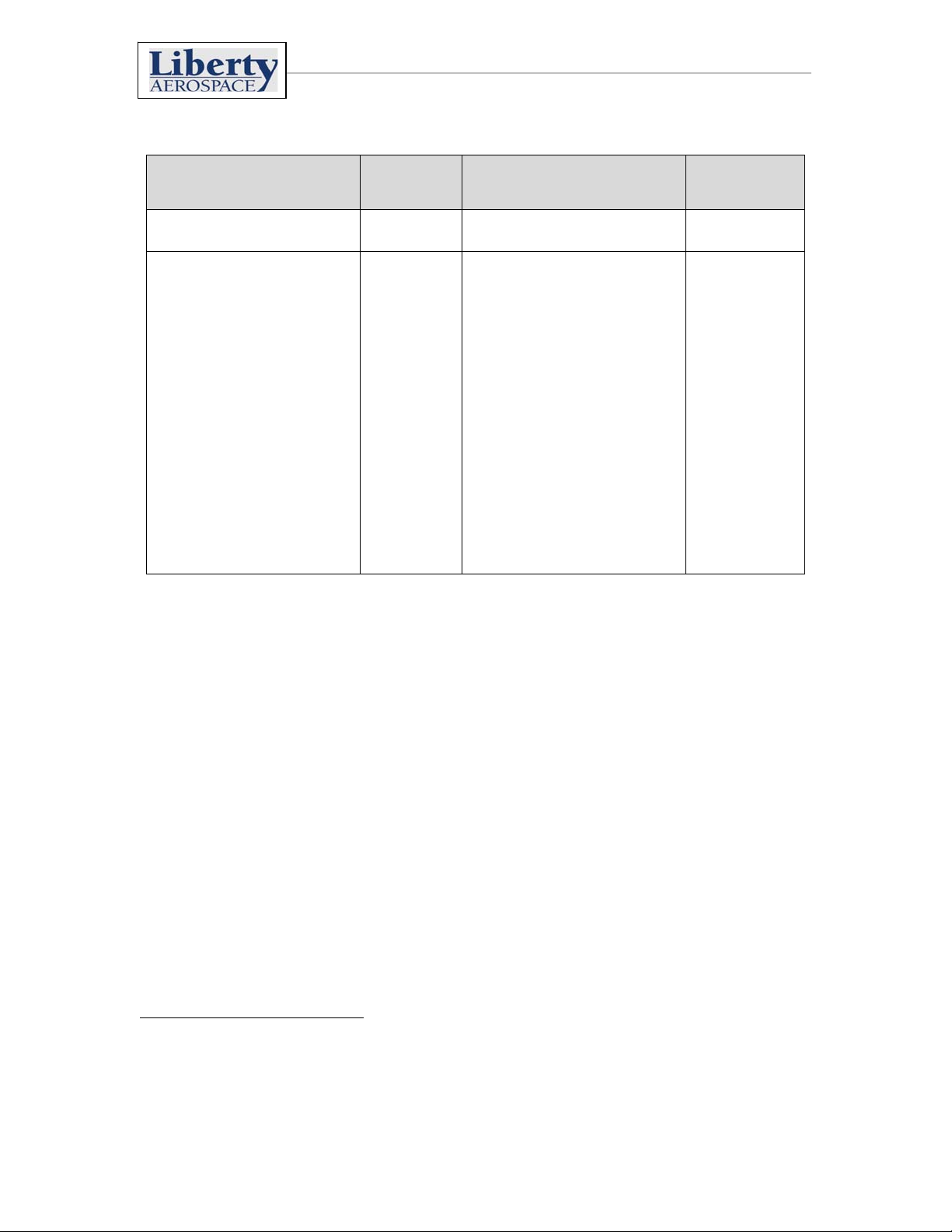
COMPONENTS REQUIRING A MORE DETAILED LEVEL OF INSPECTION
Mandatory
Component P/N Inspection Interval
Throttle Control System
Composite Fuselage
2
1
135A-50-015
135A-10-105
Annual for all aircraft and 100 hr
as applicable per Part 91
Inspection Type: Visual
Inspection of all fuselage bondlines and the fuselage structure
Inspection interval: Prior to each
flight
Inspection Type: Tap test
inspection of all fuselage bondlines and fuselage-laminate for
damage. Associated inspection
interval: Annual for all aircraft
and 100 hr as applicable per part
91
Date of removal and replacement of life-limited components, including flight
hours, must be recorded in aircraft maintenance records to ensure correct
observation of the stated interval(s).
Replacement
Time
None
225 hrs
1
The inspection procedure for the XL2 throttle cable installation will be conducted as directed in
Chapter 5 of these Instructions for Continued Airworthiness.
2
The inspection procedure for the XL2 fuselage will be conducted as directed in Chapter 5 of
these Instructions for Continued Airworthiness.
P/N 135A-970-006 04-20-00 Page 4 - 5
April 2005
Airworthiness Limitations
XL2 Airplane
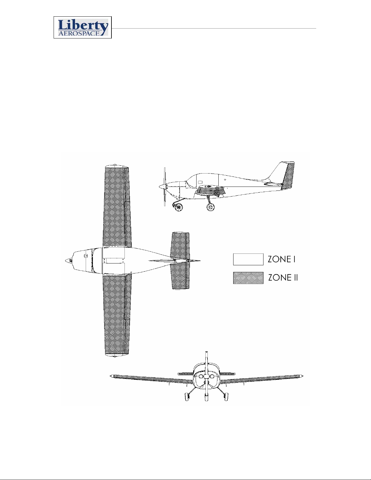
SECTION 04-30
PAINT FINISH
To ensure that the temperature of the load-bearing composite structure is kept
below the structural temperature limit, the outer surface of the composite
components must be painted white except for areas of registration marks,
placards, and minor trim. Figure 4.1 defines the zones and limitations for exterior
paint color.
1. Zone I: These areas are composite and therefore must be painted white.
2. Zone II: These areas are metallic and therefore may be painted any color.
Figure 4.1 Paint Zones
P/N 135A-970-006 04-30-00 Page 4 - 6
April 2005

Time Limits/Maintenance Checks/Inspection Intervals
CHAPTER 05
TIME LIMITS/MAINTENANCE CHECKS/INSPECTION
INTERVALS
XL2 Airplane
INITIAL RELEASE - 1 -
P/N 135A-970-006 Chap 05
Time Limits/Maintenance Checks/Inspection Intervals
XL2 Airplane
Chapter 05
Table of Contents
Chapter 05
Table of Contents
Chapter 05-00
General
Chapter 05-10
Time Limits
Chapter 05-20
General
50, 100, and 500 hour inspections, checklist
Check Flight checklist
Chapter 05-30
General Inspections
General
Preflight Inspections
Post-Flight Inspections
Chapter 05-40
Unscheduled Inspections
General
Special Inspections
2
1
1
1
1
1
1
1
1
1
1
P/N 135A-970-006 Chap 05-
INITIAL RELEASE - 2 -

Time Limits/Maintenance Checks/Inspection Intervals
XL2 Airplane
Time Limits/Maintenance Checks/Inspection Intervals
Section 05-00
General:
Maintenance personnel should refer to chapters 04 and 05 as guidelines for proper
scheduling and execution of inspections and maintenance.
The inspections and intervals described in these two chapters are considered the
minimum required to maintain the airplane in airworthy condition.
WARNING:
TO PREVENT INJURY TO PERSONNEL, ENSURE THAT THE PROPELLER AREA IS CLEAR OF
ANY PERSON IN THE EVENT THAT ANY INSPECTION OR MAINTENANCE MUST BE
PERFORMED WITH THE MASTER AND EITHER FADEC “A” OR FADEC “B” SWITCH “ON”,
BATTERY CONNECTED AND THE PROPELLER BEING MOVED. IF IGNITION SWITCH OR
GROUND WIRE IS DEFECTIVE, UNINTENTIONAL ENGINE FIRING OR RUNNING IS POSSIBLE
EVEN WITH THE IGNITION SWITCH “OFF”.
P/N 135A-970-006 Chap 05-00
INITIAL RELEASE - 1 -

Time Limits/Maintenance Checks/Inspection Intervals
Section 05-10
Time Limits:
Component time limits:
Component Specified Time Between Overhaul
Engine, Teledyne Continental
Motors, model IOF-240-B.
Including accessories 2000 operating hours or 12 years
Propeller, Sensenich model
W69EK7-63G To be inserted
XL2 Airplane
P/N 135A-970-006 Chap 05-20
INITIAL RELEASE - 1 -
 Loading...