

Page 1
MySignals
User Manual
Page 2
Index
© Libelium Comunicaciones Distribuidas S.L.
INDEX
1. Introduction ......................................................................................................................................... 3
2. General and safety information ......................................................................................................... 3
3. MySignals’s Hardware Setup .............................................................................................................. 4
3.1. Power Supply .................................................................................................................................................................................4
3.2. Sensors .............................................................................................................................................................................................5
3.3. Data Visualization ......................................................................................................................................................................10
3.4. Mini USB Data Transfer ............................................................................................................................................................ 11
3.5. Wireless Communication ...................................................................................................................................................... 11
4. MySignals Software Installation ...................................................................................................... 11
4.1. MySignals Updater Tool .......................................................................................................................................................... 11
4.2. MySignal Web Server Application .......................................................................................................................................12
4.3. MySignals Mobile APP .............................................................................................................................................................12
5. Accessing MySignals Data................................................................................................................. 13
5.1. MySignals Standalone Screen .............................................................................................................................................. 14
5.2. MySignals Web Server Application .....................................................................................................................................15
5.3. MySignals Mobile APP .............................................................................................................................................................18
6. Updating a New Firmware to MySignals .......................................................................................... 20
6.1. MySignals Updater Tool ......................................................................................................................................................... 20
7. Certications Information ................................................................................................................ 20
7.1. USA and Canada Certication ............................................................................................................................................. 21
-2-
Page 3
1. Introduction
The aim of this manual is to introduce the user to MySignals in a practical way.
This document applies to MySignals product, approved for FCC and IC:
Model FCC ID IC
MySignals XKM-MYSIGNAL-V1 8472A-MYSIGNALV1
2. General and safety information
The following list shows just some of the actions that produce the most common failures and warranty-voiding cases.
Failure to comply with the recommendations of use will entail the guarantee cancellation.
Software:
• Update rmware version only using MySignals Updater Tool. If a dierent Software is used, MySignals can be damaged
and can become unresponsive. This use is not covered under warranty.
• Use only MySignal Web Server Application or MySignals Mobile APP in order to congure and setup your account and
device.
• Do not unplug any connector while uploading code. MySignals can become unresponsive. This use is not covered under
warranty.
• Do not connect or disconnect any sensor or connector while MySignals is ON. MySignals can become unstable or
unresponsive, and internal parts can be damaged. This fact is not covered under warranty.
Hardware:
• Do not handle black stickers seals on both sides of the enclosure (Warranty stickers). Their integrity is the proof that
MySignals has not been opened. If they have been handled, damaged or broken, the warranty is void.
• Do not open MySignals in any case. This will automatically make the warranty void.
• Do not handle the four metallic screws of MySignals.
• Do not submerge MySignals in liquids.
• Do not place nodes on places or equipment where it could be exposed to shocks and/or big vibrations.
• Do not expose MySignals to temperatures below -10ºC or above 50ºC.
• Do not connect any sensor not provided by Libelium.
• Do not power MySignals with other power sources than the original provided by Libelium.
-3-
Page 4
3. MySignals’s Hardware Setup
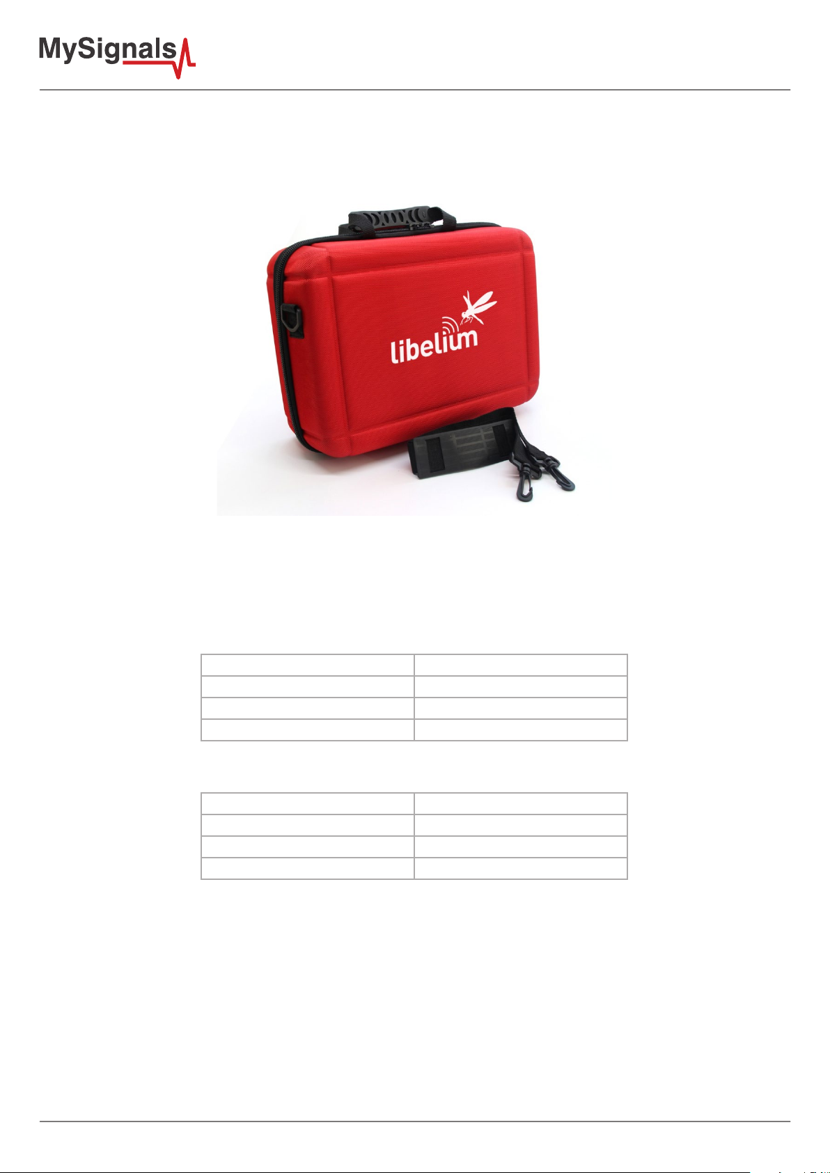
All the items included in the basic kit of MySignals are in their specic compartiments in MySignals briefcase.
Figure : Mysignals briefcase
3.1. Power Supply
General power supply
Operating Current 2 A
Operating Voltage 5V
Input Voltage (recommended) 12V
Input Voltage (limit) 10-20V
Specic power supply
DC Current per I/O Pin 20 mA [Max]
DC Current for 3.3V 1 A [Max]
DC Current for 5V 1 A [Max]
DC Current for 4 V Pin 2 A [Max]
Plug in /out the power supply adapter included with MySignals to turn ON or OFF the device. Make sure that the power adapter
is indoors.
Plug it into the corresponding power supply connector. At Libelium we oer equipment for operating at 12V, do not use other
power supplies.
You can see all the information about the power supply in the label included in MySignals device.
-4-
Page 5
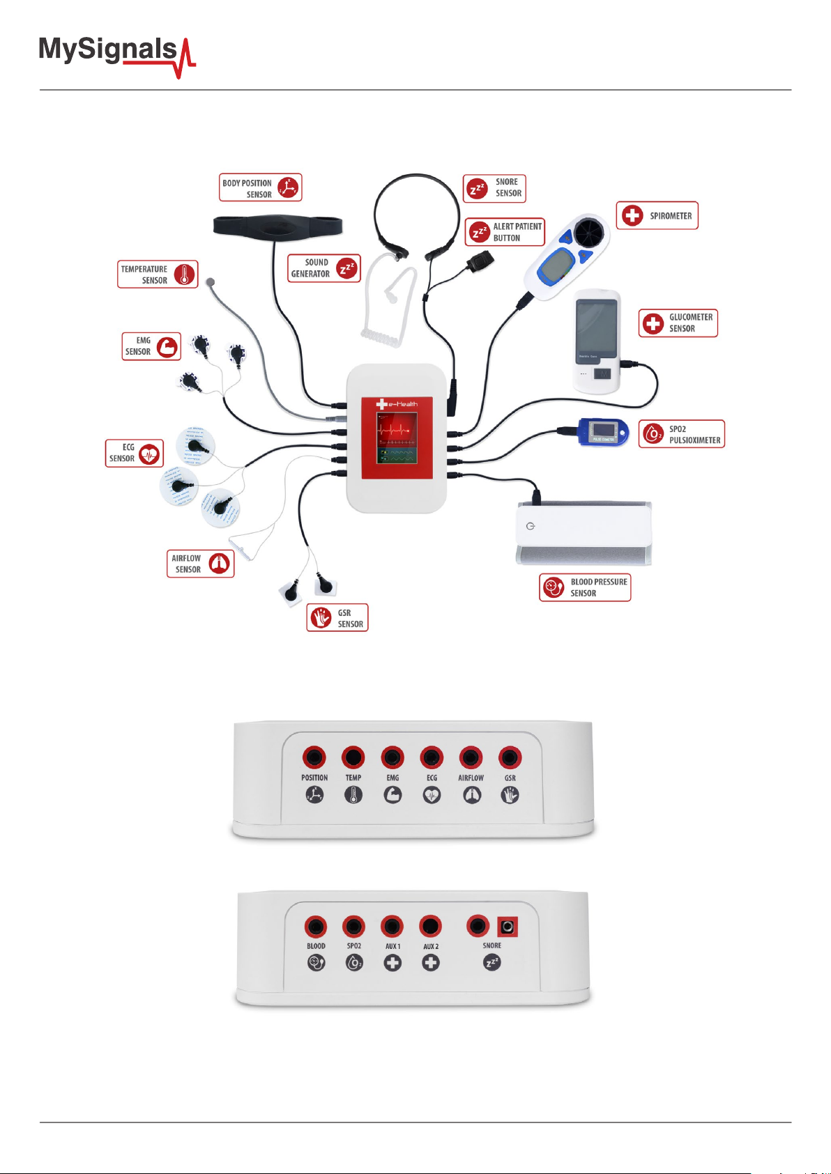
3.2. Sensors
Figure : Mysignals sensors
You can nd all the sensor connectors indicated in both sides of the device.
Figure : Mysignals sensor connectors
-5-
Page 6
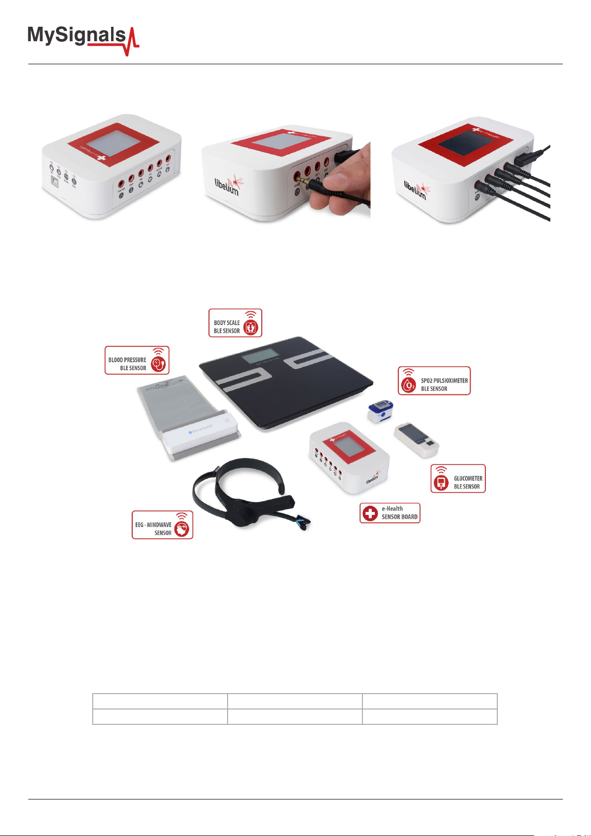
Connect the correct sensor in each specic connector as you can see in the following images:
Figure : Connecting one sensor
This information is used to monitor in real time the state of a user or to get sensitive data in order to be subsequently analysed
for biometric analysis. Biometric information gathered can be wirelessly sent using two connectivity options available: Wi-Fi or
Bluetooth Low Energy 4.0.
Figure : MySignals BLE sensors
Data can be sent to the Cloud in order to perform permanent storage or visualized and storaged in real time by sending the
data directly to a Smartphone. iPhone and Android applications have been designed in order to easily manage and storage the
user’s information.
Snore Sensor
Description: This sensor attaches to the neck and records vibration associated with a piezo sensor.
Measurement:
Parameter Unit Range
Respiratory rate BPM (breaths per minute) 0-60 bpm
-6-
Page 7
Patient Position Sensor
Description: The Patient Position Sensor (Accelerometer) monitors ve dierent user positions (standing/sitting, supine, prone,
left and right.). Body Position Sensor uses a triple axis accelerometer to obtain the user’s position.
Measurement:
Parameter Unit Range
Body Position Dimensionless 5 dierent positions
Body Temperature Sensor
Description: Exacon D-S18JK sensor allows you to measure this key parameter for body monitoring.
Measurement:
Parameter Unit Range
Body Temperature Degree Celsius (°C) 0-50ºC
Electromyography Sensor (EMG)
Description: An electromyograph detects the electrical potential generated by muscle cells when these cells are electrically or
neurologically activated. The signals can be analyzed to detect biometric abnormalities, activation level, recruitment order or to
analyze the biomechanics of human or animal movement.
Measurement:
Parameter Unit Range
Muscle signal Volts 0-5V
Electrocardiogram Sensor (ECG)
Description: The electrocardiogram (ECG) is a diagnostic tool that is routinely used to assess the electrical and muscular functions
of the heart. The sensor use “Continuous telemetry electrocardiogram” for a prolonged monitoring including the use of three
ECG electrodes.
Measurement:
Parameter Unit Range
Electrocardiogram signal Volts 0-5V
Airow Sensor (Breathing)
Description: The nasal / mouth airow sensor is a device used to measure the breathing rate in a user in need of respiratory help
or person. This device consists of a exible thread which ts behind the ears, and a set of two prongs which are placed in the
nostrils. Breathing is measured by these prongs.
Measurement:
Parameter Unit Range
Respiratory rate BPM (breaths per minute) 0-60 bpm
Breathing intensity Volts 0-3.3V
-7-
Page 8

Galvanic Skin Response Sensor (GSR - Sweating)
Description: This sensor measures the electrical conductance of the skin, which varies with its moisture level. This is of interest
because the sweat glands are controlled by the sympathetic nervous system, so moments of strong emotion, change the
electrical resistance of the skin.
Measurement:
Parameter Unit Range
Conductance Siemens 0-20Siemens
Resistance Ohms 10K-100KOhms
Voltage Volts 0-5V
Blood Pressure Sensor (Sphygmomanometer)
Description: Blood pressure is the pressure of the blood in the arteries as it is pumped around the body by the heart. When
your heart beats, it contracts and pushes blood through the arteries to the rest of your body. This force creates pressure on the
arteries. Blood pressure is recorded as two numbers—the systolic pressure (as the heart beats) over the diastolic pressure (as
the heart relaxes between beats).
Measurement:
Parameter Unit Range
Systolic pressure mm Hg 0-300 mmHg
Diastolic pressure mm Hg 0-300 mmHg
Pulse ppm 30~200 ppm
Auxiliar input 1
Description: This are generic inputs for possible a UART interface sensors
Auxiliar input 2
Description: This are generic inputs for possible a UART interface sensors
Pulse and Oxygen in Blood Sensor (SPO2)
Description: Pulse oximetry a noninvasive method of indicating the arterial oxygen saturation of functional hemoglobin. Oxygen
saturation is dened as the measurement of the amount of oxygen dissolved in blood, based on the detection of Hemoglobin
and Deoxyhemoglobin. Two dierent light wavelengths are used to measure the actual dierence in the absorption spectra of
HbO2 and Hb.
Measurement:
Parameter Unit Range
Pulse ppm 25~250 ppm
SPO2 % 35-100%
-8-
Page 9

Spirometer
Description: MSA100 Peak Flow Meter is a hand-held pulmonary function measuring device that measures your maximum
possible exhalation which is called peak expiratory ow (PEF) and forced expiratory volume in 1 second (FEV1). FDA,ISO,CE.
Measurement:
Parameter Unit Range
Volume l 0.01L~9.99L
Air ow l/min 50 L/min ~900L/min
Wireless Electroencephalography sensor (EEG)
Description: EEG headset that safely measures and transfers the power spectrum (alpha waves, beta waves, etc) data via
Bluetooth to wirelessly communicate with the device. This headset can be simply slipped on to be able to see your brainwaves
change in real time.
Measurement:
Parameter Unit Range
Brain waves: alpha waves,
beta waves...
Percentage 0-100%
Wireless Blood Pressure Sensor (Sphygmomanometer)
Description: Blood pressure is the pressure of the blood in the arteries as it is pumped around the body by the heart. When
your heart beats, it contracts and pushes blood through the arteries to the rest of your body. This force creates pressure on the
arteries. Blood pressure is recorded as two numbers—the systolic pressure (as the heart beats) over the diastolic pressure (as
the heart relaxes between beats).
Measurement:
Parameter Unit Range
Systolic pressure mm Hg 0-300 mmHg
Diastolic pressure mm Hg 0-300 mmHg
Pulse ppm 30~200 ppm
Pulse and Oxygen in Blood Sensor (SPO2)
Description: Pulse oximetry a noninvasive method of indicating the arterial oxygen saturation of functional hemoglobin.
Oxygen saturation is dened as the measurement of the amount of oxygen dissolved in blood, based on the detection of Hemo
and Deoxy.
Measurement:
Parameter Unit Range
Pulse ppm 25~250 ppm
SPO2 % 35-100%
-9-
Page 10

Wireless Body Scale
Description: Multipurpose personal portable digital weight health body scale
Measurement:
Parameter Unit Range
Weight Kilograms 5-150Kg
Bone Percentage 0-100%
Body fat Percentage 0-100%
Muscle mass Percentage 0-100%
Body water Percentage 0-100%
Visceral fat Percentage 0-100%
BMI Kcal 0-500Kcal
BMR Kcal 0-500Kcal
3.3. Data Visualization
The e-Health library include graphic TFT for visualizing data. This 2.4S-inch TFT LCD serial SPI integrated features of compact, SPI
interface, fully compatible with popular LCD5110 interface cable sequence.
As a bonus, this display has a resistive touchscreen attached to it already, so you can detect nger presses anywhere on the
screen.
Feature:
• TFT01_2.4 SP is a 2.4 “SPI TFT LCD Screen Module
• 3.3V Power Supply pin
Figure : MySignals top view
-10-
Page 11

3.4. Mini USB Data Transfer
This connector is used to update code into MySignals with a male USB to male Mini USB cable provided by Libelium. Just
connect one side of the cable to this connector, removing protection cap from MySignals and connect the other side to a PC to
update a code.
Figure : USB connector and protective cap
When uploading processes are nished, do not forget to use again protection cap to avoid connector damage.
3.5. Wireless Communication
By default MySignals has two internal antenna for WiFi and BLE communication.
4. MySignals Software Installation
All programs that you can use with MySignals can be found on:
www.libelium.com/development/mysignals/sdk_and_applications
4.1. MySignals Updater Tool
MySignals Updater Tool is the ocial rmware download tool developed by Libelium.
Step-by-step instructions for setting up the MySignals Updater Tool on your computer and connecting it to MySignals devices.
Start by visiting Libelium website and selecting the Mac, Windows, or Linux version, depending on what machine you have.
Installation on each machine is straightforward:
• On Windows, you’ll have a .zip le. Double-click it, and drag the folder inside to a location on your hard disk. It could be
Program Files or simply the desktop, but the important thing is for the processing folder to be pulled out of that .zip le.
Then double-click Mysignals_Updater.exe to start.
• The Mac OS X version is also a .zip le. Double-click it and drag the MySignals Updater Tool icon to the Applications folder.
If you’re using someone else’s machine and can’t modify the Applications folder, just drag the application to the desktop.
Then double-click the MySignals Updater Tool icon to start.
• The Linux version is a .tar.gz le, which should be familiar to most Linux users. Download the le to your home directory,
then open a terminal window, and type: tar xvfz Mysignals_Updater-xxxx.tgz
It is important to use the version found on Libelium website and no other version. This is because the version available on the
Libelium website has been properly tested and for which we can assure optimum operation.
-11-
Page 12

4.2. MySignal Web Server Application
Telemedicine is the use of telecommunication and information technologies in order to provide clinical health care at a distance.
It helps eliminate distance barriers and can improve access to services that would often not be consistently available in distant
rural communities. It is also used to save lives in critical care and emergency situations.
MySignals allows to share data with the cloud, and perform real-time analysis. Thanks to many communications modules can
send data over several transmission protocols.
MySignals Web Ser ver Application is a real-time large-dataset viewing and plotting tool and has built-in data analysis functionality.
It is very user-friendly and contains many powerful built-in features. MySignal Web Server Application is an application that
allows you to congure Mysignals for creating proles and users and help you to visualize all the data measured.
This application is available in:
www.mysignals.com
Figure : MySignals Web Server Application
4.3. MySignals Mobile APP
We have developed the application e-Health Sensor Plattform, for both iPhone and Android platforms. The application may
be also downloaded from the ocial App markets or from the Libelium website for free: http://www.cooking-hacks.com/apps
Figure : MySignals Mobile APP
-12-
Page 13

Connecting to an iPhone
a) Download the application from App Store:
b) Download the application (MySignals.ipa) from the Libelium website: http://www.libelium.com/apps
• Then double click on the icon, or right click and open with iTunes.
• Inside iTunes, on the left panel, click on DEVICES->Your Device.
• Select on the top “Apps”, and select Sync Apps. Drag into the desired screen e-Health app.
Once installed, the app appears in your iPhone/iPod screen.
The App shows the information the nodes are sending which contains the sensor data gathered.
Android app tutorial
a) Download the application from App Store:
b) Download the application (MySignals.apk from the Libelium website: http://www.libelium.com/apps
The App shows the information the nodes are sending which contains the sensor data gathered.
5. Accessing MySignals Data
MySignals works in several models, we have to think about a person who does not have a mobile phone and this person does
not have internet connectivity, the simplest case, then let’s explain each mode:
Standalone mode: MySignals does not send data to a mobile phone or cloud (no connectivity at all), there is only a single
(or many) MySignals device isolated. With this mode the MySignals device will store data for a period of time and it cannot be
sended to nowhere.
Standalone + connectivity (WiFi): MySignals is not paired with a mobile phone but it has internet connection. MySignals
device will store data in its system and then it will send data to libelium’s cloud service.
BLE mode: MySignals + mobile phone. MySignals device will send data to mobile phone and it will feed MySignals application,
this way the mobile phone will update data to Libelium’s cloud, then the mobile phone will be able to store all data into a local
database to cover situations where the phone does not have connectivity.
MySignals device will send data to application using two modes:
In Datagram mode the MySignals device will send all values for all sensors, this is used for main sensors screen where we show
a list of selected sensors by the user with its values.
Regarding to Detail mode, it is used when the application shows a detailed view from sensor, MySignals will only send data for
this single selected sensor. The application will send a sign to MySignals to switch on and o this mode.
When the MySignals device establish a pairing with the application it send information in Datagram mode by default. Let’s show
a little graph to understand each mode:
-13-
Page 14

5.1. MySignals Standalone Screen
The sensor measures are distributed in dierent screens that change by pressing in the Screen.
In the rst screen you can congure the operating mode: BLE, WIFI or standalone.
Figure : MySignals conguration screen
In bluetooth mode you can congure the connection and then MySignals APP will start to receive data from MySignals.
Figure : Bluetooth mode conguration screen
In standalone or WiFi mode you can select the sensor that you want to monitor and MySignals will start to monitor all the
parameters.
Figure : MySignals Data monitoring screens
-14-
Page 15

There are several basic conguration screens: language, prole, user…
Figure : MySignals basic conguration screen
5.2. MySignals Web Server Application
MySignals application will have an user account to login into the system, this account is important to make cloud call and store
information. If the user does not have an account the user cannot use MySignals application.
Each account will be able to have one or more proles, let’s think about a doctor that has many users, each user is a prole.
Each prole should be synchronized with cloud to be up-to-date with user information.
When the user start the MySignals application for the rst time and setup assistant prompts the user will be able to create a
prole once the user logs in.
MySignals must have a credentials screen where it show which user is logged in into our system and this screen will be able to
log out the user and ask again for credentials in order to keep using the application.
To congure MySignals application for each device, we will need to set common parameters.
You can see all the data of each device or user in the User Data section.
Figure : User Data MySignals Web
-15-
Page 16

Using the Department, User or Device conguration sections you can create, congure or delete them.
Figure : Department conguration MySignals Web
User conguration MySignals Web
-16-
Page 17

Figure : Device conguration MySignals Web
You can congure too your personal prole.
Figure : Personal prole MySignals Web
-17-
Page 18

How do I ensure the privacy of the biometric data sent?
Privacy is one of the key points in this kind of applications. For this reason the platform includes several security levels:
• In the communication link layer: WPA2 for Wi.
• In the application layer: by using the HTTPS (secure) protocol we ensure a point to point security tunnel between each
sensor node and the web server (this is the same method as used in the bank transfers).
5.3. MySignals Mobile APP
The Bluetooth connectivity may perform direct communications with iPhone and Android devices without the need of an
intermediate router.
The rst time a user starts MySignals application, it will be needed a setup assistant to congure all aspects related to MySignals
conguration like user name, password (already set in our back end), prole, WiFi settings and MySignals selection. We will
create a setup assistant with straightforward screens with all eld and information to guide the user through this assistant.
Design department had provided some sketches with an idea about how assistant can be done, these images represent each
step in our assistant:
Figure : MySignals APP conguration screen
An account can have one or more MySignals devices, this is why an user can purchase more than one device. Then we must
create am MySignals manager to provide a list of devices and perform some basic operation over them.
This manager can add/delete/modify/select an MySignals device. This information should be synchronized with cloud to get all
devices up to date for a given account.
As each MySignals is tied to each single user, we should download a list of devices each time an user log in, this way we do not
mix MySignalss from dierent accounts.
In the rst screen you can congure the operating mode: BLE, WIFI or standalone.
-18-
Page 19

Then you can select the sensor that you want to monitor and MySignals will start to monitor all the parameters.
Figure : MySignals APP Data monitoring screens
There are several basic conguration screens: language, prole, user…
Figure : MySignals basic conguration screen
-19-
Page 20

6. Updating a New Firmware to MySignals
Using the USB connector, a new rmware version can be uploaded to MySignals without opening the enclosure. Just connect
one side of the USB cable to this connector, removing protection cap if necessary and connect the other side to a PC. Next steps
describe this process in detail.
6.1. MySignals Updater Tool
Step 1: Open the USB connector
Remove the protection cap of the USB connector.
Step 2: Connect the USB cable to MySignals
Connect one side of the male-to-male USB cable to the USB connector.
Step 3: Connect the USB cable to the PC
Connect the other side of the USB cable to your PC.
Step 4: Open MySignals Updater Tool
Now open MySignals Updater Tool. If you do not have MySignals Updater Tool already installed in your PC, then go to the
Development section of Libelium website to download it.
Step 5: Select the corresponding rmware version
Select the rmware version corresponding to MySignals going to tools/board. If you do not have the API for MySignals, please
go to the Development section of Libelium website and download it.
Step 8: Select the USB port
Select the corresponding serial port by going to tools/serial port. If you are unable to see the proper USB port maybe you should
install the latest FTDI drivers on your PC.
Step 9: Upload the rmware
The IDE should say “Done Updated”.
7. Certications Information
This document applies to the following MySignals models, approved for FCC and IC:
Model FCC ID IC
MySygnals XKM-MYSIGNAL-V1 8472A-MYSIGNALV1
-20-
Page 21

7.1. USA and Canada Certication
Modication statement
Libelium has not approved any changes or modications to this device by the user. Any changes or modications could void the
user’
s authority to operate the equipment.
Interference statement
This device complies with Part 15 of the FCC Rules and Industry Canada license-exempt RSS standard(s). Operation is subject
to the following two conditions: (1) this device may not cause interference, and (2) this device must accept any interference,
including interference that may cause undesired operation of the device.
Wireless notice
This device complies with FCC/ISED radiation exposure limits set forth for an uncontrolled environment and meets the FCC
radio frequency (RF) Exposure Guidelines and RSS‐102 of the ISED radio frequency (RF) Exposure rules. This transmitter must
not be co-located or operating in conjunction with any other antenna or transmitter.
This device needs to be installed and used on distance greater than 20 cm from human body.
For FCC Part 15 – Class B device: digital device or peripheral
This equipment has been tested and found to comply with the limits for a Class B digital device, pursuant to part 15 of
the FCC Rules. These limits are designed to provide reasonable protection against harmful interference in a residential
installation. This equipment generates, uses and can radiate radio frequency energy and, if not installed and used in
accordance with the instructions, may cause harmful interference to radio communications. However, there is no guarantee
that interference will not occur in a particular installation. If this equipment does cause harmful interference to radio or
television reception, which can be determined by turning the equipment off and on, the user is encouraged to try to correct
the interference by one or more of the following measures:
• Reorient or relocate the receiving antenna.
• Increase the separation between the equipment and receiver.
• Connect the equipment into an outlet on a circuit dierent from that to which the receiver is connected.
• Consult the dealer or an experienced radio/TV technician for help.
Modification statement
Libelium n’approuve aucune modification apportée à l’appareil par l’utilisateur, quelle qu’en soit la nature. Tout changement
ou modification peuvent annuler le droit d’utilisation de l’appareil par l’utilisateur.
Interference statement
Le présent appareil est conforme aux CNR d’Industrie Canada applicables aux appareils radio exempts de licence.
L’exploitation est autorisée aux deux conditions suivantes : (1) l’appareil ne doit pas produire de brouillage, et (2)
l’utilisateur de l’appareil doit accepter tout brouillage radioélectrique subi, même si le brouillage est susceptible d’en
compromettre le fonctionnement.
Wireless notice
Le présent appareil est conforme à l’exposition aux radiations FCC / ISED dénies pour un environnement non contrôlé et
répond aux directives d’exposition de la fréquence de la FCC radiofréquence (RF) et RSS‐102 de la fréquence radio (RF) ISED
règles d’exposition. L’émetteur ne doit pas être colocalisé ni fonctionner conjointement avec à autre antenne ou autre
émetteur.
Cet appareil doit être installé et utilisé à une distance supérieure à 20 cm du corps humain.
CAN ICES-3 (B) / NMB-3 (B)
This Class B digital apparatus complies with Canadian ICES-003.
Cet appareil numérique de classe B est conforme à la norme canadienne NMB-003.
-21-
 Loading...