

Page 1
Page 2

INDEX
Document version: v7.5 - November 27, 2019
© Libelium Comunicaciones Distribuidas S.L.
INDEX
1. Introduction.... . ..... . .... . ..... . .... . ..... . . . .. . .. . . . . . . .. . .. . .. . . . .. . .. . .. . . . .. . .. . . . .. . .. . .. . . . .. . .. . . . . . . .. . .. . . 6
2. Network architecture . .. . . . . . . .. . .. . . . .. . .. . . . . . . .. . .. . . . .. . .. . . . . . . .. . .. . .. . . . .. . .. . .. . . . .. . .. . . . . . . .. . .. . . . .. . 7
2.1. Smart Parking node . . . . . . . .. . .. . . . .. . .. . .. . . . .. . .. . . . . . . .. . .. . . . .. . .. . .. . . . . . . .. . .. . . . .. . .. . .. . . . .. . .. . . . . . . .. . . 8
2.2. LoRaWAN base station .. . . . .. . .. . . . . . . .. . .. . . . .. . .. . . . . . . .. . .. . . . .. . .. . .. . .. . . . .. . .. . . . .. . .. . .. . . . .. . .. . . . . . . .. 8
2.3. LoRaWAN Network Server . . . . . . .. . .. . . . . . . .. . .. . . . .. . .. . . . . . . .. . .. . . . .. . .. . . . . . . . . . .. . .. . . . .. . .. . .. . . . .. . .. . . . 8
2.4. Libelium Smart Parking Cloud Service and Customer Server ... . . . .. . .. . . . . . . .. . .. . . . .. . .. . .. . . . .. . . 9
3. Smart Parking node .. . . .. . .. . . . .. . .. . . . . . . .. . .. . . . .. . .. . . . . . . .. . .. . . . . . . . . . .. . .. . . . .. . .. . . . . . . .. . .. . . . .. . .. . .. . . . 11
3.1. Hardware description. . .. . .. . . . .. . .. . .. . . . .. . .. . . . .. . .. . .. . . . .. . .. . . . . . . . . . .. . .. . . . .. . .. . . . . . . .. . .. . . . .. . .. . .. . . 11
3.1.1. Node versions . . .. . . . .. . .. . . . . . . .. . .. . . . .. . .. . .. . . . .. . .. . . . . . . .. . .. . .. . . . .. . .. . . . . . . .. . .. . . . .. . .. . . . . . . 13
3.1.2. LoRaWAN regions.. . .. . . . . . . .. . .. . . . .. . .. . . . . . . .. . .. . . . .. . .. . .. . . . .. . .. . .. . . . . . . .. . .. . . . .. . .. . . . . . . .. . 13
3.1.3. LoRaWAN protocol and parameters . .. . . . .. . .. . . . . . . .. . .. . . . .. . .. . . . . . . .. . .. . . . .. . .. . .. . .. . . . .. . 13
3.1.4. Identification label.. . .. . . . . . . .. . .. . . . .. . .. . . . . . . .. . .. . . . .. . .. . .. . . . .. . .. . .. . . . . . . .. . .. . . . .. . .. . . . . . . .. 14
3.2. Power and time consumption .. .. . .. . . . . . . .. . .. . . . .. . .. . . . . . . .. . .. . . . .. . .. . .. . . . . . . .. . .. . . . .. . .. . .. . . . .. . .. . . 14
3.2.1. Smart Parking EU . .. . .. . . . .. . .. . . . . . . .. . .. . . . .. . .. . .. . . . .. . .. . . . .. . .. . .. . .. . . . .. . .. . . . . . . .. . .. . . . .. . .. 15
3.2.2. Smart Parking US . . . . .. . .. . . . .. . .. . . . . . . .. . .. . . . .. . .. . .. . . . .. . .. . . . . . . .. . .. . .. . . . .. . .. . . . . . . .. . .. . . . .. 15
3.3. User switches . . .. . .. . . . . . . .. . .. . . . .. . .. . .. . . . .. . .. . . . .. . .. . .. . . . . . . .. . .. . . . . . . .. . .. . . . .. . .. . . . . . . .. . .. . . . .. . .. . .. . 15
3.4. Reset button .. . . . .. . .. . . . . . . .. . .. . . . .. . .. . . . . . . .. . .. . . . .. . .. . .. . .. . . . .. . .. . . . .. . .. . .. . . . .. . .. . . . . . . .. . .. . . . .. . .. . . 16
3.5. Node setup . .. . .. . .. . . . .. . .. . . . . . . .. . .. . . . .. . .. . .. . . . .. . .. . . . . . . .. . .. . .. . . . .. . .. . . . . . . .. . .. . . . .. . .. . .. . . . .. . .. . . . . . 16
3.5.1. "Ready to install" state . .. . .. . . . .. . .. . .. . . . .. . .. . . . . . . .. . .. . . . .. . .. . .. . . . . . . .. . .. . . . .. . .. . .. . . . .. . .. . 16
3.5.2. How to close the Smart Parking node. . . . .. . .. . .. . . . .. . .. . . . . . . .. . .. . . . .. . .. . . . . . . .. . .. . .. . . . .. . 17
3.5.3. "Magnet start-up" process .. . .. . . . .. . .. . .. . . . .. . .. . . . . . . .. . .. . . . .. . .. . .. . . . .. . .. . .. . . . .. . .. . .. . . . .. 18
3.6. How the node works . . . .. . .. . . . .. . .. . .. . . . .. . .. . . . . . . .. . .. . . . .. . .. . .. . . . . . . .. . .. . . . .. . .. . .. . . . .. . .. . . . . . . .. . .. . . 19
3.6.1. Frame types ... . . . .. . .. . . . . . . .. . .. . . . .. . .. . . . . . . .. . .. . . . . . . .. . .. . .. . . . .. . .. . . . . . . .. . .. . . . .. . .. . . . . . . .. . . 19
3.6.2. Frame header. . . .. . .. . . . . . . .. . .. . . . .. . .. . .. . . . .. . .. . . . . . . .. . .. . . . . . . .. . .. . . . . . . .. . .. . . . .. . .. . .. . . . .. . .. 20
3.6.3. Frame payload . . . . . .. . .. . . . .. . .. . . . . . . .. . .. . . . .. . .. . .. . . . .. . .. . . . . . . . . . .. . .. . . . .. . .. . . . . . . .. . .. . . . .. . . 20
3.6.4. Node program flowchart .. .. . .. . . . .. . .. . . . . . . .. . .. . . . .. . .. . . . . . . .. . .. . . . .. . .. . .. . . . . . . .. . .. . . . . . . .. 22
3.7. Node parameters .. .. . . . .. . .. . . . . . . .. . .. . . . .. . .. . .. . . . .. . .. . . . . . . .. . .. . .. . . . .. . .. . . . . . . .. . .. . . . .. . .. . .. . . . .. . .. . . 23
3.7.1. Parameters description and ranges . . .. . .. . .. . . . .. . .. . . . . . . .. . .. . . . .. . .. . .. . . . .. . .. . . . . . . .. . .. . . 23
3.7.2. Understanding Info and Keep-alive frames . . . . .. . .. . . . .. . .. . .. . . . .. . .. . . . .. . .. . .. . . . .. . .. . . . . 24
3.7.3. Understanding night-mode ... . . . .. . .. . . . . . . .. . .. . . . .. . .. . . . . . . .. . .. . . . . . . .. . .. . .. . . . .. . .. . . . . . . .. . 24
3.7.4. Understanding RTC synchronization . . .. . .. . . . . . . .. . .. . . . .. . .. . . . . . . .. . .. . . . .. . .. . .. . . . . . . .. . .. . 25
3.7.5. Understanding uplink frames format (real example) .. . . . . . . .. . .. . . . .. . .. . .. . . . .. . .. . . . . . . . 26
3.7.6. Factory default values .. . .. . .. . . . .. . .. . . . . . . .. . .. . . . .. . .. . .. . . . .. . .. . . . .. . .. . .. . .. . . . .. . .. . . . . . . .. . .. 27
3.7.7. Configure new parameter values.. . . . . . . .. . .. . . . .. . .. . .. . . . .. . .. . . . . . . .. . .. . . . .. . .. . .. . . . . . . .. . .. 28
4. Libelium Cloud management . . . .. . .. . . . .. . .. . .. . . . .. . .. . . . . . . .. . .. . . . .. . .. . . . . . . . . . .. . .. . . . .. . .. . .. . . . .. . .. . 29
4.1. Introduction to the Libelium Services Cloud Manager - SCM .. .. . .. . . . .. . .. . .. . . . .. . .. . . . . . . .. . .. . . . 29
4.2. SCM account .. . .. . . . . . . .. . .. . . . .. . .. . .. . . . .. . .. . . . .. . .. . .. . . . .. . .. . .. . . . . . . .. . .. . . . .. . .. . . . . . . .. . .. . . . .. . .. . .. . . . . 30
- 2 - v7.5
Page 3

INDEX
4.2.1. Creating an account. .. . .. . . . . . . .. . .. . . . .. . .. . .. . . . .. . .. . . . . . . .. . .. . . . . . . .. . .. . . . . . . .. . .. . . . .. . .. . .. . . 30
4.2.2. Signing in .. . .. . . . .. . .. . .. . . . .. . .. . . . .. . .. . .. . . . .. . .. . . . . . . .. . .. . .. . . . .. . .. . . . . . . .. . .. . . . .. . .. . .. . . . .. . .. 31
4.3. Smart Parking nodes registration . . .. . .. . . . .. . .. . . . . . . .. . .. . . . .. . .. . .. . . . .. . .. . . . . . . . . . .. . .. . . . .. . .. . . . . . . .. 32
4.4. Editing Smart Parking nodes. . . .. . .. . . . .. . .. . . . . . . .. . .. . . . .. . .. . .. . . . .. . .. . . . . . . .. . .. . .. . . . .. . .. . . . . . . .. . .. . . . 33
4.5. Export CSV file with nodes credentials .. . . .. . .. . . . .. . .. . .. . . . .. . .. . . . . . . .. . .. . . . .. . .. . .. . . . . . . .. . .. . . . .. . .. 34
5. Smart Devices App. . .. . . . .. . .. . .. . . . .. . .. . . . . . . .. . .. . . . .. . .. . . . . . . .. . .. . .. . . . .. . .. . .. . . . .. . .. . . . . . . .. . .. . . . .. . .. . . 36
5.1. How to install the Smart Devices App . . .. . .. . . . .. . .. . . . . . . .. . .. . . . .. . .. . . . . . . .. . .. . . . .. . .. . .. . . . . . . .. . .. . . . 36
5.1.1. Start Smart Devices App on Windows. .. . .. . . . .. . .. . .. . . . .. . .. . . . . . . .. . .. . . . .. . .. . . . . . . . . . .. . .. . 37
5.1.2. Start Smart Devices App on GNU/Linux . . .. . .. . . . . . . .. . .. . . . .. . .. . . . . . . .. . .. . . . .. . .. . .. . . . . . . .. 38
5.1.3. Start Smart Devices App on MacOSX . . .. . . . . . . .. . .. . . . .. . .. . .. . . . .. . .. . . . . . . .. . .. . . . .. . .. . .. . . . . 38
5.2. Upgrading the Smart Devices App . .. . .. . . . . . . .. . .. . . . .. . .. . .. . . . .. . .. . . . . . . .. . .. . . . . . . .. . .. . . . . . . .. . .. . . . .. 38
5.3. Smart Parking v2 . .. . .. . . . .. . .. . .. . . . .. . .. . . . . . . .. . .. . . . .. . .. . .. . . . . . . .. . .. . . . .. . .. . .. . . . .. . .. . . . . . . .. . .. . . . .. . .. 38
5.3.1. How to plug the Smart Parking node. . . . .. . .. . . . . . . .. . .. . . . .. . .. . .. . . . .. . .. . . . . . . .. . .. . .. . . . .. . . 39
5.3.2. Configuration ... . .. . .. . . . .. . .. . . . .. . .. . .. . . . .. . .. . . . . . . .. . .. . . . . . . .. . .. . . . . . . .. . .. . . . .. . .. . .. . . . .. . .. . . 39
5.3.3. Programmer (change node parameters) .. . . .. . .. . . . . . . .. . .. . . . .. . .. . . . . . . .. . .. . . . .. . .. . .. . .. . . 40
5.3.4. Firmware upgrade. . . . . . . .. . .. . . . .. . .. . .. . . . .. . .. . . . . . . .. . .. . . . .. . .. . .. . . . . . . .. . .. . . . .. . .. . .. . . . .. . .. . 41
5.3.5. Factory Reset . . .. . .. . . . .. . .. . .. . . . .. . .. . . . . . . .. . .. . . . .. . .. . . . . . . . . . .. . .. . . . .. . .. . . . . . . .. . .. . . . .. . .. . .. . 43
6. LoRaWAN Network Server setup .. .. . . . .. . .. . . . . . . .. . .. . . . .. . .. . . . . . . .. . .. . . . .. . .. . .. . .. . . . .. . .. . . . .. . .. . .. 44
6.1. Loriot . . . . .. . .. . . . .. . .. . . . . . . .. . .. . . . .. . .. . .. . . . .. . .. . . . . . . . . . .. . .. . . . .. . .. . . . . . . .. . .. . . . .. . .. . .. . . . .. . .. . . . . . . . . . .. . . 44
6.1.1. Log in . . . . . .. . .. . . . .. . .. . .. . . . .. . .. . . . . . . .. . .. . . . .. . .. . . . . . . . . . .. . .. . . . .. . .. . .. . . . .. . .. . . . .. . .. . .. . . . .. . .. 44
6.1.2. Create a new Loriot application. . .. . .. . . . .. . .. . . . .. . .. . .. . . . .. . .. . . . . . . .. . .. . . . .. . .. . .. . . . . . . .. . .. 45
6.1.3. Manage Loriot output data . . . . . .. . .. . . . .. . .. . .. . . . .. . .. . . . . . . .. . .. . . . .. . .. . . . . . . . . . .. . .. . . . .. . .. . . 46
6.1.4. How to delete unused Loriot applications .. . . . . . . .. . .. . . . .. . .. . .. . . . .. . .. . . . . . . .. . .. . . . .. . .. . . 47
6.1.5. How to create a single device manually .. .. . . . .. . .. . . . . . . .. . .. . . . .. . .. . .. . . . .. . .. . . . . . . .. . .. . .. 48
6.1.6. Nodes batch provisioning in Loriot .. . . . . . . .. . .. . . . .. . .. . .. . . . .. . .. . . . . . . .. . .. . . . .. . .. . .. . . . . . . .. 49
6.2. Actility . . . . . . . .. . .. . . . .. . .. . .. . . . .. . .. . . . . . . .. . .. . . . .. . .. . .. . . . . . . .. . .. . . . .. . .. . .. . . . .. . .. . . . .. . .. . .. . . . .. . .. . .. . . . . . . 51
6.2.1. How to create a new Application Server. .. . .. . . . . . . .. . .. . . . .. . .. . .. . . . .. . .. . . . . . . .. . .. . . . . . . .. . 51
6.2.2. How to create a new AS routing profile. . .. . .. . . . . . . .. . .. . . . .. . .. . .. . . . .. . .. . . . . . . .. . .. . . . . . . .. . 53
6.2.3. How to create new devices manually. .. . . . .. . .. . . . . . . .. . .. . . . .. . .. . . . . . . .. . .. . . . .. . .. . .. . .. . . . .. 55
6.2.4. Nodes batch provisioning in Actility .. . .. . .. . . . .. . .. . . . .. . .. . .. . . . .. . .. . . . . . . .. . .. . . . .. . .. . .. . . . . 56
6.3. The Things Network (TTN) . . .. . .. . .. . . . .. . .. . . . . . . .. . .. . . . .. . .. . . . . . . .. . .. . . . . . . .. . .. . .. . . . .. . .. . . . . . . .. . .. . . . . 58
6.3.1. Log in . . . . . .. . .. . . . .. . .. . .. . . . .. . .. . . . . . . .. . .. . . . .. . .. . . . . . . . . . .. . .. . . . .. . .. . .. . . . .. . .. . . . .. . .. . .. . . . .. . .. 58
6.3.2. Manage gateways . .. . .. . .. . . . .. . .. . . . . . . .. . .. . . . .. . .. . . . . . . .. . .. . . . . . . .. . .. . . . . . . .. . .. . . . . . . .. . .. . . . . 60
6.3.3. Manage applications. . . . .. . .. . . . . . . .. . .. . . . . . . .. . .. . . . .. . .. . . . . . . .. . .. . .. . . . .. . .. . . . . . . .. . .. . . . .. . .. . 62
6.4. The Things Industries (TTI) .. . .. . .. . . . .. . .. . . . . . . .. . .. . . . .. . .. . . . . . . .. . .. . . . .. . .. . .. . . . . . . .. . .. . . . . . . .. . .. . . . .. 70
6.4.1. Log in . . . . . .. . .. . . . .. . .. . .. . . . .. . .. . . . . . . .. . .. . . . .. . .. . . . . . . . . . .. . .. . . . .. . .. . .. . . . .. . .. . . . .. . .. . .. . . . .. . .. 70
6.4.2. Manage gateways . .. . .. . .. . . . .. . .. . . . . . . .. . .. . . . .. . .. . . . . . . .. . .. . . . . . . .. . .. . . . . . . .. . .. . . . . . . .. . .. . . . . 71
6.4.3. Manage applications. . . . .. . .. . . . . . . .. . .. . . . . . . .. . .. . . . .. . .. . . . . . . .. . .. . .. . . . .. . .. . . . . . . .. . .. . . . .. . .. . 73
6.5. MultiTech basestation .. . .. . . . .. . .. . .. . . . .. . .. . . . . . . .. . .. . . . .. . .. . . . . . . .. . .. . .. . . . .. . .. . . . . . . .. . .. . . . . . . .. . .. . . . 82
6.5.1. Libelium’s Custom App . .. . . . .. . .. . .. . . . .. . .. . . . . . . .. . .. . . . .. . .. . . . . . . .. . .. . .. . . . .. . .. . . . . . . .. . .. . . . . 82
6.5.2. Compatible firmware versions ... . .. . .. . . . .. . .. . . . .. . .. . .. . . . .. . .. . . . . . . .. . .. . . . . . . .. . .. . . . . . . .. . . 87
6.5.3. Installing/upgrading Custom App . . . . . . . .. . .. . . . .. . .. . . . . . . .. . .. . . . .. . .. . .. . . . .. . .. . .. . . . .. . .. . .. 87
- 3 - v7.5
Page 4

INDEX
7. Customer Server. . . . . .. . .. . . . .. . .. . .. . . . .. . .. . . . . . . .. . .. . . . .. . .. . . . . .. . . . .. . .. . . . .. . .. . .. . . . .. . .. . . . .. . .. . .. . . . .. . . 92
7.1. Installation . .. . . . .. . .. . . . . . . .. . .. . . . .. . .. . . . . . . .. . .. . . . .. . .. . .. . .. . . . .. . .. . . . .. . .. . .. . . . .. . .. . . . . . . .. . .. . . . .. . .. . .. . 93
7.1.1. Docker ... . . . .. . .. . . . . . . .. . .. . . . .. . .. . .. . . . .. . .. . . . . . . .. . .. . .. . . . .. . .. . . . . . . .. . .. . . . .. . .. . .. . . . .. . .. . . . . . . 93
7.1.2. Server . . . . . . . .. . .. . . . .. . .. . .. . . . .. . .. . . . . . . .. . .. . . . .. . .. . .. . . . . . . .. . .. . . . .. . .. . .. . . . .. . .. . . . .. . .. . .. . . . .. . 93
7.2. Deploying . . .. . .. . . . .. . .. . .. . . . .. . .. . . . .. . .. . .. . . . .. . .. . . . . . . . . . .. . .. . . . .. . .. . . . . . . .. . .. . . . .. . .. . .. . . . .. . .. . . . . . . .. . 93
7.2.1. Docker ... . . . .. . .. . . . . . . .. . .. . . . .. . .. . .. . . . .. . .. . . . . . . .. . .. . .. . . . .. . .. . . . . . . .. . .. . . . .. . .. . .. . . . .. . .. . . . . . . 93
7.2.2. Server . . . . . . . .. . .. . . . .. . .. . .. . . . .. . .. . . . . . . .. . .. . . . .. . .. . .. . . . . . . .. . .. . . . .. . .. . .. . . . .. . .. . . . .. . .. . .. . . . .. . 94
7.3. Configuring the application .. .. . .. . . . . . . .. . .. . . . .. . .. . .. . . . .. . .. . . . . . . .. . .. . . . . . . .. . .. . . . . . . .. . .. . . . .. . .. . .. . . 95
7.3.1. How to configure Loriot .. . .. . . . . . . .. . .. . . . .. . .. . .. . . . .. . .. . . . .. . .. . .. . . . .. . .. . .. . . . . . . .. . .. . . . .. . .. . 97
7.3.2. How to configure Actility . . . .. . .. . . . . . . .. . .. . . . .. . .. . .. . . . .. . .. . . . . . . .. . .. . . . . . . .. . .. . . . . . . .. . .. . . . .. 98
7.3.3. How to configure The Things Network (TTN) . .. . .. . . . .. . .. . .. . . . .. . .. . . . . . . .. . .. . . . .. . .. . .. . . . 98
7.3.4. How to configure The Things Industries (TTI) .. .. . . . .. . .. . .. . . . .. . .. . . . . . . .. . .. . . . .. . .. . .. . . . .100
7.3.5. How to configure a MultiTech basestation. . .. . .. . . . .. . .. . . . . . . .. . .. . . . .. . .. . .. . . . .. . .. . . . . . . ..102
7.4. Making the server accessible from anywhere. . .. . .. . . . . . . .. . .. . . . .. . .. . . . . . . .. . .. . . . .. . .. . .. . . . . . . .. . .. .103
7.4.1. Configuring a domain pointing to the customer server . . . .. . .. . . . . . . .. . .. . . . .. . .. . . . . . . .. .103
7.5. Remote Configuration Form . . .. . . . . . . .. . .. . . . .. . .. . . . . . . .. . .. . . . .. . .. . .. . . . .. . .. . .. . . . . . . .. . .. . . . .. . .. . . . . . . .103
7.6. Customer Server Core .. . . . .. . .. . . . . . . .. . .. . . . .. . .. . .. . . . .. . .. . . . . . . .. . .. . .. . . . .. . .. . . . . . . .. . .. . . . .. . .. . .. . . . .. .105
7.6.1. End-point .. . .. . .. . . . .. . .. . . . . . . .. . .. . . . .. . .. . . . . . . .. . .. . . . .. . .. . .. . . . . . . .. . .. . . . . . . .. . .. . . . .. . .. . . . . . . ..105
7.6.2. Data Parser.. . . . .. . .. . . . . . . .. . .. . . . .. . .. . .. . . . .. . .. . . . . . . .. . .. . .. . . . .. . .. . . . . . . .. . .. . . . .. . .. . .. . . . .. . .. .105
7.6.3. Database .. . .. . . . .. . .. . . . . . . .. . .. . . . .. . .. . .. . . . .. . .. . . . . . . .. . .. . .. . . . .. . .. . . . . . . .. . .. . . . .. . .. . .. . . . .. . .. .105
7.7. Modifying the Customer Server. .. . . . . . . .. . .. . . . .. . .. . .. . . . .. . .. . . . .. . .. . .. . . . .. . .. . .. . . . .. . .. . .. . . . .. . .. . . . .108
7.7.1. Extracting data from the Customer Server .. . . . .. . .. . . . . . . .. . .. . . . .. . .. . .. . . . .. . .. . . . . . . .. . .. .108
7.7.2. Modifying the Database .. . . . .. . .. . . . . . . .. . .. . . . .. . .. . . . . . . .. . .. . . . .. . .. . .. . .. . . . .. . .. . . . .. . .. . .. . . .109
7.7.3. Adding a new unsupported LoRaWAN Network Server .. .. . . . .. . .. . . . . . . .. . .. . . . .. . .. . .. . .109
7.8. Upgrading the Customer Server . .. . .. . .. . . . .. . .. . . . . . . .. . .. . . . .. . .. . .. . . . .. . .. . . . . . . .. . .. . .. . . . .. . .. . . . . . . ..110
8. Libelium Smart Parking Cloud Service . .. . .. . . . . . . .. . .. . . . .. . .. . . . . . . .. . .. . . . .. . .. . .. . . . . . . .. . .. . . . . . . .. .112
8.1. Smart Parking Cloud Service. . .. . . . . . . .. . .. . . . .. . .. . . . . . . .. . .. . . . .. . .. . .. . . . .. . .. . .. . . . .. . .. . .. . . . .. . .. . . . . . . .112
8.1.1. Remote configuration . . .. . .. . . . .. . .. . . . . . . .. . .. . . . .. . .. . .. . . . .. . .. . . . . . . .. . .. . .. . . . .. . .. . . . . . . .. . .. .113
8.1.2. Service configuration . .. . . . . . . .. . .. . . . .. . .. . .. . . . .. . .. . . . .. . .. . .. . . . .. . .. . .. . . . .. . .. . .. . . . .. . .. . . . . . .115
8.1.3. Log. . .. . . . .. . .. . . . . . . .. . .. . . . .. . .. . . . . . . .. . .. . . . . . . .. . .. . .. . . . .. . .. . . . . . . .. . .. . . . .. . .. . . . . . . .. . .. . . . .. . .. . .123
8.1.4. Tools .. .. . .. . .. . . . .. . .. . . . . . . .. . .. . . . .. . .. . . . . . . .. . .. . . . . . . .. . .. . . . . . . .. . .. . . . . . . .. . .. . . . .. . .. . . . . . . .. . .. .124
9. Deployment and installation. . .. . . . .. . .. . . . . . . .. . .. . . . .. . .. . .. . . . .. . .. . . . .. . .. . .. . .. . . . .. . .. . . . . . . .. . .. . . . .. .127
9.1. Step-by-step guideline .. . . . . . . .. . .. . . . .. . .. . .. . . . .. . .. . . . . . . .. . .. . . . .. . .. . .. . . . . . . .. . .. . . . .. . .. . .. . . . .. . .. . . . . . .127
9.2. How to place the nodes ... . .. . . . .. . .. . .. . . . .. . .. . . . .. . .. . .. . . . .. . .. . . . . . . . . . .. . .. . . . .. . .. . . . . . . .. . .. . . . .. . .. . ..128
9.3. Node installation . .. . .. . .. . . . .. . .. . . . . . . .. . .. . . . .. . .. . .. . . . .. . .. . . . . . . .. . .. . .. . . . .. . .. . . . . . . .. . .. . . . .. . .. . . . . . . .. .129
9.3.1. Triple installation option .. . . . . . . .. . .. . . . .. . .. . . . . . . .. . .. . . . .. . .. . .. . . . .. . .. . .. . . . .. . .. . .. . . . .. . .. . . .129
9.3.2. On-surface node installation . . . .. . .. . . . .. . .. . . . . . . .. . .. . . . .. . .. . .. . . . .. . .. . . . . . . . . . .. . .. . . . .. . .. . .130
9.3.3. Underground node installation .. . .. . .. . .. . . . .. . .. . . . .. . .. . .. . . . .. . .. . . . . . . .. . .. . . . . . . .. . .. . . . . . . .135
9.3.4. Semi-underground node installation. . . . .. . .. . . . .. . .. . .. . . . .. . .. . . . .. . .. . .. . . . .. . .. . . . . . . . . . .. . .138
9.4. Node start-up .. .. . .. . . . .. . .. . . . . . . .. . .. . . . .. . .. . .. . . . .. . .. . . . . . . .. . .. . .. . . . .. . .. . . . . . . .. . .. . . . .. . .. . .. . . . .. . .. . . . .139
9.5. Working example .. . . .. . .. . . . .. . .. . .. . . . .. . .. . . . . . . .. . .. . . . .. . .. . . . . . . . . . .. . .. . . . .. . .. . .. . . . .. . .. . . . . . . .. . .. . . . ..140
- 4 - v7.5
Page 5

INDEX
10.Certifications . . .. . .. . . . . . . .. . .. . . . .. . .. . . . . . . .. . .. . . . .. . .. . . . . . . . . . .. . .. . . . . . . .. . .. . . . .. . .. . . . . . . .. . .. . . . .. . .. . .. . . .141
10.1. CE (European Union) .. . .. . .. . . . .. . .. . .. . . . .. . .. . . . .. . .. . .. . . . .. . .. . . . . . . . . . .. . .. . . . .. . .. . .. . . . .. . .. . . . .. . .. . .. . .141
10.2. FCC (United States) . . . . .. . .. . . . . . . .. . .. . . . . . . .. . .. . . . .. . .. . . . . . . .. . .. . .. . . . .. . .. . . . . . . .. . .. . . . .. . .. . .. . . . .. . .. . . .141
11.Safety Guides . . . . .. . .. . . . . . . .. . .. . . . .. . .. . . . . . . .. . .. . . . .. . .. . .. . .. . . . .. . .. . . . . . . .. . .. . . . .. . .. . . . . . . .. . .. . . . .. . .. . .. .142
11.1. Smart Parking Chemical Fixing Cartridge. . . . . . .. . .. . . . .. . .. . .. . . . .. . .. . . . . . . .. . .. . . . .. . .. . . . . . . . . . .. . .. . . .142
12.Documentation changelog . . .. . . . .. . .. . . . . . . .. . .. . . . .. . .. . . . . . . .. . .. . . . .. . .. . .. . .. . . . .. . .. . . . .. . .. . .. . . . .. . .. .154
- 5 - v7.5
Page 6
1. Introduction
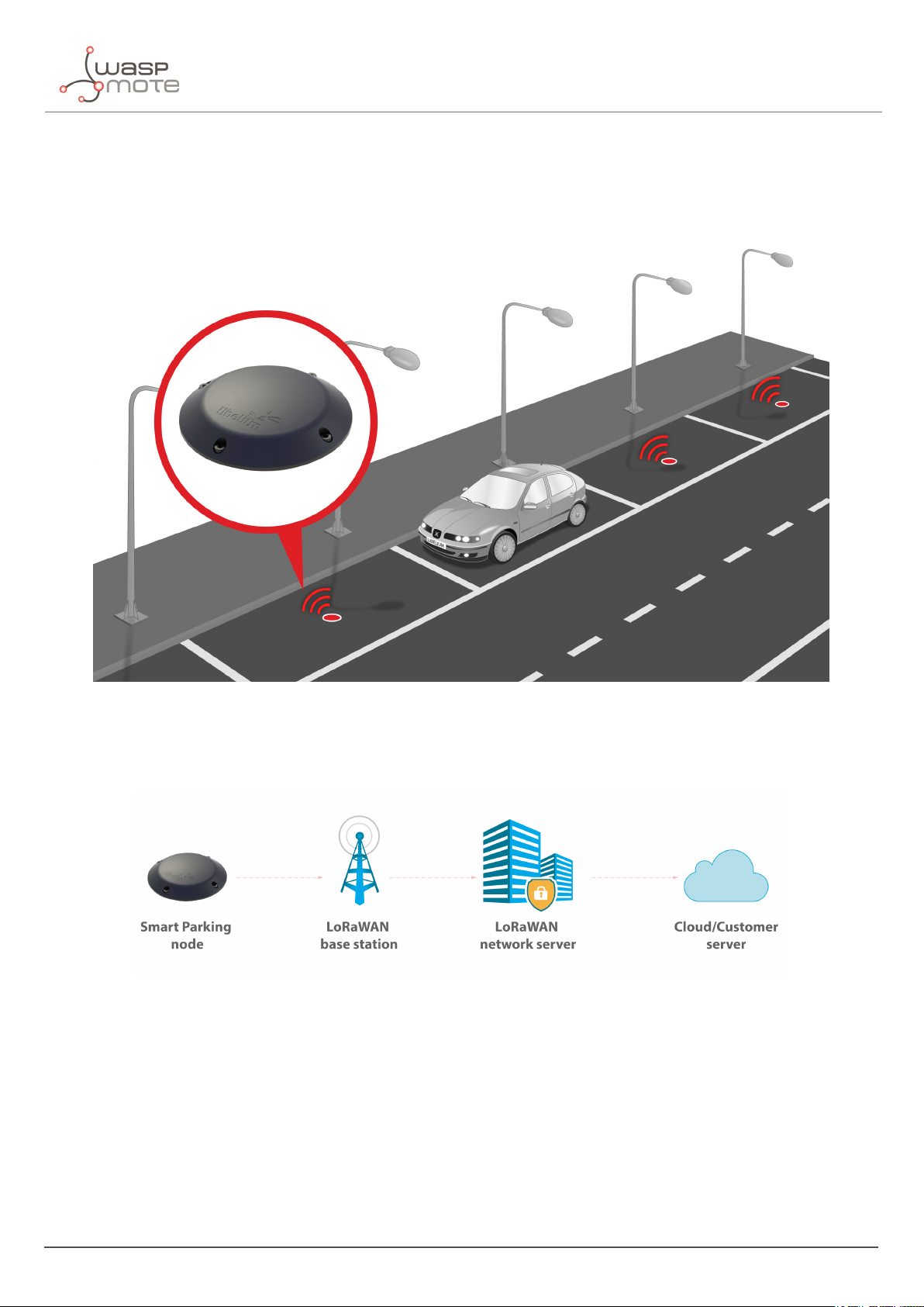
The Smart Parking v2 solution developed by Libelium allows citizens to detect available parking slots.
Introduction
Figure : Smart Parking node developed by Libelium
The node applies intelligent algorithms to detect changes in the state of the parking slot. Then data is transmitted
with the LoRaWAN radio to the final server.
Figure : Simplified Smart Parking network architecture
The nodes provisioning has been enormously improved. The nodes are delivered with default time settings and
also unique LoRaWAN identifiers and keys. So it is easy to use the default settings to register all nodes in the
LoRaWAN network server at a time.
The Smart Parking node improves the detection and stability performance thanks to a radar sensor which permits
to certainly know when objects are placed over the device. The next table shows a comparative analysis of the
current sensor technologies in the Smart Parking market:
- 6 - v7.5
Page 7
Introduction
Radar Infra-red Magnetometer
Reliability against nearby vehicle movement
Reliability against nearby parked vehicles
Reliability against electromagnetic interferences
Reliability in any lighting scenario
Stability during long-duration vehicle stays
Do not need an aperture in enclosure
Immunity against dirt or dust on enclosure
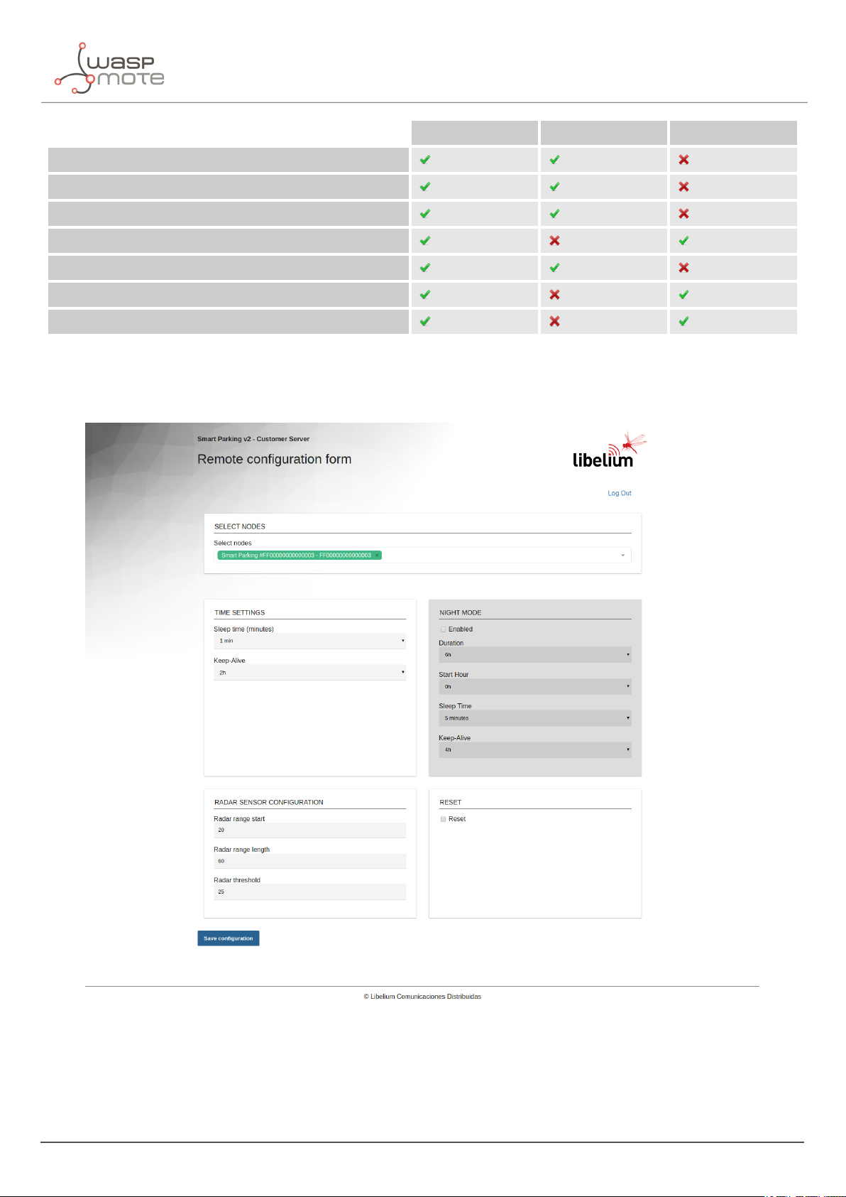
The node provides OTA-S (Over-The-Air Setup). This allows the user to remotely configure the node parameters
(sleep time, keep-alive, night-mode, etc) via the Remote Configuration Form. That makes it possible to directly
install the nodes with factory default settings and then update them from the server side.
Figure : Remote Configuration Form
- 6 - v7.5
Page 8

2. Network architecture
The network architecture of Smart Parking is based on the next elements:
‚
Smart Parking node
‚
LoRaWAN base station
‚
LoRaWAN Network Server
‚
Libelium Smart Parking Cloud Service or Customer Server
Network architecture
Figure : Smart Parking network architecture
- 7 - v7.5
Page 9
Network architecture
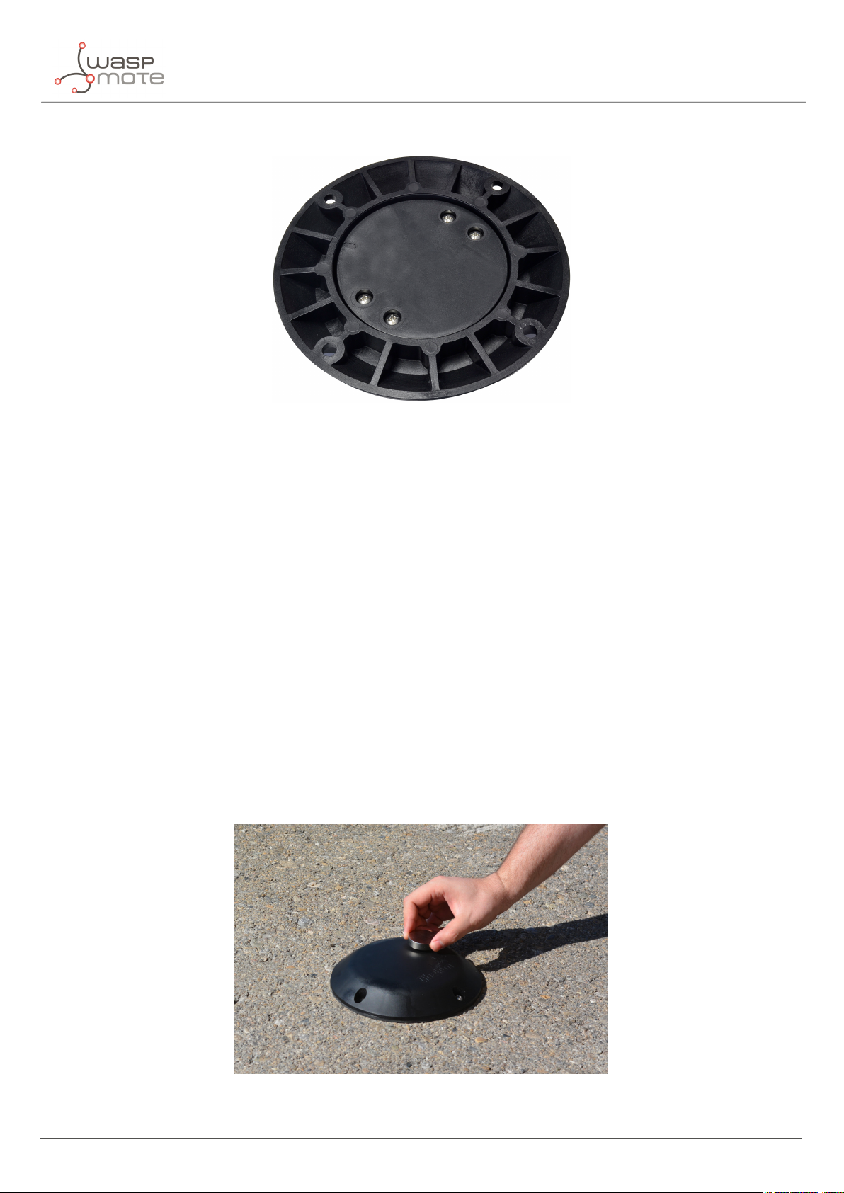
2.1. Smart Parking node
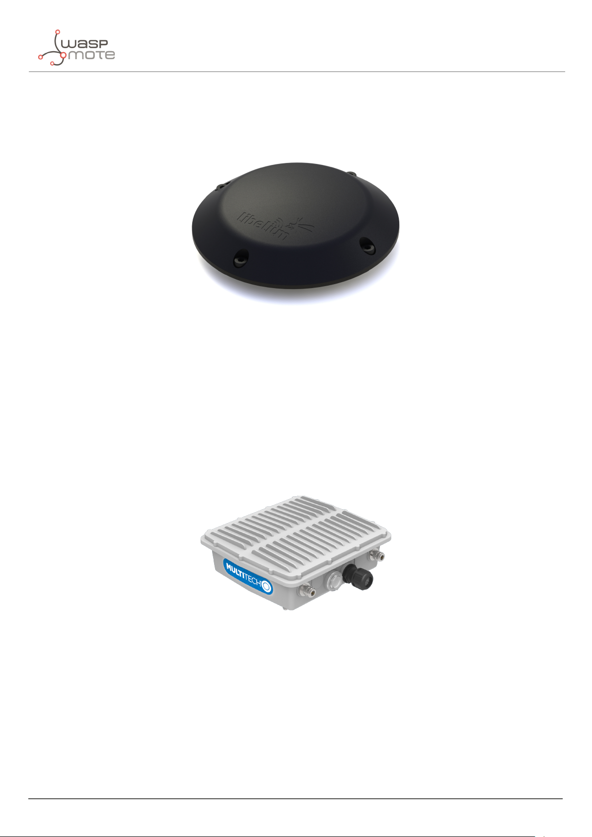
The Smart Parking node is the device installed in each parking slot. When the device detects a change of the parking
slot status (free/occupied), it sends a frame to the LoRaWAN base station.
Figure : Smart Parking node
2.2. LoRaWAN base station
The LoRaWAN base station (also known as gateway) must be installed in the surrounding area next to the parking
nodes. It receives data and forwards it to the LoRaWAN Network Server.
Libelium distributes base stations for LoRaWAN networks. All of them have LoRaWAN connection; some feature
Ethernet, WiFi or 4G connectivity too. Some base stations are ready to work outdoors (IP67 grade). Some of them
come pre-configured for certain LoRaWAN network servers (see next section). Also, some of them integrate an
embedded LoRaWAN Network Server.
Figure : LoRaWAN base station
2.3. LoRaWAN Network Server
The nodes registration must be done in the Network Server in order to receive LoRaWAN data from all nodes in
the network. Each node must be registered with an identifier and some encryption keys so the Network Server can
receive and decrypt the packets successfully.
The LoRaWAN Network Server purpose is to translate data from the LoRaWAN wireless network to an IP network.
Therefore, when Smart Parking nodes packets are received, a callback is performed in order to send data to the
- 8 - v7.5
Page 10

Network architecture
Libelium Smart Parking Cloud Service or to the Customer Server.
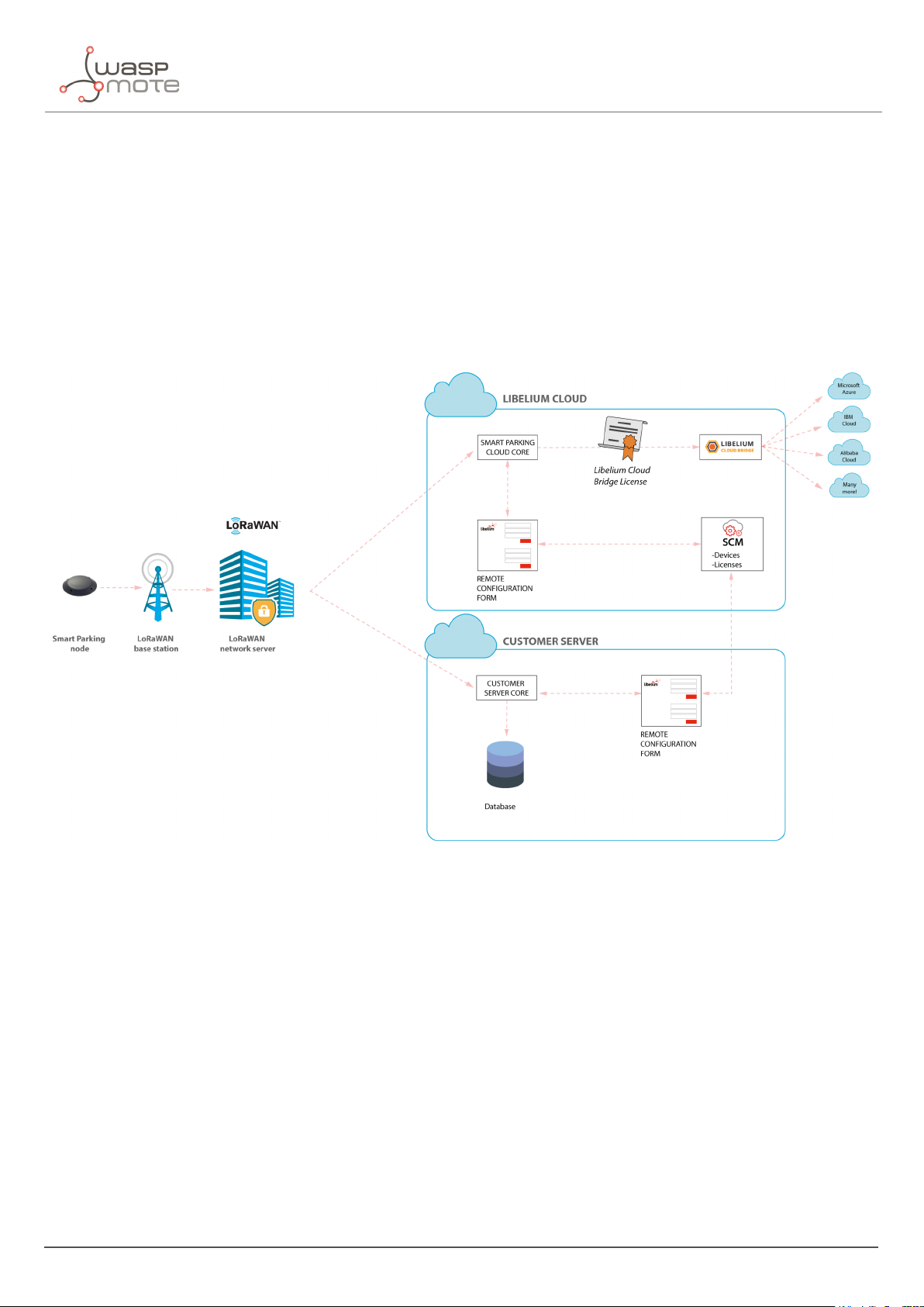
2.4. Libelium Smart Parking Cloud Service and Customer Server
The LoRaWAN Network Server connects to the final server, which can be the Libelium Smart Parking Cloud Service
or the Customer Server.
The LoRaWAN network servers currently supported are:
‚
Loriot
‚
Actility
‚
The Things Network
‚
The Things Industries
‚
The Embedded Network Server inside MultiTech base stations
If the customer wants to use a new LoRaWAN Network Server, then the Data Parser block must be modified in
order to receive data properly. Keep in mind that each Network Server implements its own HTTPS callback using a
different format.
The Remote Configuration Form allows the user to update the settings of each node (sleep time, keep-alive time,
night-mode, etc). The update is done remotely via LoRaWAN downlink radio packets.
The difference between the 2 types of server differ in the the possible client needs:
‚
The Customer Server is a software system provided by Libelium which permits to receive, decode and insert
data into a standard MySQL database. It is mandatory that the user sets up her own server to host the
Customer Server. Read the “
‚
The Smart Parking Cloud Service is a software service provided by Libelium which permits to receive,
Customer Server” chapter for further information.
decode and redirect the data to the final 3rd party IoT cloud (Amazon, Azure, etc). This retransmission is
done thanks to the cloud connectors running on another Libelium Cloud’s service: the Bridge. Read the
Libelium Smart Parking Cloud Service” chapter for further information.
“
- 9 - v7.5
Page 11
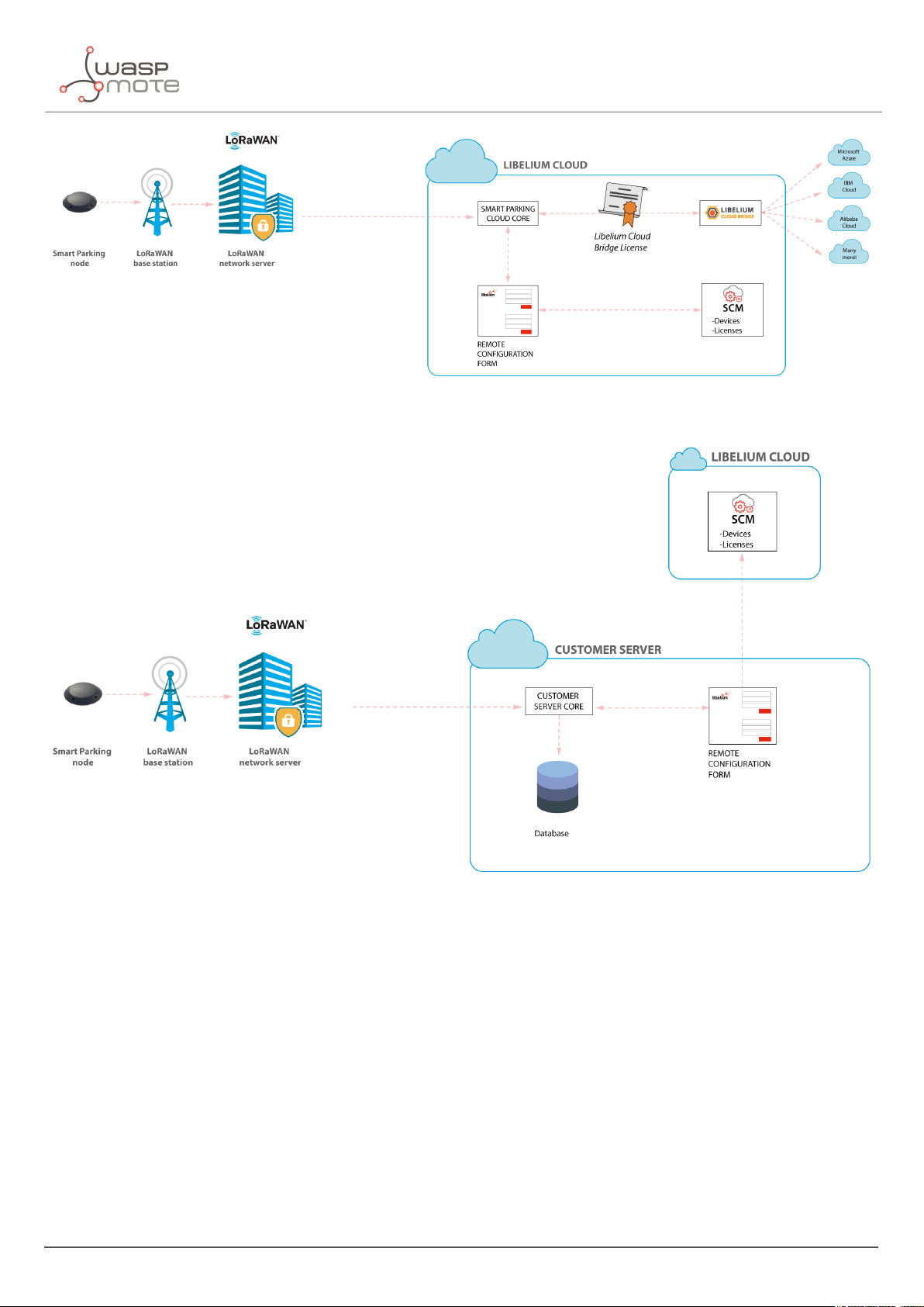
Figure : Libelium Smart Parking Cloud Service scenario
Network architecture
Figure : Customer Server scenario
- 10 - v7.5
Page 12
Smart Parking node
3. Smart Parking node
3.1. Hardware description
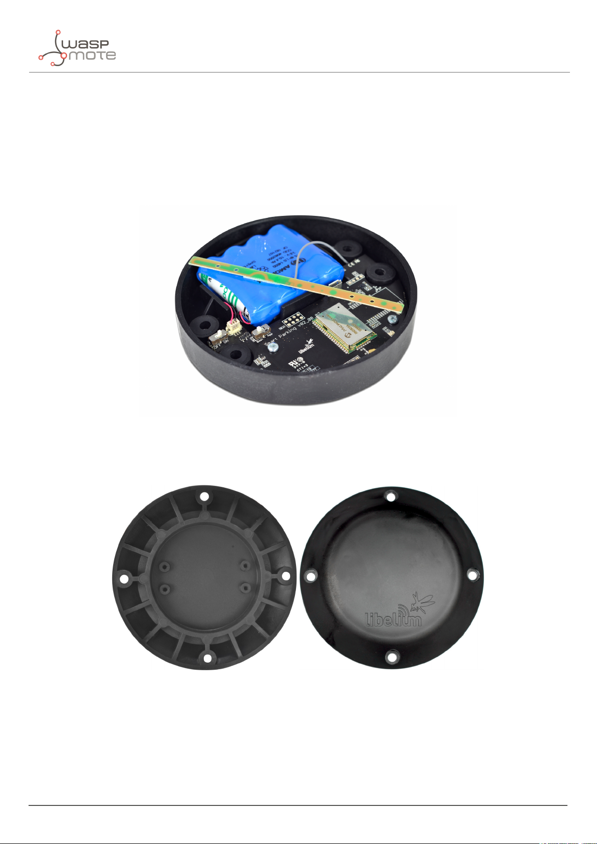
The Smart Parking node is based on 2 different pieces: the base and the external enclosure. The base of the Smart
Parking node includes the PCB, the battery, the antenna and the internal enclosure piece.
Figure : Base of a Smart Parking node
The base is screwed to the external enclosure piece:
Figure : External enclosure
- 11 - v7.5
Page 13
Smart Parking node
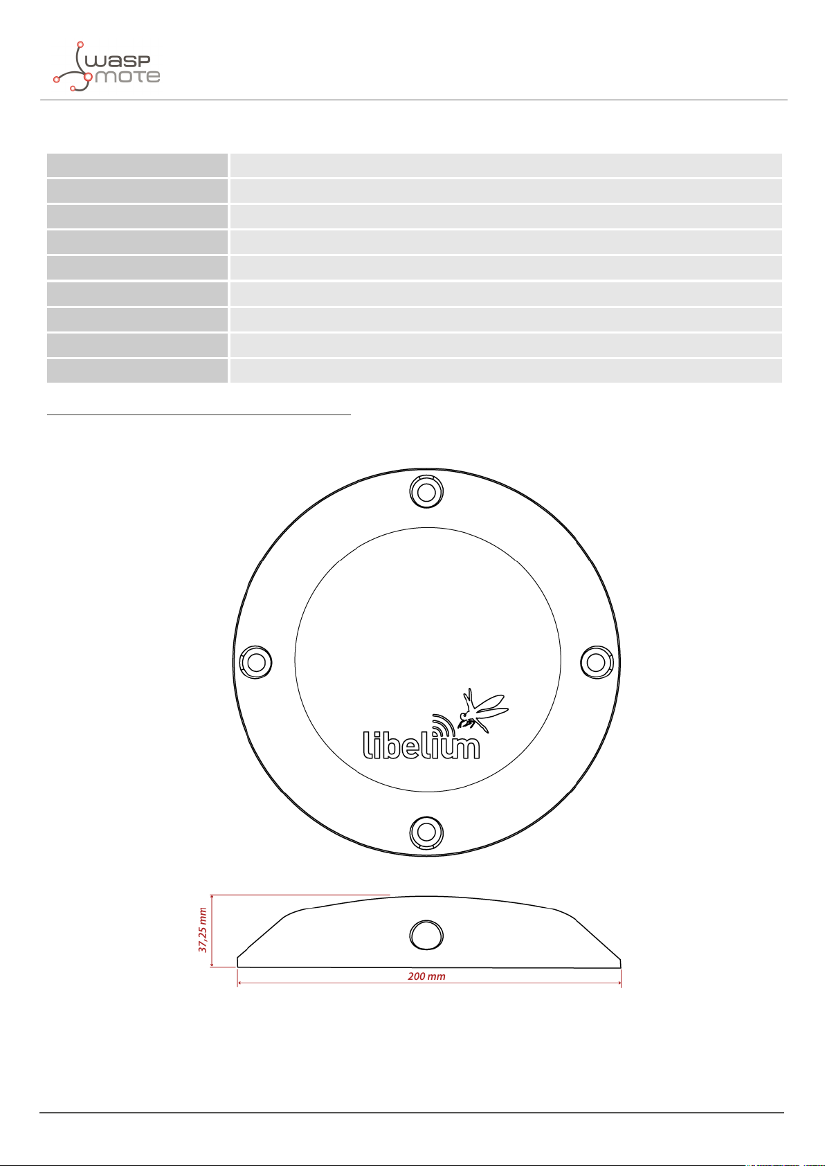
The next table shows the basic Smart Parking node characteristics.
Enclosure dimensions 37.25 mm x 200 mm
Power supply Built-in lithium-thionyl chloride (Li-SOCl2) batteries; expected lifetime of 4-10 years*
Configurable sleep time Min: 20 s / max: 10 min
Radio protocol LoRaWAN module
Dual detection Radar (main) and magnetic (backup)
Provisioning Ready to install (default LoRaWAN OTAA IDs and key are loaded to each node)
Node configuration Via "Remote Configuration Form" (web form)
LoRaWAN configuration Via "Smart Devices App" (Java desktop application)
Operating temperature -20 to +65 °C
(*) Under normal circumstances and depending on settings
Figure : Vaulted enclosure dimensions
- 12 - v7.5
Page 14
Smart Parking node
3.1.1. Node versions
Libelium provides the next versions of Smart Parking:
Reference Version Operating frequency
SP-EU Smart Parking EU 863.0 to 870.0 MHz (LoRaWAN EU863-870)
SP-US Smart Parking US 902.0 to 928.0 MHz (LoRaWAN US902-928)
SP-APLA-AU Smart Parking APAC / LATAM / AU / AU915 915.2 to 927.8 MHz (LoRaWAN AU915-928)
SP-IN Smart Parking IN 865.0 to 867.0 MHz (LoRaWAN IN865-867)
SP-APLA-AS Smart Parking APAC / LATAM / AU / AS923 923 MHz (LoRaWAN AS923)
3.1.2. LoRaWAN regions
The Smart Parking node supports the next LoRaWAN regions:
LoRaWAN region Supported by
EU 863-870 MHz ISM Band (Europe) Smart Parking EU
US 902-928 MHz ISM Band (United States) Smart Parking US
AU 915-928 MHz ISM Band (Australia) Smart Parking APAC / LATAM / AU / AU915
IN 865-867 MHz ISM Band (India) Smart Parking IN
AS 923 MHz ISM Band (Asia and ASEAN region) Smart Parking APAC / LATAM / AU / AS923
CN 779-787 MHz ISM Band (China) Not available
CN 470-510 MHz ISM Band (China) Not available
KR 920-923 MHz ISM Band (South Korea) Not available
433 MHz ISM Band (Worldwide) Not available
If you are interested in further information about LoRaWAN country regulations, please refer to the LoRa Alliance
regional parameters document.
3.1.3. LoRaWAN protocol and parameters
LoRaWAN is a Low Power Wide Area Network (LPWAN) protocol. It is a spread-spectrum modulation technique at
extremely low data-rates which permits sending data achieving long ranges.
The most important LoRaWAN parameters are:
‚
LoRaWAN EUI: Read-only, 8-byte, unique identifier which defines each LoRaWAN module in the market.
‚
Device EUI: Read/write, 8-byte identifier configured into the LoRaWAN module to be used as operating
identifier. By default, the "LoRaWAN EUI" of the module is factory-configured as "Device EUI" in the Smart
Parking node.
‚
Join mode: ABP or OTAA. Defines how the module joins the network. Different keys are needed for each
method.
‚
Device address: Needed for ABP. The 4-byte address of the the LoRaWAN module. Must be unique in its own
sub-network.
‚
Network Session Key: Needed for ABP. The 16-byte AES key. Used to generate Message Integrity Check.
‚
Application Session Key: Needed for ABP. The 16-byte AES key. Used to encrypt data.
‚
Application EUI: Needed for OTAA. The 8-byte application identifier. Needed for opening an OTAA session and
exchange encryption keys.
- 13 - v7.5
Page 15
Smart Parking node
‚
Application Key: Needed for OTAA. The 16-byte key. Needed for opening an OTAA session and exchange
encryption keys.
‚
Data-rate: Defines the transmission rate (bits per second). Each data-rate settings combines different
Spreading Factor (SF) and bandwidth (BW). By default, all LoRaWAN regions use the same data-rate (DR 0).
However, depending on the region, that means different SF and BW:
-
LoRaWAN EU863-870 version: SF12 / 125 kHz
-
LoRaWAN IN865-867 version: SF12 / 125 kHz
-
LoRaWAN AS923 version: SF12 / 125 kHz
-
LoRaWAN US902-928 version: SF10 / 125 kHz
-
LoRaWAN AU915-928 version: SF10 / 125 kHz
‚
ADR: Adaptive Data Rate setting which can be enabled or disabled. If ADR is enabled, the server will optimize
the data-rate based on the information collected from the network: the RSSI / SNR of the last received packets.
If you are interested in further information about LoRaWAN specifications, please refer to the LoRa Alliance
specifications document.
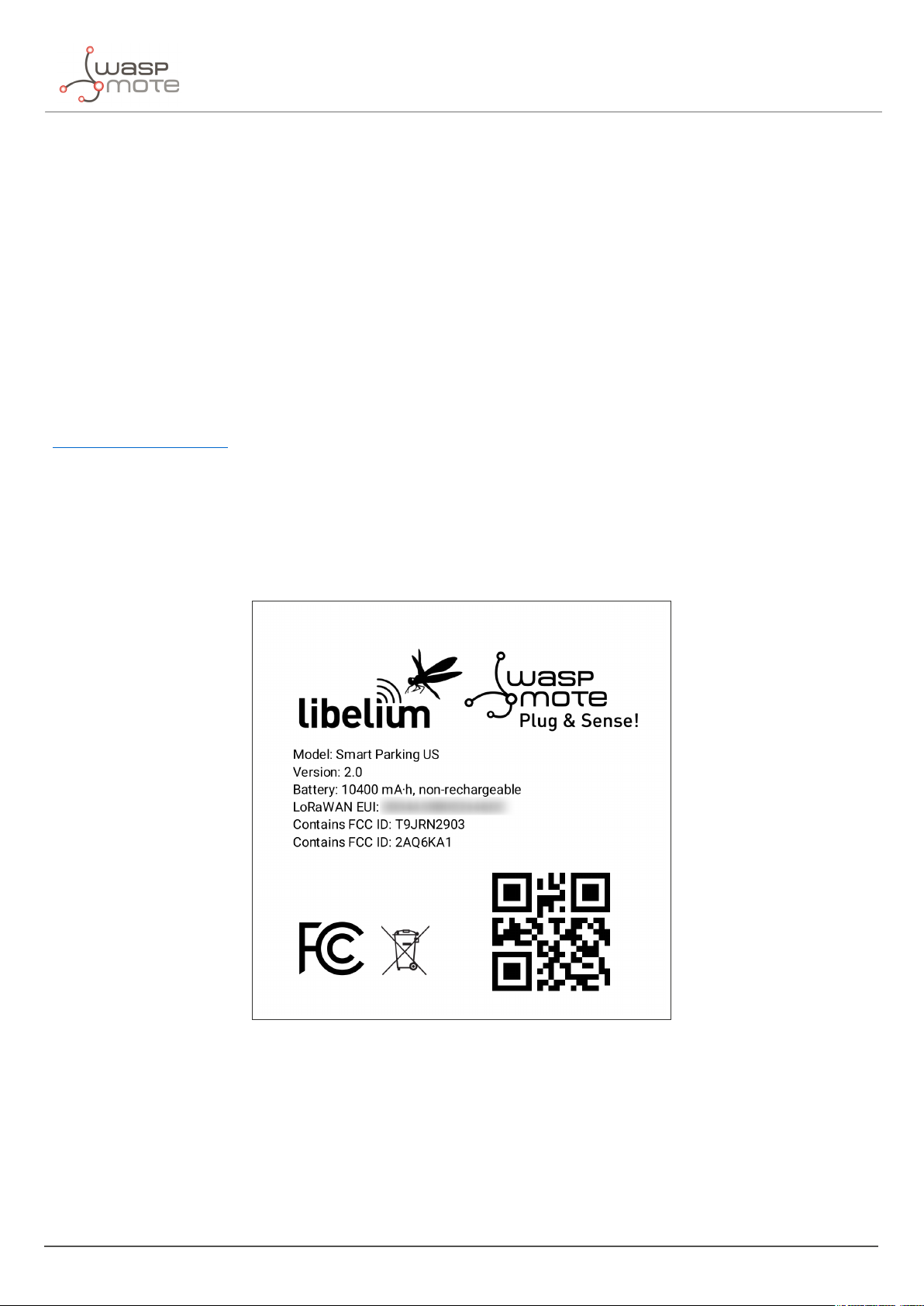
3.1.4. Identification label
There is a sticker on the bottom side of the Smart Parking node base. In this sticker, several device specifications
can be seen. For example the "Model" which refers to the device’s region. Also, the unique "LoRaWAN EUI" is
displayed so each node can be distinguished.
Figure : Smart Parking node label
3.2. Power and time consumption
The Smart Parking node firmware executes different steps since the node is started. Firstly, the node’s setup and
then an infinite loop where every cycle is based on measuring, sending if needed and sleeping. The next tables
show the power and time consumption of each step modelled as a pulse of a specific time duration and average
power consumption.
- 14 - v7.5
Page 16
Smart Parking node
3.2.1. Smart Parking EU
Power consumption Time consumption
Node setup 22.9 mA 59 s
Measure cycle 26 mA 340 ms
Measure and send cycle 17 mA 6 s
Sleep cycle 5.5 uA Depends on sleep time settings
(*) LoRaWAN EU is set to the default SF12 settings (worst case). The send process may be lower power if the node is close to the base station.
3.2.2. Smart Parking US
Power consumption Time consumption
Node setup 21.8 mA 53 s
Measure cycle 26 mA 340 ms
Measure and send cycle 20 mA 3.6 s
Sleep cycle 5.5 uA Depends on sleep time settings
(*) LoRaWAN US is set to the default SF10 settings (worst case). The send process may be lower power if the node is close to the base station.
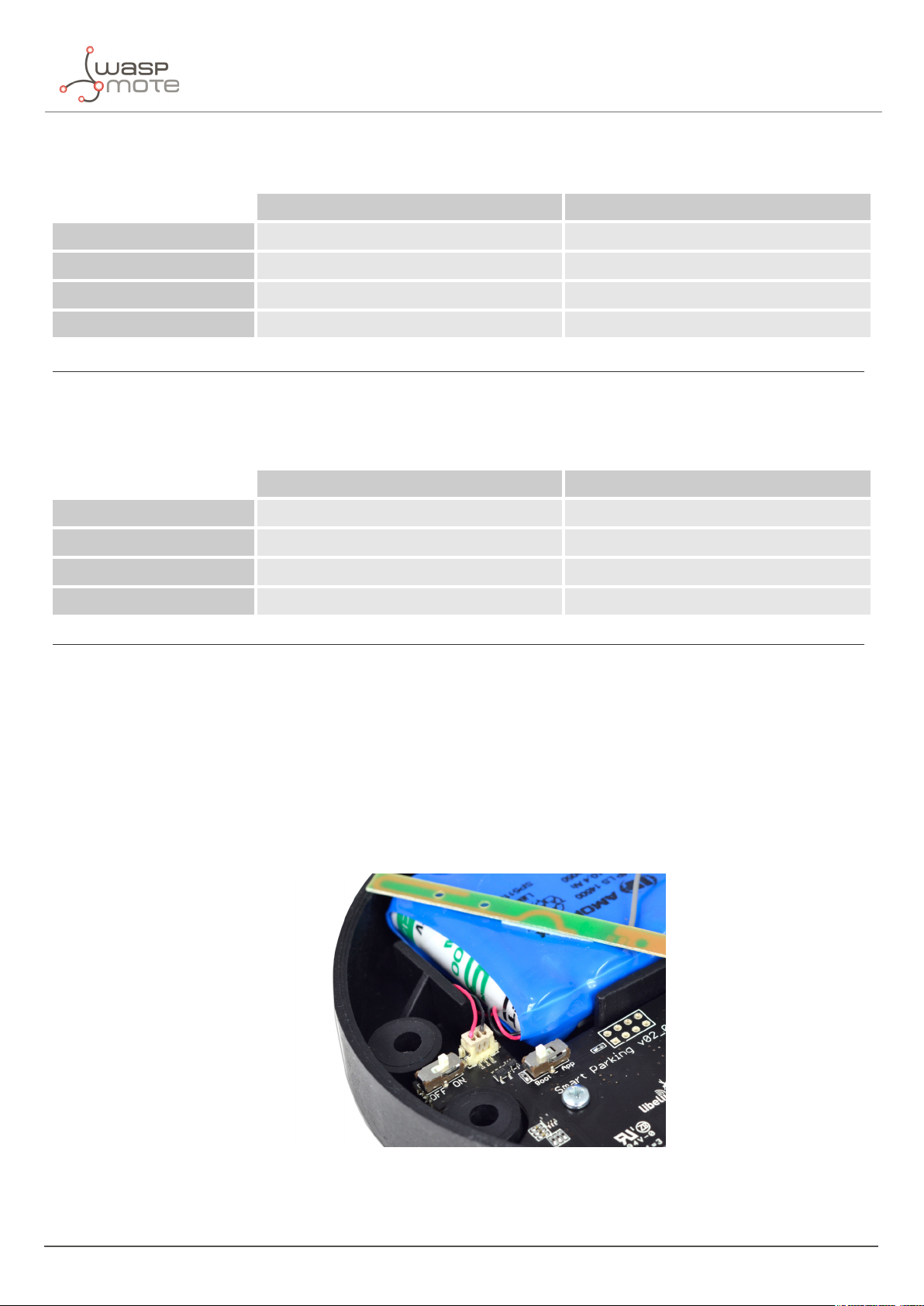
3.3. User switches
The Smart Parking node has 2 switches to manage the working mode:
‚
On/Off switch: Determines whether the node is powered-on or powered-off
‚
App/Boot switch: When the node is powered-on, this switch determines the performance state of the device
-
App position must be used for a normal operation mode, so the device executes the firmware within it
-
Boot position must be used for configuring purposes only
Figure : Smart Parking node "user switches"
When the node is powered-on (On switch), you can change from App to Boot or viceversa by changing the state
of the App/Boot switch. However, you must press the reset button to apply the operation mode change. Another
- 15 - v7.5
Page 17
Smart Parking node
possibility to successfully change the operation mode step-by-step would be to: power down the device (Off switch),
change the App/Boot switch, press the reset button and then power on the device.
Important:
Never leave the device set to On and Boot for more time than needed. The bootloader does not provide any sleep
mode and it will waste the battery of the device. So when you finish reconfiguring the device, please set the node
in off state.
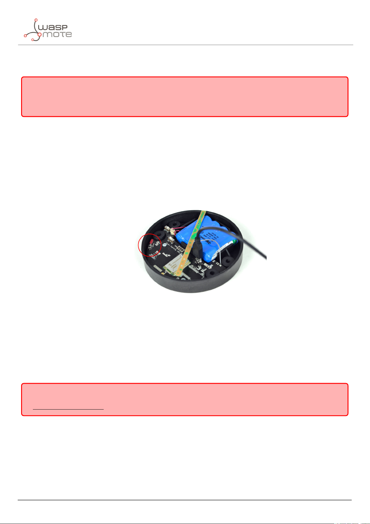
3.4. Reset button
The reset button can be used to re-start the node in the corresponding operation mode (App or Boot). If the node
is set up to "App" (normal operation mode), pressing the reset button will re-start the program execution. On the
other hand, if the node is set up to Boot (configuration mode), pressing the reset button will re-start the MCU
bootloader for reconfiguration or firmware update.
Figure : Reset button
3.5. Node setup
3.5.1. "Ready to install" state
Important:
Libelium provides the nodes "ready to install" so the user only needs to install the nodes and follow the
"Magnet start-up" process”.
“
The Smart Parking node has a power-on process in order to put the device into a "ready-to-install" state:
‚
Step 1: The switches are set to "App" and "Off" (press the reset button to make sure you discharge capacitors)
‚
Step 2: You power the device on by sliding the switch from "Off" to "On"
‚
Step 3: Both LEDs (red and green) blink rapidly for 5 times
‚
Step 4: Red LED blinks once for 1 second to indicate that the device enters sleep mode for the 1st time. Now
the node is in a "ready to install" state. The customer should install the node on the real scenario and perform
the "Magnet start-up" process.
- 16 - v7.5
Page 18
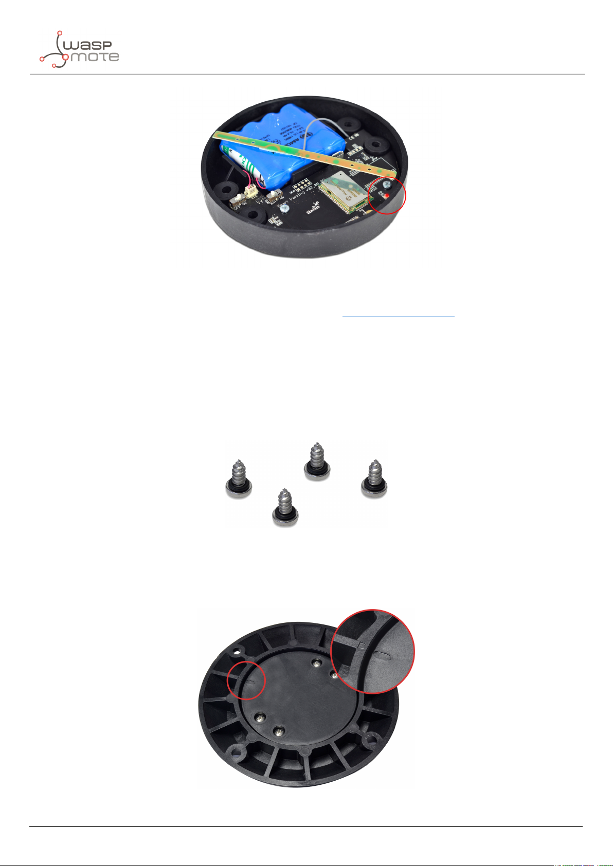
Figure : The red LED blinks once to indicate ready-to-install state
You can see how the previous steps are performed in this video: Ready to install process
Smart Parking node
3.5.2. How to close the Smart Parking node
After following the previous steps, the device can be closed. In order to close the node correctly and ensure correct
sealing, the following steps must be strictly followed.
‚
Step 1: Make sure that the screws have the o-rings to prevent water ingress.
Figure : Screws with o-ring
‚
Step 2: Ensure that the top surface of the gasket is clean and contains no foreign objects.
‚
Step 3: Place the inner casing inside the outer casing and make sure that the 2 position marks match.
Figure : Enclosure position marks
- 17 - v7.5
Page 19
Smart Parking node
‚
Step 4: Insert the screws and tighten them halfway.
Figure : Screws in their position
‚
Step 5: Finally, tighten the 4 screws firmly. Do not use the maximum pressure (do not go all the way with the
screws), because the o-rings could be ejected from the screws, and then the waterproof feature would NOT
be valid. Besides, do not screw too hard and keep on screwing, because the screws could carve the female
sockets, expanding their inner diameter; this would cancel the waterproof quality too.
Libelium manufactures and provides all nodes configured after following all explained steps, so the node is "ready
to install". By factory default, all nodes are configured with their unique LoRaWAN EUI and random private keys.
On the other hand, if different LoRaWAN parameters are desired, “
Smart Devices App” must be used to change the
settings and repeat the previously explained steps.
3.5.3. "Magnet start-up" process
Once the node has been set to "ready to install" state and it has been closed and placed on the parking slot, the
"magnet start-up" must be done. This process consists on resetting the device using the magnet for 3 consecutive
times. Each magnet reset must be separated by at least one second period.
The best way to proceed with the magnet is to go over the enclosure from left to right in a one-motion movement.
Then wait for at least one second (although you can wait more) and proceed again until you complete 3 magnet
resets.
Figure : Magnet reset
- 18 - v7.5
Page 20

Smart Parking node
In the next video-clip you can see how the "magnet start-up" is performed: Magnet start-up
After finishing the "magnet start-up", the node starts working normally for the rest of the time. No more three-time
"magnet resets" are needed in order to reset the device properly. So if a 4th magnet reset or software reset is
applied, the device will reset and continue working normally again.
Important:
The "magnet start-up" is only mandatory when the node is powered from a power-off state. In other words, when
the device is set to a "ready to install" state.
3.6. How the node works
3.6.1. Frame types
The Smart Parking architecture manages different uplink and downlink frames.
The next table shows the Uplink frames:
Frame type #num Description
Start frame 1 4 First frame sent by the node when starting (with params settings)
Start frame 2 5 Second frame sent by the node when starting (with params settings)
Info frame 0 Used to inform a Parking Status change
Keep-alive frame 1 Used to inform the device keeps working since last reported status
Configuration uplink 2 Used to confirm a "Configuration downlink" was applied or not
RTC update request 7 Used to request for an RTC sync once every day
The next table shows the Downlink frames:
Frame type #num Description
Used to update the node parameters. After the customer sets up a new
Configuration downlink 3
RTC sync frame 6
The uplink frames are 11-byte long to always comply with the LoRaWAN datarate worst case scenario. Their
structure consists on 2 parts: header and payload. The "header" format is always the same for all uplink frame
types. On the other hand, the "payload" format may be different for each frame type.
node configuration in the Remote Configuration Form a new "Configuration
downlink" frame is enqueued into the LoRaWAN network server’s downlink
queue.
Used to sync the node’s RTC to the server’s timestamp. It is the mandatory
response to "Start frame 1" and "RTC update request" uplink frames.
Header Payload
2 bytes 9 bytes
Regarding the downlink frames, they have variable length and its format is private to the customer. The "RTC sync
frame" is the mandatory response for both "Start Frame 1" and "RTC update request" frames. The "RTC sync frame"
provides the server time to the nodes in order to keep the RTC updated. Also, the "Configuration downlink" is an
asynchronous frame sent by the server when the Remote Configuration Form is managed by the customer.
You must keep in mind that when a downlink packet is requested there are usually some issues related to LoRaWAN
- 19 - v7.5
Page 21

Smart Parking node
network latency. This implies that the 1st request attempt usually fails. In that case, a 2nd attempt is sent in order
to retrieve the lost downlink packet. For this reason, you might see that a couple of "Start Frame 1" or "RTC update
request" frames are sent sequentially during the execution of the program.
3.6.2. Frame header
The "Header" included in each uplink frame contains 2 bytes:
Byte Bit Field
0 7 Parking lot status
0 6 Battery state
0 5 Configuration uplink acknowledgement
0 4 Sensor recalibration
0 3-0 Frame type
1 7-0 Sequence number
The meaning of each field is:
‚
Parking slot status:
-
0: Free
-
1: Occupied
‚
Battery status:
-
0: OK
-
1: Warning. The battery level measured is below the warning threshold (3340 mV)
‚
Configuration uplink frame acknowledgement status:
-
0: ACK
-
1: NACK
‚
Sensor recalibration:
-
0: No calibration was done since the last uplink
-
1: At least one calibration was done since the last uplink
‚
Frame type: Number related to frame type
-
0: Info frame
-
1: Keep-alive frame
-
2: Configuration uplink frame
-
3: Configuration downlink
-
4: Start frame 1
-
5: Start frame 2
-
6: RTC sync frame
-
7: RTC update request
‚
Sequence number: This is a 1-byte field so the sequence number goes from 0 to 255. When 255 is reached,
the counter starts from zero again.
3.6.3. Frame payload
The "Payload" contents vary depending on each frame type.
- 20 - v7.5
Page 22

The Start frame 1 frame contents are:
‚
Header ("Parking slot status" does not provide valid data)
‚
Firmware version:
-
From 1 to 8: Not released firmware versions
-
9: v1.0.0
-
10: v1.0.1
-
11: v1.0.2
-
13: v1.0.4
-
14: v1.0.5
-
16: v1.0.6 (last stable version)
‚
Battery level
‚
Radar settings (threshold and range)
‚
LoRaWAN settings (join mode and ADR)
The Start frame 2 frame contents are:
‚
Header ("Parking slot status" does not provide valid data)
‚
Sleep and Keep-alive time settings
‚
Night-mode settings (enabled/disabled, start hour, duration, sleep time)
Smart Parking node
The Info frame contents are:
‚
Header
‚
Sensor error
‚
Temperature
‚
Timestamp (hour and minutes)
‚
Radar measurement (Distance, amplitude and number of reflections)
The Keep-alive frame contents are:
‚
Header
‚
Sensor error
‚
Temperature
‚
Timestamp (hour and minutes)
‚
Radar measurement (Distance, amplitude)
‚
Battery level
The RTC update request frame contents are the same as Keep-alive frame.
Important:
The Customer Server provides the needed source code to parse this data into a more comprehensive structure. The
Libelium Cloud Bridge also provides the needed tools to transmit the parsed data to a 3rd party IoT cloud. For
more information, please refer to the “
Customer Server” section.
- 21 - v7.5
Page 23
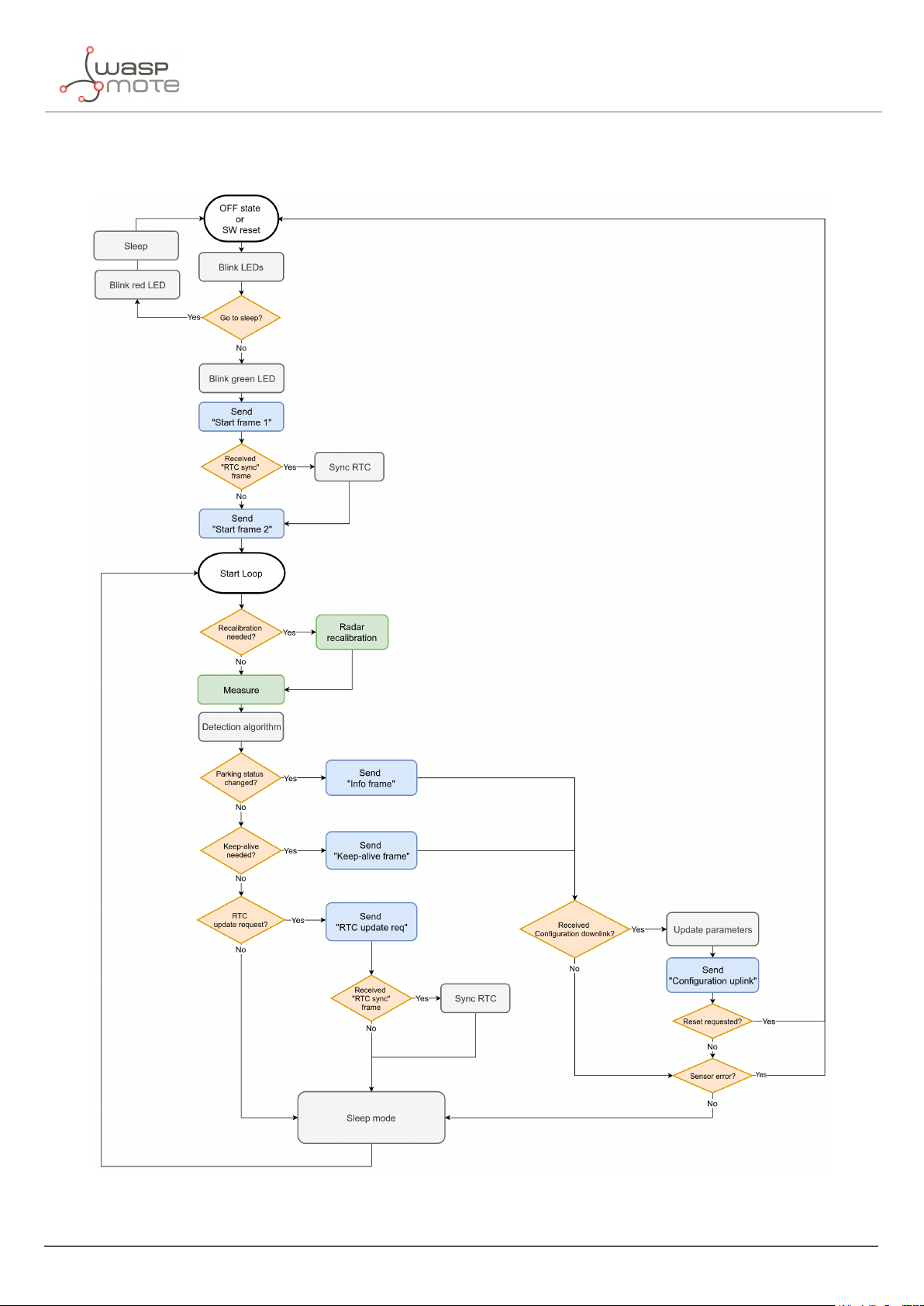
3.6.4. Node program flowchart
Smart Parking node
Figure : Smart Parking node program flowchart
- 22 - v7.5
Page 24
Smart Parking node
3.7. Node parameters
3.7.1. Parameters description and ranges
The Smart Parking node has different parameters that change the timing and detection performance of the node.
The next table shows the node parameters:
Parameter Range Description
Sleep time 1-10 min or 20-59 s Minutes or seconds elapsed between each measurement cycle
Keep-alive time 0.5, 1, 2,..., 23 hour
Night-mode 0 or 1 Night-mode disabled/enabled
Night-mode start 0, 1,..., 23 hour Night-mode starts when RTC reaches this parameter field
Night-mode duration 1, 2,..., 15 hour Night-mode period is equal to this field
Night-mode sleep 1, 2,..., 10 min Sleep time applied during night-mode
Radar range start 20 to 50 cm
Radar range length 50 to 100 cm Range of measurement to be added to "range start" value
Radar threshold 5 to 100
LoRaWAN join mode 0 (ABP) or 1 (OTAA) Join mode used by the LoRaWAN radio module
LoRaWAN DevEUI 8-byte identifier Defines the device EUI used by the LoRaWAN radio
LoRaWAN DevAddr 4-byte identifier
LoRaWAN NwkSKey 16-byte key
LoRaWAN AppSKey 16-byte key
Hours elapsed since last uplink message which triggers a new
Keep-alive frame
Starting measurement distance (objects below this value are not
detected)
Threshold used in detection algorithm, so higher threshold imply
less sensitive detection
Defines the device address used by the LoRaWAN radio in ABP
mode
Defines the LoRaWAN Network Session Key used by the LoRaWAN
radio in ABP mode
Defines the LoRaWAN Application Session Key used by the
LoRaWAN radio in ABP mode
LoRaWAN AppKey 16-byte key
LoRaWAN AppEUI 8-byte identifier
LoRaWAN port 1 to 223 Defines the port used for uplink sendings
LoRaWAN ADR 0 (off) or 1 (on) Defines if Adaptive Data Rate is enabled or disabled
LoRaWAN RX1 Delay 0 to 65536 Defines the delay after first LoRaWAN rx window
LoRaWAN Subband 8-bit bitmap
Important:
The LoRaWAN identifiers and keys must be registered in the LoRaWAN network server before starting the node in
order to receive data. For OTAA mode: DevEUI, AppEUI and Appkey. For ABP mode: DevEUI, DevAddr, NwkSKey and
AppSKey.
Defines the LoRaWAN Application Key used by the LoRaWAN radio
in OTAA mode
Defines the LoRaWAN Application EUI used by the LoRaWAN radio
in OTAA mode
Defines the sub-band used by the LoRaWAN radio (only applies to
US and AU versions)
- 23 - v7.5
Page 25
Smart Parking node
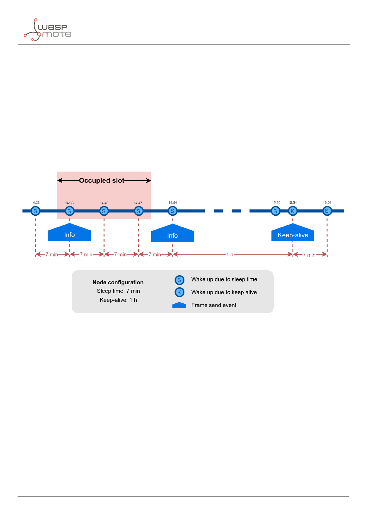
3.7.2. Understanding Info and Keep-alive frames
In the regular working mode (day-mode), "Sleep" and "Keep-alive" parameters are used. So the node normally
sleeps for a specific "Sleep" time then wakes-up, measures and applies the algorithm detection in order to detect
changes in the parking slot.
If a change is detected from ’free’ to ’occupied’ or viceversa, then an "Info" frame is sent. If no change occurred
during the last "Keep-alive" time, then a Keep-alive frame is sent. Besides, if a sensor error is detected, a Keep-alive
frame sending is forced in order to inform about this issue.
Example parameters used:
‚
Sleep: 7 minutes
‚
Keep-alive: 1 hour
Figure : Example Info and Keep-alive frames
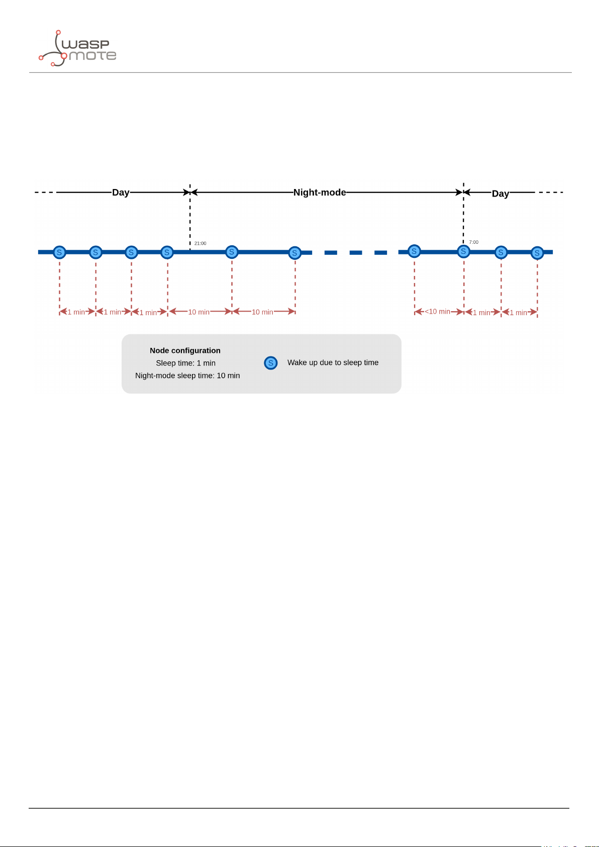
3.7.3. Understanding night-mode
As shown in the parameters table, there are some parameters that allow the user to configure the node to use 2
working modes depending on time settings: day-mode and night-mode.
The night-mode is a secondary and optional working mode that allows the user to configure a different time basis
parameters in order to reduce the battery impact. So, it was developed to use it when the parking slot is expected
to have fewer changes (i.e. at night). Therefore, a different night-mode "Sleep" setting is used.
It is not mandatory to use the night-mode during night. This mode is thought to be used when less vehicle
movement is expected in the parking slots. Which could be during day time.
Example:
‚
Day-mode:
-
Sleep: 1 minute
‚
Night-mode:
-
Night-mode start hour: 21 hours (9 PM)
- 24 - v7.5
Page 26
Smart Parking node
-
Night-mode duration: 10 hours (Night-mode goes from 9 PM to 7 AM)
-
Night-mode sleep time: 10 minutes
In the example, from 9 PM to 7 AM, the node will waste less battery because measurements are done every 10
minutes instead every minute. Keep-alive events are not shown but a Keep-alive event would be triggered if no
change occurs in the parking slot.
Figure : Example of day and night mode
The conclusion is that the Night-mode is interesting for customers who certainly know the parking slot is expected
to have fewer changes during large periods of time every day.
Note: From October 2019 the "keep-alive night-mode" setting was deprecated to simplify the parameter
management. Since then, there is a single keep-alive setting, for both "normal mode" and "night mode".
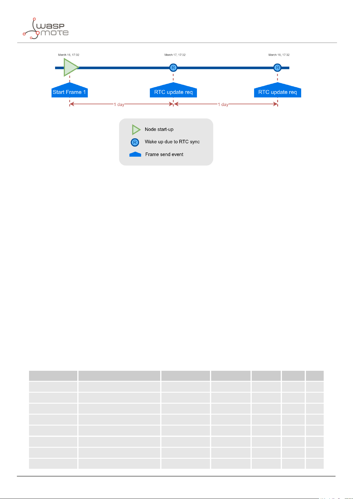
3.7.4. Understanding RTC synchronization
There are specific frame types that allow the node to synchronize the RTC to the server timestamp.
The "Start Frame 1" expects an answer from the server with the timestamp (hours and minutes). This frame is sent
after starting the node or a software reset.
Besides, the node’s firmware provides a mechanism which an "RTC update request" frame is sent every 24 hours
since the node was started or reset. This frame waits for a downlink frame which brings the current server
timestamp (hour and minutes).
- 25 - v7.5
Page 27
Smart Parking node
Figure : Example of RTC sync
Note: The RTC sync is important for Night-mode only where it mandatory to operate with a correct timestamp in
order to enter and exit from night-mode to day-mode and viceversa.
3.7.5. Understanding uplink frames format (real example)
The next table shows all frames sent by a single node since it was started. The different columns display the parsed
data from the received "uplink data".
Example:
‚
Day-mode:
-
Sleep: 1 minute
-
Keep-alive: 2 hour
‚
Night-mode:
-
Night-mode start hour: 22 hours (10 PM)
-
Night-mode duration: 8 hours (Night-mode goes from 10 PM to 6 AM)
-
Night-mode sleep time: 5 minutes
It is possible to distinguish the starting frames at the beginning of the execution. Then the node informs with a new
Keep-alive every 2 hours. Any change of Parking slot status implies a new Info frame. And after 24 hours working,
you can see the RTC request performed by the node.
Timestamp Uplink data F. Type Parking lot Battery Recal Seq
04/15/19 15:59 040009c419143c01000000 4 (Start 1) NULL 0 0 0
04/15/19 15:59 0501010000011608050200 5 (Start 2) NULL 0 0 1
04/15/19 15:59 110200170f3b00000000b0 1 (Keep-alive) 0 0 1 2
04/15/19 17:29 01030013101d00000000c8 1 (Keep-alive) 0 0 0 3
04/15/19 19:29 1104000d131d00000000d4 1 (Keep-alive) 0 0 1 4
04/15/19 21:29 0105000a151d00000000d4 1 (Keep-alive) 0 0 0 5
04/16/19 23:29 0106000a173b00000000d5 1 (Keep-alive) 0 0 0 6
04/16/19 01:29 01070009040000000000d4 1 (Keep-alive) 0 0 0 7
- 26 - v7.5
Page 28
Smart Parking node
04/16/19 03:29 01080008060000000000d5 1 (Keep-alive) 0 0 0 8
04/16/19 05:29 01090008060000000000d5 1 (Keep-alive) 0 0 0 9
04/16/19 06:04 800a000906040172410005 0 (Info) 1 0 0 10
04/16/19 08:04 810b000a0804016d4268d4 1 (Keep-alive) 1 0 0 11
04/16/19 10:04 810c000b0a04017b3e00d4 1 (Keep-alive) 1 0 0 12
04/16/19 12:04 810d000c0c04016d3e58d4 1 (Keep-alive) 1 0 0 13
04/16/19 14:05 810e000e0e05016f3e80d4 1 (Keep-alive) 1 0 0 14
04/16/19 15:58 870f000f0f3b016b3dd0d4 7 (RTC request) 1 0 0 15
04/16/19 15:59 8710000f0f3b016b3dd0d4 7 (RTC request) 1 0 0 16
04/16/19 17:59 8111000f101c016e3c98c7 1 (Keep-alive) 1 0 0 17
04/16/19 18:32 002a000f101f0000000000 0 (Info) 0 0 0 18
04/16/19 20:02 012b0010110100000000c7 1 (Keep-alive) 0 0 0 19
04/16/19 22:32 012c0011111f00000000c8 1 (Keep-alive) 0 0 0 20
04/17/19 00:02 012d0010120100000000c7 1 (Keep-alive) 0 0 0 21
3.7.6. Factory default values
Libelium provides all Smart Parking nodes with factory default parameters.
Parameter Default value
Sleep time 1 min
Keep-alive time 2 hour
Night-mode 0 (disabled)
Night-mode start 0 hour
Night-mode duration 6 hour
Night-mode sleep 5 min
Radar range start 20 cm (should not be changed)
Radar range length 60 cm (should not be changed)
Radar threshold 25 (should not be changed)
LoRaWAN join mode 1 (OTAA)
LoRaWAN DevEUI unique factory default value
LoRaWAN DevAddr unique factory default value
LoRaWAN NwkSKey unique factory default value
LoRaWAN AppSKey unique factory default value
LoRaWAN AppKey unique factory default value
LoRaWAN AppEUI unique factory default value
LoRaWAN port 3
LoRaWAN ADR 0 (off)
- 27 - v7.5
Page 29

Smart Parking node
LoRaWAN RX1 Delay 1000 (should not be changed)
LoRaWAN Subband 8-bit bitmap
3.7.7. Configure new parameter values
The Smart Devices App and the Remote Configuration Form allow the user to configure new parameters to the
node. The 1st one is a desktop Java application which implies opening the node enclosure and plug a micro-USB
cable to the node. The 2nd one is a form allocated in the Libelium Smart Parking Cloud Service or in the Customer
Server, which permits to remotely change some of the node parameters.
Regarding the time and sensor parameters, the same values are set to all nodes manufactured by Libelium. The
default values can be seen in the previous section. However, the customer can configure the time and sensor
settings using both Smart Devices App and Remote Configuration Form.
Regarding the LoRaWAN parameters, all keys are randomly generated for each node and kept secret. The DevEUI
set to the node is the LoRaWAN hardcoded EUI which is unique for each radio chipset. However, the client can
configure/modify all LoRaWAN parameters using the Smart Devices App only (the Remote Configuration Form does
not permit it).
Note: For further information about this matter please refer to the “
Remote Configuration Form” sections.
“
Smart Devices App” and
- 28 - v7.5
Page 30
Libelium Cloud management
4. Libelium Cloud management
4.1. Introduction to the Libelium Services Cloud Manager SCM
According to the Smart Parking network architecture, users can select between 2 ways of working with the Smart
Parking nodes: one using the Customer Server, and the other using the Smart Parking Cloud Service. Regardless of
the solution chosen, users will always need to operate with the Services Cloud Manager (SCM), which is the basis
of the Libelium Cloud.
Figure : Smart Parking network architecture
- 29 - v7.5
Page 31

Libelium Cloud management
4.2. SCM account
This is the 1st step users must follow. Anyone can create a new account in the SCM for free. This account will
allow you to manage your Libelium devices and also all your licenses and services. You can access the SCM at
https://cloud.libelium.com.
Figure : SCM Home page
4.2.1. Creating an account
To register and set up a password, go to https://cloud.libelium.com/register and click on “Create account”.
Figure : "Create account" button
Complete the information in the form (all the fields are mandatory):
‚
Name: Your name
‚
E-mail address: A valid e-mail address, it will be used for verification purposes
‚
Password and Confirm password: Set your password
Accepting Terms & Conditions is also mandatory to create a new account in the SCM.
- 30 - v7.5
Page 32

Libelium Cloud management
Figure : Create account form
4.2.2. Signing in
To sign in the SCM, go here and click on the “Sign In” button.
Figure : "Sign-in" button
Complete the information in the form. The e-mail and password used when creating the account will be required:
‚
E-mail address: E-mail address used for registration
‚
Password: Password used for registration
- 31 - v7.5
Page 33

Figure : Sign-in form
Libelium Cloud management
The Terms & Conditions accepted when creating the account apply for any time you sign in the SCM. If you do not
have an account yet, follow the steps described on the section “Create an account” to obtain valid credentials. If
you already created an account and need a password reminder, you can click on “Forgot password?”.
4.3. Smart Parking nodes registration
After placing an order including Smart Parking nodes you should receive an e-mail with the activation codes for all
your devices. In this e-mail you will directly find clickable links to register the devices in the SCM. You can register
your nodes one by one if needed, but it’s faster to register all of them at once with the global Activation Code.
- 32 - v7.5
Page 34

Libelium Cloud management
Figure : Activation codes e-mail
By clicking on these links you will be able to complete the registration process by following the wizard:
Figure : Step1. Enter device activation code
Figure : Step2. Confirm activation
4.4. Editing Smart Parking nodes
You can change the "name", "project", "description" and (if the device is a Smart Parking node) the "LoRaWAN EUI"
of the device by clicking the pencil icon located next to the each device. Finally you must save the changes.
- 33 - v7.5
Page 35

Libelium Cloud management
Figure : Edit a device
4.5. Export CSV file with nodes credentials
The SCM allows the user to export all nodes credentials via HTTPS secure connection. The exported file is a CSV
file with all credentials needed for OTAA join mode. The exported LoRaWAN credentials are the same as they were
configured by factory default. This means that if the user changed the LoRaWAN credentials via "Smart Devices
App", then the exported credentials will not be same.
In order to export the file, you must go to
website you will identify the "Smart Parking actions" button which permits to download the nodes credentials by
clicking on the "Download nodes keys" button.
https://cloud.libelium.com, log in and then access "My Devices". On the
Figure : Export CSV file with all nodes credentials
The CSV file for ’N’ devices exported from the SCM follows the next format:
- 34 - v7.5
Page 36

<DevEUI_1>,<Serial>,<AppEUI_1>,<AppKey_1>
<DevEUI_2>,<Serial>,<AppEUI_2>,<AppKey_2>
<DevEUI_3>,<Serial>,<AppEUI_3>,<AppKey_3>
...
<DevEUI_N>,<Serial>,<AppEUI_N>,<AppKey_N>
Libelium Cloud management
- 35 - v7.5
Page 37

Smart Devices App
5. Smart Devices App
Libelium Smart Devices App is an software tool developed by Libelium that allows users install new firmware
versions and program the configuration of the new Libelium devices in a few clicks. At the moment it is only
available for Smart Parking and MySignals products, but the list will be incremented shortly.
Figure : Smart Devices App is connected to the node via USB
5.1. How to install the Smart Devices App
First of all and before installing anything, users have to take into account the platform where the application is
going to be installed. To install the Smart Devices App , it is compulsory to have installed the JRE 1.8 or JDK 1.8. If it
is not installed in the computer, you can download it from the website below and follow the steps described:
https://docs.oracle.com/javase/8/docs/technotes/guides/install/install_overview.html
https://www.oracle.com/technetwork/java/javase/downloads/jre8-downloads-2133155.html
Once installed JDK or JRE, users can download the application in the link below, selecting the appropriate Operating
System and architecture:
http://www.libelium.com/development/smart-parking/software-and-applications
Then customers only have to extract the content of the SmartDeviceApp zip file downloaded in a place with the
right permissions, and finally execute the file called “SmartDeviceApp” that will initialize the application. Please,
note that the extension of this file will depend on the operating system the user is using at the moment (.sh for
Linux and OSX, and .bat for Windows).
This new Smart Devices App uses a new programmer under the hood called STM32CubeProgrammer, so it is a
good practice to before using the Smart Devices App :
https://www.st.com/en/development-tools/stm32cubeprog.html
- 36 - v7.5
Page 38

Smart Devices App
Windows systems
It is important to install STM32CubeProgrammer as the software contains the drivers needed to set the USB ports
in DFU mode, if you want to know more about how to install this software and know about how to set the USB in
DFU mode, please see the official guide from STM32CubeProgrammer:
Link to ST documentation.
Make sure that your USB can switch to DFU mode, you can check it with the STM32CubeProgrammer.
MacOS systems
It is not necessary to install additional software, but you can install STM32CubeProgrammer:
https://www.st.com/en/development-tools/stm32cubeprog.html
GNU/Linux systems
It is necessary to change permissions to USB ports. If you have problems with your USB device on your GNU/Linux
(or the Smart Devices App does not recognize the SmartParking v2 device) you can compile the stlink driver discover:
git clone https://github.com/texane/stlink.git stlink
cd stlink
make
# install binaries:
sudo cp build/Release/st* /usr/local/bin/
# install udev rules
sudo cp etc/udev/rules.d/49-stlinkv* /etc/udev/rules.d/
# and restart udev
sudo udevadm control --reload
If you have problems with stlink driver installation please refer this site: https://github.com/texane/stlink.
Review the UDEV rules and they should be as follows:
nano /etc/udev/rules.d/49-stlinkv2.rules
SUBSYSTEMS=="usb", ATTRS{idVendor}=="0483", ATTRS{idProduct}=="3748", \
MODE:="0666", \
SYMLINK+="stlinkv2_%n"
Add your user to dialout:
sudo addgroup <username> dialout
Then you will be able to use the USB ports on Linux systems. It is also recommended to install
STM32CubeProgrammer for the current OS the user is running:
https://www.st.com/en/development-tools/stm32cubeprog.html
5.1.1. Start Smart Devices App on Windows
Go to the Smart Devices App folder and click on the file SmartDevicesApp.bat.
- 37 - v7.5
Page 39

Smart Devices App
5.1.2. Start Smart Devices App on GNU/Linux
Open a new terminal window and navigate to the folder containing the Smart Devices App application, then type:
sudo ./SmartDevicesApp.sh
5.1.3. Start Smart Devices App on MacOSX
Open a new terminal window and navigate to the folder containing the Smart Devices App application, then type:
sudo ./SmartDevicesApp.sh
5.2. Upgrading the Smart Devices App
Occasionally, some improvements and new services will be released; if this is the case, the Smart Devices App will
show a notification encouraging the user to go to the “Installation” section and download the new version.
Important:
It is mandatory to have an active internet connection in order to use the Smart Devices App .
To upgrade the Smart Devices App , you must follow the installation steps. This will overwrite the files from previous
versions. As a 1st step, we recommend to backup the following files:
‚
cfg/config.ini: This file stores the Smart Devices App configuration parameters. To restore those settings, every
single parameter value (username, password, etc) should be copied into the new version of the “config.ini” file.
The file should not be overwritten, new parameters must be added and merging files is mandatory.
‚
temp: This folder contains the firmware files previously used. To restore these files, copy the content of the
saved “temp” directory into the new version “temp” directory.
Figure : Smart Devices App files
5.3. Smart Parking v2
There is a new tab on the application for the new Parking version section called “Smart Parking v2 ”. Inside the tab
there are a lot of new characteristics and options to configure the Smart Parking v2 device.
The main sections are: Programmer, Firmware Update and Configuration.
- 38 - v7.5
Page 40

Smart Devices App
5.3.1. How to plug the Smart Parking node
Before using the Smart Devices App, you must keep in mind how to plug and initialize it properly.
As explained in the “Smart Parking node” section, there are 2 switches to manage the node working mode. In
order to use the node with the Smart Devices App, it is mandatory to set the node in “Boot” mode and then power
it on. If you changed from “App” to “Boot” mode, then you can use the reset button to apply the change and restart
the node in the bootloader section.
Note: Go to the “
Important:
Never leave the device set to “On” and “Boot” for more time than needed: the bootloader does not provide any
sleep mode and it will waste the battery of the device. So when you finish reconfiguring the device, please set the
node to “Off” state.
User switches” section for further information
5.3.2. Configuration
In the last tab, called Configuration, 2 parameters are available: “Username” and “Password”. These are the same
credentials needed for the Libelium Cloud (SCM,
Filling these fields is mandatory before start using the Smart Devices App with the Smart Parking node. Please
remember to click the “Save” button at the bottom of the application to store the correct credentials.
https://cloud.libelium.com/login).
Figure : Configuration screen on Smart Parking v2
There are some differences between the 1st version and the 2nd one. In Smart Parking v2 you must type your
credentials to authenticate your nodes against the SCM.
Note: You should have an account on the SCM to get your username and password.
If you forgot your password you can always recover it by clicking on the “Forgot password?” link on the application:
https://cloud.libelium.com/password/reset
- 39 - v7.5
Page 41

5.3.3. Programmer (change node parameters)
Smart Devices App
Figure : Smart Parking v2 Programmer section
Users can read and write all node parameters in this section. The process is quite simple: just connect the device
to the computer where the Smart Devices App is installed using the USB cable provided and switch on the node in
“Boot” mode.
Next, refresh the “USB settings” section (bottom-left corner), clicking the “Refresh” button. Then select the port
where the device has been connected. After that it is a good practice to hit the “Load from node” button to get the
current configuration from the connected Smart Parking v2 device.
Figure : Smart Parking v2 USB settings
The “Load from node” button will read all parameters from the node and will display the information on the app.
On the other hand, the “Send to node” button will overwrite the configuration on the node. All available fields have
to be filled with the proper format. If any parameter does not have an acceptable format, a red cross like this
displayed close to it, and you will not be able to write the information on the node. If the information introduced
is valid, a green tick
through a pop-up window about the status of the operation.
is shown. When loading/sending information to the node, the application will warn the user
is
- 40 - v7.5
Page 42

Smart Devices App
Figure : “Load configuration from node” & “Send configuration to node” buttons
Smart Parking v2 shares most of the configuration fields with Smart Parking v1 . However, it is important to know
the purpose for each field on the Smart Parking v2 configuration. To know more about each field and how they
work, please refer to the chapter “
Smart Parking node”.
5.3.4. Firmware upgrade
Inside this tab, users can select the firmware version to install in their devices.
Figure : Firmware update and factory reset section for Smart Parking v2
The list with all available firmwares is loaded when the program starts, but users can manually update it by clicking
on the “Search new firmware updates” button. Before installing the firmware, it is necessary to download it. This
process is very simple, just mark the check of the version you want to install from the list
checked”.
Important:
It is mandatory to perform a configuration load from node using the button “LOAD FROM NODE” available in
“PROGRAMMER” tab before updating the firmware. This information load will check the current configuration
before updating the firmware.
- 41 - v7.5
and click on “Download
Page 43

Smart Devices App
To summarize, the steps are:
1. Click the “Search new firmware updates” button to load new firmware updates
2. Check one or more firmwares to download from the firmware list on the left side
3. Click on “Download checked” to download the selected firmwares
Figure : Download new firmware versions
Now the firmware files are downloaded. The drop-down menu will show the available firmware files to be installed
on the node.
When the file is downloaded, a disk icon is displayed close to it, indicating it is downloaded. On the “Install
Firmware” section you can select the firmware to install and then hit on “Install” to execute the installation. The app
will display a pop-up message for the status of the firmware installation.
Note: Remember that the USB port must be selected in the programmer tab
Figure : Firmware installation
You can also delete the downloaded firmware files by selecting the check box from the list and then clicking on the
“Delete checked” button.
Figure : Firmware deletion process for Smart Parking v2
- 42 - v7.5
Page 44

Smart Devices App
5.3.5. Factory Reset
The Factory Reset is the last option to recover a non-working SmartParking v2 device. It performs a full reset
followed by a firmware and configuration reset. To get the recovery configuration file, send an e-mail to
tech@libelium.com pointing your Smart Parking v2 order number and the Technical Service Team will send the
configuration file needed.
For this process it is mandatory to download a firmware, as explained on the previous section “
Then select a firmware from the drop-down menu and press the “Factory Reset” button.
Figure : Factory reset process for Smart Parking v2 - Step 1
Pressing the “Factory Reset” button will display a file explorer window to select the configuration file provided by
Libelium. Once you selected this file, a message will show up asking if you want to start the process. If the “Yes”
option is selected, the Factory Reset process starts.
Firmware upgrade”.
Figure : Factory reset process for Smart Parking v2 - Step 2
When the Factory Reset finishes, another message informs about the final result:
Figure : Factory reset finished for Smart Parking v2
After this process, you can configure your Smart Parking v2 node again on the “Programmer” tab.
- 43 - v7.5
Page 45

LoRaWAN Network Server setup
6. LoRaWAN Network Server setup
Libelium currently supports 5 LoRaWAN Network Server services: Loriot, Actility, The Things Network, The Things
Industries and the Embedded Network Server inside MultiTech basestations. In this section, we explain how to set
them up with a simple configuration.
Remember that any LoRaWAN network needs a Network Server, so you have to choose one of the options above.
Not only Libelium’s Smart Parking nodes need a Network Server: any LoRaWAN device (by Libelium or other
company) needs a Network Server, it’s just one piece of the LoRaWAN architecture.
6.1. Loriot
This section explains how to route the information on Loriot to the Customer server or to the Smart Parking Cloud
Service, using the HTTPS protocol.
Important:
The free "Community account" does not permit remote downlinks. Therefore, a Commercial license should be
purchased in order to use remote downlink messages for RTC sync, night-mode feature and node parameter update
via Remote Configuration Form.
6.1.1. Log in
Log in in the Loriot platform, selecting your server location.
- 44 - v7.5
Page 46

LoRaWAN Network Server setup
Figure : Loriot login web page
6.1.2. Create a new Loriot application
Once you selected the server location, a new prompt will be displayed asking your credentials. After logging in,
users have to create a new application in the Loriot dashboard. To do this it is necessary to click on "Applications"
in the left side bar and then in "New Application" option located in the same bar:
Figure : Creating an application
Fill the form in order to create the desired application in Loriot:
- 45 - v7.5
Page 47

LoRaWAN Network Server setup
‚
New application name: Name to identify the application.
‚
Output format: "Websocket" is selected by default and it is not possible to change it in this form. How to
change it will be explained in the following step.
‚
Device capacity: Maximum number of devices to be registered in this application. The maximum value will
depend on the account type you have.
‚
Visibility: This checkbox permits to set the application as "public" or "private".
Figure : New application form
6.1.3. Manage Loriot output data
Once the application is created, the dashboard will be shown. Go to "Application Outputs" Ñ click on "Manage
outputs" Ñ click on "Add new output":
- 46 - v7.5
Page 48

Figure : Create a new application output
LoRaWAN Network Server setup
Select "HTTP Push" from the list and fill the form displayed on the right side. In the "Target URL for POSTs"
field, write the URL where Loriot must send data to (i.e. http://my_server.com/services/actility/). Besides, users
can add an authorization header in "Custom Authorization header value" in order to increase the security in the
communications, so the final server only accepts the information from an authorized account. Finally, click on the
"Confirm change" button to save the information.
Figure : Application output configuration
6.1.4. How to delete unused Loriot applications
A list with all application outputs will be displayed in the "Application Outputs" window. It is recommended to delete
unused outputs and keep only "HTTP Push" in the list. The procedure to delete all other applications is to click on
- 47 - v7.5
Page 49

LoRaWAN Network Server setup
the desired ellipsis button of the application "..." and select "Delete" option. A pop-up window will ask you to
confirm the operation.
Figure : Delete unused application outputs
6.1.5. How to create a single device manually
Click on "Devices" left menu to show the device list. Click on "Enroll new device" button to add a new device:
Figure : Enroll new device
- 48 - v7.5
Page 50

LoRaWAN Network Server setup
A new form will be displayed in order to create the new device associated to the application. In this form it is
possible to choose different enrolling processes based on OTAA or ABP. So, depending on the option chosen, it will
be mandatory to insert different EUIs or keys. Please refer to “LoRaWAN protocol and parameters” to understand
the all parameters involved in this form.
Figure : New device form
6.1.6. Nodes batch provisioning in Loriot
Inside the Loriot application click on "Bulk import" and then click on "Upload file" to register several devices at a
time. It asks for a CSV file which must be exported from the SCM.
Please refer to “Libelium Cloud management” section for further information on how to export this CSV file which
includes all nodes OTAA credentials needed for direct batch import.
- 49 - v7.5
Page 51

Figure : Loriot bulk import
The CSV file for ’N’ devices must respect the next format:
LoRaWAN Network Server setup
<DevEUI_1>,<AppEUI_1>,<AppKey_1>,<Serial_1>
<DevEUI_2>,<AppEUI_2>,<AppKey_2>,<Serial_2>
<DevEUI_3>,<AppEUI_3>,<AppKey_3>,<Serial_3>
...
<DevEUI_N>,<AppEUI_N>,<AppKey_N>,<Serial_N>
- 50 - v7.5
Page 52

LoRaWAN Network Server setup
6.2. Actility
This section explains how to route information on Actility to the Customer server or to the Smart Parking Cloud
Service, using the HTTPS protocol. Firstly, you must access into the Actility’s
main portal, you must go to "ThingPark Application" section and access to "Device Manager":
ThingPark portal and log in. IN the
Figure : Access to "Device Manager" menu
Actility requires an "Application Server" and an "AS routing profile" in order to establish the communication with
the Customer server or the Smart Parking Cloud Service. These 2 elements are required before starting the service
the 1st time, and will be the base to create new devices.
6.2.1. How to create a new Application Server
Starting from the main ThingPark Device Manager window, you shall create a new "Application Server" by clicking
on "Application Servers":
Figure : Device Manager menu
The first section allows you to create a new "Application Server". Then the second section shows a list of all
"Application servers" created. Click on the "Create" button in the first section to create a new "Application Server":
- 51 - v7.5
Page 53

LoRaWAN Network Server setup
Figure : Application servers menu
In "Name" field define your Application server name. In "Type" field, you must select "HTTP Application Server".
Finally, click on the "Create" button to continue:
Figure : Application server name
A new window appears, where the name is copied from the previous pop-up. In the "Content Type" field you must
select "JSON". Then click on the "Add" button in "Add a route" section to create the link to the callback server
installed:
Figure : Application server form
A "Route" section will be generated with a new form to be completed. Just click the "Add" button to proceed:
- 52 - v7.5
Page 54

LoRaWAN Network Server setup
Figure : Route form
A new pop-up appears. In the "Destination" field, you must enter the URL of the server where the data is going to
be sent. Click on the "Add" button to save the information:
Figure : Destination form
Navigate back to the Application server form, click on "Save" in order to create the "Application server".
6.2.2. How to create a new AS routing profile
The Application Server (AS) routing profile defines how a previously created "Application server" will behave. In
order to create a new "AS routing profile" in the Device Manager, click on "AS routing profiles" button on the left
sidebar menu:
Figure : Destination form
Then you must click on the "Add" button in the first section. Below, in the second section, a list with all existing "AS
routing profiles" will be displayed:
- 53 - v7.5
Page 55

Figure : AS Routing profiles
LoRaWAN Network Server setup
In the "Name" field write the name of the AS routing profile. In the "Type" field, select LoRaWAN. Then click on the
"Create" button to continue the process:
Figure : AS Routing profile name
In the new window, you can read the "AS routing profile ID" which will be needed for batch import. Besides, mark
the check "Is default" and click the "Add button":
Figure : AS Routing profile route
A new pop-up will appear with 2 parameters to be completed. "Type" is the kind of the application for our
destination, "Local application server" must be selected. In the "Destination" drop-down field, all available
Application servers will be displayed. So, the correct "Application server" previously created must be selected:
- 54 - v7.5
Page 56

LoRaWAN Network Server setup
Figure : Add the created Application server as "destination" for the routing profile
Navigate back to the AS routing profile form, click on "Save" in order to create it. This process should be completed
just once. From this moment, customers can add devices to the service.
6.2.3. How to create new devices manually
Once created the "Application server" and "AS routing profile", you can create new devices.
In the main ThingPark menu, click on "Devices" option . Then click on the "Create" button:
Figure : Create new devices
A new form will be displayed in order to define the new device’s parameters:
Administrative data
‚
Device name: Name to identify the device
‚
Marker: Icon to identify the device on the map list
‚
Administrative info: Relevant information of the device
‚
Administrative location: Location of the device
‚
Motion indicator: List with several options
Device identification
‚
Manufacturer: Select "Generic".
‚
Model: Select the corresponding region:
-
LoRaWAN EU863-870: LORA/GenericA.1.0.2a_ETSI_Rx2-SF12
-
LoRaWAN US902-928: LORA/GenericA.1.0.2a_FCC_Rx2-SF12
-
LoRaWAN IN865-867: LORA/GenericA.1revB_IN865_Rx2-SF12
-
LoRaWAN AU915-928: LORA/GenericA.1revB_AU915_Rx2-SF12
-
LoRaWAN AS923: LORA/GenericA.1_AS923_Rx2-SF10
‚
Device activation: Select "Over The Air Activation (OTAA)" if default parameters are used. ABP is the other
option.
‚
DevEUI: Device EUI, globally unique IEEE EUI-64 address.
‚
AppEUI: Device Application identifier (mandatory for OTAA).
‚
Key format: Should be "Clear text" for non-encrypted key format.
- 55 - v7.5
Page 57

‚
AppKey: 16-byte Application Key (mandatory for OTAA).
Network parameters
‚
Connectivity plan: Select a Connectivity plan on the drop-down menu.
‚
DevAddr: Select "Allocated by the network server".
Application layer handling
‚
Application server routing profile: Select the "Application server" created before.
LoRaWAN Network Server setup
Figure : Enter all device’s parameters
Finally click on the "Create" button in order to save the information of the device.
6.2.4. Nodes batch provisioning in Actility
It is possible to register several nodes at a time using the "Import" button:
- 56 - v7.5
Page 58

LoRaWAN Network Server setup
Figure : Import devices
A new window is displayed in order to import a CSV file with all devices to be imported:
Figure : Import CSV file
Regarding the CSV file format, you must start from the exported CSV file from the SCM. Please refer to
Libelium Cloud management” section for further information on how to export this CSV file which includes all
“
nodes OTAA credentials needed for direct batch import. Then, you must keep in mind that Actility needs more
information to be included in that CSV file. The CSV to be imported must follow the next format (15 columns).
The CSV file for ’N’ devices must respect the next format:
CREATE_OTAA,<DevEUI_1>,,<DevProfile>,<AppEUI_1>,<AppKey_1>,,,<AS_profile_ID>,<ConnectivityPlan>,<name>,,,,,
CREATE_OTAA,<DevEUI_2>,,<DevProfile>,<AppEUI_2>,<AppKey_2>,,,<AS_profile_ID>,<ConnectivityPlan>,<name>,,,,,
CREATE_OTAA,<DevEUI_3>,,<DevProfile>,<AppEUI_3>,<AppKey_3>,,,<AS_profile_ID>,<ConnectivityPlan>,<name>,,,,,
...
CREATE_OTAA,<DevEUI_N>,,<DevProfile>,<AppEUI_N>,<AppKey_N>,,,<AS_profile_ID>,<ConnectivityPlan>,<name>,,,,,
Where:
‚
CREATE_OTAA: Should always be the same in order to import the devices using OTAA join mode.
‚
<DevEUI>: This is the Device EUI exported from Libelium SCM CSV file. Should not be changed.
‚
<DevProfile>: This field is related to the LoRaWAN region of the node. Possibilities depending on the version:
-
LoRaWAN EU863-870: LORA/GenericA.1.0.2a_ETSI_Rx2-SF12
-
LoRaWAN US902-928: LORA/GenericA.1.0.2a_FCC_Rx2-SF12
-
LoRaWAN IN865-867: LORA/GenericA.1revB_IN865_Rx2-SF12
-
LoRaWAN AU915-928: LORA/GenericA.1revB_AU915_Rx2-SF12
-
LoRaWAN AS923: LORA/GenericA.1_AS923_Rx2-SF10
‚
<AppEUI>: This is the Application EUI exported from Libelium SCM CSV file. Should not be changed.
‚
<AppKey>: This is the Application Key exported from Libelium SCM CSV file. Should not be changed.
‚
<AS_profile_ID>: This is Actility’s "AS routing profile ID" which belongs to each customer’s account. It can be
read from the profile when it is first created.
‚
<ConnectivityPlan>: This must be set as "dev-cs/testing".
‚
<name>: Name of each device (optional).
Example for some Smart Parking EU nodes (LoRaWAN EU863-870). Let’s assume TWA_123 was the "AS routing
profile ID" given by Actility for our application:
- 57 - v7.5
Page 59

LoRaWAN Network Server setup
CREATE_OTAA,<EUI1>,,LORA/GenericA.1.0.2a_ETSI_Rx2-SF12,<AppEUI1>,<AppKey1>,,dev-cs/testing,TWA_123,,Node1,,,,,
CREATE_OTAA,<EUI2>,,LORA/GenericA.1.0.2a_ETSI_Rx2-SF12,<AppEUI2>,<AppKey2>,,dev-cs/testing,TWA_123,,Node2,,,,,
CREATE_OTAA,<EUI3>,,LORA/GenericA.1.0.2a_ETSI_Rx2-SF12,<AppEUI3>,<AppKey3>,,dev-cs/testing,TWA_123,,Node3,,,,,
CREATE_OTAA,<EUI4>,,LORA/GenericA.1.0.2a_ETSI_Rx2-SF12,<AppEUI4>,<AppKey4>,,dev-cs/testing,TWA_123,,Node4,,,,,
CREATE_OTAA,<EUI5>,,LORA/GenericA.1.0.2a_ETSI_Rx2-SF12,<AppEUI5>,<AppKey5>,,dev-cs/testing,TWA_123,,Node5,,,,,
6.3. The Things Network (TTN)
This section explains how to route information on TTN to the Customer Server or to the Smart Parking Cloud
Service, using the HTTP protocol. TTN is a free and ready to use Network Server on the cloud for LoRaWAN
communications. TTN gives the user a wide variety of integrations ready to use.
6.3.1. Log in
Open a new window on your web browser and type:
Login or create a new user account if you do not have one yet:
Figure : Create account or login on TTN
https://www.thethingsnetwork.org/
Then enter your credentials:
- 58 - v7.5
Page 60

LoRaWAN Network Server setup
Figure : Login credentials on TTN
After a successful login, the main panel will be shown. From this screen the user can access different sections to
manage her devices and view data:
Figure : Main screen on TTN
Click on “Console” to open the 2 main sections on TTN: one for applications and one for gateways.
- 59 - v7.5
Page 61

LoRaWAN Network Server setup
6.3.2. Manage gateways
Select "Gateways" to manage your devices. You can see a list of them (if you already created some gateways) or
you can create a new gateway device:
Figure : Main sections on TTN - Gateways
Register a new gateway
To register a new gateway, click on "Register gateway". A new form is displayed:
Figure : Create new gateway on TTN
On the gateway form, enter the following data to create a new one:
1. Gateway ID: A unique and human-readable identifier for the gateway.
2. Description: The gateway description.
3. Frecuency Plan: This parameter belongs to each country regulation, for more information please visit this link.
4. Router: Select the gateway to connect, choose the closest one to your location to get a better coverage.
5. Location: Set the location on the map.
6. Antenna Placement: Choose between indoor or outdoor.
- 60 - v7.5
Page 62

LoRaWAN Network Server setup
Figure : Create new gateway on TTN - Step 1
Figure : Create new gateway on TTN - Step 2
After filling all the fields, press "Register gateway" to confirm this new device.
Gateway settings
By clicking on the new created gateway, a new screen summarizing the information will appear. The user can edit
the gateway information, change the settings, delete the registered gateway and see the traffic on the gateway.
- 61 - v7.5
Page 63

LoRaWAN Network Server setup
Figure : Summarized information and edit settings on TTN
An important option for the gateway is present on "Settings": at the bottom of the page there is a red button called
"Delete gateway eui-XXX". This is used to perform a full deletion of the gateway. Do not click this option if you want
to preserve your gateway as registered.
6.3.3. Manage applications
The "Applications" section permits to view, edit and create applications, as well as view data and integrate it with
other clouds.
Figure : Main sections on TTN - Applications
After clicking on "Applications", a list of them will appear if the user has already created applications.
- 62 - v7.5
Page 64

LoRaWAN Network Server setup
Figure : List of applications on TTN
On the top right corner there is an "Add application" button to register a new application, click on this option to
create a new one. Fill all the information and press "Add application" to confirm the data:
Figure : Add new application on TTN
Options and device registration overview
There are plenty of options to configure an application. This guide will guide you through the most important
options to accomplish the integration with the Customer Server or with the Smart Parking Cloud Service.
The main screen shows a summary about the application, the registered devices and the access key (important
for the Integrations section):
- 63 - v7.5
Page 65

LoRaWAN Network Server setup
Figure : Application overview on TTN
On the top right area of the "Devices" section it is possible to register a new device for the application. Creating a
new device is not required to perform the integration with the Customer Server or with the Smart Parking Cloud
Service.
Figure : Registering a new device for an application on TTN
To create a new device, fill all the fields:
• Device ID: The unique identifier for the device in the application.
• Device EUI: The unique identifier for the device on the network.
• App Key: Used to create a secure communication between the device and the network.
Important:
The Device ID must be the same as LoRaWAN EUI in lowercase to match the communication with the Customer
Server or with the Smart Parking Cloud Service.
After setting these fields, hit the "Register" button to finish the registration.
- 64 - v7.5
Page 66

LoRaWAN Network Server setup
Figure : Form to create a new device on TTN
There is also a chance to register more that one device in bulk using the "Bulk import devices" button placed on the
top right:
Figure : Bulk devices import on TTN
The screen for a bulk import is very simple:
- 65 - v7.5
Page 67

LoRaWAN Network Server setup
Figure : Bulk devices import form on TTN
The parameters to fill are:
• Device ID Prefix: This is the prefix for the generated device IDs.
• App EUI: The App EUI all the devices will register to.
• Randomize Keys: If enabled, a different App Key will be generated for each device (recommended).
• Device EUIs: The device EUIs to register, separated by tabs, newlines, commas or semicolons.
Important:
The Device ID Prefix must be left in blank to match the communication with the Customer Server or with the Smart
Parking Cloud Service.
After entering all the parameters, press "Register devices" to finish the bulk registration process.
Important:
With this kind of bulk import, after creating the devices the user must reconfigure the settings of each node using
the App EUI, the App Key and the Device EUI supplied on the registering process.
This new reprogramming process is a result of TTN frontend limitations on registering devices.
Application integrations
Another important section for each application is the "Integrations" section. There the user can send data to
third-party clouds and also to the Customer Server or to the Smart Parking Cloud Service.
Click on "Add integration" to create a new mechanism to send data:
- 66 - v7.5
Page 68

LoRaWAN Network Server setup
Figure : Integrations screen on TTN
After clicking "Add integration", a list of third-party clouds will be displayed, choose "HTTP integration" to configure
TTN to send towards the Customer Server or the Smart Parking Cloud Service:
Figure : Integrations list on TTN
- 67 - v7.5
Page 69

LoRaWAN Network Server setup
Figure : HTTP integration option on TTN
The form for HTTP connection is as follows:
Figure : HTTP integration form on TTN
There are some fields to fill on the form:
• Process ID: The unique identifier of the new integration process. Free text.
- 68 - v7.5
Page 70

LoRaWAN Network Server setup
• Access Key: The access key used for downlink. It is the default key in most cases.
• URL: The Customer Server URL: https://YOUR_CUSTOMER_SERVER_URL/api/parking/v2/services/ttn.
• Method: The HTTP method to use. For Customer Server integration, it must be "POST".
An example of configuration integration for Customer Server can be as shown in the image:
Figure : Configuration on an HTTP integration with the Customer Server on TTN
The rest of the integration fields must be blank.
Data visualization
This is one of the most important options on TTN. Here the user can see the data sent (both uplink and downlink).
Also, the errors and successes on the communication process are shown.
The user must use this section to make sure that the uplink and downlink communications are correct:
Figure : Data screen on an integration on TTN
- 69 - v7.5
Page 71

LoRaWAN Network Server setup
Application settings
This section is a quick summary of the application settings as Handler, EUIs and Access Keys, among others.
The user can change the parameters but it is possible to create here some misconfiguration on the application
settings. Also, on the bottom there is a "Delete application APP_NAME" button that deletes the application
completely.
Figure : Settings for an application on TTN
6.4. The Things Industries (TTI)
This section explains how to route information on TTI to the Customer Server or to the Smart Parking Cloud Service,
using the HTTP protocol. TTI is a free and ready to use cloud for LoRaWAN communications. TTI gives the user a
wide variety of integrations ready to use.
6.4.1. Log in
Open a new window on your web browser and type the login URL provided by
Request a quotation to get the login URL if you do not have it yet. Then, login with the URL and credentials supplied
to you by TTI.
After a successful login, the main panel will be shown. From this screen the user can access different sections
to manage her devices and view data:
The Things Industries
.
Figure : Main screen on TTI
- 70 - v7.5
Page 72

LoRaWAN Network Server setup
Click on “Console” to open the 2 main sections on TTI: one for applications and one for gateways.
6.4.2. Manage gateways
Select "Gateways" to manage your devices. You can see a list of them (if you already created some gateways) or
you can create a new gateway device:
Figure : Main sections on TTI - Gateways
Register a new gateway
To register a new gateway, click on "Register gateway". A new form is displayed:
Figure : Create new gateway on TTI
On the gateway form, enter the following data to create a new one:
1. Gateway ID: A unique and human-readable identifier for the gateway.
2. Description: The gateway description.
3. Frecuency Plan: This parameter belongs to each country regulation, for more information please visit this link.
4. Router: Select the gateway to connect, choose the closest one to your location to get a better coverage.
5. Location: Set the location on the map.
6. Antenna Placement: Choose between indoor or outdoor.
- 71 - v7.5
Page 73

LoRaWAN Network Server setup
Figure : Create new gateway on TTI - Step 1
Figure : Create new gateway on TTI - Step 2
After filling all the fields, press "Register gateway" to confirm this new device.
Gateway settings
By clicking on the new created gateway a new screen summarizing the information will appear. The user can edit
the gateway information, change the settings, delete the registered gateway and see the traffic on the gateway.
- 72 - v7.5
Page 74

LoRaWAN Network Server setup
Figure : Summarized information and edit settings on TTI
An important option for the gateway is present on "Settings": at the bottom of the page there is a red button called
"Delete gateway eui-XXX". This is used to perform a full deletion of the gateway. Do not click this option if you want
to preserve your gateway as registered.
6.4.3. Manage applications
The "Applications" section permits to view, edit and create applications, as well as view data and integrate it with
other clouds.
Figure : Main sections on TTI - Applications
After clicking on "Applications", a list of them will appear if the user has already created applications.
- 73 - v7.5
Page 75

LoRaWAN Network Server setup
Figure : List of applications on TTI
On the top right corner there is an "Add application" button to register a new application, click on this option to
create a new one. Fill all the information and press "Add application" to confirm the data:
Figure : Add new application on TTI
Options and device registration overview
There are plenty of options to configure an application. This guide will guide you through the most important
options to accomplish the integration with the Customer Server or with the Smart Parking Cloud Service.
The main screen shows a summary about the application, the registered devices and the access key (important
for the Integrations section):
- 74 - v7.5
Page 76

LoRaWAN Network Server setup
Figure : Application overview on TTI
On the top right area of the "Devices" section it is possible to register a new device for the application. Creating a
new device is not required to perform the integration with the Customer Server or with the Smart Parking Cloud
Service.
Figure : Registering a new device for an application on TTI
To create a new device, fill all the fields:
• Device ID: The unique identifier for the device in the application.
• Device EUI: The unique identifier for the device on the network.
• App Key: Used to create a secure communication between the device and the network.
Important:
The Device ID must be the same as LoRaWAN EUI in lowercase to match the communication with the Customer
Server or with the Smart Parking Cloud Service.
After setting these fields, hit the "Register" button to finish the registration.
- 75 - v7.5
Page 77

LoRaWAN Network Server setup
Figure : Form to create a new device on TTI
There is also a chance to register more that one device in bulk using the "Bulk import devices" button placed on the
top right:
Figure : Bulk devices import on TTI
The screen for a bulk import is very simple:
- 76 - v7.5
Page 78

LoRaWAN Network Server setup
Figure : Bulk devices import form on TTI
The parameters to fill are:
• Device ID Prefix: This is the prefix for the generated device IDs.
• App EUI: The App EUI all the devices will register to.
• Randomize Keys: If enabled, a different App Key will be generated for each device (recommended).
• Device EUIs: The device EUIs to register, separated by tabs, newlines, commas or semicolons.
Important:
The Device ID Prefix must be left in blank to match the communication with the Customer Server or with the Smart
Parking Cloud Service.
After entering all the parameters, press "Register devices" to finish the bulk registration process.
Application integrations
Another important section for each application is "Integrations" section. There the user can send data to third-party
clouds and also to the Customer Server or to the Smart Parking Cloud Service.
Click on "Add integration" to create a new mechanism to send data:
- 77 - v7.5
Page 79

LoRaWAN Network Server setup
Figure : Integrations screen on TTI
After clicking "Add integration", a list of third-party clouds will be displayed, choose "HTTP integration" to configure
TTI to send towards the Customer Server or the Smart Parking Cloud Service:
Figure : Integrations list on TTI
- 78 - v7.5
Page 80

LoRaWAN Network Server setup
Figure : HTTP integration option on TTI
The form for HTTP connection is as follows:
Figure : HTTP integration form on TTI
There are some fields to fill on the form:
• Process ID: The unique identifier of the new integration process. Free text.
- 79 - v7.5
Page 81

LoRaWAN Network Server setup
• Access Key: The access key used for downlink. It is the default key in most cases.
• URL: The Customer Server URL: http://YOUR_CUSTOMER_SERVER_URL/api/parking/v2/services/tti.
• Method: The HTTP method to use. For Customer Server integration, it must be "POST".
An example of configuration integration for Customer Server can be as shown in the image:
Figure : Configuration on an HTTP integration with the Customer Server on TTI
The rest of the integration fields must be blank.
Data visualization
This is one of the most important options on TTN. Here the user can see the data sent (both uplink and downlink).
Also, the errors and successes on the communication process are shown.
The user must use this section to make sure that the uplink and downlink communications are correct:
Figure : Data screen on an integration on TTI
- 80 - v7.5
Page 82

LoRaWAN Network Server setup
Application settings
This section is a quick summary of the application settings as Handler, EUIs and Access Keys, among others.
The user can change the parameters but it is possible to create here some misconfiguration on the application
settings. Also, on the bottom there is a "Delete application APP_NAME" button that deletes the application
completely.
Figure : Settings for an application on TTI
- 81 - v7.5
Page 83

LoRaWAN Network Server setup
6.5. MultiTech basestation
This section explains how to route information on a MultiTech basestation to the Customer Server or to the Smart
Parking Cloud Service, using the MQTT protocol.
MultiTech basestations come with an Embedded Network Server for LoRaWAN, free of cost or annual fees. Besides,
Libelium customers can purchase special models of MultiTech basestations which are ready to use, since they have
our "Custom Application" already installed. This Custom App enables automatic communication between Smart
Parking nodes and our Smart Parking Cloud Service. These special basestation models are called "Smart Parking
configured".
6.5.1. Libelium’s Custom App
Some MultiTech basestations come with the Libelium’s Custom App already installed on our facilities. Please go
to the section "Installing/upgrading Libelium Custom App" if your basestation does not have it, or if you want to
upgrade the version of the Custom App inside your basestation.
Important:
Our Custom App was developed for MultiTech’s firmware 1.7.4 version. At the moment, the Custom App is not
supported on firmware 5.0.0: this 5.0.0 version contains some known bug issues so it is not currently supported.
More information on the "Compatible firmware versions" section.
Log in
To start the application, first go to the address where you installed your MultiTech basestation. By default, the
configured address is
Figure : MultiTech login panel
https://192.168.2.1. Enter your credentials and press "Login".
Starting the Custom App
Before accessing the application, it is recommended to check its status. Go to "Apps" in the menu.
The application has 4 status:
1. Stopped: The application is stopped and cannot be accessed.
2. Started: The application is started and it will take a few minutes to be able to access the application, after
pressing the "Play" button.
3. Running: The application is running. It is possible to access it through the address where it is installed, by
adding port 3000.
4. Failed: The application has failed and it is necessary to restart it. An explanation about this status is in the
"Info" field.
- 82 - v7.5
Page 84

LoRaWAN Network Server setup
Accesing the Custom App
Open a new tab on your web browser and enter the credentials to access the application. By default, the credentials
are:
1. Username: admin
2. Password: admin
Figure : Custom App login
If you want to change the default credentials, please read the "Change default access credentials" section.
Configs tab
If you select the "Libelium Smart Parking Cloud Service" option, you must fill the "Token" field to send the node’s
frames to our Smart Parking Cloud Service. Please refer to “
create a token. Once you have created the token, paste in the field.
Figure : MultiTech configuration - Smart Parking Cloud Service option
If you select the "Customer Server" option, you must fill the "URL" field to send the node’s frames to your Customer
Server.
Tools” section for further information about to how to
Figure : MultiTech configuration - Customer Server option
- 83 - v7.5
Page 85

LoRaWAN Network Server setup
Regardless of the method you have used, save the configs clicking the "Save configs" button. If the introduced value
is valid, a pop-up window will appear confirming that the configuration has been saved:
Figure : MultiTech configuration saved
If the field does not have a valid configuration, a window will tell you need to review the configuration before saving:
Figure : MultiTech configuration error
Devices Provisioning tab
Thanks to this feature you can register all the devices at once. Just enter all your devices the text box "Import your
Devices", in comma-separated format (one device per line).
The format to use is:
<DevEUI_1>,<Serial>,<AppEUI_1>,<AppKey_1>
<DevEUI_2>,<Serial>,<AppEUI_2>,<AppKey_2>
<DevEUI_3>,<Serial>,<AppEUI_3>,<AppKey_3>
...
<DevEUI_N>,<Serial>,<AppEUI_N>,<AppKey_N>
On the Services Cloud Manager (SCM) you can download a CSV file with all your devices (all the devices associated
with on your SCM account). To download the file, please refer to “
information on how to export this CSV file, which includes all nodes OTAA credentials needed for direct batch
import.
Libelium Cloud management” section for further
Logs tab
The "Logs" tab shows the information and error messages of the communication requests of the LoRaWAN services.
All messages related to the transport layer of the service are identified as INFO or ERROR. User intervention may
- 84 - v7.5
Page 86

LoRaWAN Network Server setup
be required to analyse the meaning of the messages generated in the application layer and decide if some actions
are needed.
Figure : Logs section
The messages will appear in ascending order, showing the newest messages at the top. You can change the order
by clicking the "Ascending" or "Descending" button.
Figure : Ascending button
Click the "Refresh" button to update the log view and load new messages. The latest messages appear at the top.
Figure : Refresh button
Change default access credentials
In order to change the password or user that the application brings by default, you have to connect through
SSH to the MultiTech basestation. Once connected, navigate to where the configuration file is located at
(var/config/app/libelium-multitech-app) and edit the ".env" file:
# If you want to change the username and password to access de application:
APP_USERNAME= 'admin'
APP_PASSWORD= 'admin'
Once you have changed the default username or password and saved the file, you need to stop the application and
restart it for the changes to take effect.
Change the default listening port
In order to change the port where the application listens by default, you have to connect through SSH to the
MultiTech basestation. Once connected, you have to navigate to where the configuration file is located at:
"var/config/app/libelium-multitech-app" and edit the ".env" file:
- 85 - v7.5
Page 87

LoRaWAN Network Server setup
# If you want to use another port you must to change the APP_PORT field:
APP_PORT= '3001'
Once you have changed the default port and saved the file, you need to stop the application and restart it for the
changes to take effect.
How to create a single device manually
To register the devices you have to go to "LoraWANTM" > "Key Management > "Add Device".
Figure : Registering a device manually - 1
Then click on "Add new". A new pop-up window will open with a form so you can fill the parameters of the nodes.
The fields "Dev EUI", "App EUI" and "App Key" are mandatory to properly register the device.
Figure : Registering a device manually - 2
Once the form is completed, the list of devices will be updated automatically with the device you just registered.
- 86 - v7.5
Page 88

LoRaWAN Network Server setup
Figure : Registering a device manually - 3
Restart the MultiTech basestation
When you have finished the provisioning of your devices, regardless of the method you have used, you need to
restart the MultiTech, so that changes take effect.
We return to access the URL where we have the application installed; if the "Save & Restart" button is red, it
indicates that there are pending changes to be saved and that it is necessary to perform a restart of the MultiTech
basestation. To do so, go to the menu on the left, and press the "Save & Restart" button.
Figure : Restart button - MultiTech basestation
6.5.2. Compatible firmware versions
Below we show a list of the compatibility of the Custom App with versions of MultiTech basestations firmware:
‚
5.0.0: It contains some known bug issues so it is not currently supported.
‚
1.7.x: Totally compatible
6.5.3. Installing/upgrading Custom App
Log in DeviceHQ
Open a new window on your web browser and type
offers different apps and software.
Create a new user account if you do not have one yet. If you have an account, enter your credentials to perform
the next steps.
https://www.devicehq.com/. It is a repository where MultiTech
- 87 - v7.5
Page 89

LoRaWAN Network Server setup
Figure : Create account or login on DeviceHQ
DeviceHQ panel
After a successful login, the main panel appears. The user can see many options to manage devices, install
applications, upgrade the firmware, see logs, etc:
Figure : DeviceHQ main panel
Registering a MultiTech device on DeviceHQ
Once inside the DeviceHQ panel, go to "Devices" > "Tasks" > "Register devices".
Figure : Registering a MultiTech device on DeviceHQ panel
A new pop-up window appears. In the "Serial" field you must type the MultiTech serial and on the "UUID" field you
must type the MultiTech UUID.Then click on the "Register device" button.
- 88 - v7.5
Page 90

LoRaWAN Network Server setup
Figure : Registering a MultiTech device on DeviceHQ Panel
Important:
You can find all this information on the right side or on the back of your device.
Add Libelium Custom App to your store
To add the Custom App, go to "Store" on the top menu of the DeviceHQ panel and check the "Public apps" option
to see all the public apps. Then search the "libelium-multitech-app". Once you have found it, click on Add to My
Apps and again on the "Add to my apps" button.
Figure : Add Libelium MultiTech application (our Custom App)
Please accept the licensing agreement and click on "Accept".
Figure : Accepting the licensing agreement
Enable Remote Management
Once inside the MultiTech basestation panel, go to "Administration" > "Remote Management". Then type your
Account Key in the dedicated field.
- 89 - v7.5
Page 91

LoRaWAN Network Server setup
Figure : Enable remote management
Click on the "Submit" button. Once changes have been saved, the Multitech must be restarted for the changes to
take effect, so press the "Save & Restart" button.
Schedule install or upgrade the Custom App
In the DeviceHQ panel, "Devices" section, click on the selected device > "Schedule" > "Install app" and select the
version that you want to install or upgrade.
Figure : Intall/upgrade the Custom App
Once you have scheduled an action, you must check the DeviceHQ server and poll the next actions. Read next
section for more info.
Checking DeviceHQ from MultiTech
The MultiTech basestation will check the DeviceHQ server and poll it for commands such as configuration update,
install and uninstall apps and other actions. For this action you must to go on "Administration" > "Remote
Management" > "Current Status" and press the "Check-in to DeviceHQ" button.
- 90 - v7.5
Page 92

Figure : Check-In to DeviceHQ
LoRaWAN Network Server setup
- 91 - v7.5
Page 93

Customer Server
7. Customer Server
In order to communicate with any LoRaWAN Network Server you need a web application up and running. The web
application will receive LoRaWAN requests via POST/GET requests depending on the server. Libelium provides the
source files of a simple web application called Customer Server, created to be deployed on your server.
Figure : Customer Server
The Customer Server is composed of 2 parts:
‚
the Remote Configuration Form: it manages the configuration values of the Smart Parking nodes
‚
the Customer Server Core: it deals with the LoRaWAN Network Server requests, sending back a response when
needed.
If the user wants to use the Remote Configuration Form, all Smart Parking nodes must be registered on the SCM.
There is no need of additional licenses.
The Customer Server must be deployed on your own server. Besides, the LoRaWAN Network Server must be
configured with the complete URL containing your server domain name or IP. The context should point to the web
application deployment path.
Note: Customers can ask for this source code to our Sales Team (
sales@libelium.com) after buying the nodes.
- 92 - v7.5
Page 94

Customer Server
7.1. Installation
There are 2 ways to install the Customer Server: installing it on your own server with Docker or installing it manually
on your own server.
Assigning a public IP and a registered domain name to the server is recommended to ease the task of configuring
LoRaWAN Network Server to send HTTP/HTTPS requests to this server. It is also a good practice to implement
existing security policies (user credentials, SSL, firewall, and tools to avoid DoS attacks) for servers with open ports
to Internet.
7.1.1. Docker
If you want to use Docker, you must install Docker and Docker Compose on your server. In order to install these
tools, you should follow the instructions from the official documentation by Docker:
‚
Docker installation instructions:
‚
Docker Compose installation instructions:
https://docs.docker.com/install/
https://docs.docker.com/compose/install/
You can also hire online services which offer a virtual server with Docker already installed on it.
7.1.2. Server
The minimum requirements for the server are:
‚
Apache web server >= 2.4
‚
PHP >= 7.1.3
‚
Database: MySQL or PostgreSQL
‚
ionCube Loader
An Apache webserver with PHP support and a database must be configured on your server. Those are the minimum
requirements to deploy the Customer Server web application.
Even if you are not using Docker, you can use 2 files as a reference to install all the dependencies of the project.
These files are Dockerfile and docker-compose.yml, and can be found on the source code that the Sales Team
provides (bin/ci/smart_parking).
Info and tutorials about installation of minimum requirements of your server:
‚
Ubuntu:
‚
Windows:
‚
Mac:
‚
ionCube Loader:
https://help.ubuntu.com/community/ApacheMySQLPHP
http://www.ampsoft.net/webdesign-l/how-to-install-apache-php-mysql.html
http://jason.pureconcepts.net/2012/10/install-apache-php-mysql-mac-os-x/
http://www.ioncube.com/loaders.php
Important:
In order to install the Customer Server using the server option, you will need access to your server to install all the
dependencies and to configure the Apache server.
7.2. Deploying
7.2.1. Docker
‚
Step 1: Extract on your server the zip file provided by Libelium containing the Customer Server application
source files.
- 93 - v7.5
Page 95

Customer Server
‚
Step 2: Go to the folder bin/ci/smart_parking.
‚
Step 3: You should modify the files Dockerfile and docker-compose.yml that we provide in order to make sure
that the security required for your project is matched.
‚
Database: We provide a file with the structure for the database, you can change the name of the main
table and also use it to add any additional tables you may need, the file is located on:
bin/ci/smart_parking/docker-entrypoint-initdb.d/init.sql
This file will be executed one time when the database container is created and it should be added to the
docker group.
‚
File structure: The application files should be placed in the “www-data” group from the web container.
You can map a host user to www-data by UID as it is commented on the Dockerfile or you can assign the
files to the correct UID (33 by default).
‚
Step 4: Execute “docker-compose up” to launch the project (the 1st time, it may take some time to execute).
‚
Step 5: You can check if the installation is completed navigating to “http://MACHINE_IP:7000”: you should see
the Remote Configuration Form login screen.
Multiples instances
If you want to use the Customer Server with more than one application, you need to deploy one instance of the
container for each application. You must follow the same steps axplained above, but if the new installation is on
the same machine you will have to change the application ports to avoid conflicts between the applications: modify
the docker-compose.yml file of the new application and change the default ports (7000 for the web app and 7001
for the database).
Old file:
ports:
-
"7000:80"
ports:
- "7001:3306"
New file:
ports:
-
"8000:80"
ports:
"8001:3306"
-
Note: The port can be any open port on your server.
7.2.2. Server
‚
Step 1: Extract on your server the zip file provided by Libelium containing the Customer Server application
source files.
‚
Step 2: Check the right owner/group and permissions of all the files extracted, usually using www-data group
is default in Ubuntu environment.
‚
Step 3: Check the permissions of all folders and files, usually using 0770 for directories and 0660 for files is
default in Ubuntu environment.
- 94 - v7.5
Page 96

Customer Server
‚
Step 4: Configure in your server the context of the callback server application with the path where the source
files were extracted.
Copy and paste the following text as content of the file “my_server.conf” file located on
“/etc/apache2/sites-available” (replace paths to match your server deployment locations):
<VirtualHost *:80>
ServerAdmin
ServerName my_server.com
ServerAlias my_server.com
DirectoryIndex index.html index.php
DocumentRoot /path/zip/extracted
webmaster@localhost
ErrorLog
CustomLog ${APACHE_LOG_DIR}/access.log combined
<Directory /path/zip/extracted>
</Directory>
</VirtualHost>
${APACHE_LOG_DIR}/error.log
Options
AllowOverride All
Require all
Indexes FollowSymLinks
granted
Multiples instances
If you want to use the Customer Server with more than one application you will have to deploy one VirtualHost
for each application, you will have to follow the same steps from above but you will have also to create another
database and change the configuration on the .env file of your new VirtualHost to match your new name.
7.3. Configuring the application
Initialize the nodes storage:
cd src/storage/app/parking
cp nodes.example.json nodes.json
Copy “src/.env.example” to “src/.env” and edit the file:
- 95 - v7.5
Page 97

APP_NAME='Smart Parking v2 - Customer Server'
APP_ENV=local
APP_DEBUG=false
APP_URL=http://localhost
APP_TIMEZONE=UTC
# Set to true to use the database:
USE_DB=false
# This data should match the data on the file docker-compose.yml:
DB_CONNECTION=mysql
DB_HOST=db
DB_PORT=7001
DB_DATABASE=LoriotDB
DB_USERNAME=user
DB_PASSWORD=password
CACHE_DRIVER=file
Customer Server
# It is mandatory to set a service (Loriot|Actility|LwTTN|LwTTI|Multitech):
SERVICE=''
# If you want to use Loriot you must fill these fields:
LORIOT_URI=''
LORIOT_APP_ID=''
LORIOT_TOKEN=''
LORIOT_API_KEY=''
# If you want to use Actility you must fill these fields:
ACTILITY_URI=''
ACTILITY_TOKEN=''
# If you want to use TTN you must fill these fields:
TTN_URI=''
TTN_REGION=''
TTN_APP_ID=''
TTN_PROCESS_ID=''
TTN_PORT=1
TTN_KEY=''
# If you want to use TTI you must fill these fields:
TTI_URI=''
TTI_APP_ID=''
TTI_PROCESS_ID=''
TTI_PORT=1
TTI_KEY=''
- 96 - v7.5
Page 98

Customer Server
# If you want to use MultiTech you must fill these fields:
MTT_USERNAME= ''
MTT_PASSWORD= ''
MTT_URI= ''
You must specify which service you want to use; you must fill all the configuration fields for the selected one.
7.3.1. How to configure Loriot
Write “Loriot” in the “SERVICE” field:
SERVICE='Loriot'
For the remaining fields:
LORIOT_URI='https://serverID.loriot.io/1/'
“serverId” is the Loriot server from which your Loriot application is served, you can find it on the URL of your Loriot
account.
LORIOT_APP_ID='appId'
“appId” is the ID of your Loriot application. You can find it on the “Network application” section of your Loriot
account:
Figure : Loriot application ID
LORIOT_TOKEN='loriotToken'
“loriotToken” is the ID of your Loriot application. You can find it on the “Application tokens” section of your Loriot
account:
LORIOT_API_KEY='loriotApiKey'
“loriotApiKey” is a key you can obtain on the “Account” section of the Loriot panel:
- 97 - v7.5
Page 99

Figure : Loriot token
Customer Server
Figure : Loriot API key
7.3.2. How to configure Actility
Write “Actility” in the “SERVICE” field:
SERVICE='Actility'
And the remaining field:
ACTILITY_URI='actilityURI'
“actilityURI” is the downlink URL that Actility provides to send information from the server to the node. This URL is
the address of the primary Actility LRC cluster.
7.3.3. How to configure The Things Network (TTN)
Write ’LwTTN’ in the “SERVICE” field:
SERVICE='LwTTN'
For the remaining fields:
TTN_URI is the URL from the TTN service to read the uplink response.
Set ’https://integrations.thethingsnetwork.org’ as value:
TTN_URI='https://integrations.thethingsnetwork.org'
- 98 - v7.5
Page 100

Customer Server
TTN_REGION must be a valid LoRaWAN region, these regions are:
• ttn-eu
• ttn-brazil
• ttn-us-west
• ttn-asia-se
For instance, for the European region the field must be ’ttn-eu’:
TTN_REGION='ttn-eu'
“TTN_APP_ID” is the Application ID from the application created on the TTN console. The user can find this value
on the “Overview” section. For instance, the Application ID value here is “test_libelium”:
Figure : Application ID for “test_libelium” on TTN
TTN_APP_ID='test_libelium'
“TTN_PROCESS_ID” is displayed on the integration overview configuration. Go to the selected integration and
the Process ID is available over the “Integration overview” section. For instance if the Process ID has the value
“libelium1234”, the configuration will be as follows:
Figure : Process ID on TTN
TTN_PROCESS_ID='libelium1234'
“TTN_PORT” is the value for the downlink port. This value is available on the device details on the “Downlink”
section: navigate to the “Devices” section, click on the wanted device and scroll down until the “Downlink” section.
For instance, in the image the “FPort” value is 1, the configuration must be as follows:
- 99 - v7.5
 Loading...