

Libelium Waspmote Plug & Sense! Series, Waspmote Plug & Sense! Smart Cities, Waspmote Plug & Sense! Smart Agriculture PRO, Waspmote Plug & Sense! Smart Agriculture Xtreme, Waspmote Plug & Sense! Smart Parking Technical Manual
...
Waspmote Plug & Sense!
Technical Guide

Index
Document version: v8.6 - 05/2019
© Libelium Comunicaciones Distribuidas S.L.
INDEX
1. General and safety information ..........................................................................................6
2. Important: Read before use.................................................................................................7
3. Introduction ..........................................................................................................................8
4. Waspmote vs Waspmote Plug & Sense! ..............................................................................9
5. General view ........................................................................................................................ 10
5.1. Specications ................................................................................................................................... 10
5.2. Parts included .................................................................................................................................. 13
5.3. Identication .................................................................................................................................... 14
6. Sensor probes ...................................................................................................................... 16
6.1. Sensor probes types ....................................................................................................................... 18
6.2. Extension cord ................................................................................................................................. 27
7. Internal sensors ..................................................................................................................29
7.1. Accelerometer ................................................................................................................................. 29
8. Radio modules ..................................................................................................................... 30
8.1. XBee-PRO 802.15.4 ......................................................................................................................... 31
8.2. XBee ZigBee 3 .................................................................................................................................. 33
8.3. XBee 868LP ...................................................................................................................................... 35
8.4. XBee-PRO 900HP ............................................................................................................................. 36
8.5. LoRaWAN modules ......................................................................................................................... 37
8.6. Sigfox modules ................................................................................................................................ 39
8.7. WiFi PRO module ............................................................................................................................ 41
8.8. 4G module ....................................................................................................................................... 42
9. Industrial Protocols ............................................................................................................44
10. GPS module ........................................................................................................................ 46
11. Internal storage ................................................................................................................47
12. On/o button ....................................................................................................................48
12.1. External LED .................................................................................................................................. 49
-2- v8.6

Index
13. Resetting Waspmote Plug & Sense! with an external magnet ....................................50
14. USB port .............................................................................................................................52
14.1. Outdoors USB Cable ..................................................................................................................... 54
14.2. External SIM/USB socket .............................................................................................................. 55
15. External solar panel ..........................................................................................................58
16. External Battery Module .................................................................................................. 60
16.1. Technical specications................................................................................................................ 60
16.2. Operating modes .......................................................................................................................... 63
17. Vent plug / Pressure Compensator ................................................................................. 65
18. Antenna ..............................................................................................................................66
18.1. Antennas for the Plug & Sense! 4G model ................................................................................. 67
18.2. Antennas for Plug & Sense! GPS-ready models ........................................................................ 68
19. Sensor protection .............................................................................................................70
19.1. Special probes ............................................................................................................................... 70
20. Battery ...............................................................................................................................70
21. Models ................................................................................................................................ 71
21.1. Smart Environment PRO .............................................................................................................. 72
21.2. Smart Security ............................................................................................................................... 74
21.3. Smart Water................................................................................................................................... 76
21.4. Smart Water Xtreme ..................................................................................................................... 78
21.5. Smart Water Ions .......................................................................................................................... 80
21.6. Smart Parking ................................................................................................................................ 83
21.7. Smart Agriculture PRO ................................................................................................................. 84
21.8. Smart Agriculture Xtreme ............................................................................................................ 86
21.9. Ambient Control ............................................................................................................................ 89
21.10. Smart Cities PRO ......................................................................................................................... 91
21.11. Radiation Control ........................................................................................................................ 93
21.12. 4-20 mA Current Loop ................................................................................................................ 94
22. Programming .................................................................................................................... 95
22.1. Real time Clock - RTC .................................................................................................................... 95
22.2. Interruptions ................................................................................................................................. 96
22.3. Watchdog ....................................................................................................................................... 96
22.3.1. RTC Watchdog for reseting Waspmote ..........................................................................96
23. Programming Cloud Service ............................................................................................97
-3- v8.6

Index
24. Uploading code ..................................................................................................................98
25. Over the air programming – OTA .................................................................................. 104
25.1. Overview ...................................................................................................................................... 104
25.2. OTA with 4G/WiFi modules via FTP .......................................................................................... 104
25.2.1. Setting the FTP server conguration ........................................................................... 105
26. Encryption libraries ........................................................................................................106
27. Interacting with Waspmote ........................................................................................... 107
27.1. Receiving XBee frames with Waspmote Gateway ................................................................... 107
27.1.1. Waspmote Gateway ....................................................................................................... 107
27.1.2. Linux receiver ................................................................................................................. 108
27.1.3. Windows receiver ........................................................................................................... 112
27.1.4. Mac-OS receiver ............................................................................................................. 114
29. Installation ......................................................................................................................120
29.1. Parts .............................................................................................................................................. 120
29.2. Street Light installation .............................................................................................................. 123
29.2.1. External solar panel ....................................................................................................... 123
29.3. Wall installation ........................................................................................................................... 126
29.3.1. External solar panel ....................................................................................................... 126
30. Energy Consumption ......................................................................................................128
30.1. Consumption tables ................................................................................................................... 128
30.2. Energy system ............................................................................................................................. 128
30.2.1. Concepts .......................................................................................................................... 128
30.2.2. Sleep mode ..................................................................................................................... 130
30.2.3. Deep Sleep mode ........................................................................................................... 131
30.3. Lifetime of the sensors ............................................................................................................... 131
31. Recommendations .......................................................................................................... 132
32. Documentation changelog ............................................................................................133
33. Certications ................................................................................................................... 135
33.1. General overview ........................................................................................................................ 135
33.2. CE (Europe) .................................................................................................................................. 135
33.2.1. Waspmote Plug & Sense! 802.15.4 EU ......................................................................... 136
33.2.2. Waspmote Plug & Sense! 868 ....................................................................................... 136
33.2.3. Waspmote Plug & Sense! WiFi ...................................................................................... 136
33.2.4. Waspmote Plug & Sense! 4G EU/BR ............................................................................. 137
33.2.5. Waspmote Plug & Sense! Sigfox EU ............................................................................. 137
33.2.6. Waspmote Plug & Sense! LoRaWAN EU ...................................................................... 137
33.3. FCC (USA) ..................................................................................................................................... 138
-4- v8.6

33.4. IC (Canada) ................................................................................................................................... 139
33.5. ANATEL (Brazil) ............................................................................................................................ 139
33.6. RCM (Australia) ............................................................................................................................ 140
33.7. Use of equipment characteristics ............................................................................................ 141
34. Maintenance ....................................................................................................................142
35. Disposal and recycling ....................................................................................................143
36. Resources ......................................................................................................................... 144
-5- v8.6

General and safety information
1. General and safety information
Important:
• All documents and any examples they contain are provided as-is and are subject to change without notice.
Except to the extent prohibited by law, Libelium makes no express or implied representation or warranty of
any kind with regard to the documents, and specically disclaims the implied warranties and conditions of
merchantability and tness for a particular purpose.
• The information on Libelium’s websites has been included in good faith for general informational purposes
only. It should not be relied upon for any specic purpose and no representation or warranty is given as to its
accuracy or completeness.
• Read carefully Limited Warranty and Terms and Conditions of Use before using “Waspmote Plug & Sense!”.
• Do not open casing and do not damage black warranty stickers. If you do so, you will lose warranty.
• Do not remove any of the connectors.
• Do not allow contact between metallic objects and electronic parts to avoid injury and burns.
• Never immerse equipment in any liquid.
• Keep equipment within temperature range indicated in recommendation section.
• Do not connect or power equipment using cables that have been damaged.
• Place equipment in an area to which only maintenance personnel can have access (in a restricted access zone).
• In any case keep children away from the equipment.
• If there is a power failure, immediately disconnect from the mains.
• If using a battery whether or not in combination with a solar panel as a power source follow the voltage and
current specications indicated in the section “External solar panel connector”.
• If a software failure occurs, contact Libelium technical support before doing any action by yourself.
• Do not place equipment on trees or plants as they could be damaged by its weight.
• Be particularly careful if you are connected through a software interface for handling the machine; if settings
of that interface are incorrectly altered, it could become inaccessible.
• If you need to clean the node, wipe it with a dry towel.
• If Waspmote Plug & Sense! needs to be returned please send it completely dry and free from contaminants.
• Waspmote Plug & Sense! is not designed to be placed in hard environmental conditions, under dangerous
chemical elements, explosive atmospheres with ammable gases, high voltage installations or special
installations. Please contact Libelium technical support to ensure your application is compatible with
Waspmote Plug & Sense!
-6- v8.6

Important: Read before use
2. Important: Read before use
The following list shows just some of the actions that produce the most common failures and warranty-voiding.
Complete documentation about usage can be found at http://www.libelium.com/development. Failure to comply
with the recommendations of use will entail the warranty cancellation.
Software:
• Upload code only using Waspmote IDE. If a dierent IDE is used, Waspmote can be damaged and can become
unresponsive. This use is not covered under warranty.
• Do not unplug any connector while uploading code. Waspmote can become unresponsive. This use is not
covered under warranty.
• Do not connect or disconnect any connector while Waspmote is on. Waspmote can become unstable or
unresponsive, and internal parts can be damaged. This fact is not covered under warranty.
Hardware:
• Do not handle black stickers seals on both sides of the enclosure ( Warranty stickers). Their integrity is the
proof that Waspmote Plug & Sense! has not been opened. If they have been handled, damaged or broken, the
warranty is void.
• Do not open Waspmote Plug & Sense! in any case. This will automatically make the warranty void.
• Do not handle the four metallic screws of Waspmote Plug & Sense!. They ensure waterproof seal.
• Do not submerge Waspmote Plug & Sense! in liquids.
• Do not place nodes on places or equipment where it could be exposed to shocks and/or big vibrations.
• Do not expose Waspmote Plug & Sense! to temperatures below -20 ºC or above 60 ºC.
• Do not power Waspmote with other power sources than the original provided by Libelium. Voltage and current
maximum ratings can be exceeded, stopping Waspmote working and voiding warranty.
• Do not try to extract, screw, break or move Waspmote Plug & Sense! connectors far from necessary usage,
waterproof sealing can be damaged and warranty will be voided.
• For more information: http://www.libelium.com
• Do not connect any sensor on the solar panel connector and also do not connect the solar panel to any of
sensor connectors. Waspmote can be damaged and warranty void.
• Do not connect any sensor not provided by Libelium.
• Do not place Waspmote Plug & Sense! where water can reach internal parts of sensors.
• Do not get the magnet close to a metal object. The magnet is really powerful and will get stuck.
• Do not place the magnet close to electronic devices, like PCs, batteries, etc, they could be damaged, or
information could be deleted.
-7- v8.6

Introduction
3. Introduction
This guide explains the features related to our product line Plug & Sense! v15, released on October 2016.
If you are using previous versions of our products, please use the corresponding guides, available on our
Development website.
You can get more information about the generation change on the document “New generation of Libelium product
lines”.
-8- v8.6
Waspmote vs Waspmote Plug & Sense!
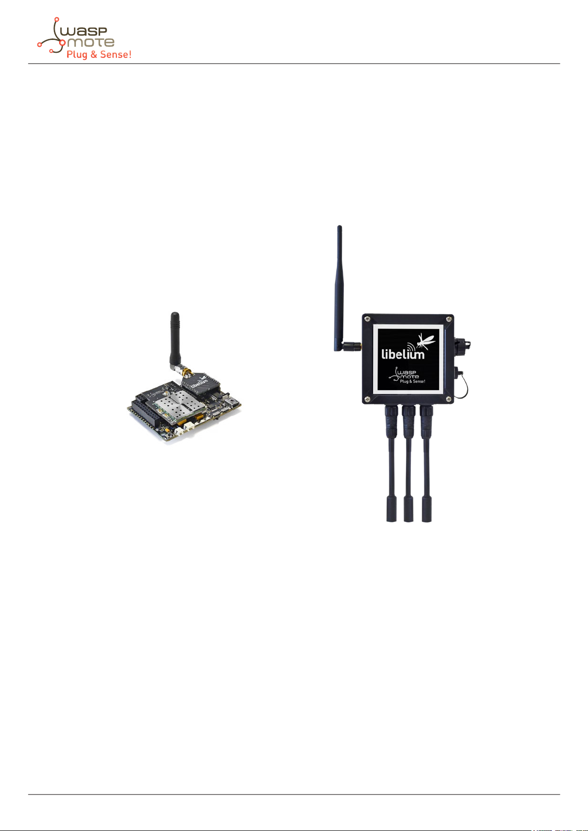
4. Waspmote vs Waspmote Plug & Sense!
Waspmote is the original line in which developers have a total control over the hardware device. You can physically
access to the board and connect new sensors or even embed it in your own products as an electronic sensor
device.
The Waspmote Plug & Sense! line allows developers to forget about electronics and focus on services and
applications. You can deploy wireless sensor networks in an easy and scalable way ensuring minimum maintenance
costs. The platform consists of a robust waterproof enclosure with specic external sockets to connect the
sensors, the solar panel, the antenna and even the USB cable in order to reprogram the node. It has been specially
designed to be scalable, easy to deploy and maintain.
Figure: Waspmote
Figure: Waspmote Plug & Sense!
-9- v8.6

General view
5. General view
This section shows main parts of Waspmote Plug & Sense! and a brief description of each one. In later sections
all parts will be described deeply.
5.1. Specications
• Material: polycarbonate
• Sealing: polyurethane
• Cover screws: stainless steel
• Ingress protection: IP65
• Impact resistance: IK08
• Rated insulation voltage AC: 690 V
• Rated insulation voltage DC: 1000 V
• Heavy metals-free: Yes
• Weatherproof: true - nach UL 746 C
• Ambient temperature (min.): -30 °C*
• Ambient temperature (max.): 70 °C*
• Approximated weight: 800 g
*
Temporary extreme temperatures are supported. Regular recommended usage: -20, +60 ºC.
In the pictures included below it is shown a general view of Waspmote Plug & Sense! main parts. Some elements
are dedicated to node control, others are designated to sensor connection and other parts are just identication
elements. All of them will be described along this guide.
164 mm
85 mm
124 mm
175 mm
410 mm
122 mm
160 mm
Figure: Main view of Waspmote Plug & Sense!
-10- v8.6
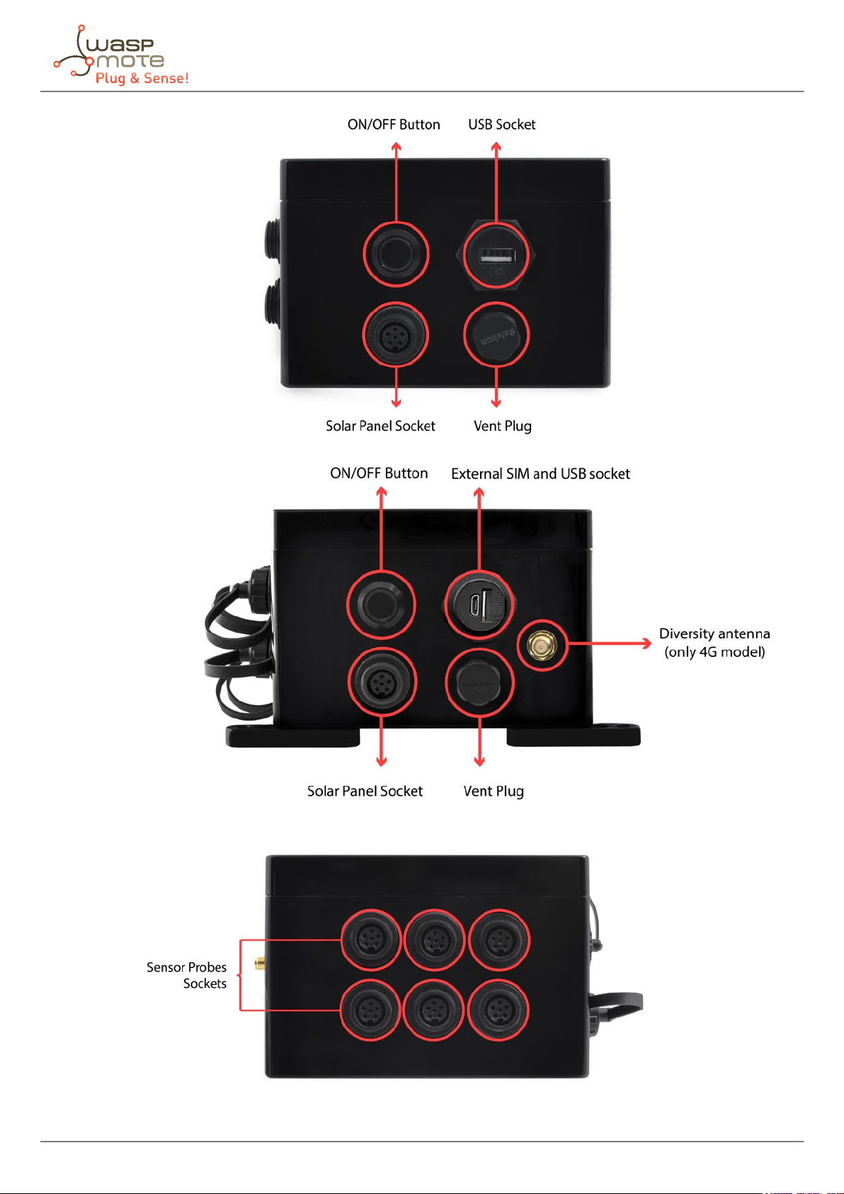
Figure: Control side of the enclosure
General view
Figure: Control side of the enclosure for 4G model
Figure: Sensor side of the enclosure
-11- v8.6
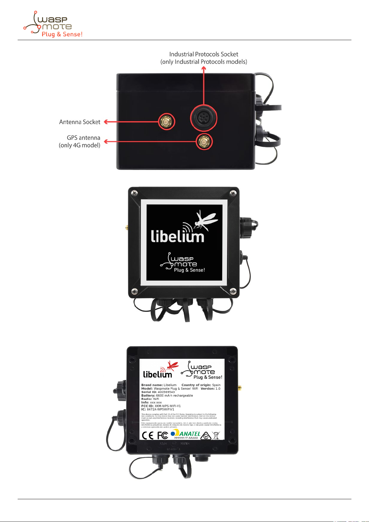
Figure: Antenna side of the enclosure
General view
Figure: Front view of the enclosure
Figure: Back view of the enclosure
-12- v8.6
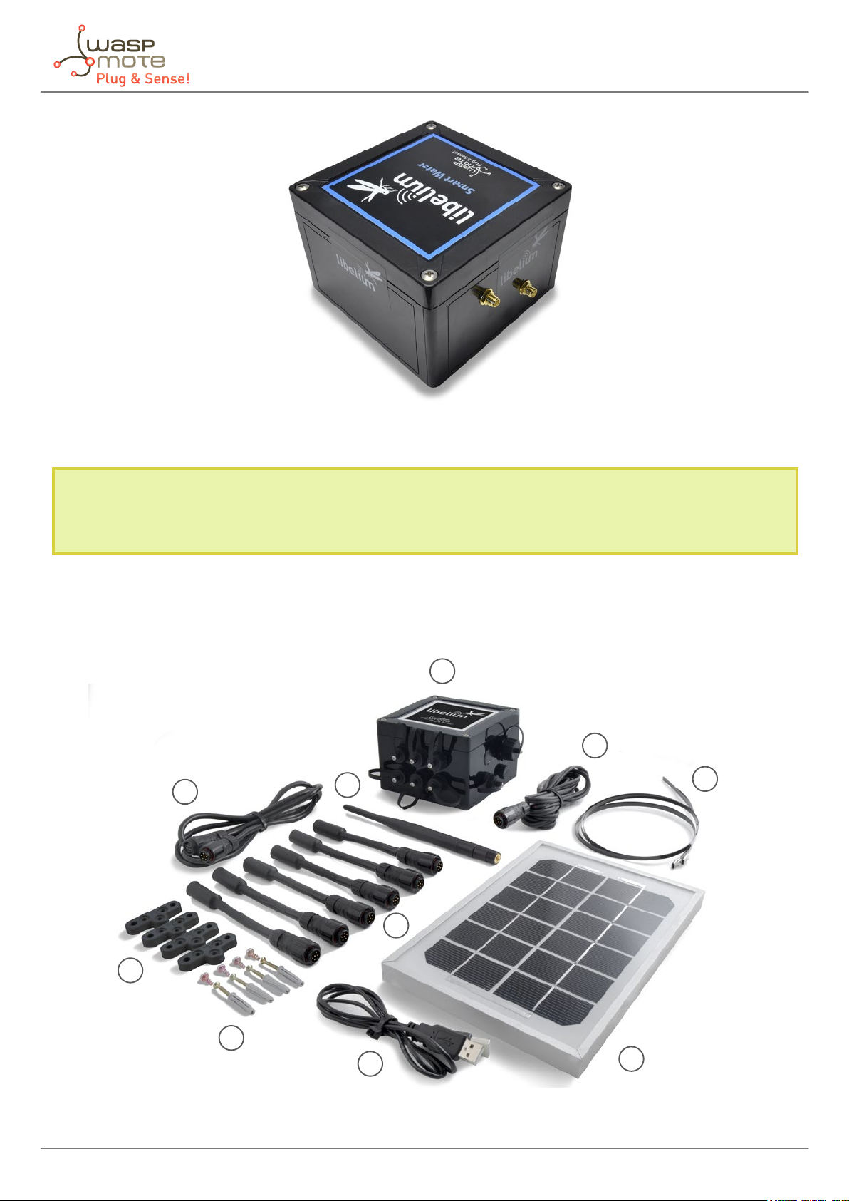
Figure: Warranty stickers of the enclosure
General view
Important note: Do not handle black stickers seals of the enclosure (Warranty stickers). Their integrity is the proof
that Waspmote Plug & Sense! has not been opened. If they have been handled, damaged or broken, the warranty is
automatically void.
5.2. Parts included
Next picture shows Waspmote Plug & Sense! and all of its elements. Some of them are optional accessories that
may not be included.
1
9
8
5
6
2
7
10
4
Figure: Waspmote Plug & Sense! accessories: 1 enclosure, 2 sensor probes, 3 external solar panel, 4 USB cable, 5 antenna, 6 cable ties,
7 mounting feet (screwed to the enclosure), 8 extension cord, 9 solar panel cable, 10 wall plugs & screws
-13- v8.6
3
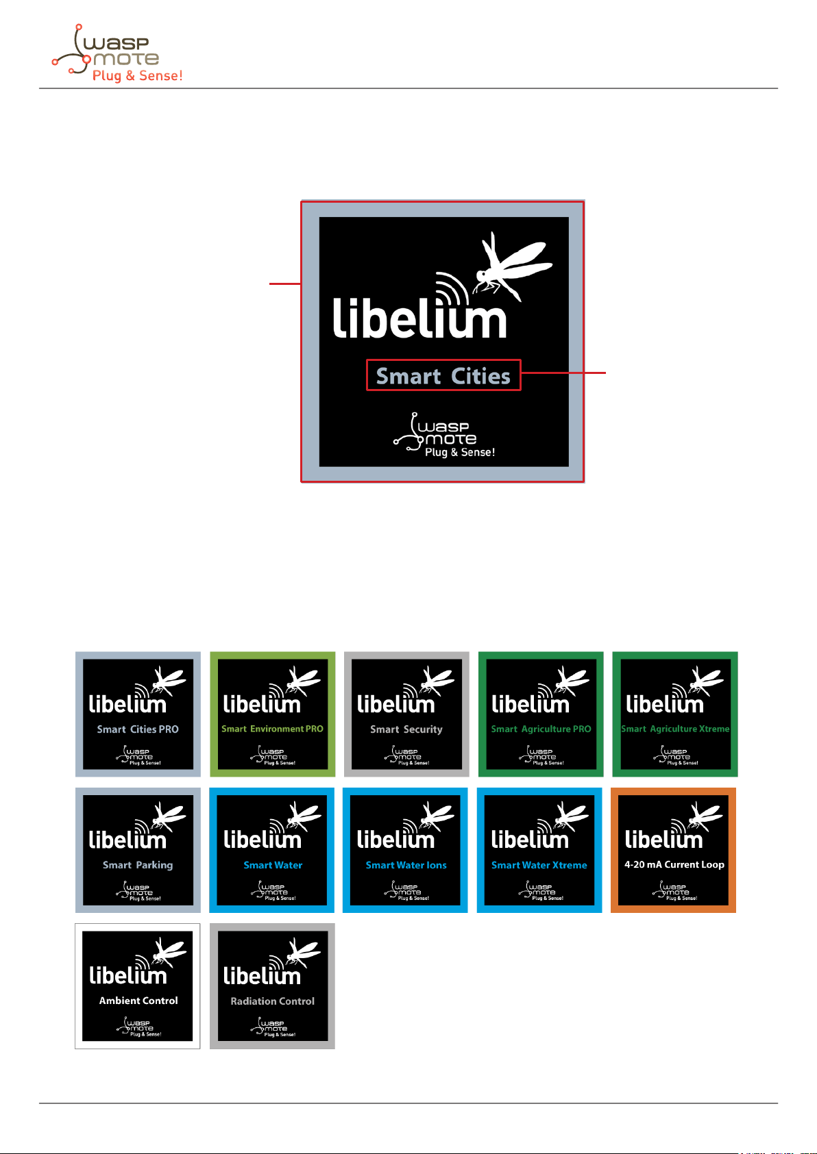
5.3. Identication
Each Waspmote model is identied by stickers. Next gure shows front sticker.
Model identication colour
General view
Enclosure model
Figure: Front sticker of the enclosure
There are many congurations of Waspmote Plug & Sense! line, all of them identied by one unique sticker. Next
image shows all possibilities.
Figure: Dierent front stickers
-14- v8.6
General view
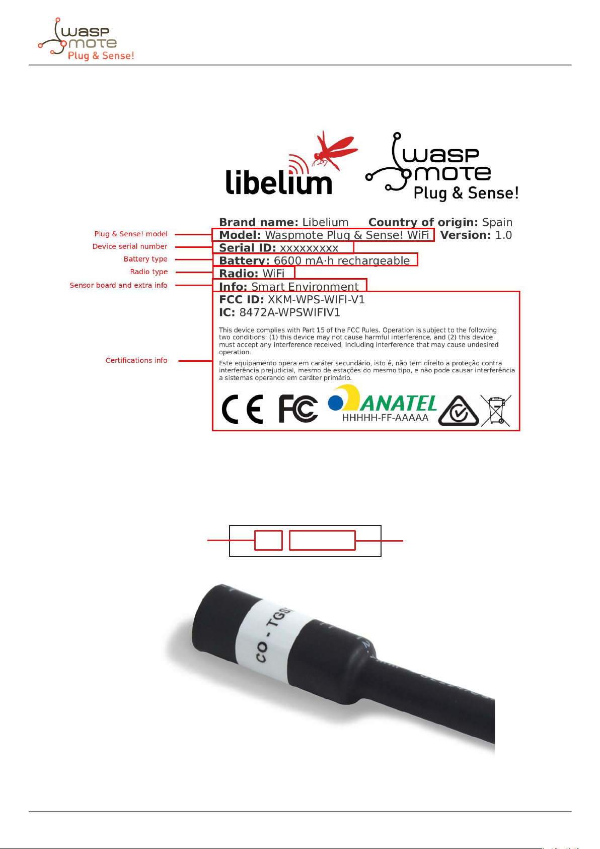
Moreover, Waspmote Plug & Sense! includes a back sticker where it is shown identication numbers, radio MAC
addresses, etc. It is highly recommended to annotate this information and save it for future maintenance. Next
gure shows it in detail.
Figure: Back sticker
Sensor probes are identied too by a sticker showing the measured parameter and the sensor manufacturer
reference.
Measure
parameter
CO - TGS2442
Figure: Sensor
Figure: reference
Figure: Sensor probe identication sticker
-15- v8.6
Sensor probes
6. Sensor probes
All sensing capabilities of Waspmote Plug & Sense! are provided by sensor probes. Each sensor probe contains one
sensor, some necessary protections against outdoor environmental conditions and a waterproof male connector.
The standard length of a sensor probe is about 150 mm, including waterproof connector, but it could vary due to
some sensors need special dimensions. Weight of a standard probe rounds 20 g, but there are some special cases
which this weight can rise.
Sensor probes are designed to be used in vertical position (with sensor looking to the ground). In this position, the
protection cap of each sensor probe is eective against bad weather conditions.
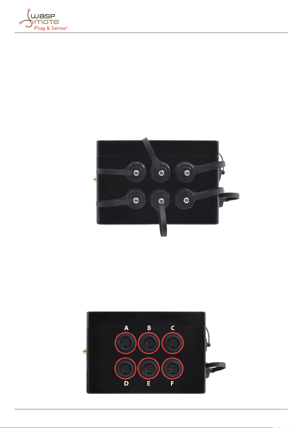
Each model has six dedicated sockets to connect sensor probes. They are located in the sensor side, as shown
below. Each socket has a protecting cap. When one of the six sensor connectors is not used, be sure the cap is
screwed to protect the connector.
Figure: Enclosure sensor side with protection caps
Each sensor socket is identied by a letter from A to F (see picture below). The user should understand that each
sensor probe should go in a dedicated socket, due to each sensor has dierent power requirements (current and
voltage levels), dedicated circuitry, etc. So please see corresponding section about where to connect each probe.
Always be sure you connected probes in the right socket, otherwise they can be damaged.
Never connect a sensor not provided by Libelium to any of the sensor connectors. The electronics system inside
can be damaged and the warranty will be automatically void.
Figure: Enclosure sensor side without protection caps
-16- v8.6
Sensor probes
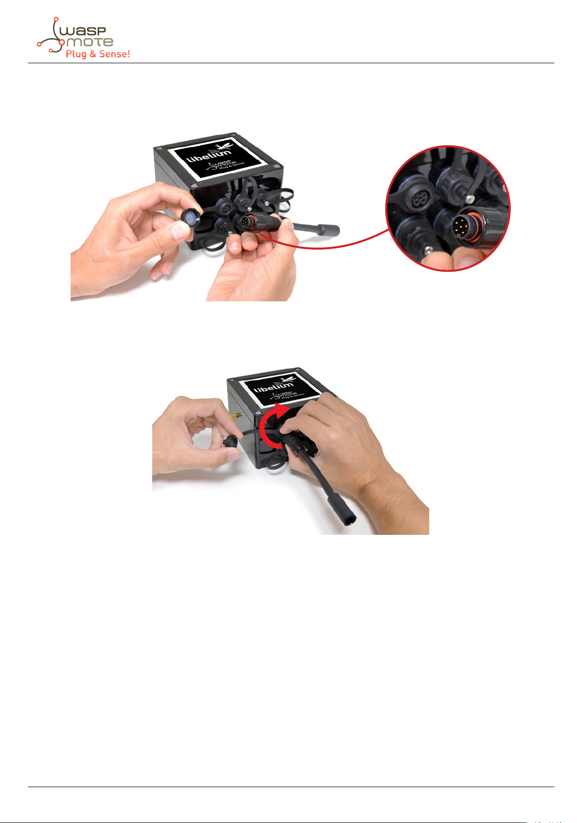
It should be taken into account that any sensor probe connector has only one matching position with a sensor
probe. The user should align the sensor probe connector looking at the little notch of the connector (see image
below). Notice that the sensor connector is male type and the enclosure sensor connector is female type.
Figure: Detail of sensor waterproof connector
Besides that, there is a locking nut which should be screwed till the connector is completely xed to the enclosure.
Figure: Connecting a sensor probe to the enclosure
Please use only sensors ocially provided by Libelium. Any other sensor can damage Waspmote Plug & Sense!
and void the warranty.
-17- v8.6
Sensor probes
6.1. Sensor probes types
Libelium provides many dierent sensor probes depending on what is going to be measured. This section
describes main features of each type. If further information is required, please refer for the corresponding sensor
board guide available on Libelium website.
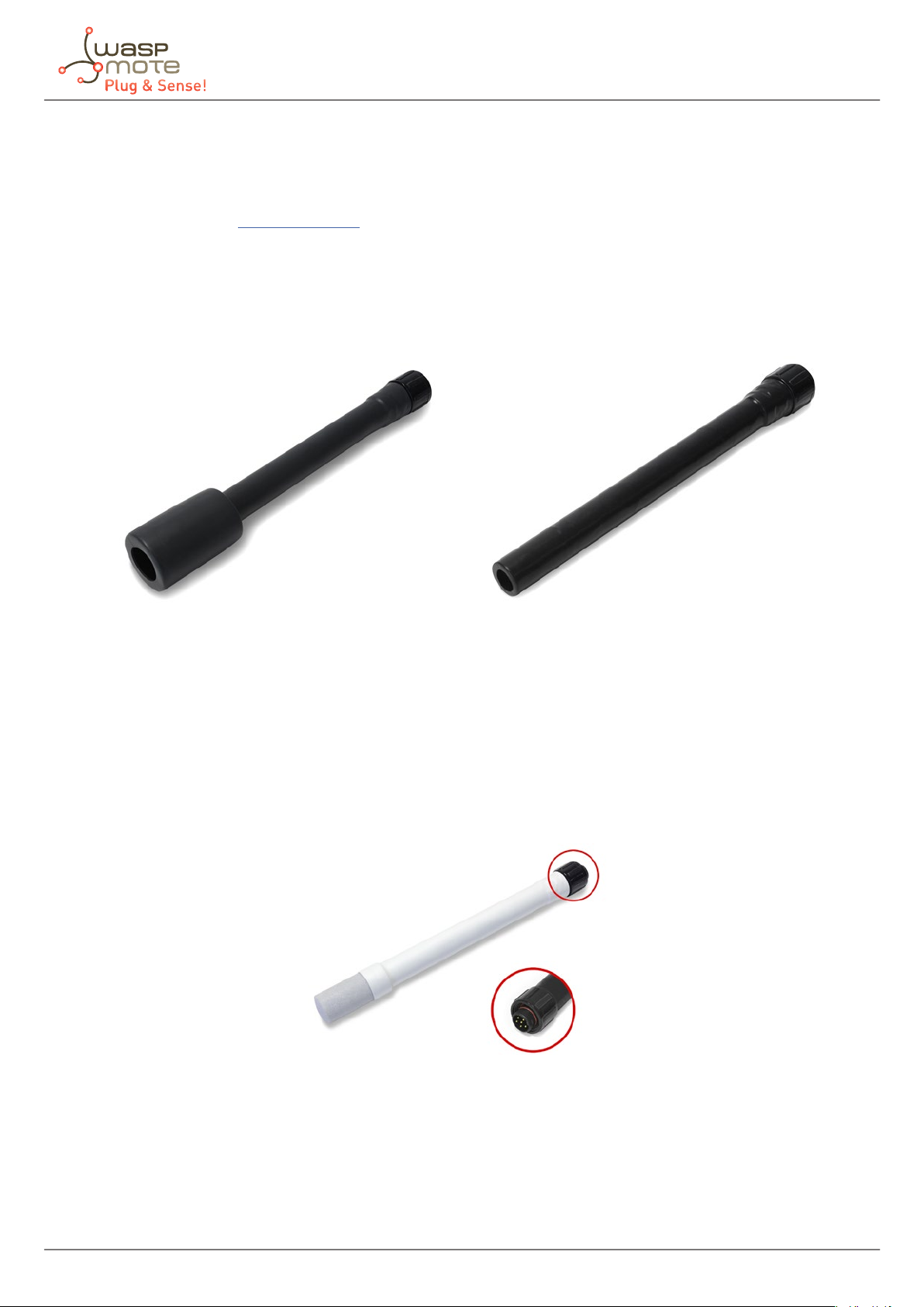
Standard type
This sensor probe is the most common. The sensor is placed inside a plastic cylinder acting as a protection against
rain and water, but allowing sensor interact with environment to measure necessary parameters. Besides, the
sensor is kept always straight and the size and shape of the probes are standardized as maximum as possible.
Figure: Standard sensor probe
Sensor probes of this type are all the gas sensors of the Smart Environment and the Smart Environment PRO
models (except for the temperature, humidity and pressure sensor and the particle matter sensor).
White protection probe
This probe is designed to reduce sunlight eects and prevent from water and rain, but allowing humidity
measurement.
Only the temperature, humidity and pressure sensor include this special protection.
Figure: Temperature, humidity and pressure probe
-18- v8.6
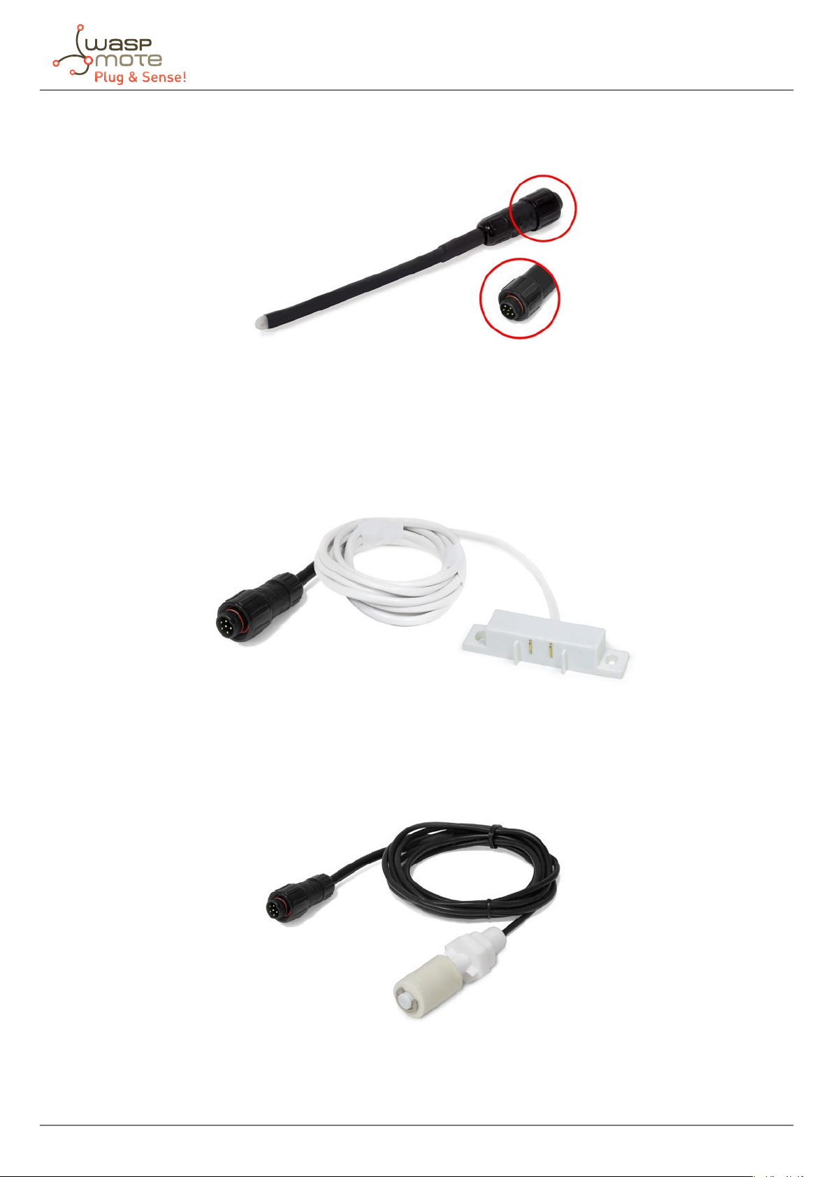
Luminosity - LDR probe
This probe is designed to allow sunlight go thought a transparent protection.
Figure: Luminosity probe
Liquid Presence probe (point)
This probe is designed to allow placing the sensor near its application.
Sensor probes
Figure: Liquid Presence probe (point)
Liquid level probe
This probe is designed to measure liquid levels.
Figure: Liquid level probe
-19- v8.6

Liquid ow probe
This probe is designed to measure liquid ow through a pipe.
Figure: Liquid ow probe
Hall eect probe
This probe is designed to control the opening of doors, windows, etc.
Sensor probes
Figure: Hall eect probe
Solar radiation probe
This probe is designed to measure solar radiation.
Figure: Solar radiation probe
-20- v8.6
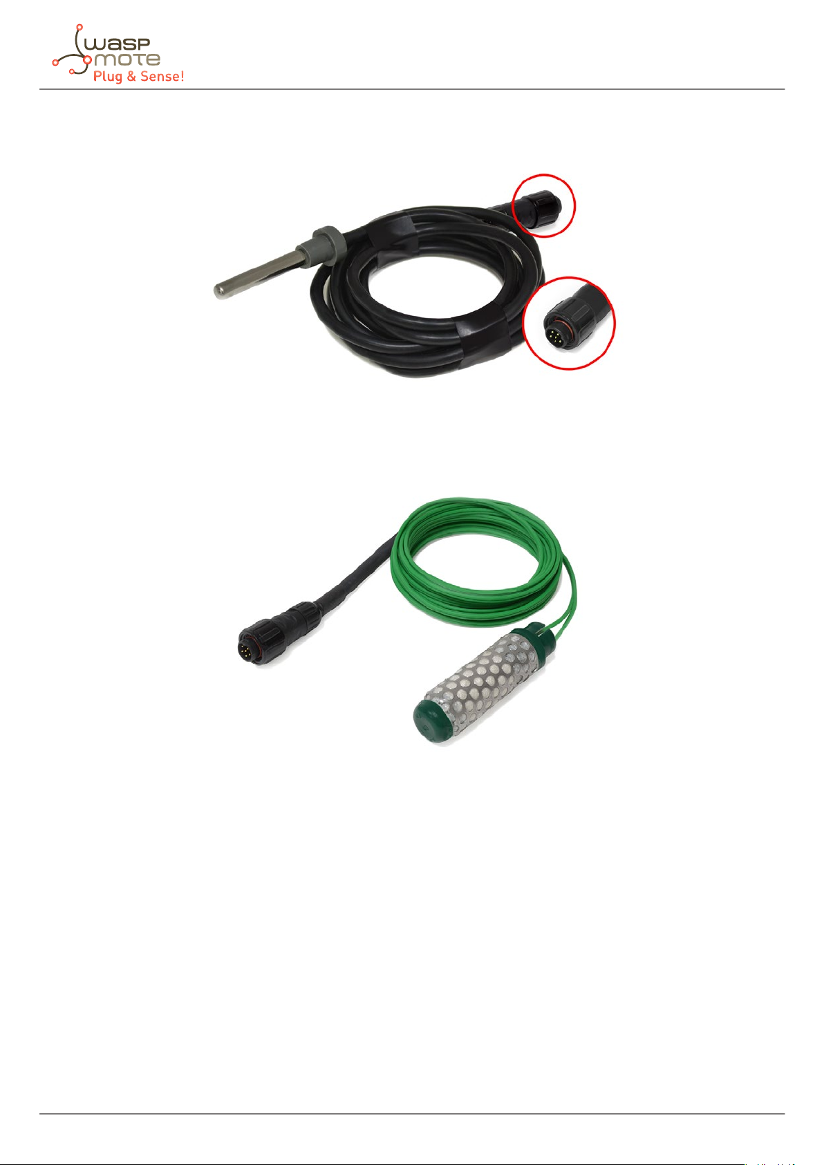
Soil temperature probe
This probe is designed to be buried into the ground to measure its temperature.
Figure: Soil temperature probe
Soil moisture probe
This probe is designed to be buried into the ground to measure its moisture.
Sensor probes
Figure: Soil moisture probe
-21- v8.6
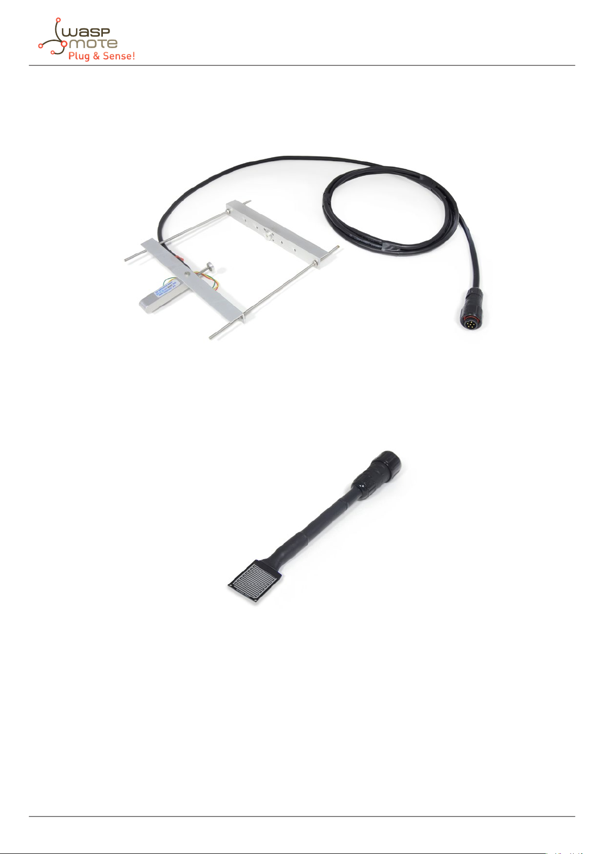
Dendrometer probe
This probe is designed to measure trunk, stem and fruit diameter of vegetables.
Sensor probes
Figure: Dendrometer probe
Leaf wetness probe
This probe is designed to measure wetness on vegetable leafs.
Figure: Leaf wetness probe
-22- v8.6
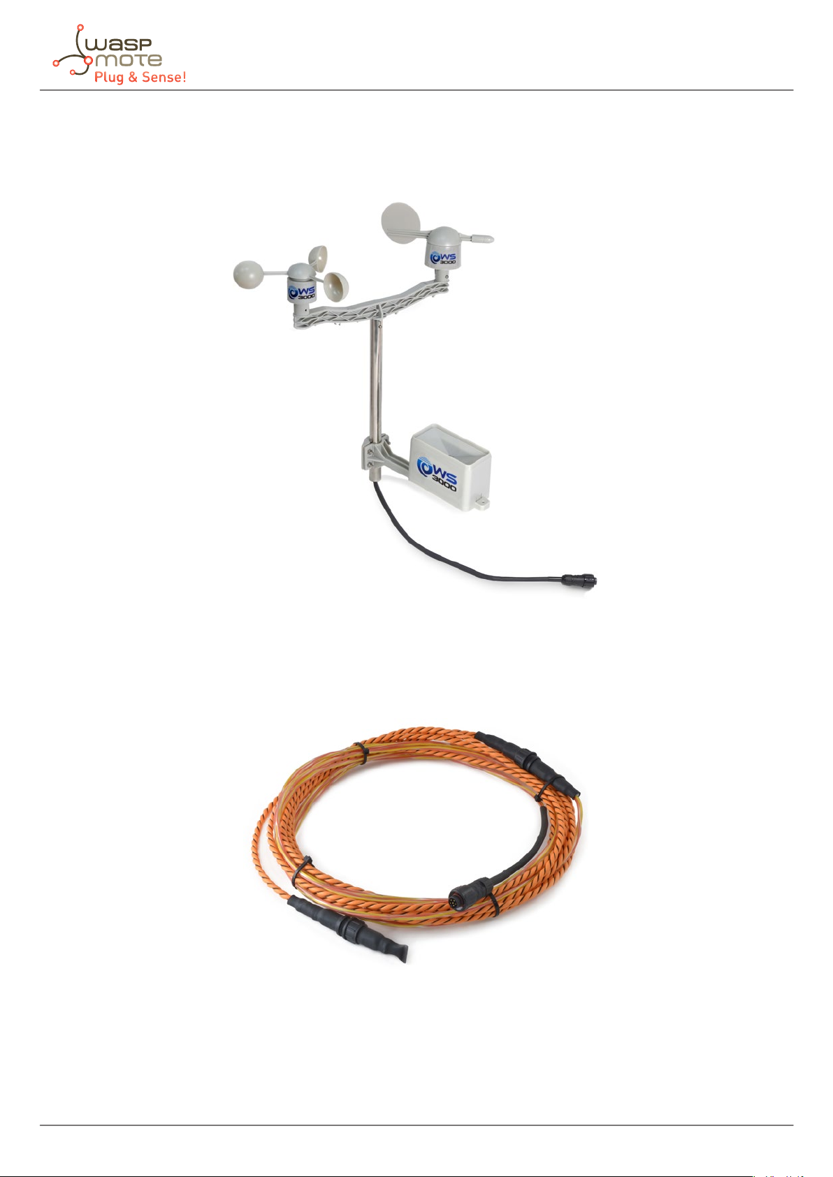
Weather Station WS-3000 probe
This probe is designed to measure wind direction, wind speed and rain.
Sensor probes
Figure: Weather Station WS-3000 probe
Liquid Presence probe (line)
This probe is designed to allow placing the sensor near its application.
Figure: Liquid Presence probe (line)
-23- v8.6
Sensor probes
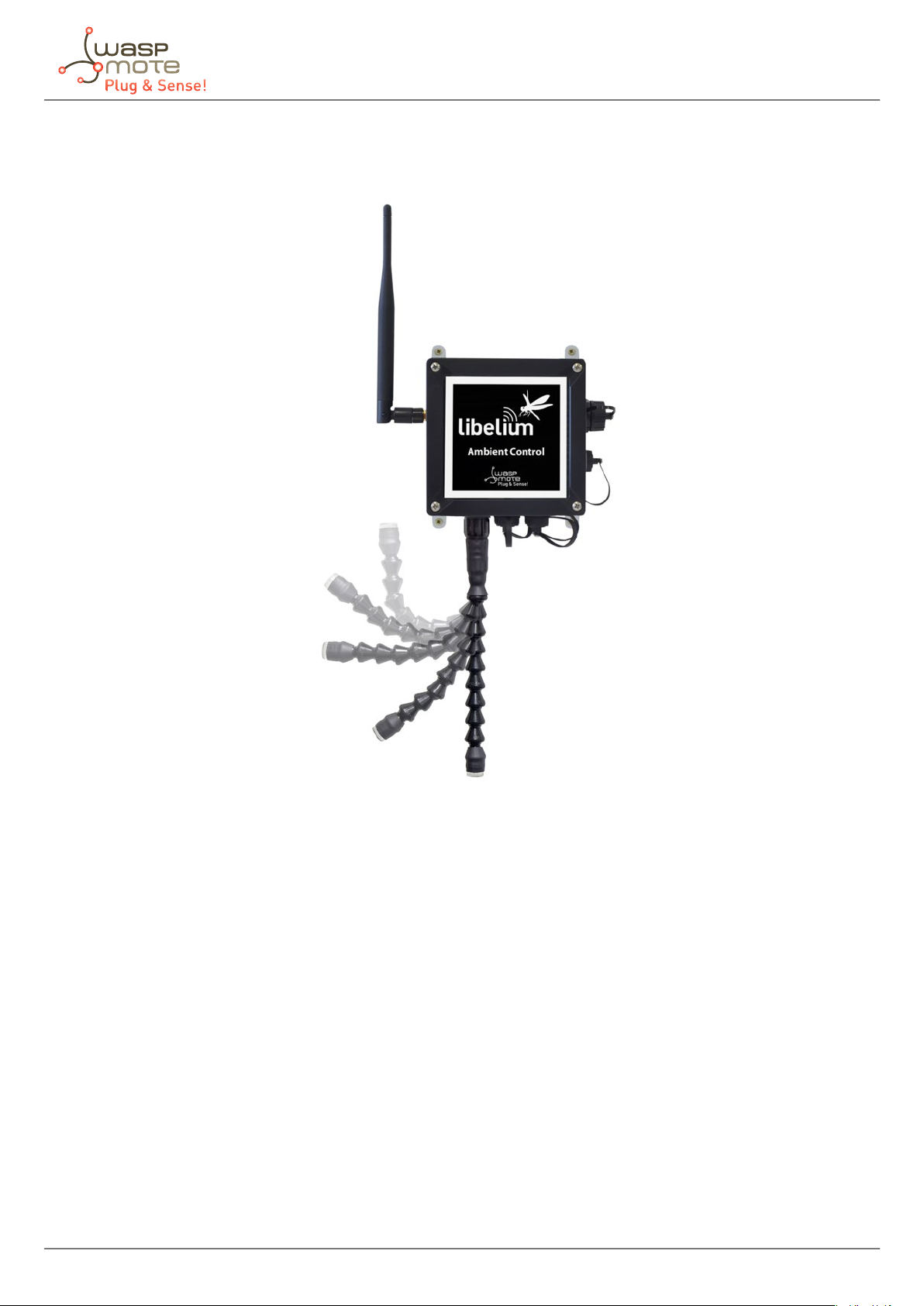
Directionable type
This type of probe is only for some sensors. The sensor is placed inside a plastic modular hose that allows us to
point them where we want to measure with it.
Figure: Congurations of directionable sensor probes
-24- v8.6
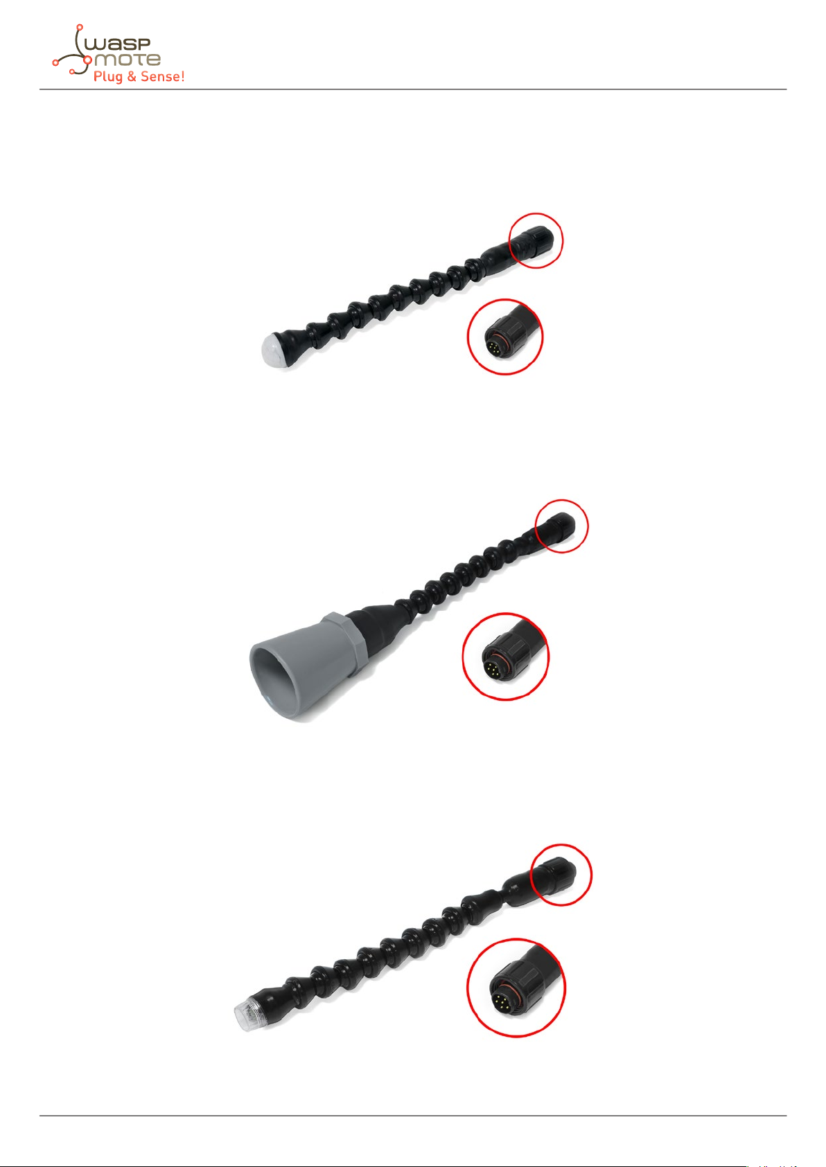
Sensor probes of this type are:
• Presence - PIR directionable probe
This probe is designed to allow infrared light trough a lens, necessary for presence applications.
Figure: Presence (PIR) directionable probe
• Ultrasound sensor directionable probe
This probe is designed to measure distances using ultrasonic waves.
Sensor probes
Figure: Ultrasound directionable probe
• Luminosity (Luxes accuracy) directionable probe
This probe is designed to measure luxes indoors and outdoors.
Figure: Luminosity (luxes accuracy) directionable probe
-25- v8.6
Sensor probes
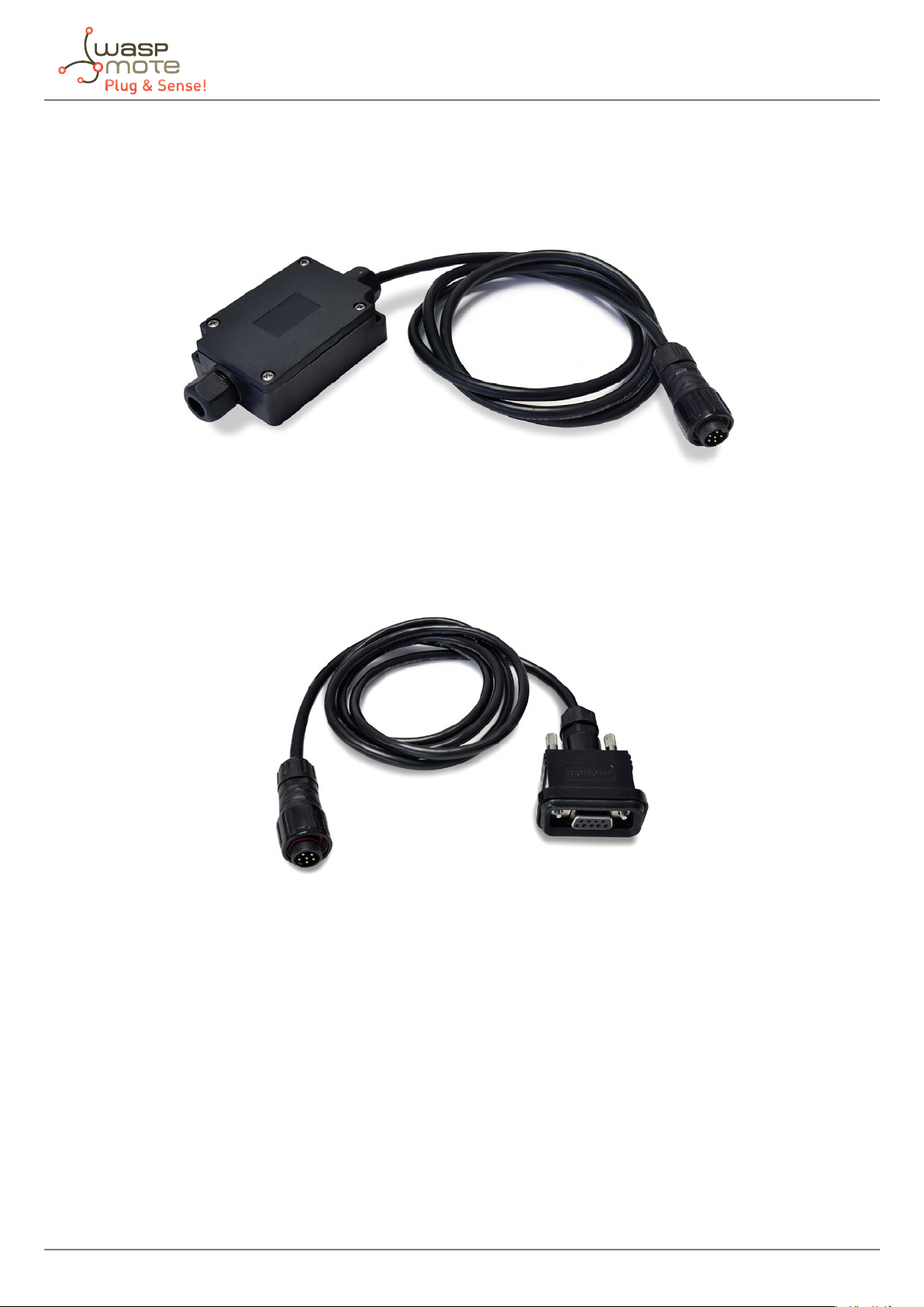
• Terminal box probe
This probe allow access to the 4-20 mA current loop board signals, to the relay contacts on Smart Security models
(max 30 VDC, 1 A) and also to allow access to the optional Industrial Protocols feature (RS-485, Modbus and CAN
Bus) in the Waspmote Plug & Sense! encapsulated line. A waterproof terminal block junction box is provided as a
probe, making the connections on industrial environments or outdoor applications easier.
Figure: Terminal box probe
• DB9 probe
The DB9 connector is commonly used in many applications with data transmission on industrial ambients.
Libelium provides this probe with a standard DB9 female connector and a length of 1.5 meters.
Figure: DB9 probe
-26- v8.6
Sensor probes
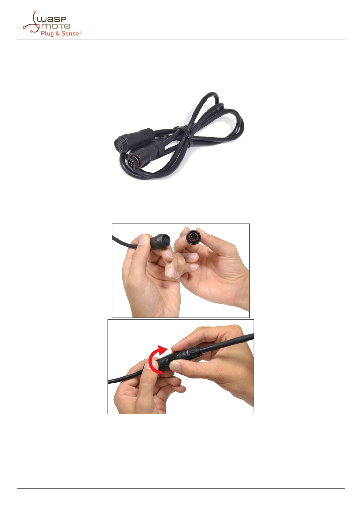
6.2. Extension cord
This element is used when one sensor needs to be placed far from the node. Two lengths are available: 1.5 and
3 m. Next picture shows an extension cord.
Figure: Extension cord accessory
The extension cord has a female and a male connector. The rst one (female) should be connected to the sensor
probe. Next picture shows that.
Figure: Connecting a probe with an extension cord
-27- v8.6
Moreover, the male connector should be connected to the enclosure as shown below.
Sensor probes
Figure: Connecting an extension cord to the enclosure
-28- v8.6
Internal sensors
7. Internal sensors
7.1. Accelerometer
Waspmote has a built-in acceleration sensor which informs the mote of acceleration variations experienced on
each one of the 3 axes (X, Y, Z). The integration of this sensor allows the measurement of acceleration on the 3
axes (X, Y, Z), establishing 2 kinds of events: Free Fall and Direction Detection Change.
Z
Y
X
Figure: Axis direction in Waspmote Plug & Sense!
Complete information can be found in the Accelerometer Programming Guide.
-29- v8.6

8. Radio modules
Waspmote Plug & Sense! may integrate many radio modules for wireless communications.
Radio modules
Radio Protocol
XBee-PRO 802.15.4
EU
XBee-PRO 802.15.4 802.15.4 2.4 GHz 18 dBm -100 dBm 1600 m
XBee ZigBee 3 ZigBee 3 2.4 GHz 8 dBm -103 dBm 1200 m CE
XBee 868LP RF 868 MHz 14 dBm -106 dBm 8.4 km CE
XBee 900HP US RF 900 MHz 24 dBm -110 dBm 15.5 km FCC, IC
XBee 900HP BR RF 900 MHz 24 dBm -110 dBm 15.5 km ANATEL
XBee 900HP AU RF 900 MHz 24 dBm -110 dBm 15.5 km RCM
WiFi
4G EU/BR
4G US v2
4G AU
Sigfox EU Sigfox 868 MHz 16 dBm -126 dBm
Sigfox US Sigfox 900 MHz 24 dBm -127 dBm
802.15.4 2.4 GHz 10 dBm -100 dBm 750 m CE
WiFi
(HTTP(S),
FTP, TCP,
UDP)
4G/3G/2G
(HTTP, FTP,
TCP, UDP)
GPS
4G/3G
(HTTP, FTP,
TCP, UDP)
4G
(HTTP, FTP,
TCP, UDP)
Frequency
bands
2.4 GHz 17 dBm -94 dBm 500 m
800, 850, 900,
1800, 2100, 2600
MHz
700, 850, 1700,
1900 MHz
700, 1800, 2600
MHz
Transmission
power
4G: class 3
(0.2 W, 23 dBm)
4G: class 3
(0.2 W, 23 dBm)
4G: class 3
(0.2 W, 23 dBm)
Sensitivity Range*
4G: -102
dBm
4G: -103
dBm
4G: -102
dBm
- km - Typical
base station
range
- km - Typical
base station
range
- km - Typical
base station
range
- km - Typical
base station
range
- km - Typical
base station
range
Certication
FCC, IC,
ANATEL, RCM
CE, FCC, IC,
ANATEL, RCM
CE, ANATEL
FCC, IC, PTCRB,
AT&T
RCM
FCC, IC
CE
LoRaWAN EU LoRaWAN 868 MHz 14 dBm -136 dBm > 15 km CE
LoRaWAN US LoRaWAN 900 MHz 18.5 dBm -136 dBm > 15 km FCC, IC
LoRaWAN AU LoRaWAN 915-928 MHz 18.5 dBm -136 dBm > 15 km -
LoRaWAN IN LoRaWAN 865-867 MHz 18.5 dBm -136 dBm > 15 km
* Line of sight, Fresnel zone clearance and 5dBi dipole antenna.
-
These modules have been chosen for their high receiving sensitivity and transmission power, as well as for being
802.15.4 compliant (XBee-802.15.4 model) and ZigBee-Pro v2007 compliant (XBee-ZB model).
-30- v8.6

8.1. XBee-PRO 802.15.4
Radio modules
Radio version Frequency
XBee-PRO 802.15.4 EU
XBee-PRO 802.15.4 18 dBm 1600 m
* To determine your range, perform a range test under your operating conditions
The frequency used is the free band of 2.4 GHz, using 12 channels with a bandwidth of 5 MHz per channel.
Figure: Frequency channels in the 2.4 GHz band
2.4 GHz
Channel Number Frequency
0x0C – Channel 12 2.405 – 2.410 GHz
0x0D – Channel 13 2.410 – 2.415 GHz
Transmission
power
10 dBm
Sensitivity Range*
-100 dBm
750 m
0x0E – Channel 14 2.415 – 2.420 GHz
0x0F – Channel 15 2.420 – 2.425 GHz
0x10 – Channel 16 2.425 – 2.430 GHz
0x11 – Channel 17 2.430 – 2.435 GHz
0x12 – Channel 18 2.435 – 2.440 GHz
0x13 – Channel 19 2.440 – 2.445 GHz
0x14 – Channel 20 2.445 – 2.450 GHz
0x15 – Channel 21 2.450 – 2.455 GHz
0x16 – Channel 22 2.455 – 2.460 GHz
0x17 – Channel 23 2.460 – 2.465 GHz
Figure: Channels used by the XBee modules in 2.4GHz
The XBee-PRO 802.15.4 modules comply with the standard IEEE 802.15.4 which denes the physical level and the
link level (MAC layer). The XBee modules add certain functionalities to those contributed by the standard, such as:
• Node discovery: certain information has been added to the packet headers so that they can discover other
nodes on the same network. It allows a node discovery message to be sent, so that the rest of the network
nodes respond indicating their data (Node Identier, @MAC, @16 bits, RSSI).
• Duplicated packet detection: This functionality is not set out in the standard and is added by the XBee
modules.
-31- v8.6

Radio modules
The classic topology of this type of network is a star topology, as the nodes establish point to point connections
with brother nodes through the use of parameters such as the MAC or network address.
Figure: Star topology
Regarding the transmission power, it can be adjusted to several values depending on the radio version:
Parameter XBee-PRO 802.15.4 XBee-PRO 802.15.4
EU
0 10 dBm -3 dBm
1 12 dBm -3 dBm
2 14 dBm 2 dBm
3 16 dBm 8 dBm
4 18 dBm 10 dBm
Figure: Transmission power values
Related API libraries: WaspXBeeCore.h, WaspXBeeCore.cpp, WaspXBee802.h, WaspXBee802.cpp
All information about their programming and operation can be found in the 802.15.4 Networking Guide.
All the documentation is located in the Development section in the Libelium website.
-32- v8.6

8.2. XBee ZigBee 3
Radio version Frequency Transmission power Sensitivity Range*
XBee ZigBee 3 2.4 GHz 8 dBm -103 dBm 1200 m
* To determine your range, perform a range test under your operating conditions
Figure: XBee ZigBee 3
Radio modules
As the ZigBee standard is supported in the IEEE 802.15.5 link layer, it uses the same channels as described in the
previous section, with the peculiarity that the XBee ZigBee 3 model limits the number of channels to 16.
The XBee ZigBee 3 modules comply with the ZigBee 3.0 standard. These modules add certain functionalities to
those contributed by ZigBee, such as:
• Node discovery: some headings are added so that other nodes within the same network can be discovered.
It allows a node discovery message to be sent, so that the rest of the network nodes respond indicating their
specic information (Node Identier, @MAC, @16 bits, RSSI).
• Duplicated packet detection: This functionality is not set out in the standard and is added by the XBee modules.
The topologies in which these modules can be used are: star and tree.
Figure: Star topology
-33- v8.6

Radio modules
Figure: Tree topology
Related API libraries: WaspXBeeCore.h, WaspXBeeCore.cpp, WaspXBeeZB.h, WaspXBeeZB.cpp.
All information about their programming and operation can be found in the ZigBee Networking Guide.
All the documentation is located in the Development section in the Libelium website.
-34- v8.6

8.3. XBee 868LP
Radio modules
Radio
version
XBee 868LP 863 - 870 MHz 14 dBm -106 dBm 8.4 km
* To determine your range, perform a range test under your operating conditions
Note: The XBee 868 MHz module is provided with 4.5dBi antenna, which enables maximum range.
The frequency used is the 868 MHz band, using 30 software selectable channels. Channels are spaced 100 kHz
apart. The transmission rate is 10 kbps.
The classic topology for this type of network is a star topology, as the nodes can establish point-to-point
connections with brother nodes through the use of the MAC address.
Frequency Transmission power Sensitivity Range*
Figure: Star topology
Regarding the transmission power, it can be adjusted to several values:
Parameter XBee 868LP
0 3 dBm
1 7 dBm
2 10 dBm
3 12 dBm
4 14 dBm
Figure: Transmission power values
Related API libraries: WaspXBeeCore.h, WaspXBeeCore.cpp, WaspXBee868LP.h, WaspXBee868LP.cpp
All information about their programming and operation can be found in the 868 Networking Guide.
All the documentation is located in the Development section in the Libelium website.
-35- v8.6

Radio modules
8.4. XBee-PRO 900HP
Radio version Frequency Transmission power Sensitivity Range*
XBee-PRO 900HP US 902 - 928 MHz
902 - 906.8 MHz
915.6 - 928 MHz
XBee-PRO 900HP AU 915.6 - 928 MHz
* To determine your range, perform a range test under your operating conditions
The frequency used is the 900 MHz band, using 64 software selectable channels. Channels are spaced 400 kHz
apart. The transmission rate is 10 kbps. There are dierent versions of the XBee 900HP: USA & Canada, Brazil and
Australia.
The dierent versions dier mainly in the available channels, which are hard-coded in the XBee. Be aware that it is
not possible to change from one version to other with just a rmware change. According to the country where
the user is located, a dierent version must be chosen.
The classic topology for this type of network is a star topology, as the nodes can establish point-to-point connections
with brother nodes through the use of parameters such as the MAC address or that of the network.
24 dBm -110 dBm 15.5 kmXBee-PRO 900HP BR
Figure: Star topology
API libraries: WaspXBeeCore.h, WaspXBeeCore.cpp, WaspXBee900HP.h, WaspXBee900HP.cpp
All information about their programming and operation can be found in the 900 Networking Guide.
All the documentation is located in the Development section in the Libelium website.
-36- v8.6

Radio modules
8.5. LoRaWAN modules
LoRaWAN is a Low Power Wide Area Network (LPWAN) specication intended for wireless battery-operated
devices in regional, national or global network. LoRaWAN target key requirements of Internet of things such
as secure bi-directional communication, mobility and localization services. This standard will provide seamless
interoperability among smart Things without the need of complex local installations and gives back the freedom
to the user, developer, businesses enabling the role out of Internet of Things.
LoRaWAN network architecture is typically laid out in a star-of-stars topology in which gateways is a transparent
bridge relaying messages between end-devices and a central network server in the back-end. Gateways
are connected to the network server via standard IP connections while end-devices use single-hop wireless
communication to one or many gateways.
Figure: LoRaWAN network
Communication between end-devices and gateways is spread out on dierent frequency channels and data rates.
The selection of the data rate is a trade-o between communication range and message duration. Due to the
spread spectrum technology, communications with dierent data rates do not interfere with each other and
create a set of “virtual” channels increasing the capacity of the gateway. To maximize both battery life of the enddevices and overall network capacity, the LoRaWAN network server is managing the data rate and RF output for
each end-device individually by means of an adaptive data rate (ADR) scheme.
National wide networks targeting Internet of Things such as critical infrastructure, condential personal data or
critical functions for the society has a special need for secure communication. This has been solved by several
layer of encryption.
Protocol: LoRaWAN 1.0, Class A
LoRaWAN-ready
Frequency:
• LoRaWAN EU module: 868 MHz and 433 MHz ISM bands
• LoRaWAN US module: 902-928 MHz ISM band
• LoRaWAN AU module: 915-928 MHz ISM band
• LoRaWAN IN module: 865-867 MHz ISM band
• LoRaWAN ASIA-PAC / LATAM module: 923 MHz ISM band
TX power:
• LoRaWAN EU module: up to 14 dBm
• LoRaWAN US module: up to 18.5 dBm
• LoRaWAN AU module: up to 18.5 dBm
• LoRaWAN IN module: up to 18.5 dBm
-37- v8.6

Radio modules
• LoRaWAN ASIA-PAC / LATAM module: up to 18.5 dBm
Sensitivity: down to -136 dBm
Range: >15 km at suburban and >5 km at urban area. Typically, each base station covers some km. Check the
LoRaWAN Network in your area.
Chipset consumption:
• LoRaWAN EU module: 38.9 mA
• LoRaWAN US module: 124.4 mA
• LoRaWAN AU module: 124.4 mA
• LoRaWAN IN module: 124.4 mA
• LoRaWAN ASIA-PAC / LATAM module: 124.4 mA
Radio data rate:
• LoRaWAN EU module: from 250 to 5470 bps
• LoRaWAN US module: from 250 to 12500 bps
• LoRaWAN AU module: from 250 to 12500 bps
• LoRaWAN IN module: from 250 to 12500 bps
• LoRaWAN ASIA-PAC / LATAM module: from 250 to 12500 bps
Receiver: purchase your own base station or use networks from LoRaWAN operators
Related API libraries: WaspLoRaWAN.h, WaspLoRaWAN.cpp
All the information about their programming and operation can be found in the LoRaWAN Networking Guide
available at Development section of Libelium website.
-38- v8.6

Radio modules
8.6. Sigfox modules
Sigfox is a private company that aims to build a worldwide network especially designed for IoT devices. The
network is cellular, with thousands of base stations deployed in each country. Sigfox technology oers very long
ranges for low-power, battery-constrained nodes. Sigfox is great for very simple and autonomous devices which
need to send small amounts of data to this ubiquitous network, taking advantage on the Sigfox infrastructure.
So Sigfox is similar to cellular (GSM-GPRS-3G-4G) but is more energy-ecient, and the annual fees are lower.
Sigfox uses a UNB (Ultra Narrow Band) based radio technology to connect devices to its global network. The use
of UNB is key to providing a scalable, high-capacity network, with very low energy consumption, while maintaining
a simple and easy to rollout star-based cell infrastructure.
• Frequency
- Sigfox EU module: ISM 868 MHz
- Sigfox US module: ISM 900 MHz
- Sigfox AU / APAC / LATAM module: ISM 900 MHz
• TX power
- Sigfox EU module: up to 16 dBm
- Sigfox US module: up to 24 dBm
- Sigfox AU / APAC / LATAM module: up to 24 dBm
• ETSI limitation: 140 messages of 12 bytes, per module per day
• Range: Typically, each base station covers some km. Check the Sigfox network.
• Chipset consumption
- Sigfox EU module: TX 51 mA @ 14 dBm
- Sigfox US module: TX 230 mA @ 24 dBm
- Sigfox AU / APAC / LATAM module: TX 230 mA @ 24 dBm
• Radio data rate: 100 bps
• Receive sensitivity: -126 dBm
• Sigfox certicate: Class 0u (the highest level)
The network operates in the globally available ISM bands (license-free frequency bands) and co-exists in these
frequencies with other radio technologies, but without any risk of collisions or capacity problems.
Sigfox is being rolled out worldwide. It is the responsibility of the system integrator to consult the catalog of SNOs
(Sigfox Network Operators) for checking coverage in the deployment area.
The Sigfox back-end provides a web application interface for device management and conguration of data
integration, as well as standards based web APIs to automate the device management and implement the data
integration.
Figure: Sigfox network
-39- v8.6

Radio modules
Related API libraries: WaspSigfox.h, Waspsigfox.cpp
All information about their programming and operation can be found in the Sigfox Networking Guide.
All the documentation is located in the Development section in the Libelium website.
-40- v8.6

Radio modules
8.7. WiFi PRO module
The WiFi PRO module oers and supports large variety of features, for example:
• Ten simultaneous TCP/UDP sockets
• DHCP client/server
• DNS client
• HTTP client
• HTTPS client
• FTP client
• NTP client
• Multiple SSIDs
• Roaming mode
• OTA feature. Refer to the Over the Air Programming Guide for more information.
The WiFi PRO module supports the SSL3/TLS1 protocol for secure sockets. On the WLAN interface it supports WEP,
WPA and WPA2 WiFi encryption.
The WiFi PRO module may connect to any standard router which is congured as Access Point (AP) and then send
data to other devices in the same network such as laptops and smart phones. Besides, they can send data directly
to a web server located on the Internet.
Instead of using a standard WiFi router as AP, the connection may be performed using a Meshlium device as
AP. Meshlium is the multiprotocol router designed by Libelium which is specially recommended for outdoor
applications as it is designed to resist the hardest conditions in real eld deployments. For more information
about Meshlium go to:
http://www.libelium.com/meshlium.
Related API libraries: WaspWiFi_PRO.h, WaspWiFi_PRO.cpp
All information about their programming and operation can be found in the WiFi Networking Guide.
All the documentation is located in the Development section in the Libelium website.
-41- v8.6

Radio modules
8.8. 4G module
The 4G module enables the connectivity to high speed LTE, HSPA+, WCDMA cellular networks in order to make
possible the creation of the next level of worldwide compatible projects inside the new “Internet of Things” era.
This communication module is specially oriented to work with Internet servers, implementing internally several
application layer protocols, which make easier to send the information to the cloud. We can make HTTP navigation,
downloading and uploading content to a web server. We can also set secure connections using SSL certicates
and setting TCP/IP private sockets. In the same way, the FTP protocol is also available which is really useful when
your application requires handling les.
The module includes a GPS/GLONASS receiver, able to perform geolocation services using NMEA sentences,
oering information such as latitude, longitude, altitude and speed; that makes it perfect to perform tracking
applications.
The 4G module oers the maximum performance of the 4G network as it uses 2 dierent antennas (normal +
diversity) for reception (MIMO DL 2x2), choosing the best received signal at any time and getting a maximum
download speed of 100 Mbps.
We chose the LE910 chipset family from Telit as it comprises the most complete 4G/LTE set of variants released
up to date. It counts with many dierent models, each one specically designed for one market but all of them
with the same footprint:
• LE910-EU (Europe/Brazil): CE, GCF, ANATEL
• LE910-NAG (US / Canada): FCC, IC, PTCRB, AT&T approved
• LE910-AU V2 (Australia): RCM, Telstra approved → [Available in Q3 2016]
Model: LE910 (Telit)
Versions:
• Europe/Brazil
• America (new v2 in April 2019)
Europe/Brazil version:
• WCDMA: 850/900/2100 MHz
• LTE: 800/1800/2600 MHz
America version:
• 2G: 850/1900 MHz
• WCDMA: 850/1900 MHz
• LTE: 700/850/1700/1900 MHz
Australia version:
• 4G: 700/1800/2600 MHz
LTE (downlink):
• Europe/Brazil version up to 100 Mbps
• America version up to 100 Mbps
LTE (uplink): up to 50 Mbps
TX power:
• Europe/Brazil:
- Class 4 (2 W, 33 dBm) @ GSM 900
- Class 1 (1 W, 30 dBm) @ GSM 1800
- Class E2 (0.5 W, 27 dBm) @ EDGE 900
- Class E2 (0.4 W, 26 dBm) @ EDGE 1800
- Class 3 (0.25 W, 24 dBm) @ UMTS
- Class 3 (0.2 W, 23 dBm) @ LTE
-42- v8.6

• America:
- Class E2 (0.5 W, 27 dBm) @ EDGE 900
- Class E2 (0.4 W, 26 dBm) @ EDGE 1800
- Class 3 (0.25 W, 24 dBm) @ UMTS
- Class 3 (0.2 W, 23 dBm) @ LTE
Antenna connector:
• U.FL for main antenna
• U.FL for cellular diversity antenna
• U.FL for GPS antenna (only for the Europe/Brazil module)
External antenna: +5 dBi
GPS: GPS feature is supported only in the Europe/Brazil version
This module can carry out the following tasks:
• Sending/Receiving SMS
• Multisocket up to 6 TCP/IP and UDP/IP clients
• TCP/IP server
• TCP SSL
• HTTP service
• FTP service (downloading and uploading les)
• Sending/receiving email (SMTP/POP3)
Radio modules
Certications:
• LE910-EUG (Europe / Brazil): CE, GCF, ANATEL
• LE910-NAG (US / Canada): FCC, IC, PTCRB, AT&T approved
• LE910-SKG (South Korea): KCC, SK Telecom approved
• LE910-JN V2 / LE910-JK V2 (Japan): NTT DoCoMo, KDDi
This model uses the UART1 at a baudrate of 115200 bps to communicate with the microcontroller.
Related API libraries: Wasp4G.h, Wasp4G.cpp
All information about programming and operation can be found in the 4G Networking Guide.
All the documentation is located in the Development section of Libelium website.
Note: A rechargeable battery must be always connected when using this module (USB power supply is not enough).
-43- v8.6

Industrial Protocols
9. Industrial Protocols
As an optional feature, it is possible to incorporate an Industrial Protocol module as a secondary communication
module, besides the main radio interface of Waspmote Plug & Sense!.
The available Industrial Protocols are RS-485, CAN Bus and Modbus (software layer over RS-485). This optional
feature is accessible through an additional and dedicated socket on the antenna side of the enclosure.
Figure: Industrial Protocols available on Plug & Sense!
The user can choose between 2 probes to connect the desired Industrial Protocol: A standard DB9 connector and
a waterproof terminal block junction box. These options make the connections on industrial environments or
outdoor applications easier.
Figure: DB9 probe connected to Plug & Sense!
-44- v8.6

Industrial Protocols
Figure: Terminal box probe connected to Plug & Sense!
Each Industrial Protocol requires its own signals, wired on the female DB9 connector and on the Terminal box
according to the next table:
RS-485 CAN Bus
Terminal Box DB9 Terminal Box DB9
- - - - 1
- - - - 2
DATA + (A) DATA + (A) CAN_H CAN_H 3
DATA - (B) DATA - (B) - - 4
- - CAN_L CAN_L 5
- - - - 6
- - - - 7
- - - - 8
- - - - 9
Figure: Wiring of Industrial Protocol signals on Plug & Sense!
-45- v8.6

GPS module
10. GPS module
Any Plug & Sense! node can incorporate a GPS receiver in order to implement real-time asset tracking applications.
The user can also take advantage of this accessory to geolocate data on a map. An external, waterproof antenna
is provided; its long cable enables better installation for maximum satellite visibility.
Figure: Plug & Sense! node with GPS receiver
Chipset: JN3 (Telit)
Sensitivity:
• Acquisition: -147 dBm
• Navigation: -160 dBm
• Tracking: -163 dBm
Hot start time: <1 s
Cold start time: <35 s
Positional accuracy error < 2.5 m
Speed accuracy < 0.01 m/s
EGNOS, WAAS, GAGAN and MSAS capability
Antenna:
• Cable length: 2 m
• Connector: SMA
• Gain: 26 dBi (active)
Available information: latitude, longitude, altitude, speed, direction, date&time and ephemeris management
-46- v8.6

Internal storage
11. Internal storage
Waspmote Plug & Sense! has an internal SD (Secure Digital) card. FAT32 le system is used and cards up to 16 GB
are supported. These cards need the bootloader #J to work properly.
Note: Until February 2018, 2 GB SD cards were distributed; they operated with FAT16. From February to June, they were
8 GB. From June 2018, the nal size is 16 GB.
To get an idea of the capacity of information that can be stored in a 16 GB card, simply divide its size by the
average for what a sensor frame in Waspmote usually occupies (approx. 100 bytes):
16 GB/100 B = 160 million measurements
The limit in les and directories creation per level is 256 les per directory and up to 256 sub-directories in each
directory. There is no limit in the number of nested levels.
The SD card is also used to store the rmware image when performing Over the Air Programming (OTAP).
All information about their programming and operation can be found in the SD Card Programming Guide.
Note: Waspmote must not be switched o or reset while there are ongoing read or write operations in the SD card.
Otherwise, the SD card could be damaged and data could be lost.
-47- v8.6

On/o button
12. On/o button
This button is used to turn on or o Waspmote. It is a latch type button with two static positions as shown below.
In on position, the button remains a bit lower than the LED ring.
Figure: On/o button at o position
Figure: Turning on Waspmote
Note: The on/o button can be in on or o position to charge the battery.
Note: Also, RTC time is now kept correctly even if the button is turned to o position.
-48- v8.6

On/o button
12.1. External LED
The on/o button includes a red ring LED, which can be managed by software using dedicated functions described
below. This LED can be used for instance to know that Waspmote is on, or for debugging purposes at developing
phase. By default, Waspmote Plug & Sense! comes with a code that blinks briey (3 times in less than one second)
this LED when it is turned on. The LED can be managed specifying on time or just setting this state with specic
API functions. The user should take into account that the usage of this LED will increase power consumption due
to external LED consumes 4.4 mA.
Figure: Waspmote turned on
External LED ring can be managed with next code lines:
Utils.setExternalLED(LED_ON); // Turns external led ON
Utils.setExternalLED(LED_OFF); // Turns external led OFF
There is also another useful function which blinks external LED during specied time.
Utils.externalLEDBlink(uint_16 time) // Time must be in seconds
Finally, there is an extra function to know the external LED state:
Utils.getExternalLED(); // Read external led state
-49- v8.6

Resetting Waspmote Plug & Sense! with an external magnet
13. Resetting Waspmote Plug & Sense! with an external magnet
Waspmote Plug & Sense! can be reset with an external magnet, with no contact. If one node stops working or if a
defective behavior is detected, it would be costly to uninstall the node to bring it back to laboratory. This feature
allows the network manager to reset the node in a quick and easy way.
The hardware consists of a reed switch connected to the Waspmote reset line. When the user gets the magnet
close to the reed-switch, the reset is activated. When the user moves the magnet away, the reset line is released
(the external LED will blink) and Waspmote executes the bootloader rst and then, the setup function. After the
setup, it will continue with the loop function. Next pictures show the right way to reset the node using an external
magnet, rst moving it closer, and then moving it away.
Figure: Moving the magnet closer to the node
Figure: Moving the magnet away from the node
-50- v8.6

Resetting Waspmote Plug & Sense! with an external magnet
The magnet is made of neodymium. It is a special, high-power magnet. We only advise to use the magnet Libelium
provides. The user must be careful because the magnet is so powerful that it can get stuck to metal objects. Besides,
the magnet must be kept away from electronic devices like PCs, batteries, etc, since they could be damaged or
information could be deleted.
It is not mandatory, but highly recommended to consider this feature when designing the project. Every Plug &
Sense! node comes with the hardware to allow the contacless reset, but the magnet is optional, an accessory. It is
highly recommended to purchase one magnet (one unit is enough for many nodes). The user should design the
software in a way the node can be reset if things go wrong. Remember that laboratory tests are always needed to
validate the feature before your nal deployment.
When the node is already deployed in the eld, and for instance it is installed in a trac light, this feature can be
used to reset the node easily, as it is shown in the diagram below, where a technician uses a pole with the magnet
attached in one side.
Figure: Resetting a Plug & Sense! node with a pole and magnet
-51- v8.6

USB port
14. USB port
This connector is used to upload code into Waspmote with a male to male USB cable provided by Libelium. Also,
Plug & Sense! sends messages via this USB port. Just connect one side of the cable to this connector, removing
protection cap and connect the other side to a PC to upload a code or to charge the internal rechargeable battery.
Next picture shows an example.
Figure: USB connector and protective cap
Figure: Connecting the USB cable to Waspmote
-52- v8.6

USB port
When uploading processes are nished, do not forget to screw rmly the protection cap to avoid connector
damage. Never connect a USB which exceed maximum ratings of USB standard.
Figure: Connecting USB charger
For indoor deployments the nodes can be recharged using the USB charger.
Figure: Charging the mote via USB
-53- v8.6

USB port
14.1. Outdoors USB Cable
The Outdoors USB Cable is made for outdoors applications with high power consumption requirements, where
nodes need to be permanently powered. It consists of a 3-meter cable with the solar socket connector on one end,
and a USB male A type on the other end.
The solar socket end is meant to be connected on the solar socket of Plug & Sense!, it is not valid for the sensor
sockets. This special end is waterproof and suitable for outdoors connections.
On the other hand, the USB end of the cable is thought to be connected to the USB charger (AC/DC, 5 V output).
Bear in mind that this end is not waterproof so it cannot be used outdoors. Please protect it accordingly.
Figure: Outdoors USB Cable
One application of the cable is to power a node placed on the facade of a building; the USB cable goes indoors
through a nearby window, and the USB end remains indoors, connected to a wall adapter.
Figure: Application of the Outdoors USB Cable
-54- v8.6

14.2. External SIM/USB socket
The External SIM/USB socket replaces the USB socket in two types of devices:
• Waspmote Plug & Sense! devices with 4G module
• Meshlium devices with 4G module
The External SIM/USB socket is composed of 2 connectors:
• nano-SIM card
• micro-USB (type B)
USB port
Figure: External SIM/USB socket in a Plug & Sense! with 4G module
The operation with the micro-USB socket is just the same than with the normal USB socket. Just remember to use
a micro-USB cable.
Figure: Connecting the micro-USB cable to Plug & Sense!
-55- v8.6

USB port
The nano-SIM card connector allows the user to connect the SIM card he likes from the outside. It is not necessary
to send a SIM card to Libelium for proper installation. You can ask your telecommunication provider for a nanoSIM card. Alternatively you can take a normal SIM card and transform it into a nano-SIM card with a SIM card
cutter.
Besides, the nano-SIM card connector has a push-push mechanism, so it is really easy to remove the card with
the aid of one nail.
Figure: Push-push mechanism in the External SIM/USB socket
Please mind the correct orientation of the nano-SIM card: the side of the chip must look towards the micro-USB
connector, and the 45º-angled corner must face the device.
Figure: Correct orientation of the nano-SIM card
-56- v8.6

USB port
It is highly important to turn o the Plug & Sense! device in a secure way before inserting a SIM card, or removing
an existing SIM-card. The user can damage the device if this operation is done “on-the-y”.
Make sure you closed the External SIM/USB socket with its protection cap before outdoors deployment.
IMPORTANT: Take into account that the External SIM/USB socket has a limited resistance. Do not push it hard with
the USB or SIM card.
Figure: Inserting a SIM card with care in the External SIM/USB socket
Note: From February 2018, Libelium has redesigned the SIM-USB connector, now it is more resistant and we have
updated it using the most popular SIM card standard, nano-SIM.
-57- v8.6

External solar panel
15. External solar panel
This panel should be connected to the external solar panel connector. As shown in picture below, it has identical
shape as sensor connectors, but is placed on the control side of the enclosure, below the on/o button.
External solar panel features:
• Max power: 3 W
• Max power voltage: 5.8 V
• Max power current: 520 mA (max current input is 300 mA in Plug & Sense!)
• Dimensions: 234 x 160 x 17 mm
• Weight: 0.54 kg
Figure: External solar panel connector
Do not connect any sensor on this connector and also do not connect the solar panel to a sensor connector.
Waspmote can be damaged and warranty will be void.
Figure: Connecting the solar panel to Waspmote Plug & Sense!
In the next picture a typical installation with external solar panel is shown. Notice that the enclosure is placed just
under the solar panel, using it as a protection against sun and rain.
Libelium provides special brackets in order to install it correctly.
-58- v8.6

External solar panel
Figure: Typical installation of the external solar panel
-59- v8.6

External Battery Module
16. External Battery Module
The External Battery Module (EBM) is an accessory to extend the battery life of Plug & Sense!. The extension
period may be from months to years depending on the sleep cycle and radio activity. The daily charging period is
selectable among 5, 15 and 30 minutes with a selector switch and it can be combined with a solar panel to extend
even more the node’s battery lifetime.
Typical scenarios for this accessory are remote places where a power supply is not available or places where a
solar panel is not suitable, like tunnels or cloudy environments.
Note: Nodes using solar panel can keep using it through the External Battery Module (EBM). The EBM is
connected to the solar panel connector of Plug & Sense! and the solar panel unit is connected to the solar
panel connector of the EBM.
16.1. Technical specications
• 26 A·h high performance non-rechargeable battery
• Dimensions: 122 mm x 82 mm x 84 mm (without mounting feet)
• Operating temperature range: -30 ºC to 70 ºC*
• Low self-discharge rate
• IP65 waterproof, polycarbonate enclosure
• On/O switch
• Operating mode selector (3 dierent modes)
• Solar panel voltage: up to 18 V
• 2 dierent solar panel options available
* Temporary extreme temperatures are supported. Regular recommended usage: -20, +60 ºC.
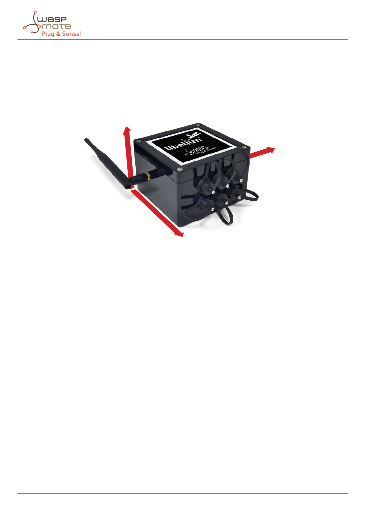
The EBM is specially designed to minimize its power consumption and maximizing its eciency and the energy
delivered to the node. This way, the internal electronic is in an ultra-low power state most of the time. The pictures
below show a general view of the EBM main parts.
Figure: External Battery Module
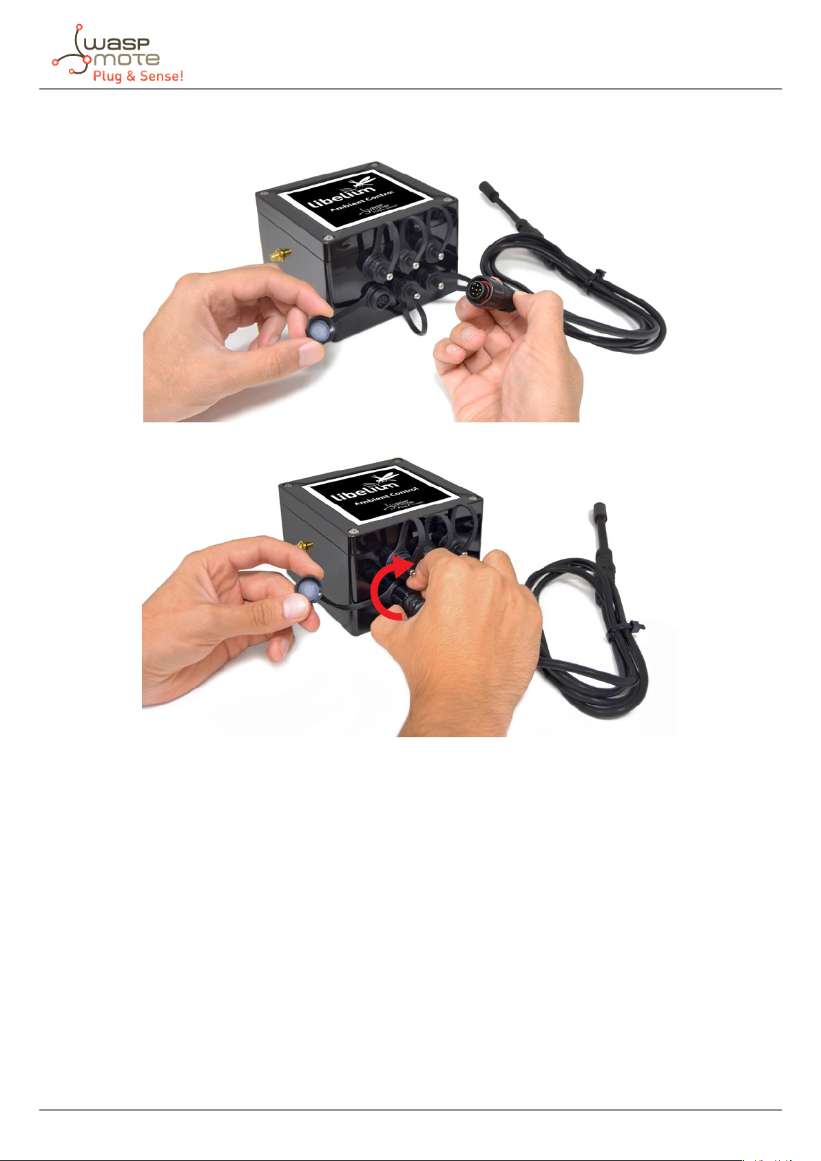
As shown above, the EBM has 2 sockets: One for the solar panel and one for the Plug & Sense! node. An extension
cord will be used to connect the EBM and the node.
-60- v8.6

External Battery Module
Figure: External Battery Module’s Plug & Sense! connector
Figure: Plug & Sense! with External Battery Module
A solar panel can be attached to the solar panel connector, providing extra energy to the Plug & Sense! and
extending the EBM life. Furthermore, if the charging period occurs while the solar panel is providing energy, the
EBM will only provide the necessary current to fulll the demand of the Plug & Sense! node. If the solar panel is
able to provide all the current demand, the EBM will not contribute during the charging process. This way, the
system does not waste energy from the solar panel and, at the same time, it enlarges the EBM battery lifetime.
-61- v8.6

Figure: External Battery Module with a solar panel connected
External Battery Module
Figure: Plug & Sense! with External Battery Module and solar panel
Finally, the EBM is compatible with all the Plug & Sense! product range, but it is not compatible with other Libelium
products like Meshlium, Smart Parking or MySignals.
-62- v8.6

External Battery Module
16.2. Operating modes
The EBM is designed to charge a Plug & Sense! node once per day during a preprogrammed period of time.
There is a latch button to turn on and o the EBM. This button also includes a red LED to show the user when the
device has started working. It will blink only a couple of times when the device is switched on, to avoid unnecessary
current consumption through it. When the device is on, the button will look like in the picture below.
Figure: External Battery Module, on position
Due to the nature of the EBM battery, its level cannot be monitored. If the LED does not blink when the button
is pressed, the EBM battery could be empty. On the other hand, when the button is o, the battery is physically
disconnected from any circuitry and there is no power consumption from the battery, even if there is a solar panel
present. Finally, the LED will not be on during the charging period for eciency purposes.
The External Battery Module has 3 operating modes. In order to select them, there is a 3-position rotative selector
switch.
Figure: External Battery Module operation selector
-63- v8.6

External Battery Module
The operating mode determines the daily time that the system will be charging a node:
• Position 1 will set the charging time to 5 minutes per day
• Position 2 will set the charging time to 15 minutes per day
• Position 3 will set the charging time to 30 minutes per day
During the charging period, the Plug & Sense! node will be recharged at the maximum charging current, which
is 300 mA. The operating mode must be selected before turning on the EBM. The selector will be read just after
turning on the device and the button LED will blink accordingly to the selected mode (one blink for position
1, 2 blinks for position 2 and so on). If the mode needs to be changed, it is necessary to turn o the EBM
rst, otherwise moving the selector will not have any eect. Moreover, it has to be taken into account that
temperature variations might induce small time drifts due to the tolerance of the internal electronic components.
Figure: Selector on the 3 dierent positions
If the Plug & Sense! charging current needs to be monitored, please use the example power 06: battery recharging.
The current ow trough the Plug & Sense! solar panel connector will be printed on screen. Besides, take into
account that the EBM will start the selected charging period 5 minutes after turning it on.
As can be inferred from the previous lines, the EBM battery life will be larger in position 1 than in position 3. To
estimate the battery life, consider that the maximum allowed charging current through the Plug & Sense! solar
panel connector is 300 mA (it becomes smaller when the Plug & Sense! battery is near to 100%). Moreover, take
into account that environmental conditions like temperature or the battery self-discharge may aect also to the
EBM lifetime.
-64- v8.6

Vent plug / Pressure Compensator
17. Vent plug / Pressure Compensator
The purpose of the Vent Plug is to avoid condensation by compensating external / internal pressure. Do not try to
connect anything to this element and also do not modify its position or any of its parts.
Figure: Vent plug of Waspmote Plug & Sense!
-65- v8.6

Antenna
18. Antenna
By default, Waspmote Plug & Sense! has one external antenna with a standard SMA connector. This connector
allows to connect the RF antenna. See next section for more information about other antenna options.
Figure: Antenna connector of the enclosure
To ensure good RF coverage, be sure that the antenna points to the sky and also be sure that the antenna is
screwed completely to the connector. To connect the antenna, just align it with the connector and screw it carefully.
Antenna must be always connected in order to ensure a good RF communication.
Figure: Connecting antenna to the enclosure
Note: Once Waspmote Plug & Sense! is installed, it is recommended to x it using a tape like the one shown in the picture
below.
-66- v8.6

Antenna
Figure: Recommended tape
Do not try to connect other kind of antennas which do not match with SMA standard connector and also other
antennas not provided by Libelium.
Figure: Ensure antenna remains in the right position
18.1. Antennas for the Plug & Sense! 4G model
The Waspmote Plug & Sense! models including a 4G radio will have 3 antenna connectors: the cellular main
antenna, the cellular diversity antenna and the GPS antenna (GPS receiver is only available in 4G EU/BR). The
antenna to be connected is the same on the 3 cases. See the pictures below to identify each 4G antenna connector.
The 3 or 2 antennas must be properly connected for the right operation of the 4G radio.
Figure: Main and GPS antennas (only 4G models)
-67- v8.6

Figure: Diversity antenna (only 4G models)
Antenna
Note: The 4G radios for Australia and for US do not have a GPS receiver, so in this case, only 2 antennas are provided.
Just leave the GPS antenna connector without any antenna.
18.2. Antennas for Plug & Sense! GPS-ready models
The Waspmote Plug & Sense! models including a GPS receiver will have 3 antenna connectors: the main radio
antenna connector, the GPS antenna connector and an unused antenna connector. The GPS antenna and the
main antenna are dierent. The GPS antenna is easy to identify: it is a square and magnetic antenna with a long
cable (2 m). See the pictures below to identify each GPS antenna connector.
Figure: Main and GPS antennas connectors (only GPS-ready models)
-68- v8.6

Figure: Not used antenna connector (only GPS-ready models)
Antenna
Note: In order to achieve a better performance and maximum satellite visibility, the GPS antenna should be placed in an
open-space location and oriented so that its reference arrow points vertically to the sky.
-69- v8.6

Sensor protection
19. Sensor protection
19.1. Special probes
There are some sensor probes which include special protection against sunlight and bad environmental
conditions. For instance, the temperature, humidity and pressure probe has a special lter which allows humidity
measurement but oers protection against water.
However, a lot of sensor probes include just a standard protection. If the nal application involves bad environmental
conditions and a lot of sunlight hours, Libelium suggests the usage of a solar radiation shield.
In addition, refer to corresponding section for more information about sensor probes.
20. Battery
Libelium provides a 6600 mA·h rechargeable battery inside Waspmote Plug & Sense!.
Waspmote has a control and safety circuit which makes sure the battery charge current is always adequate. The
following image shows a battery discharging for a typical load and for a specic case.
Figure: Typical discharging curve for the 6600 mA·h battery
Note: When recharging, if the battery is near 0%, it will take some time before the battery level increases.
Note: It is normal to see some battery level variations during the charging periods due to the Waspmote charging
circuitry. To know the real battery level of the node, it is recommended to measure it when the node is not being
recharged and also with sensors and radio modules switched o.
Note: The on/o button can be in on or o position to charge the battery.
-70- v8.6

Models
21. Models
There are some dened congurations of Waspmote Plug & Sense! depending on which sensors are going to be
used. Waspmote Plug & Sense! congurations allow to connect up to six sensor probes at the same time.
Each model takes a dierent conditioning circuit to enable the sensor integration. For this reason, each model
allows connecting just its specic sensors.
This section describes each model conguration in detail, showing the sensors which can be used in each case
and how to connect them to Waspmote. In many cases, the sensor sockets accept the connection of more than
one sensor probe. See the compatibility table for each model conguration to choose the best probe combination
for the application.
It is very important to remark that each socket is designed only for one specic sensor, so they are not
interchangeable. Always be sure you have connected the probes in the right socket. Otherwise, they can be
damaged.
Figure: Identication of sensor sockets
-71- v8.6

Models
21.1. Smart Environment PRO
The Smart Environment PRO model has been created as an evolution of Smart Environment. It enables the user
to implement pollution, air quality, industrial, environmental or farming projects with high requirements in terms
of high accuracy, reliability and measurement range as the sensors come calibrated from factory.
Figure: Smart Environment PRO Waspmote Plug & Sense! model
-72- v8.6

Sensor sockets are congured as shown in the gure below.
Models
Sensor
Socket
A, B, C or F
Sensor probes allowed for each sensor socket
Parameter Reference
Carbon Monoxide (CO) for low concentrations [Calibrated] 9371-LC-P
Carbon Dioxide (CO2) [Calibrated] 9372-P
Oxygen (O2) [Calibrated] 9373-P
Ozone (O3) [Calibrated] 9374-P
Nitric Oxide (NO) for low concentrations [Calibrated] 9375-LC-P
Nitric Dioxide (NO2) high accuracy [Calibrated] 9376-HA-P
Sulfur Dioxide (SO2) high accuracy [Calibrated] 9377-HA-P
Ammonia (NH3) for low concentrations [Calibrated] 9378-LC-P
Ammonia (NH3) for high concentrations [Calibrated] 9378-HC-P
Methane (CH4) and Combustible Gas [Calibrated] 9379-P
Hydrogen Sulde (H2S) [Calibrated] 9381-P
D
E
Figure: Sensor sockets configuration for Smart Environment PRO model
Note: For more technical information about each sensor probe go to the Development section on the Libelium website.
Calibrated gas sensors are manufactured once the order has been placed to ensure maximum durability of the
calibration feature. The manufacturing process and delivery may take from 4 to 6 weeks. The lifetime of calibrated
gas sensors is 6 months working at maximum accuracy. We strongly encourage our customers to buy extra gas
sensors to replace the original ones after that time to ensure maximum accuracy and performance.
Particle Matter (PM1 / PM2.5 / PM10) - Dust 9387-P
Temperature, humidity and pressure 9370-P
Luminosity (Luxes accuracy) 9325-P
Ultrasound (distance measurement) 9246-P
-73- v8.6

Models
21.2. Smart Security
The main applications for this Waspmote Plug & Sense! conguration are perimeter access control, liquid presence
detection and doors and windows openings. Besides, a relay system allows this model to interact with external
electrical machines.
Figure: Smart Security Waspmote Plug & Sense! model
Note: The probes attached in this photo could not match the nal location. See next table for the correct conguration.
-74- v8.6

Models
Sensor
Socket
Parameter Reference
Sensor probes allowed for each sensor socket
Temperature + Humidity + Pressure 9370-P
Luminosity (Luxes accuracy) 9325-P
Ultrasound (distance measurement) 9246-P
A, C, D or E
Presence - PIR 9212-P
Liquid Level (combustible, water) 9239-P, 9240-P
Liquid Presence (Point, Line) 9243-P, 9295-P
Hall Eect 9207-P
B Liquid Flow (small, medium, large) 9296-P, 9297-P, 9298-P
F Relay Input-Output 9270-P
Figure: Sensor sockets configuration for Smart Security model
As we see in the gure below, thanks to the directional probe, the presence sensor probe (PIR) may be placed in
dierent positions. The sensor can be focused directly to the point we want.
Figure: Configurations of the Presence sensor probe (PIR)
Note: For more technical information about each sensor probe go to the Development section on the Libelium
website.
-75- v8.6

Models
21.3. Smart Water
The Smart Water model has been conceived to facilitate the remote monitoring of the most relevant parameters
related to water quality. With this platform you can measure more than 6 parameters, including the most relevant
for water control such as dissolved oxygen, oxidation-reduction potential, pH, conductivity and temperature. An
extremely accurate turbidity sensor has been integrated as well.
The Smart Water Ions line is complementary for these kinds of projects, enabling the control of concentration
of ions like Ammonium (NH
Lithium (Li+), Magnesium (Mg2+), Nitrate (NO
+
), Bromide (Br-), Calcium (Ca2+), Chloride (Cl-), Cupric (Cu2+), Fluoride (F-), Iodide (I-),
4
-
), Nitrite (NO
3
-
), Perchlorate (ClO
2
-
), Potassium (K+), Silver (Ag+), Sodium
4
(Na+) and pH. Take a look to the Smart Water Ions line in the next section.
Refer to Libelium website for more information.
Figure: Smart Water Plug&Sense! model
-76- v8.6

Sensor sockets are congured as shown in the gure below.
Models
Sensor
Socket
A pH 9328
B Dissolved Oxygen (DO) 9327
C Conductivity 9326
E Oxidation-Reduction Potential (ORP) 9329
F
Figure: Sensor sockets configuration for Smart Water model
Note: For more technical information about each sensor probe go to the Development section on the Libelium
website.
Parameter Reference
Soil/Water Temperature 9255-P (included by default)
Turbidity 9353-P
Sensor probes allowed for each sensor socket
-77- v8.6

Models
21.4. Smart Water Xtreme
Smart Water Xtreme was created as an evolution of Smart Water. This model integrates high-end sensors, calibrated
in factory, with enhanced accuracy and performance. Their reduced recalibration requirements and robust design
enlarge maintenance periods, making it more aordable to deploy remote Smart Water applications. This line
includes a great combination of the most signicant water parameters like dissolved oxygen, pH, oxidation-
reduction potential, conductivity, salinity, turbidity, suspended solids, sludge blanket and temperature.
Refer to Libelium website for more information.
Figure: Smart Water Xtreme Waspmote Plug & Sense! model
-78- v8.6

Sensor sockets are congured as shown in the gure below.
Models
Sensor
A, B, C, D and E
A and D
Sensor probes allowed for each sensor socket
Parameter Reference
Optical dissolved oxygen and temperature
OPTOD
Titanium optical dissolved oxygen and
temperature OPTOD
pH, ORP and temperature PHEHT 9485-P
Conductivity, salinity and temperature C4E 9486-P
Inductive conductivity, salinity and
temperature CTZN
Turbidity and temperature NTU 9353-P
Suspended solids, turbidity, sludge blanket
and temperature MES5
Temperature, air humidity and pressure 9370-P
Luxes 9325-P
Ultrasound 9246-P
Manta+40 9495-P
Chlorophyll 72470
BGA 72471
9488-P
9489-P
9487-P
9490-P
Organic matter CDOM/FDOM 72472
F
Figure: Sensor sockets conguration for Smart Water Xtreme model
Note: For more technical information about each sensor probe go to the Development section on the Libelium
website.
Ammonium 72473
Nitrate 72474
Chloride 72475
Sodium 72476
Calcium 72477
-79- v8.6

Models
21.5. Smart Water Ions
The Smart Water Ions models specialize in the measurement of ions concentration for drinking water quality
control, agriculture water monitoring, swimming pools or waste water treatment.
The Smart Water line is complementary for these kinds of projects, enabling the control of parameters like
turbidity, conductivity, oxidation-reduction potential and dissolved oxygen. Take a look to the Smart Water line in
the previous section. Refer to Libelium website for more information.
There are 3 variants for Smart Water Ions: Single, Double and PRO. This is related to the type of ion sensor that
each variant can integrate. Next section describes each conguration in detail.
Figure: Smart Water Ions Waspmote Plug & Sense! model
-80- v8.6

Single
This variant includes a Single Junction Reference Probe, so it can read all the single type ion sensors.
Sensor sockets are congured as shown in the table below.
Models
Sensor
Socket
Parameter Reference
Sensor probes allowed for each sensor socket
Fluoride Ion (F-) 9353
Fluoroborate Ion (BF4-) 9354
A, B, C and D
Nitrate Ion (NO
-
) 9355
3
pH (for Smart Water Ions) 9363
E Single Junction Reference 9350 (included by default)
F Soil/Water Temperature 9255-P (included by default)
Figure: Sensor sockets conguration for Smart Water Ions model, single variant
Note: For more technical information about each sensor probe go to the Development section on the Libelium
website.
Double
This variant includes a Double Junction Reference Probe, so it can read all the double type ion sensors.
Sensor sockets are congured as shown in the table below.
Sensor
Socket
Parameter Reference
Sensor probes allowed for each sensor socket
Bromide Ion (Br-) 9356
Chloride Ion (Cl-) 9357
Cupric Ion (Cu2+) 9358
A, B, C and D
Iodide Ion (I-) 9360
Silver Ion (Ag+) 9362
pH (for Smart Water Ions) 9363
E
F
Figure: Sensor sockets conguration for Smart Water Ions model, double variant
Double Junction Reference 9351 (included by default)
Soil/Water Temperature 9255-P (included by default)
Note: For more technical information about each sensor probe go to the Development section on the Libelium
website.
-81- v8.6

Models
Pro
This special variant integrates extreme quality sensors, with better performance than the Single or Double lines.
In this case, there is only one type of reference probe and up to 16 dierent ion parameters can be analyzed in 4
sockets.
Sensor sockets are congured as shown in the table below.
Sensor
Socket
A, B, C or D
Sensor probes allowed for each sensor socket
Parameter Reference
Ammonium Ion (NH
+
) [PRO] 9412
4
Bromide Ion (Br-) [PRO] 9413
Calcium Ion (Ca2+) [PRO] 9414
Chloride Ion (Cl-) [PRO] 9415
Cupric Ion (Cu2+) [PRO] 9416
Fluoride Ion (F-) [PRO] 9417
Iodide Ion (I-) [PRO] 9418
Lithium Ion (Li+) [PRO] 9419
Magnesium Ion (Mg2+) [PRO] 9420
Nitrate Ion (NO
Nitrite Ion (NO
Perchlorate Ion (ClO
-
) [PRO] 9421
3
-
) [PRO] 9422
2
-
) [PRO] 9423
4
Potassium Ion (K+) [PRO] 9424
Silver Ion (Ag+) [PRO] 9425
Sodium Ion (Na+) [PRO] 9426
pH [PRO] 9411
E
F
Figure: Sensor sockets conguration for Smart Water Ions model, PRO variant
Reference Sensor Probe [PRO] 9410 (included by default)
Soil/Water Temperature 9255-P (included by default)
Note: For more technical information about each sensor probe go to the Development section on the Libelium
website.
-82- v8.6

Models
21.6. Smart Parking
The Smart Parking node allows to detect available parking spots by placing the node on the pavement. It works
with a radar sensor and a magnetic sensor which detect when a vehicle is present or not.
The node benets from LoRaWAN technology, getting ubiquitous coverage with few base stations. The device is
very optimized in terms of power consumption, resulting in a long battery life. Its small size and the robust and
surface-mount enclosure enables a fast installation, without the need of digging a hole in the ground. Finally, the
developer does not need to program the node, but just congure some key parameters. Remote management
and bidirectional communication allow to change parameters from the Cloud.
Figure: Smart Parking node
Note: There are specic documents for parking applications on the Libelium website. Refer to the Smart Parking
Technical Guide to see typical applications for this model and how to make a good installation.
Figure: Smart Parking application diagram
-83- v8.6

Models
21.7. Smart Agriculture PRO
The Smart Agriculture models allow to monitor multiple environmental parameters involving a wide range of
applications. It has been provided with sensors for air and soil temperature and humidity, solar visible radiation,
wind speed and direction, rainfall, atmospheric pressure, etc.
The main applications for this Waspmote Plug & Sense! model are precision agriculture, irrigation systems,
greenhouses, weather stations, etc. Refer to Libelium website for more information.
Figure: Smart Agriculture PRO Waspmote Plug & Sense! model
-84- v8.6

Sensor sockets are congured as shown in the gure below.
Models
Sensor
Socket
A Weather Station WS-3000 (anemometer + wind vane + pluviometer) 9256-P
B
C
D (digital
bus)
E
F (digital
bus)
Figure: Sensor sockets configuration for Smart Agriculture PRO model
Parameter Reference
Soil Moisture 1 9248-P, 9324-P, 9323-P
Solar Radiation (PAR) 9251-P
Ultraviolet Radiation 9257-P
Soil Moisture 3 9248-P, 9324-P, 9323-P
Dendrometers 9252-P, 9253-P, 9254-P
Soil Temperature (Pt-1000) 9255-P
Temperature + Humidity + Pressure 9370-P
Luminosity (Luxes accuracy) 9325-P
Ultrasound (distance measurement) 9246-P
Leaf Wetness 9249-P
Soil Moisture 2 9248-P, 9324-P, 9323-P
Temperature + Humidity + Pressure 9370-P
Luminosity (Luxes accuracy) 9325-P
Ultrasound (distance measurement) 9246-P
Sensor probes allowed for each sensor socket
* Ask Libelium Sales Department for more information.
Note: For more technical information about each sensor probe go to the Development section on the Libelium
website.
-85- v8.6

Models
21.8. Smart Agriculture Xtreme
The Plug & Sense! Smart Agriculture Xtreme is an evolution of our Agriculture line with a new selection of highend professional sensors. It allows to monitor multiple environmental parameters involving a wide range of
applications, from plant growing analysis to weather observation. There are sensors for atmospheric and soil
monitoring and plants health. Up to 33 sensors can be connected.
Figure: Smart Agriculture Xtreme Waspmote Plug & Sense! model
-86- v8.6

Sensor sockets are congured as shown in the gure below.
Models
Sensor
Socket
A and D
B
C
Sensor probes allowed for each sensor socket
Parameter Reference
Non-contact surface temperature measurement SI-411 9468-P
Leaf and ower bud temperature SF-421 9467-P
Soil oxygen level SO-411 9469-P
Conductivity, water content and soil temperature 5TE 9402-P
Conductivity, water content and soil temperature GS3 9464-P
Soil temperature and volumetric water content 5TM 9460-P
Soil water potential MPS-6 9465-P
Vapor pressure, humidity, temperature, and atmospheric
pressure in soil and air VP-4
Temperature, air humidity and pressure 9370-P
Luxes 9325-P
Ultrasound 9246-P
Non-contact surface temperature measurement SI-411 9468-P
Leaf and ower bud temperature SF-421 9467-P
Soil oxygen level SO-411 9469-P
Conductivity, water content and soil temperature 5TE 9402-P
Conductivity, water content and soil temperature GS3 9464-P
Soil temperature and volumetric water content 5TM 9460-P
Soil water potential MPS-6 9465-P
Vapor pressure, humidity, temperature, and atmospheric
pressure in soil and air VP-4
Leaf wetness Phytos 31 9466-P
Shortwave radiation SP-510 9470-P
Solar radiation (PAR) SQ-110 for Smart Agriculture Xtreme 9251-PX
Ultraviolet radiation SU-100 for Smart Agriculture Xtreme 9257-PX
4-20 mA type (generic) -
Non-contact surface temperature measurement SI-411 9468-P
Leaf and ower bud temperature SF-421 9467-P
Soil oxygen level SO-411 9469-P
Conductivity, water content and soil temperature 5TE 9402-P
Conductivity, water content and soil temperature GS3 9464-P
Soil temperature and volumetric water content 5TM 9460-P
Soil water potential MPS-6 9465-P
Vapor pressure, humidity, temperature, and atmospheric
pressure in soil and air VP-4
Dendrometers (DC2, DD-S, DF) for Smart Agriculture Xtreme 9252-PX, 9253-PX, 9254-PX
Shortwave radiation SP-510 9470-P
Solar radiation (PAR) SQ-110 for Smart Agriculture Xtreme 9251-PX
Ultraviolet radiation SU-100 for Smart Agriculture Xtreme 9257-PX
9471-P
9471-P
9471-P
-87- v8.6

Models
Shortwave radiation SP-510 9470-P
Solar radiation (PAR) SQ-110 for Smart Agriculture Xtreme 9251-PX
Ultraviolet radiation SU-100 for Smart Agriculture Xtreme 9257-PX
Weather station GMX-100 (PO) Probe 9472-P
Weather station GMX-101 (R) 9473-P
Weather station GMX-200 (W) 9474-P
Weather station GMX-240 (W-PO) 9463-P
Weather station GMX-300 (T-H-AP) 9475-P
E
F
Weather station GMX-301 (T-H-AP-R) 9476-P
Weather station GMX-400 (PO-T-H-AP) 9477-P
Weather station GMX-500 (W-T-H-AP) 9478-P
Weather station GMX-501 (W-T-H-AP-R) 9479-P
Weather station GMX-531 (W-PT-T-H-AP-R) 9480-P
Weather station GMX-541 (W-PO-T-H-AP-R) 9481-P
Weather station GMX-550 (W-x-T-H-AP) 9482-P
Weather station GMX-551 (W-x-T-H-AP-R) 9483-P
Weather station GMX-600 (W-PO-T-H-AP) 9484-P
Solar radiation and temperature Datasol MET probe 9496-P
Shortwave radiation SP-510 9470-P
Solar radiation (PAR) SQ-110 for Smart Agriculture Xtreme 9251-PX
Ultraviolet radiation SU-100 for Smart Agriculture Xtreme 9257-PX
RS-232 type (generic) -
4-20 mA type (generic) -
Figure: Sensor sockets configuration for Smart Agriculture model
Note: For more technical information about each sensor probe go to the Development section on the Libelium
website.z
-88- v8.6

Models
21.9. Ambient Control
This model is designed to monitor the main environment parameters easily. Only three sensor probes are allowed
for this model, as shown in next table.
Figure: Ambient Control Waspmote Plug & Sense! model
-89- v8.6

Sensor sockets are congured as it is shown in gure below.
Models
Sensor
Socket
Parameter Reference
Sensor probes allowed for each sensor socket
A Temperature + Humidity + Pressure 9370-P
B Luminosity (LDR) 9205-P
C Luminosity (Luxes accuracy) 9325-P
D, E and F Not used -
Figure: Sensor sockets configuration for Ambient Control model
As we see in the gure below, thanks to the directional probe, the Luminosity (Luxes accuracy) sensor probe may
be placed in dierent positions. The sensor can be focused directly to the light source we want to measure.
Figure: Configurations of the Luminosity sensor probe (luxes accuracy)
Note: For more technical information about each sensor probe go to the Development section on the Libelium
website.
-90- v8.6

Models
21.10. Smart Cities PRO
The main applications for this Waspmote Plug & Sense! model are noise maps (monitor in real time the acoustic
levels in the streets of a city), air quality, waste management, smart lighting, etc. Refer to Libelium website for
more information.
Figure: Smart Cities PRO Waspmote Plug & Sense! model
-91- v8.6

Sensor sockets are congured as shown in the gure below.
Models
Sensor
Socket
Noise level sensor NLS
A
B, C, and F
D Particle Matter (PM1 / PM2.5 / PM10) - Dust 9387-P
E
Temperature + Humidity + Pressure 9370-P
Luminosity (Luxes accuracy) 9325-P
Ultrasound (distance measurement) 9246-P
Carbon Monoxide (CO) for low concentrations
[Calibrated]
Carbon Dioxide (CO2) [Calibrated] 9372-P
Oxygen (O2) [Calibrated] 9373-P
Ozone (O3) [Calibrated] 9374-P
Nitric Oxide (NO) for low concentrations [Calibrated] 9375-LC-P
Nitric Dioxide (NO2) high accuracy [Calibrated] 9376-HA-P
Sulfur Dioxide (SO2) high accuracy [Calibrated] 9377-HA-P
Ammonia (NH3) for low concentrations [Calibrated] 9378-LC-P
Ammonia (NH3) for high concentrations [Calibrated] 9378-HC-P
Methane (CH4) and Combustible Gas [Calibrated] 9379-P
Hydrogen Sulde (H2S) [Calibrated] 9381-P
Hydrogen Chloride (HCl) [Calibrated] 9382-P
Temperature + Humidity + Pressure 9370-P
Luminosity (Luxes accuracy) 9325-P
Ultrasound (distance measurement) 9246-P
Temperature + Humidity + Pressure 9370-P
Luminosity (Luxes accuracy) 9325-P
Ultrasound (distance measurement) 9246-P
Sensor probes allowed for each sensor socket
Parameter Reference
9371-LC-P
Figure: Sensor sockets configuration for Smart Cities PRO model
Note: For more technical information about each sensor probe go to the Development section in Libelium website.
Calibrated gas sensors are manufactured once the order has been placed to ensure maximum durability of the
calibration feature. The manufacturing process and delivery may take from 4 to 6 weeks. The lifetime of calibrated
gas sensors is 6 months working at maximum accuracy. We strongly encourage our customers to buy extra gas
sensors to replace the original ones after that time to ensure maximum accuracy and performance.
-92- v8.6

Models
21.11. Radiation Control
The main application for this Waspmote Plug & Sense! conguration is to measure radiation levels using a Geiger
sensor. For this model, the Geiger tube is already included inside Waspmote, so the user does not have to connect
any sensor probe to the enclosure. The rest of the other sensor sockets are not used.
Figure: Radiation Control Waspmote Plug & Sense! model
Sensor sockets are not used for this model.
Note: For more technical information about each sensor probe go to the Development section on the Libelium
website.
-93- v8.6

Models
21.12. 4-20 mA Current Loop
The applications for this Plug & Sense! model are focused on adding wireless connectivity to 4-20 mA devices and
connecting them to the Cloud.
Figure: 4-20 mA Current Loop Waspmote Plug & Sense! model
Sensor sockets are congured as shown in the gure below.
Sensor
Socket
A Channel 1 (type 2 and type 3) 9270-P, DB9-P
B Channel 2 (type 2 and type 3) 9270-P, DB9-P
C Channel 3 (type 2 and type 3) 9270-P, DB9-P
D Channel 4 (type 4) 9270-P, DB9-P
Figure: Sensor sockets configuration for 4-20 mA Current Loop model
Note: For more technical information about each sensor probe go to the Development section on the Libelium website.
Board channel Reference
Sensor probes allowed for each sensor socket
-94- v8.6

Programming
22. Programming
Waspmote Plug & Sense! can be programmed using Libelium’s Integrated Development Environment (IDE).
For further details on how to install the Waspmote IDE and how to compile and upload your rst programs, we
advise to read the “Waspmote IDE: User Guide”. This guide contains step-by-step indications to get started; it can
be found on the Plug & Sense! Development section:
www.libelium.com/development/plug-sense/sdk_applications/
22.1. Real time Clock - RTC
Waspmote Plug & Sense! has a built-in Real Time Clock – RTC, which keeps it informed of the time. This allows to
program and perform time-related actions such as:
“Sleep for 1h 20 min and 15sec, then wake up and perform the following action..”
Or even programs to perform actions at absolute intervals, e.g.:
“Wake on the 5th of each month at 00:20 and perform the following action..”
All RTC programming and control is done through the I2C bus.
Alarms:
Alarms can be programmed in the RTC specifying day/hour/minute/second. That allows total control about when
the mote wakes up to capture sensor values and perform actions programmed on it. This allows Waspmote Plug
& Sense! to be in the saving energy mode (Deep Sleep) and makes it wake up just at the required moment.
As well as relative alarms, periodic alarms can be programmed by giving a time measurement, so that the node
reprograms its alarm automatically each time one event is triggered.
Waspmote Plug & Sense! can keep the RTC time correctly even if the on/o button is switched to o position.
RTC module has an internal compensation mechanism for the oscillation variations produced in the quartz crystal
by changes in temperature (Temperature Compensated Crystal Oscillator – TCXO).
The RTC is responsible for waking the node up from energy saving mode called Deep Sleep. In addition, it controls
when it has to wake up the node and perform a particular action.
All information about their programming and operation can be found in the RTC Programming Guide.
All the documentation is located in the Development section in the Libelium website.
-95- v8.6

Programming
22.2. Interruptions
Interruptions are signals received by the microcontroller which indicate it must stop the task it is doing to handle
an event that has just happened. Interruption control frees the microcontroller from having to control sensors all
the time. It also makes the sensors warn Waspmote Plug & Sense! when a determined value (threshold) is reached.
Waspmote Plug & Sense! is designed to work with two types of interruptions: Synchronous and asynchronous:
• Synchronous interruptions: They are scheduled by timers. They allow to program when we want them to be
triggered. There are two types of timer alarms: periodic and relative.
- Periodic alarms are those to which we specify a particular moment in the future, for example: “Alarm
programmed for every fourth day of the month at 00:01 and 11 seconds”. They are controlled by the RTC.
- Relative alarms are programmed taking into account the current moment, eg: “Alarm programmed
for 5 minutes and 10 seconds”. They are controlled through the RTC and the microcontroller’s internal
Watchdog.
• Asynchronous Interruptions: These are not scheduled, so it is not known when they will be triggered. Types:
- Sensors: The sensor boards can be programmed so that an alarm is triggered when a sensor reaches a
certain threshold.
- Accelerometer: The accelerometer can be programmed so that certain events such (as a fall or change of
direction) generate an interruption.
All interruptions, both synchronous and asynchronous can wake Waspmote Plug & Sense! up from the Sleep and
the Deep Sleep modes.
All information about the programming and operation of interruptions can be found in the Interruption
Programming Guide.
22.3. Watchdog
The ATmega1281 microcontroller inside the Waspmote Plug & Sense! has an internal Enhanced Watchdog Time
– WDT. The WDT precisely counts the clock cycles generated by a 128 kHz oscillator. The WDT generates an
interruption signal when the counter reaches the set value. This interruption signal can be used to wake the
microcontroller from the Sleep mode or to generate an internal alarm when it is running in on mode, which is very
useful when developing programs with timed interruptions.
The WDT allows the microcontroller to wake up from a low consumption Sleep mode by generating an interruption.
For this reason, this clock is used as a time-based alarm associated with the microcontroller’s Sleep mode. This
allows very precise control of small time intervals: 16 ms, 32 ms, 64 ms, 128 ms, 256 ms, 500 ms, 1 s, 2 s, 4 s, 8 s.
For intervals over 8 s (Deep Sleep mode), the RTC is used and not the microcontroller.
All information about their programming and operation can be found in the Interrupt Programming Guide.
All the documentation is located in the Development section in the Libelium website.
22.3.1. RTC Watchdog for reseting Waspmote
One of the alarms of the RTC (Alarm 2) is connected to a Watchdog reset circuit that is able to reset the
microcontroller of Waspmote Plug & Sense! when the alarm is generated. This Watchdog has been implemented
for reseting Waspmote Plug & Sense! if it gets stuck. That periodical reset avoids erratic behaviour. This is highly
recommended for applications that need to be very robust and can never stop working. The use of the Watchdog
feature ensures us that our Waspmote will never stop working.
The Watchdog feature requires the physical watchdog switch to be put in “enable” position (default state in
Waspmote Plug & Sense! Devices).
All information about the RTC programming and operation can be found in the RTC Programming Guide.
All the documentation is located in the Development section in the Libelium website.
-96- v8.6

Programming Cloud Service
23. Programming Cloud Service
The Programming Cloud Service is an intuitive graphic interface which creates code automatically. The user
just needs to ll a web form to obtain binaries for Plug & Sense!. Advanced programming options are available,
depending on the license selected.
Features:
• No more programming, just congure a web form and the PCS will create the binary
• Always up-to-date: code is compiled on the Cloud, with the latest libraries
• Advanced options: Water and Ions calibration, Watchdog, critical battery warning, GPS, Industrial Protocols,
HTTPS, encryption (at both payload and link levels), etc
• Template management
• New devices are added easily (bulk or individual activation codes)
• Simple devices management: list, order, search or lter
• Share your devices with others
• Three license types: Basic, PRO and Elite
• Easy licenses management
• Summary reports
• Just program any standard Plug & Sense! in minutes!
Check how easy it is to handle the Programming Cloud Service at:
https://cloud.libelium.com/
Figure: Programming Cloud Service
-97- v8.6

Uploading code
24. Uploading code
Using the USB connector, a new code can be uploaded to Waspmote without opening Waspmote Plug & Sense!.
Just connect one side of the USB cable to this connector, removing protection cap if necessary and connect the
other side to a PC. Remember that Waspmote must be on to allow uploading a new code. Next steps describe this
process in detail.
Step 1: Open the USB connector
Remove the protection cap of the USB connector.
Figure: Removing the USB cap
* n the case you have a Plug & Sense! with a 4G module, insert your nano-SIM card in the External SIM/USB socket with care.
Figure: Inserting a SIM card with care in the External SIM/USB socket
-98- v8.6

Uploading code
Step 2: Connect the USB cable to Waspmote Plug & Sense!
Connect one end of the provided male-to-male USB cable to the USB connector. For models with 4G module, a
micro-USB is supplied.
Figure: Connecting the USB cable to Waspmote Plug & Sense!
Step 3: Connect the USB cable to PC
Connect the other end of the USB cable to your PC.
Figure: Connecting the node to a PC
-99- v8.6

Step 4: Turn on Waspmote Plug & Sense!
Be sure you have turned on the node by pressing on/o button.
Uploading code
Figure: Turning on Waspmote
Step 5: Open Waspmote IDE
Now run Waspmote IDE on your PC. If you do not have Waspmote IDE already installed in your PC, then go to the
Development section of Libelium website to download the latest version; there is a dedicated guide to help in the
process: “Waspmote IDE: User Guide”.
If it is the rst time you plug a Waspmote Plug & Sense! on your PC and you are unable to see the proper USB port,
maybe you should install the latest FTDI drivers: http://www.ftdichip.com/Drivers/D2XX.htm
Moreover, if you have troubles installing FTDI drivers and your computer is unable to recognize Waspmote,
please follow the installation guide for your operating system on your next link: http://www.ftdichip.com/Support/
Documents/InstallGuides.htm
-100- v8.6
 Loading...