

Libelium Waspmote Plug & Sense! Series, Waspmote Plug & Sense! LoRaWAN US, Waspmote Plug & Sense! WiFi, Waspmote Plug & Sense! Sigfox US, Waspmote Plug & Sense! 900 US User Manual
...Page 1
Waspmote Plug & Sense!
User Manual
Page 2

-2-
Index
© Libelium Comunicaciones Distribuidas S.L.
INDEX
1. Introduction ......................................................................................................................................... 3
2. General and safety information ......................................................................................................... 3
3. Waspmote Plug & Sense!’s Hardware Setup ...................................................................................... 4
3.1. ON/OFF Button ............................................................................................................................................................................4
3.2. External LED ...................................................................................................................................................................................5
3.3. Resetting Waspmote Plug & Sense! with an external magnet ....................................................................................5
3.4. USB ....................................................................................................................................................................................................7
3.4.1. External SIM socket ......................................................................................................................................................8
3.5. Antenna ........................................................................................................................................................................................ 10
4. Waspmote IDE: Download and Installation ..................................................................................... 12
5. Compiling a New Program ................................................................................................................ 13
6. Uploading a New Program to Waspmote Plug & Sense! ................................................................. 15
7. Certications information ................................................................................................................ 21
7.1. USA and Canada certication .............................................................................................................................................. 21
Page 3

-3-
1. Introduction
The aim of this manual is to introduce the user to Waspmote Plug & Sense! in a practical way.
This document applies to the following Waspmote Plug & Sense! models, approved for FCC and IC:
Model FCC ID IC
Waspmote Plug & Sense! 802.15.4 XKM-WPS-2400-V1 8472A-WPS2400V1
Waspmote Plug & Sense! 900 US XKM-WPS-900-V1 8472A-WPS900V1
Waspmote Plug & Sense! WiFi XKM-WPS-WIFI-V1 8472A-WPSWIFIV1
Waspmote Plug & Sense! 4G US XKM-WPS-4G-V1 8472A-WPS4GV1
Waspmote Plug & Sense! LoRaWAN US XKM-WPS-LORA-V1 8472A-WPSLORAV1
Waspmote Plug & Sense! Sigfox US XKM-WPS-SFX-V1 8472A-WPSSFXV1
2. General and safety information
Software:
• Upload code only using Waspmote IDE. If a dierent IDE is used, Waspmote can be damaged and can become
unresponsive. This use is not covered under warranty.
• Do not unplug any connector while uploading code. Waspmote can become unresponsive. This use is not covered under
warranty.
• Do not connect or disconnect any connector while Waspmote is ON. Waspmote can become unstable or unresponsive,
and internal parts can be damaged. This fact is not covered under warranty.
Hardware:
• Do not handle black stickers seals on both sides of the enclosure (Warranty stickers). Their integrity is the proof that
Waspmote Plug & Sense! has not been opened. If they have been handled, damaged or broken, the warranty is void.
• Do not open Waspmote Plug & Sense! in any case. This will automatically make the warranty void.
• Do not handle the four metallic screws of Waspmote Plug & Sense!. They ensure waterproof seal.
• Do not submerge Waspmote Plug & Sense! in liquids.
• Do not place nodes on places or equipment where it could be exposed to shocks and/or big vibrations.
• Do not expose Waspmote Plug & Sense! to temperatures below -10ºC or above 50ºC.
• Do not try to extract, screw, break or move Waspmote Plug & Sense! connectors far from necessary usage, waterproof
sealing can be damaged and warranty will be voided. For more information: http://www.libelium.com
• Do not connect any sensor not provided by Libelium.
• Do not place Waspmote Plug & Sense! where water can reach internal parts of sensors.
Page 4
-4-
3. Waspmote Plug & Sense!’s Hardware Setup
Here we show the most basic points about the hardware conguration:
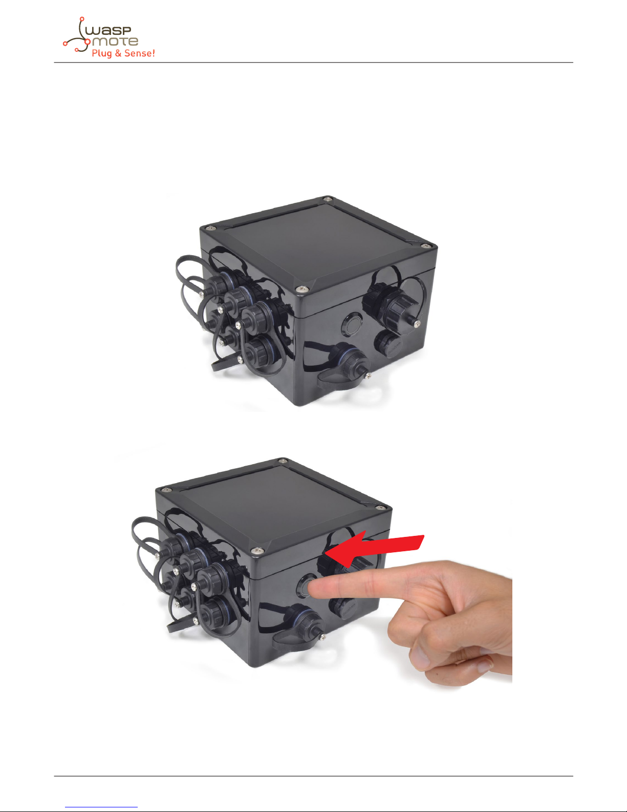
3.1. ON/OFF Button
This button is used to turn ON or OFF Waspmote. It is a latch type button with two static positions as shown below. In ON
position, the button remains a bit lower than LED ring.
Figure : On / O button at o position
Figure : Turning On Waspmote
Page 5
-5-
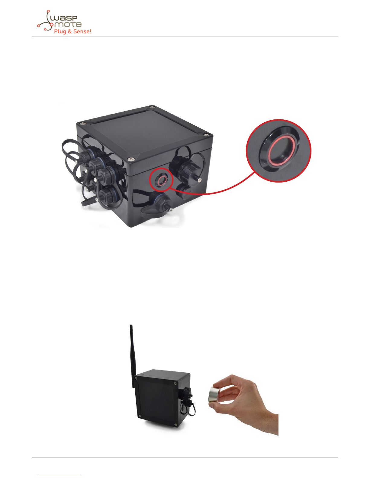
3.2. External LED
ON / OFF button includes a red ring led, which can be managed by software. This led can be used for instance to know that
Waspmote is ON, or for debugging purposes at developing phase. By default, Waspmote Plug & Sense! comes with a code that
blinks briey (3 times in less than one second) this led when it is turned ON. The LED can be managed specifying ON time or
just setting this state with specic API functions. The user should take into account that the usage of this led will increase power
consumption due to external LED consumes 4.4 mA.
Figure : Waspmote turned On
3.3. Resetting Waspmote Plug & Sense! with an external magnet
Waspmote Plug & Sense! it can be reset with an external magnet, with no contact. If one node stops working or if a defective
behavior is detected, it would be costly to uninstall the node to bring it back to laboratory. This feature allows the network
manager to reset the node in a quick and easy way.
The hardware consists of a reed switch connected to the Waspmote reset line. When the user gets the magnet close to the reedswitch, the reset is activated. When the user moves the magnet away, the reset line is released (the external LED will blink) and
Waspmote executes the bootloader rst and then, the setup function. After the setup, it will continue with the loop function.
Next pictures shows the right way to reset the node using an external magnet, rst moving it closer, and then moving it away.
Figure : Moving the magnet closer to the node.
Page 6
-6-
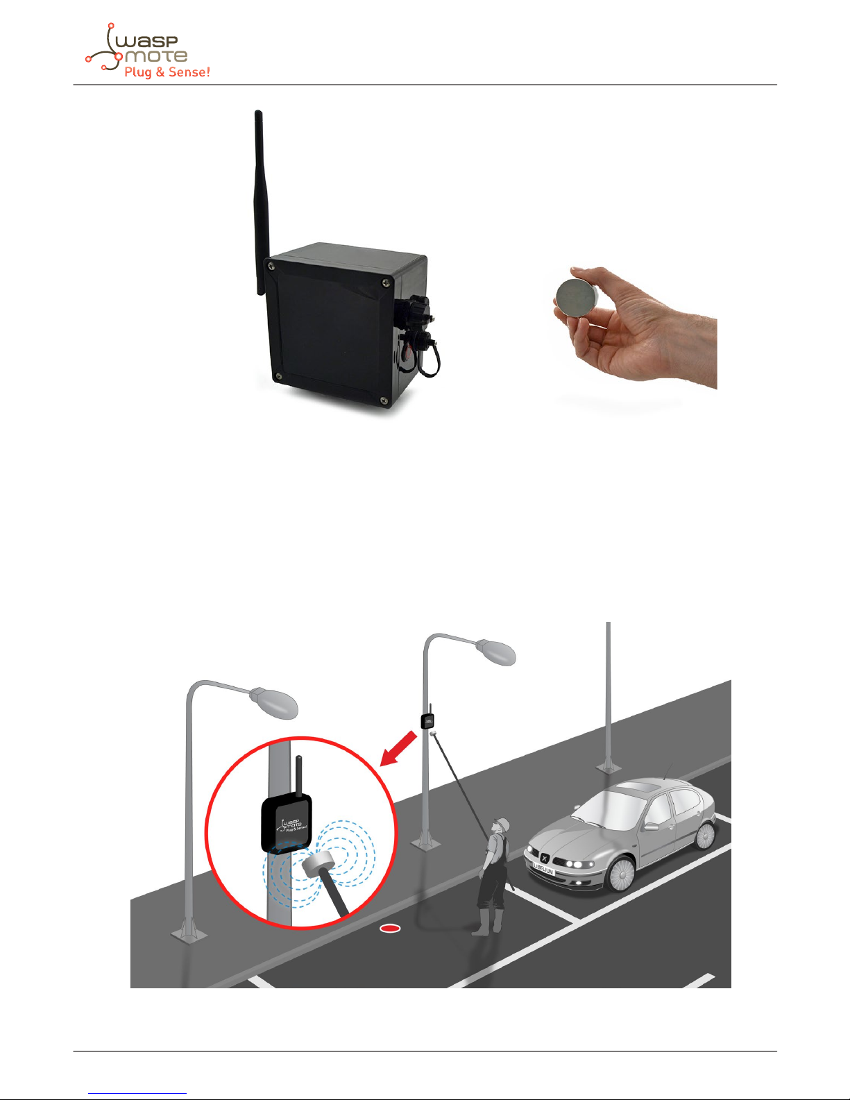
Figure : Moving the magnet away from the node.
The magnet is made of neodymium. It is a special, high-power magnet. We only advise to use the magnet Libelium provides.
It is not mandatory, but highly recommended to consider this feature when designing the project. The user should design the
software in a way the node can be reset if things go wrong. Remember that laboratory tests are always needed to validate the
feature before your nal deployment.
When the node is already deployed in the eld, and for instance it is installed in a trac light, this feature can be used to reset
the node easily, as it is shown in the diagram below, where a technician uses a pole with the magnet attached in one side.
Figure : Applying the magnet in a real deployment
Page 7
-7-
3.4. USB
This connector is used to upload code into Waspmote with a male to male USB cable provided by Libelium. Just connect one
side of the cable to this connector, removing protection cap and connect the other side to a PC to upload a code. Next picture
shows an example.
Figure : USB connector and protective cap
Figure : Connecting the USB cable to Waspmote
When uploading processes are nished, do not forget to screw rmly the protection cap to avoid connector damage.
Page 8

-8-
3.4.1. External SIM socket
The External SIM socket replaces the USB socket in two devices:
• Waspmote Plug & Sense! 4G
• Meshlium
The External SIM socket is composed of 2 connectors:
• micro-SIM card
• micro-USB (type B)
Figure : External SIM socket in a Plug & Sense! 4G
The operation with the micro-USB socket is just the same than with the normal USB socket. Just remember to use a micro-USB
cable.
Figure : Connecting the micro-USB cable to Plug & Sense! 4G
Page 9

-9-
The micro-SIM card connector allows the user to connect the SIM card he likes from the outside. You can ask your
telecommunication provider for a micro-SIM card. Alternatively you can take a normal SIM card and transform it into a microSIM card with a SIM card cutter.
Besides, the micro-SIM card connector has a push-pull mechanism, so it is really easy to remove the card with the aid of one nail.
Figure : Push-pull mechanism in the External SIM socket
It is highly important to turn o the Plug & Sense! device in a secure way before inserting a micro-SIM card, or removing an
existing SIM-card. The user can damage the device if this operation is done “on-the-y”.
Make sure you closed the External SIM socket with its protection cap before outdoors deployment.
Take into account that the External SIM socket has a limited resistance so please be gentle and do not push too hard with the
USB or SIM card.
Figure : Inserting a SIM card with care in the External SIM socket
Page 10

-10-
3.5. Antenna
By default Waspmote Plug & Sense! has one external antenna with a standard reverse polarized SMA connector. This connector
allows to connect the RF antenna.
Figure : Antenna connector of the enclosure
To ensure good RF coverage, be sure antenna points to the sky and also be sure antenna is screwed completely to the connector.
To connect the antenna, just align it with the connector and screw it carefully. Antenna must be connected in order to ensure
RF communication.
Figure : Connecting antenna to the enclosure
Note: Once Waspmote Plug & Sense! is installed, it is recommended to x it using a tape like the one shown in the picture below.
Page 11

-11-
Figure : Recommended tape Figure : Ensure antenna remains in the right position
Do not try to connect other kind of antennas which do not match with SMA RP standard connector and also other antennas not
provided by Libelium.
Waspmote Plug & Sense! 4G is a special case because it has 3 connectors for 3 antennas:
• Cellular communications (main)
• Cellular communications (receiver diversity, secondary antenna)
• GPS signal receiver
The 3 antennas are just the same model. You can see how to connect the 3 antennas in the following gure:
Figure : The 3 antennas of Waspmote Plug & Sense! 4G
Page 12

-12-
4. Waspmote IDE: Download and Installation
The rst step is to install the Waspmote IDE (Integrated Development Environment).
This IDE can be found on:
http://www.libelium.com/development/plug_&_sense/sdk_and_applications
The Waspmote IDE is based on the open source Arduino platform compiler, following the same style of libraries and operation.
It is important to use the version found on Libelium website and no other version of Arduino IDE. This is because the version
available on the Libelium website has been properly tested and for which we can assure optimum operation.
Page 13

-13-
5. Compiling a New Program
To use the Waspmote IDE compiler we must run the executable script called ‘Waspmote’, which is in the folder where the
compiler has been installed.
Waspmote IDE is divided into 4 main parts which can be seen in the following gure.
IDE options
Buttons: opening and
uploading codes
Main Code
Output messages
Figure : IDE – Waspmote parts
• The rst part is the menu which allows conguration of general parameters such as the selected serial port.
• The second part is a button menu which allows compilation, opening, saving or loading the selected code on the board.
• The third part contains the main code which will load in Waspmote and the fourth part shows us the possible compilation
and load errors, as well as the success messages if the process is carried out correctly.
The Waspmote IDE buttons panel allows certain functions to be carried out such as opening a previously saved code, creating a
new one or loading the code on the board. The following gure shows the panel and the functions of each button.
Page 14

-14-
Figure : IDE – Waspmote panel of buttons
The next step is to congure the folder where the created programs are going to be saved. In the Waspmote IDE, this folder is
called ‘sketchbook’ and can be congured by accessing the ‘File/Preferences’ tab. Clicking on this tab will open a new window
where the location of the sketchbook can be indicated. Once the sketchbook folder path is indicated, the downloaded test
program must be saved in this folder.
Waspmote IDE must be closed so that the changes and the newly saved program in the sketchbook folder are reected.
Page 15

-15-
6. Uploading a New Program to Waspmote Plug & Sense!
Using the USB connector, a new code can be uploaded to Waspmote without opening Waspmote Plug & Sense!. Just connect
one side of the USB cable to this connector, removing protection cap if necessary and connect the other side to a PC. Remember
that Waspmote must be ON to allow uploading a new code. Next steps describe this process in detail.
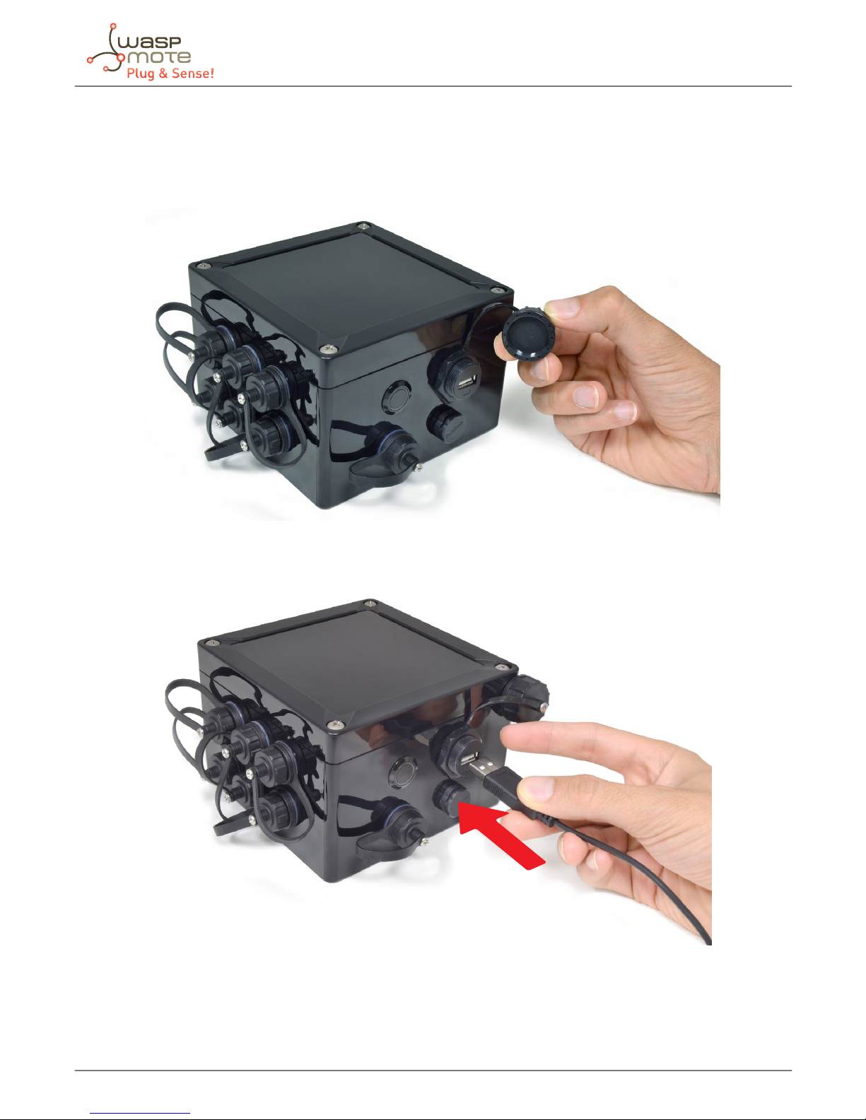
Step 1: Open the USB connector
Remove the protection cap of the USB connector.
Figure : Removing the USB cap
* In the case you have a Plug & Sense! 4G, insert your micro-SIM card in the External SIM socket with care.
Figure : Inserting a SIM card with care in the External SIM socket
Page 16

-16-
Step 2: Connect the USB cable to Waspmote Plug & Sense!
Connect one side of the male-to-male USB cable to the USB connector. For models with 4G, use a micro-USB cable.
Figure : Connecting the USB cable to Waspmote Plug & Sense!
Page 17

-17-
Step 3: Connect the USB cable to the PC
Connect the other side of the USB cable to your PC.
Figure : Connecting the node to a PC
Step 4: Turn On Waspmote Plug & Sense!
Be sure you have turned ON the node by pressing ON/OFF button.
Figure : Turning ON Waspmote
Step 5: Open Waspmote IDE
Now open Waspmote IDE. If you do not have Waspmote IDE already installed in your PC, then go to the Development section
of Libelium website to download it.
Page 18
-18-
Step 6: Select the corresponding code
Build your own code for your model using the online Code Generator (http://www.libelium.com/development/waspmote/
code_generator) provided by Libelium at the Development section of Libelium website (see corresponding section for details
about how to use the code generator). Download and open it in Waspmote IDE Plug & Sense!.
Save the sketch (Waspmote IDE has a button for that), for example with the name “Waspmote_Plug_Sense_test_code”,
and check the IDE message “Done Saving”
Figure : Preparing code for Waspmote Plug & Sense!
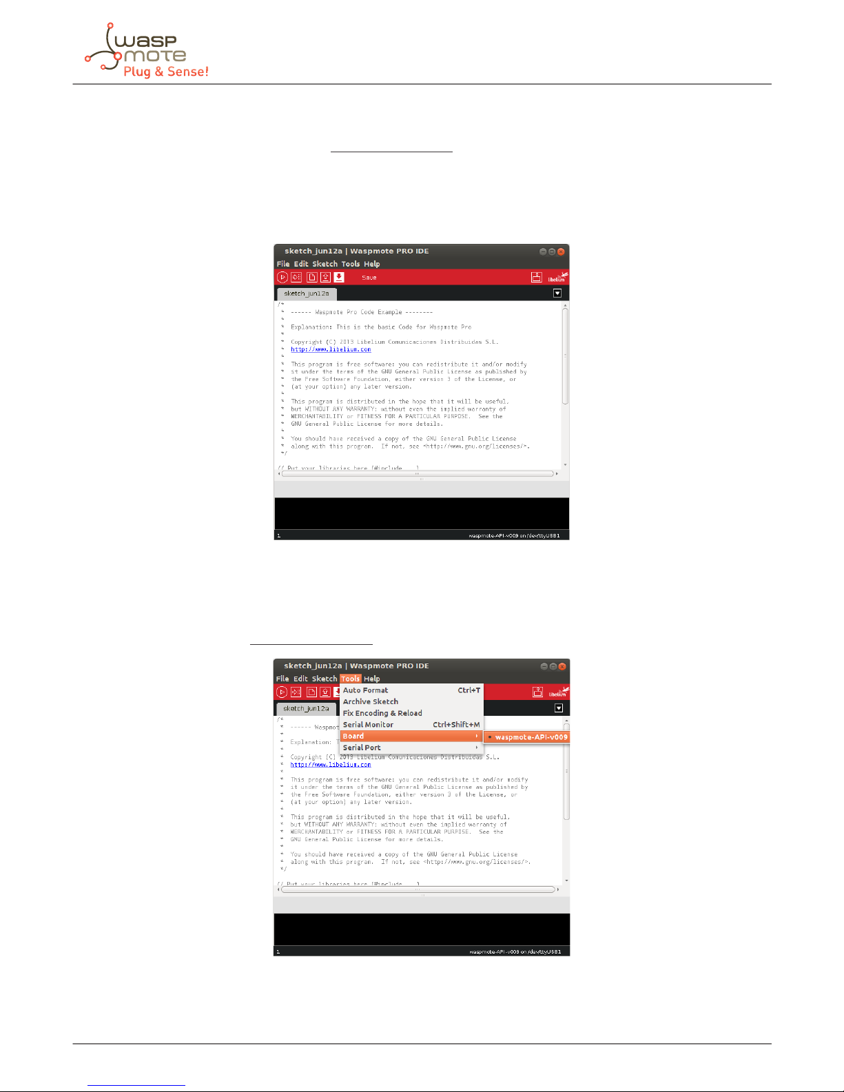
Step 7: Select the corresponding API
Select the API version corresponding to Waspmote Plug & Sense! going to tools/board. If you do not have the API for Waspmote
Plug & Sense!, please go to the Development section of Libelium website and download it.
Figure : Selecting API for Waspmote Plug & Sense!
Page 19

-19-
Step 8: Select the USB port
Select the corresponding serial port by going to tools/serial port. If you are unable to see the proper USB port maybe you should
install the latest FTDI drivers on your PC.
Figure : Selecting the USB port for Waspmote Plug & Sense!
Note: the name of the USB ports depends on the OS and the particular PC you have. The best way to nd the USB where Waspmote is
connected is trial & error.
Step 9: Compile the code
Compile the code (the IDE has a button for that), and check there are no errors or warnings. The IDE should say “Done Compiling”.
Figure : Compiling a code for Waspmote Plug & Sense!
Page 20

-20-
Step 10: Upload the code
Now, press the upload button and see messages coming out from IDE. During a while you will see message “uploading to I/O
board”.
Figure : Uploading a code for Waspmote Plug & Sense!
Wait a few seconds until the process ends and check there are no error messages, just “Done uploading” message.
Step 11: Open the Serial Monitor
If uploading processes are successfully completed, open Serial Monitor to see the output of the uploaded code.
Figure : Opening Waspmote IDE serial monitor
When uploading processes are nished successfully, do not forget to screw the protection cap of USB connector to avoid its
damage.
Page 21

-21-
7. Certications information
This document applies to the following Waspmote Plug & Sense! models, approved for FCC and IC:
Model FCC ID IC
Waspmote Plug & Sense! 802.15.4 XKM-WPS-2400-V1 8472A-WPS2400V1
Waspmote Plug & Sense! 900 US XKM-WPS-900-V1 8472A-WPS900V1
Waspmote Plug & Sense! WiFi XKM-WPS-WIFI-V1 8472A-WPSWIFIV1
Waspmote Plug & Sense! 4G US XKM-WPS-4G-V1 8472A-WPS4GV1
Waspmote Plug & Sense! LoRaWAN US XKM-WPS-LORA-V1 8472A-WPSLORAV1
Waspmote Plug & Sense! Sigfox US XKM-WPS-SFX-V1 8472A-WPSSFXV1
7.1. USA and Canada certication
Modication statement
Libelium has not approved any changes or modications to this device by the user. Any changes or modications could void the
user’s authority to operate the equipment.
Interference statement
This device complies with Part 15 of the FCC Rules and Industry Canada license-exempt RSS standard(s). Operation is subject
to the following two conditions: (1) this device may not cause interference, and (2) this device must accept any interference,
including interference that may cause undesired operation of the device.
Wireless notice
This device complies with FCC/ISED radiation exposure limits set forth for an uncontrolled environment and meets the FCC
radio frequency (RF) Exposure Guidelines and RSS‐102 of the ISED radio frequency (RF) Exposure rules. This transmitter must not
be co-located or operating in conjunction with any other antenna or transmitter.
For FCC Part 15 – Class B device: digital device or peripheral
This equipment has been tested and found to comply with the limits for a Class B digital device, pursuant to part 15 of the
FCC Rules. These limits are designed to provide reasonable protection against harmful interference in a residential installation.
This equipment generates, uses and can radiate radio frequency energy and, if not installed and used in accordance with the
instructions, may cause harmful interference to radio communications. However, there is no guarantee that interference will not
occur in a particular installation. If this equipment does cause harmful interference to radio or television reception, which can
be determined by turning the equipment o and on, the user is encouraged to try to correct the interference by one or more
of the following measures:
• Reorient or relocate the receiving antenna.
• Increase the separation between the equipment and receiver.
• Connect the equipment into an outlet on a circuit dierent from that to which the receiver is connected.
• Consult the dealer or an experienced radio/TV technician for help.
Modication statement
Libelium n’approuve aucune modication apportée à l’appareil par l’utilisateur, quelle qu’en soit la nature. Tout changement ou
modication peuvent annuler le droit d’utilisation de l’appareil par l’utilisateur.
Interference statement
Le présent appareil est conforme aux CNR d’Industrie Canada applicables aux appareils radio exempts de licence. L’exploitation
est autorisée aux deux conditions suivantes : (1) l’appareil ne doit pas produire de brouillage, et (2) l’utilisateur de l’appareil
doit accepter tout brouillage radioélectrique subi, même si le brouillage est susceptible d’en compromettre le fonctionnement.
Page 22

-22-
Wireless notice
Le présent appareil est conforme à l’exposition aux radiations FCC / ISED dénies pour un environnement non contrôlé et
répond aux directives d’exposition de la fréquence de la FCC radiofréquence (RF) et RSS‐102 de la fréquence radio (RF) ISED
règles d’exposition. L’émetteur ne doit pas être colocalisé ni fonctionner conjointement avec à autre antenne ou autre émetteur.
CAN ICES-3 (B) / NMB-3 (B)
This Class B digital apparatus complies with Canadian ICES-003.
Cet appareil numérique de classe B est conforme à la norme canadienne NMB-003.
 Loading...