

Page 1
Waspmote LoRaWAN
Networking Guide
Page 2

Index
Document Version: v7.6 - 10/2019
© Libelium Comunicaciones Distribuidas S.L.
INDEX
1. Introduction ..........................................................................................................................5
1.1. Technology overview ........................................................................................................................ 9
2. Hardware .............................................................................................................................10
2.1. Specications ................................................................................................................................... 10
2.1.1. LoRaWAN EU ........................................................................................................................10
2.1.2. LoRaWAN US ........................................................................................................................11
2.1.3. LoRaWAN AU .......................................................................................................................12
2.1.4. LoRaWAN IN ........................................................................................................................13
2.1.5. LoRaWAN ASIA-PAC / LATAM ............................................................................................14
2.1.6. LoRaWAN JP / KR ................................................................................................................15
2.2. Region standards ............................................................................................................................ 16
2.3. Power consumption........................................................................................................................ 17
2.3.1. LoRaWAN EU ........................................................................................................................17
2.3.2. LoRaWAN US ........................................................................................................................17
2.3.3. LoRaWAN AU ........................................................................................................................17
2.3.4. LoRaWAN IN .........................................................................................................................17
2.3.5. LoRaWAN ASIA-PAC / LATAM .............................................................................................18
2.3.6. LoRaWAN JP / KR .................................................................................................................18
2.4. Time consumption .......................................................................................................................... 19
2.5. How to connect the module .......................................................................................................... 19
2.6. Expansion Radio Board .................................................................................................................. 20
3. Software ............................................................................................................................... 22
3.1. Waspmote libraries ......................................................................................................................... 22
3.1.1. Waspmote LoRaWAN les ..................................................................................................22
3.1.2. Class constructor .................................................................................................................22
3.1.3. API constants .......................................................................................................................22
3.1.4. API variables .........................................................................................................................23
3.1.5. API functions ........................................................................................................................24
3.2. Module system management features ........................................................................................ 25
3.2.1. Switch on ..............................................................................................................................25
3.2.2. Switch o ..............................................................................................................................26
3.2.3. Module software reset........................................................................................................26
3.2.4. Module factory reset ...........................................................................................................26
3.2.5. Preprogrammed unique identier (EUI) ...........................................................................26
3.3. LoRaWAN parameters .................................................................................................................... 27
-2-
v7.6
Page 3

Index
3.3.1. Device EUI .............................................................................................................................27
3.3.2. Device address.....................................................................................................................27
3.3.3. Application Session Key ......................................................................................................28
3.3.4. Network session key ...........................................................................................................29
3.3.5. Application EUI.....................................................................................................................30
3.3.6. Application key ....................................................................................................................30
3.4. LoRaWAN module activation ......................................................................................................... 31
3.4.1. Over-The-Air Activation (OTAA) ..........................................................................................31
3.4.2. Activation By Personalization (ABP) ..................................................................................31
3.4.3. Join a network ......................................................................................................................31
3.5. LoRaWAN mode features ............................................................................................................... 33
3.5.1. Operational ISM bands .......................................................................................................33
3.5.2. Send data to a LoRaWAN gateway ....................................................................................33
3.5.3. Receiving data from a LoRaWAN gateway .......................................................................35
3.5.4. Save conguration ..............................................................................................................36
3.5.5. Power level ...........................................................................................................................37
3.5.6. Adaptive data rate (ADR) ....................................................................................................39
3.5.7. Data rate ...............................................................................................................................40
3.5.8. Transmission retries ...........................................................................................................41
3.5.9. Receiving windows ..............................................................................................................41
3.5.10. Automatic reply (AR) .........................................................................................................42
3.5.11. Uplink counter ...................................................................................................................43
3.5.12. Downlink counter ..............................................................................................................43
3.5.13. Channel parameters .........................................................................................................44
3.5.14. Duty cycle prescaler ..........................................................................................................50
3.5.15. Margin.................................................................................................................................50
3.5.16. Gateway number ...............................................................................................................50
3.6. P2P mode – Direct communication between nodes .................................................................. 50
3.6.1. Enable P2P mode ................................................................................................................50
3.6.2. Send data .............................................................................................................................51
3.6.3. Receive data .........................................................................................................................51
3.6.4. Power level ...........................................................................................................................51
3.6.5. Spreading Factor .................................................................................................................52
3.6.6. Frequency deviation............................................................................................................52
3.6.7. Preamble length ..................................................................................................................52
3.6.8. CRC header ..........................................................................................................................53
3.6.9. Coding Rate ..........................................................................................................................53
3.6.10. Bandwidth ..........................................................................................................................53
3.6.11. Frequency ...........................................................................................................................54
3.6.12. Signal to noise ratio (SNR) ................................................................................................54
3.7. Hybrid LoRaWAN / P2P mode ....................................................................................................... 55
4. LoRaWAN back-ends ...........................................................................................................56
4.1. Waspmote recommended conguration ..................................................................................... 56
-3- v7.6
Page 4

Index
4.1.1. LoRaWAN EU ........................................................................................................................56
4.1.2. LoRaWAN US ........................................................................................................................56
4.1.3. LoRaWAN AU ........................................................................................................................57
4.1.4. LoRaWAN IN .........................................................................................................................57
4.1.5. LoRaWAN ASIA-PAC / LATAM .............................................................................................57
4.1.6. LoRaWAN JP / KR .................................................................................................................58
4.2. Actility ............................................................................................................................................... 59
4.2.1. Device registration ..............................................................................................................59
4.2.2. Waspmote programming ...................................................................................................61
4.3. LORIOT ............................................................................................................................................. 62
4.3.1. Device registration ..............................................................................................................62
4.3.2. Data downlink ......................................................................................................................64
4.3.3. Waspmote programming ...................................................................................................64
4.4. The Things Network ........................................................................................................................ 65
5. When is LoRaWAN recommended? ...................................................................................66
6. Certications ....................................................................................................................... 67
7. Code examples and extended information .....................................................................68
8. API changelog ...................................................................................................................... 76
9. Documentation changelog ................................................................................................77
-4-
v7.6
Page 5
Introduction
1. Introduction
This guide explains the LoRaWAN modules features and functions. These products were designed for Waspmote
v12 and Plug & Sense! v12 and continue with no changes for Waspmote v15 and Plug & Sense! v15. There are
no great variations in this library for our new product lines Waspmote v15 and Plug & Sense! v15, released on
October 2016.
Anyway, if you are using previous versions of our products, please use the corresponding guides, available on our
Development website.
You can get more information about the generation change on the document “New generation of Libelium product
lines”.
The Libelium LoRaWAN module has been integrated into the main sensor lines Waspmote OEM and Plug & Sense!,
so now you can create your own Low Power Wide Area Network (LPWAN).
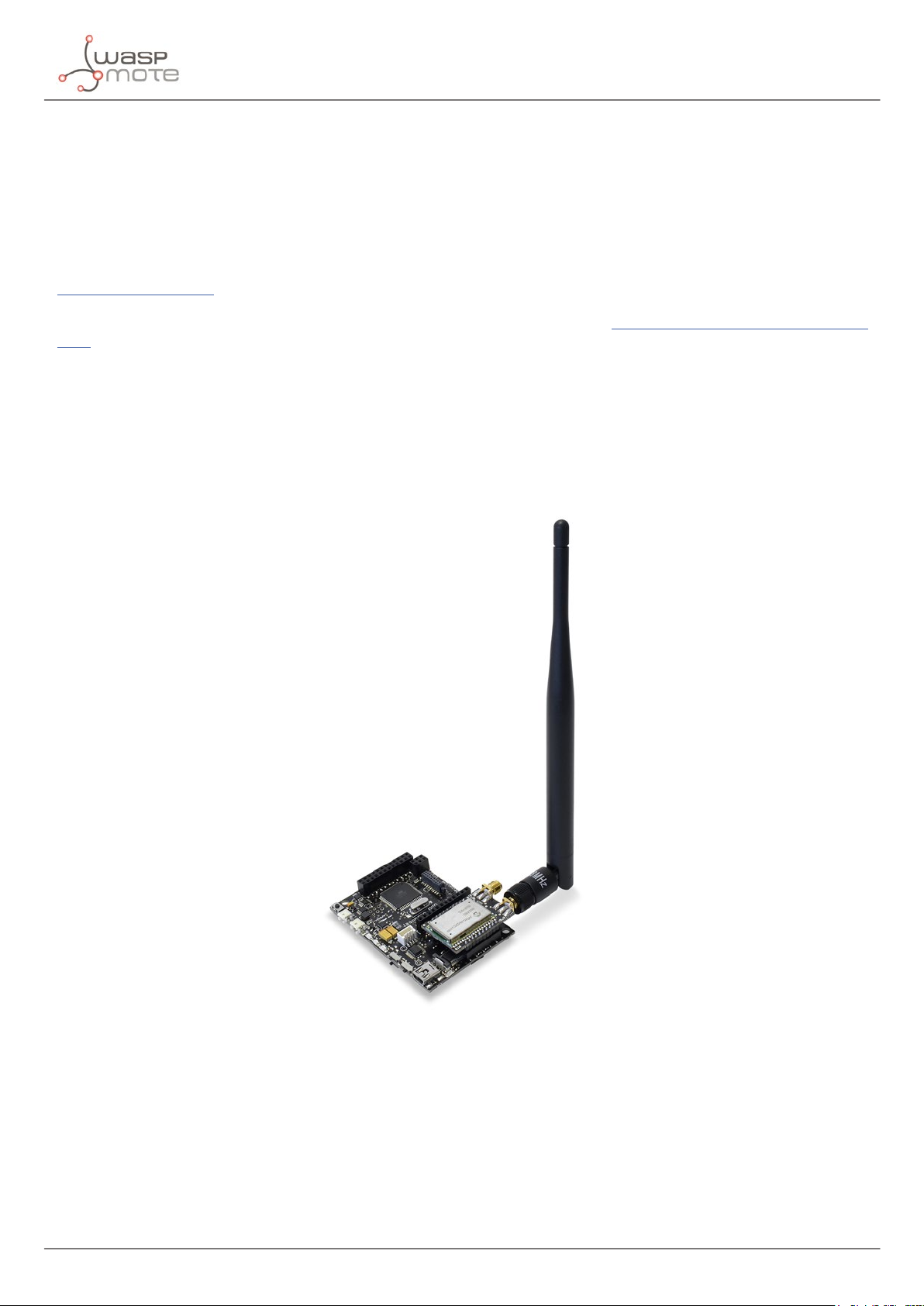
LoRaWAN is a new, private and spread-spectrum modulation technique which allows sending data at extremely low
data-rates to extremely long ranges. The low data-rate (down to few bytes per second) and LoRaWAN modulation
lead to very low receiver sensitivity (down to -136 dBm), which combined to an output power of +14 dBm means
extremely large link budgets: up to 150 dB, what means more than 22 km (13.6 miles) in LOS links and up to 2
km (1.2 miles) in NLOS links in urban environment (going through buildings).
Figure: Waspmote LoRaWAN
Libelium’s LoRaWAN EU/433 module works in both 868 and 433 MHz ISM bands and the LoRaWAN US module
works in 900 MHz ISM band, which makes them suitable for virtually any country. Those frequency bands are
lower than the popular 2.4 GHz band, so path loss attenuation is better in LoRaWAN. In addition, 433, 868 and
900 MHz are bands with much fewer interference than the highly populated 2.4 GHz band. Besides, these low
frequencies provide great penetration in possible materials (brick walls, trees, concrete), so these bands get less
loss in the presence of obstacles than higher bands.
-5- v7.6
Page 6
Introduction
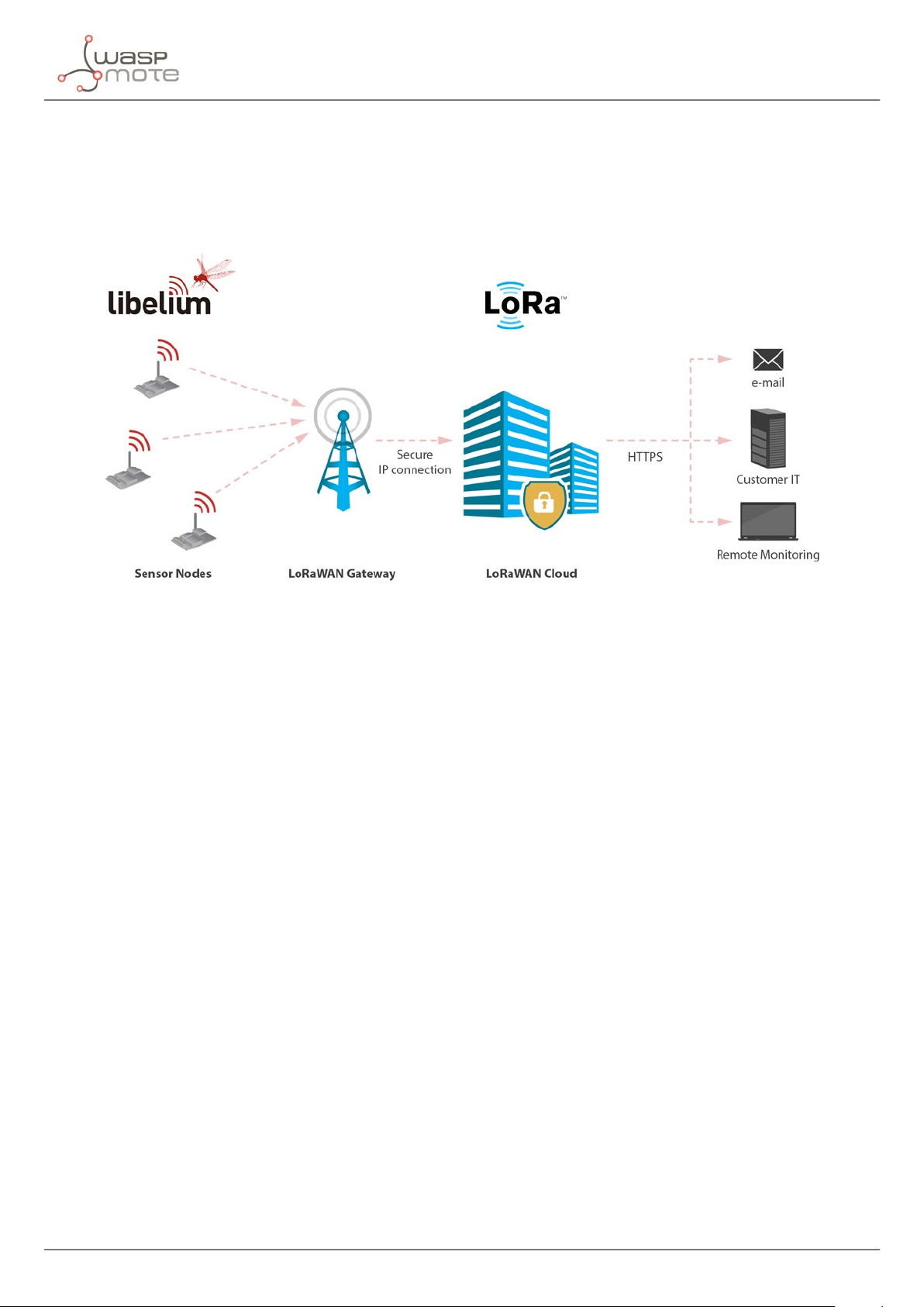
With the LoRaWAN modules we can send the data directly to any Base Station (BS) that is LoRaWAN compatible.
Some companies already oering solutions are: Kerlink, Link-Labs, Multitech, Cisco, Augtek, Manthink, Gupsy,
Gemteck, ExpEmb, Embedded Planet, Calao, RFI, etc. In order to visualize the information we will need also a
Cloud platform where the data has to be sent. Normally when you acquire a BS you can install your preferred
SW packet in order to make it work against the Cloud platform. We tested the LoRaWAN radios with three Cloud
platforms: Actility, Orbiwise and Loriot, you can nd more information about the conguration in this tutorial.
Figure: LoRaWAN network
Libelium currently oers two options of this type of radio technology: LoRa (“raw”) and LoRaWAN:
• LoRa contains only the link layer protocol and is perfect to be used in P2P communications between nodes.
You can set a topology of a maximum of 10 nodes to the same Gateway as LoRa does not make packet
management.
• LoRaWAN can handle hundreds of connections at the same time.
• LoRaWAN includes the network layer too so it is possible to send the information to any LoRaWAN Base
Station already connected to a Cloud platform. LoRaWAN modules may work in the 868/900/433 MHz bands.
• LoRa is available for the Waspmote OEM v15 platform but not for Plug & Sense! v15.
• LoRaWAN is available for both Waspmote OEM v15 and Plug & Sense! v15.
• Plug & Sense! with LoRaWAN radio is certied for Europe (CE), USA (FCC) and Canada (IC), while LoRa is not
certied.
As well as the LoRaWAN to Base Station mode, the modules may be used in two dierent more congurations.
• P2P Mode - Direct Communication between nodes (LAN Interface)
• Hybrid Mode - LoRaWAN / P2P (P2P + GW to LoRaWAN Network)
-6-
v7.6
Page 7
Introduction
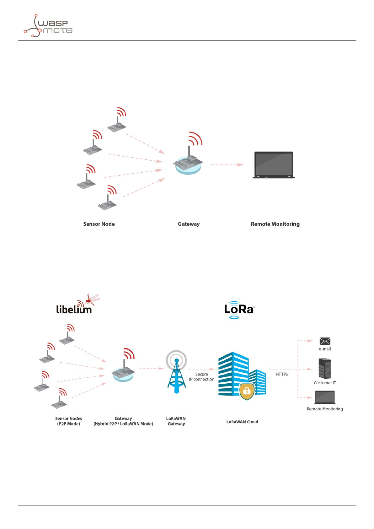
• In the P2P Mode nodes may connect directly among them and send messages directly at no cost (as they
are not using the LoRaWAN Network but just direct radio communication). This is useful as we can create
secondary networks at any time as we don’t need to change the rmware but just use specic AT Commands
in the current library. This mode works without the need of a Base Station or a Cloud account so in case
you don’t want to purchase any license (or renew the license after the initial period) you will be able to keep
on using the modules this way. For more info go to the section P2P Mode.
Figure: P2P mode
In the Hybrid Mode we use a combination of the LoRaWAN and P2P modes allowing to send just certain messages
using the LoRaWAN Network. In this case we use one node as GW of the network (P2P + LoRaWAN mode) and the
rest of the nodes in P2P mode. This mode may work using just one LoRaWAN License. For more info go to the
section Hybrid Mode.
Figure: P2P mode
-7- v7.6
Page 8

Introduction
Important:
• All documents and any examples they contain are provided as-is and are subject to change without notice.
Except to the extent prohibited by law, Libelium makes no express or implied representation or warranty of
any kind with regard to the documents, and specically disclaims the implied warranties and conditions of
merchantability and tness for a particular purpose.
• The information on Libelium’s websites has been included in good faith for general informational purposes
only. It should not be relied upon for any specic purpose and no representation or warranty is given as to its
accuracy or completeness.
-8-
v7.6
Page 9
Introduction
1.1. Technology overview
LoRaWAN is a Low Power Wide Area Network (LPWAN) specication intended for wireless battery operated
devices in regional, national or global network. LoRaWAN target key requirements of Internet of things such
as secure bi-directional communication, mobility and localization services. This standard will provide seamless
interoperability among smart Things without the need of complex local installations and gives back the freedom
to the user, developer, businesses enabling the role out of Internet of Things.
LoRaWAN network architecture is typically laid out in a star-of-stars topology in which gateways is a transparent
bridge relaying messages between end-devices and a central network server in the back-end. Gateways
are connected to the network server via standard IP connections while end-devices use single-hop wireless
communication to one or many gateways.
Communication between end-devices and gateways is spread out on dierent frequency channels and data
rates. The selection of the data rate is a trade-o between communication range and message duration. Due to
the spread spectrum technology, communications with dierent data rates do not interfere with each other and
create a set of “virtual” channels increasing the capacity of the gateway. To maximize both battery life of the enddevices and overall network capacity, the LoRaWAN network server is managing the data rate and RF output for
each end-device individually by means of an adaptive data rate (ADR) scheme.
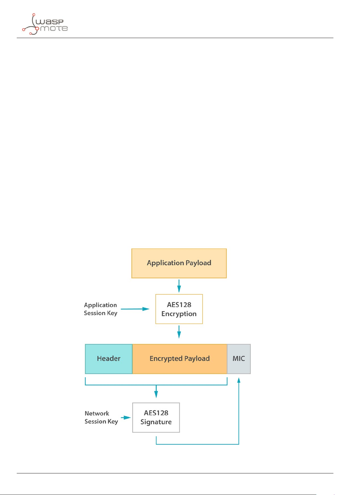
National wide networks targeting Internet of Things such as critical infrastructure, condential personal data or
critical functions for the society has a special need for secure communication. This has been solved by several
layer of encryption:
• Network Session Key (128-bit key) ensures security on network level
• Application Session Key (128-bit key) ensures end-to-end security on application level
• Application Key (128-bit key) ensures end-to-end security on application level (only OTAA procedure)
Figure: LoRaWAN security overview
-9- v7.6
Page 10
2. Hardware
2.1. Specications
The LoRaWAN module is managed via UART and it can be connected to SOCKET0 or SOCKET1.
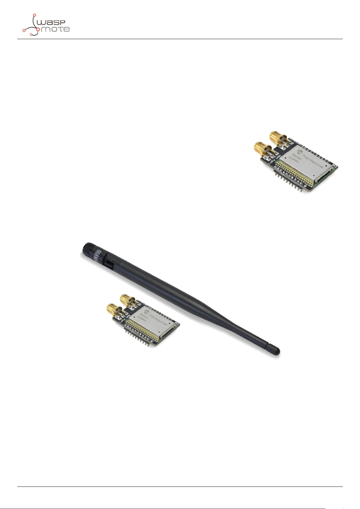
2.1.1. LoRaWAN EU
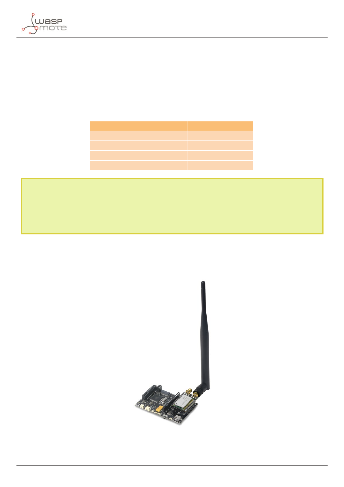
The main features of the module are listed below:
• Manufacturer: Microchip
• Model: RN2483
• Protocol: LoRaWAN 1.0, Class A
• LoRaWAN-ready
• Frequency: EU 863-870 MHz and EU 433 MHz ISM frequency bands.
• TX power: up to +14 dBm
• Sensitivity: down to -136 dBm
• Range: >15 km at suburban and >5 km at urban area. Typically, each base
station covers some km. Check the LoRaWAN Network in your area.
• Chipset consumption: 38.9 mA
• Radio bit rate: from 250 to 5470 bps
• Receiver: purchase your own base station or use networks from LoRaWAN operators
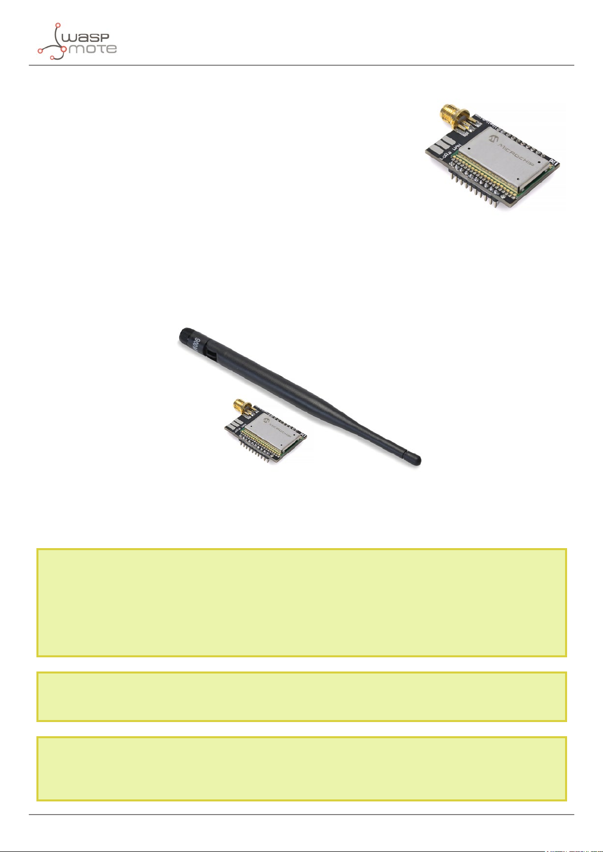
Figure: LoRaWAN EU module
Hardware
Figure: LoRaWAN EU module with antenna
-10-
v7.6
Page 11
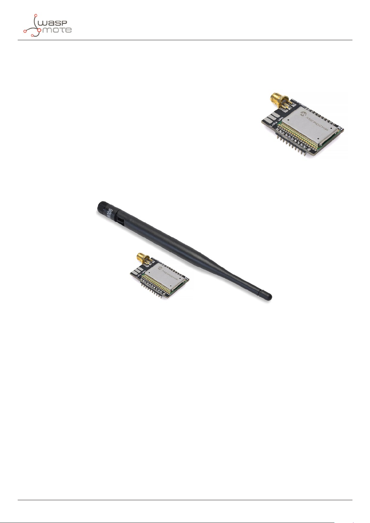
2.1.2. LoRaWAN US
The main features of the module are listed below:
• Manufacturer: Microchip
• Model: RN2903
• Protocol: LoRaWAN 1.0, Class A
• LoRaWAN-ready
• Frequency: US 902-928 MHz ISM band
• TX power: up to +18.5 dBm
• Sensitivity: down to -136 dBm
• Range: >15 km at suburban and >5 km at urban area. Typically, each base
station covers some km. Check the LoRaWAN Network in your area.
• Chipset consumption: 124.4 mA
• Radio bit rate: from 250 to 12500 bps
• Receiver: purchase your own base station or use networks from LoRaWAN operators
Hardware
Figure: LoRaWAN US module
Figure: LoRaWAN US module with antenna
-11- v7.6
Page 12

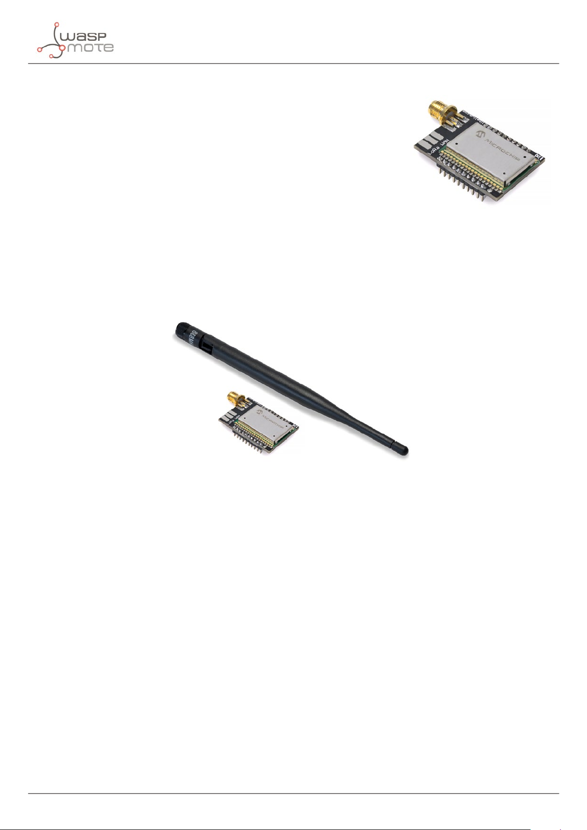
2.1.3. LoRaWAN AU
The main features of the module are listed below:
• Manufacturer: Microchip
• Model: RN2903
• Protocol: LoRaWAN 1.0.1, Class A
• LoRaWAN-ready
• Frequency: AU 915-928 MHz ISM band
• TX power: up to +18.5 dBm
• Sensitivity: down to -136 dBm
• Range: >15 km at suburban and >5 km at urban area. Typically, each base
station covers some km. Check the LoRaWAN Network in your area.
• Chipset consumption: 124.4 mA
• Radio bit rate: from 250 to 12500 bps
• Receiver: purchase your own base station or use networks from LoRaWAN operators
Hardware
Figure: LoRaWAN AU module
Figure: LoRaWAN AU module with antenna
-12-
v7.6
Page 13
2.1.4. LoRaWAN IN
The main features of the module are listed below:
• Manufacturer: Microchip
• Model: RN2903
• Protocol: LoRaWAN 1.0.1, Class A
• LoRaWAN-ready
• Frequency: IN 865-867 MHz ISM band
• TX power: up to +18.5 dBm
• Sensitivity: down to -136 dBm
• Range: >15 km at suburban and >5 km at urban area. Typically, each base
station covers some km. Check the LoRaWAN Network in your area.
• Chipset consumption: 124.4 mA
• Radio bit rate: from 250 to 12500 bps
• Receiver: purchase your own base station or use networks from LoRaWAN operators
Hardware
Figure: LoRaWAN IN module
Figure: LoRaWAN IN module with antenna
-13- v7.6
Page 14
2.1.5. LoRaWAN ASIA-PAC / LATAM
The main features of the module are listed below:
• Manufacturer: Microchip
• Model: RN2903
• Protocol: LoRaWAN 1.0.1, Class A
• LoRaWAN-ready
• Frequency: AS 923 MHz ISM band
• TX power: up to +18.5 dBm
• Sensitivity: down to -136 dBm
• Range: >15 km at suburban and >5 km at urban area. Typically, each base
station covers some km. Check the LoRaWAN Network in your area.
• Chipset consumption: 124.4 mA
• Radio bit rate: from 250 to 12500 bps
• Receiver: purchase your own base station or use networks from LoRaWAN operators
Hardware
Figure: LoRaWAN AU module
Figure: LoRaWAN ASIA-PAC / LATAM module with antenna
Note: The user must check the allowed bands, channels and transmission power, in order to respect the regulations
in the operation country.
Libelium commercializes dierent items depending on the band the user wants to use. In the case of 868 and 433,
the module is the same, but the antenna is dierent for each band. The module for EU (868) and 433 MHz includes 2
RP-SMA connectors for the antenna. One is for the 868 band and the other for the 433 band. A sticker on the bottom
of the modules species clearly where to screw the antenna.
Note: Any LoRaWAN module is provided with a special antenna (for 433 or for 868 or for 900 MHz), which enables
maximum range.
Note: Due to the propagation characteristics of the sub-GHz bands, the near eld eect could make that 2 modules
cannot communicate if they are placed very close (< 1 m). We suggest to keep a minimum distance of 3 or 4 meters
between modules.
-14-
v7.6
Page 15
2.1.6. LoRaWAN JP / KR
The main features of the module are listed below:
• Manufacturer: Murata
• Model: CMWX1ZZABZ
• Protocol: LoRaWAN 1.0.1, Class A
• LoRaWAN-ready
• Frequency: AS 923 MHz ISM band and KR 920-923 MHz ISM band
• TX power: up to +16 dBm
• Sensitivity: down to -135.5 dBm
• Range: >15 km at suburban and >5 km at urban area.
Typically, each base station covers some km.
Check the LoRaWAN Network in your area.
• Chipset consumption: 96.7 mA
• Radio bit rate: from 250 to 5470 bps
• Receiver: purchase your own base station or use networks from LoRaWAN operators
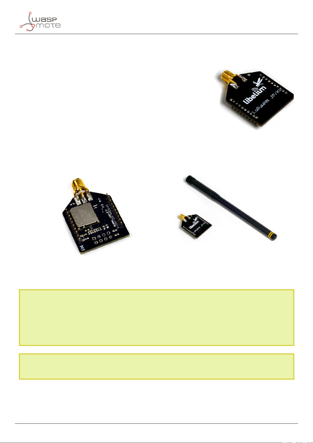
Figure: LoRaWAN JP / KR module
Hardware
Figure: Bottom of the LoRaWAN JP / KR and module with antenna
Note: The user must check the allowed bands, channels and transmission power, in order to respect the regulations
in the operation country.
Libelium commercializes dierent items depending on the band the user wants to use. In the case of 868 and 433,
the module is the same, but the antenna is dierent for each band. The module for EU (868) and 433 MHz includes 2
RP-SMA connectors for the antenna. One is for the 868 band and the other for the 433 band. A sticker on the bottom
of the modules species clearly where to screw the antenna.
Note: Any LoRaWAN module is provided with a special antenna (for 433 or for 868 or for 900 MHz or for 916 MHz
[JP / KR]), which enables maximum range
-15- v7.6
Page 16
Hardware
Note: Due to the propagation characteristics of the sub-GHz bands, the near eld eect could make that 2 modules
cannot communicate if they are placed very close (< 1 m). We suggest to keep a minimum distance of 3 or 4 meters
between modules.
2.2. Region standards
The LoRaWAN Specication settled by the LoRa Alliance establishes the parameters that must be complied for
every region. Check the compatibility table below, showing the areas supported by our LoRaWAN versions for the
moment.
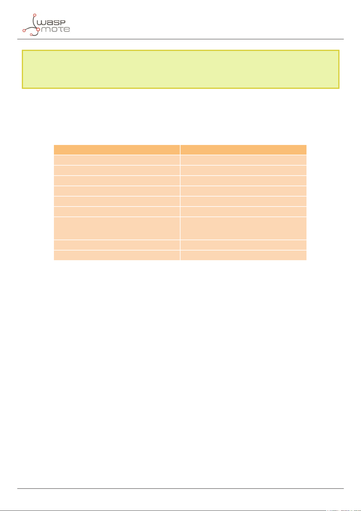
Region Supported by
EU 863-870 MHz ISM Band (Europe) LoRaWAN EU
US 902-928 MHz ISM Band (United States) LoRaWAN US
CN 779-787 MHz ISM Band (China) Not supported
AU 915-928 MHz ISM Band (Australia) LoRaWAN AU
CN 470-510 MHz ISM Band (China) Not supported
AS 923 MHz ISM Band (ASEAN) LoRaWAN ASIA-PAC / LATAM
AS 923 MHz ISM Band (ASEAN)
KR 920-923 MHz ISM Band (South Korea) LoRaWAN JP / KR
INDIA 865-867 ISM Band (India) LoRaWAN IN
Figure: Regional compatibility table
LoRaWAN ASIA-PAC / LATAM
LoRaWAN JP / KR (special for Japan)
-16-
v7.6
Page 17
Hardware
2.3. Power consumption
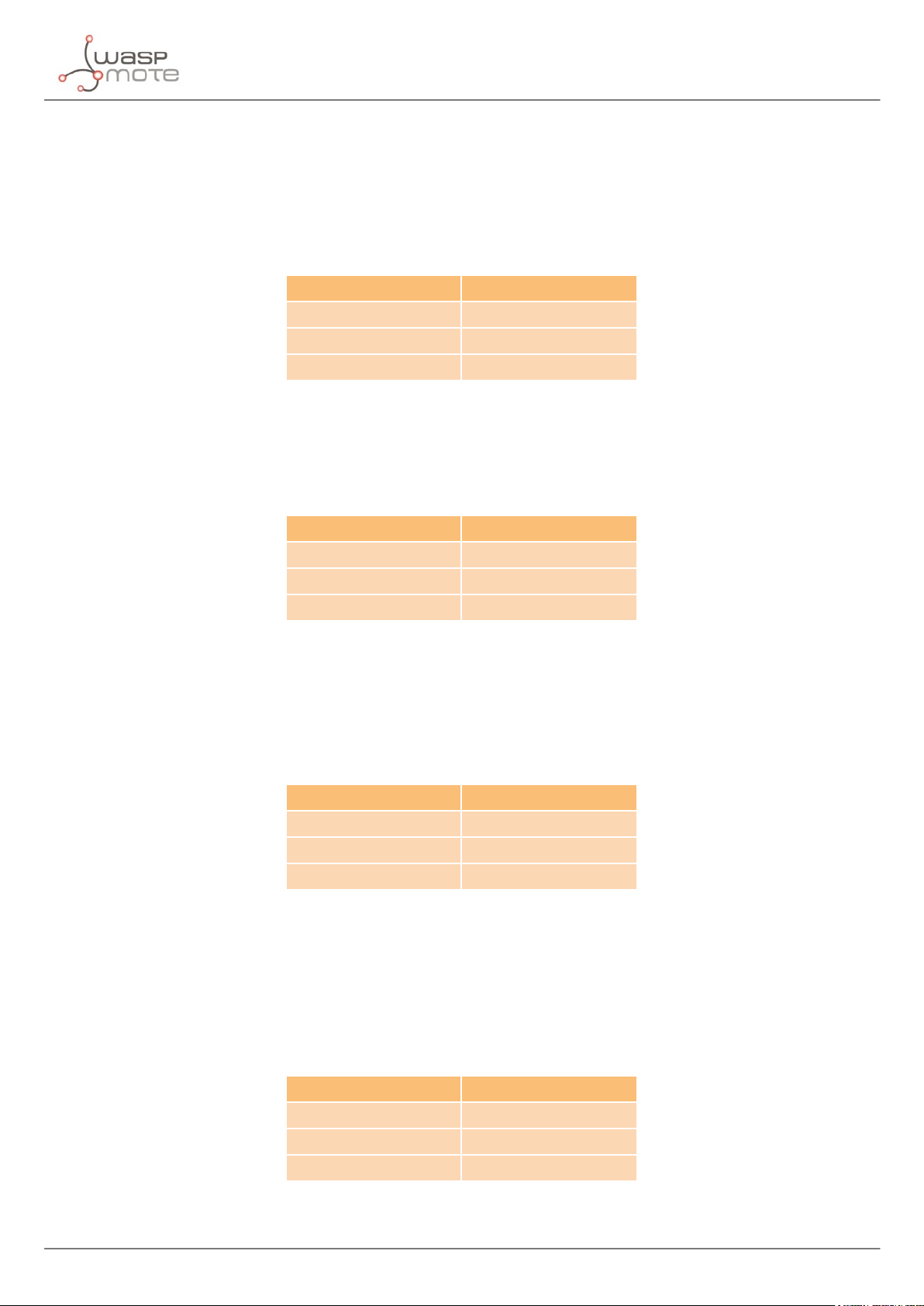
2.3.1. LoRaWAN EU
The LoRaWAN EU module is powered at 3.3 V. The next table shows the module’s average current consumption
in dierent states of the module.
State Power Consumption
On 2.8 mA
Transmitting data 38.9 mA
Receiving data 14.2 mA
Figure: Power consumption table
2.3.2. LoRaWAN US
The LoRaWAN US module is powered at 3.3 V. The next table shows the module’s average current consumption
in dierent states of the module.
State Power Consumption
On 2.7 mA
Transmitting data 124.4 mA
Receiving data 13.5 mA
Figure: Power consumption table
2.3.3. LoRaWAN AU
The LoRaWAN AU module is powered at 3.3 V. The next table shows the module’s average current consumption
in dierent states of the module.
State Power Consumption
On 2.7 mA
Transmitting data 124.4 mA
Receiving data 13.5 mA
Figure: Power consumption table
2.3.4. LoRaWAN IN
The LoRaWAN IN module is powered at 3.3 V. The next table shows the module’s average current consumption
in dierent states of the module.
State Power Consumption
On 2.7 mA
Transmitting data 124.4 mA
Receiving data 13.5 mA
Figure: Power consumption table
-17- v7.6
Page 18
Hardware
2.3.5. LoRaWAN ASIA-PAC / LATAM
The LoRaWAN ASIA-PAC / LATAM module is powered at 3.3 V. The next table shows the module’s average current
consumption in dierent states of the module.
State Power Consumption
On 2.7 mA
Transmitting data 124.4 mA
Receiving data 13.5 mA
Figure: Power consumption table
2.3.6. LoRaWAN JP / KR
The LoRaWAN JP / KR module is powered at 3.3 V. The next table shows the module’s average current consumption
in dierent states of the module.
Figure: Power consumption table
State Power Consumption
On 1.1 mA
Transmitting data 96.1 mA
Receiving data 27 mA
-18-
v7.6
Page 19
Hardware
2.4. Time consumption
The elapsed periods dened in this chapter take into account the following steps depending on the case:
• Join to a network and send unconrmed data
• Join to a network and send conrmed data
These periods of time depend on the data rate set which is dened by the spreading factor and signal bandwidth
congured.
Transmit mode Time elapsed
Send unconrmed at 5470 bps ~ 2.8 seconds
Send unconrmed at 250 bps ~ 4.2 seconds
Send conrmed at 5470 bps ~ 1.7 seconds
Send conrmed at 250 bps ~ 4.2 seconds
Note: When transmitting in ISM frequency bands, the user must ensure that the communication is not exceeding the
permitted time using the chosen frequency channel (for example, 1% of time). This depends on the local regulations
(CE, FCC, etc). It is the responsibility of the user to know the allowed time of use in the occupied frequency band and
respect it. Ignoring this, could lead to considerable penalties. Also, a LoRaWAN back-end operator could cut o the
service or apply extra fees, it they detect that the user is exceeding the maximum number of frames or data in a
period of time.
2.5. How to connect the module
This module can be connected to both SOCKET0 and SOCKET1 on the Waspmote board.
Figure: Module connected to Waspmote in SOCKET0
In order to connect the module to the SOCKET1, the user must use the Expansion Radio Board.
-19- v7.6
Page 20
Hardware
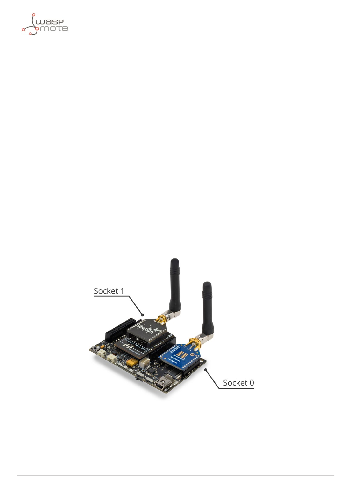
2.6. Expansion Radio Board
The Expansion Board allows to connect two communication modules at the same time in the Waspmote sensor
platform. This means a lot of dierent combinations are possible using any of the wireless radios available for
Waspmote: 802.15.4, ZigBee, DigiMesh, 868 MHz, 900 MHz, LoRa, WiFi, GPRS, GPRS+GPS, 3G, 4G, Sigfox, LoRaWAN,
Bluetooth Pro, Bluetooth Low Energy and RFID/NFC. Besides, the following Industrial Protocols modules are
available: RS-485/Modbus, RS-232 Serial/Modbus and CAN Bus.
Some of the possible combinations are:
• LoRaWAN - GPRS
• 802.15.4 - Sigfox
• 868 MHz - RS-485
• RS-232 - WiFi
• DigiMesh - 4G
• RS-232 - RFID/NFC
• WiFi - 3G
• CAN Bus - Bluetooth
• etc.
Remark: GPRS, GPRS+GPS, 3G and 4G modules do not need the Expansion Board to be connected to Waspmote. They
can be plugged directly in the socket1.
In the next photo you can see the sockets available along with the UART assigned. On one hand, SOCKET0 allows
to plug any kind of radio module through the UART0. On the other hand, SOCKET1 permits to connect a radio
module through the UART1.
Figure: Use of the Expansion Board
The API provides a function called ON() in order to switch the module on. This function supports a parameter
which permits to select the SOCKET. It is possible to choose between SOCKET0 and SOCKET1.
Selecting SOCKET0: LoRaWAN.ON(SOCKET0);
Selecting SOCKET1: LoRaWAN.ON(SOCKET1);
-20-
v7.6
Page 21

Hardware
The rest of functions are used the same way as they are used with older API versions. In order to understand
them, we recommend to read this guide.
Warnings:
• Avoid to use DIGITAL7 pin when working with the Expansion Board. This pin is used for setting the XBee into
sleep mode.
• Avoid to use DIGITAL6 pin when working with the Expansion Board. This pin is used as power supply for the
Expansion Board.
• Incompatibility with Sensor Boards:
- Agriculture v30 and Agriculture PRO v30: Incompatible with Watermark and solar radiation sensors
- Events v30: Incompatible with interruption shift register
- Gases v30: DIGITAL6 is incompatible with CO2 (SOCKET_2) and DIGITAL7 is incompatible with NO2
(SOCKET_3)
- Smart Water v30: DIGITAL7 incompatible with conductivity sensor
- Smart Water Ions v30: Incompatible with ADC conversion (sensors cannot be read if the Expansion Board
is in use)
- Gases PRO v30: Incompatible with SOCKET_2 and SOCKET_3
- Cities PRO v30: Incompatible with SOCKET_3. I2C bus can be used. No gas sensor can be used.
-21- v7.6
Page 22
Software
3. Software
The Waspmote device communicates with the LoRaWAN module via UART. So dierent commands are sent from
the microcontroller unit to the module so as to perform dierent tasks.
3.1. Waspmote libraries
3.1.1. Waspmote LoRaWAN les
The les related to the LoRaWAN libraries for these modules are:
WaspLoRaWAN.h
WaspLoRaWAN.cpp
It is mandatory to include the LoRaWAN library when using these modules. So the following line must be added
at the beginning of the code:
#include <WaspLoRaWAN.h>
3.1.2. Class constructor
To start using the Waspmote LoRaWAN library, an object from the WaspLoRaWAN class must be created. This object,
called LoRaWAN, is already created by default inside Waspmote LoRaWAN library. It will be used through this guide
to show how Waspmote works.
When using the class constructor, all variables are initialized to a default value.
3.1.3. API constants
The API constants used in functions are:
Constant Description
LORAWAN_ANSWER_OK
LORAWAN_ANSWER_ERROR
LORAWAN_NO_ANSWER
LORAWAN_INIT_ERROR
LORAWAN_LENGTH_ERROR
LORAWAN_SENDING_ERROR
LORAWAN_NOT_JOINED
LORAWAN_INPUT_ERROR
LORAWAN_VERSION_ERROR
RN2483_MODULE
RN2903_MODULE
RN2903_IN_MODULE
RN2903_AS_MODULE
ABZ_MODULE
BAND_JP923
BAND_KR920
Successful response to a function
Erratic response to a function
No response to a function
Required keys to join to a network were not initialized
Data to be sent length limit exceeded
Server did not response
Module has not joined a network
Invalid input parameter
The module does not support this function
LoRaWAN module plugged is LoRaWAN EU
LoRaWAN module plugged is LoRaWAN US
LoRaWAN module plugged is LoRaWAN IN
LoRaWAN module plugged is LoRaWAN ASIA-PAC / LATAM
LoRaWAN module plugged is LoRaWAN JP / KR
LoRaWAN module is using the AS923 band
LoRaWAN module is using the KR920-923 band
-22-
v7.6
Page 23
3.1.4. API variables
The variables used inside functions and Waspmote codes are:
Constant Description
_buffer
_length
_def_delay
_baudrate
_uart
_adr
_ar
_eui
_devEUI
_appEUI
_nwkSKey
_appSKey
_appKey
_devAddr
_band
_margin
_gwNumber
_freq
_radioFreq
_radioFreqDev
_preambleLength
_dCycle
_drrMin
_drrMax
_dCyclePS
_crcStatus
_powerIndex
_dataRate
_retries
_upCounter
The buer of memory used for storing the responses from the
module
The useful length of the buer
The time to wait after sending every command until listen for a
response
The baudrate to be used when the module is switched on
The selected UART (regarding the socket used: SOCKET0 or
SOCKET1)
The adaptive data rate state (on or o)
The automatic reply state (on or o)
The buer used for storing the preprogrammed globally unique
identier from the module's hardware
The buer used for storing the globally unique identier for the
module (software programmable)
The buer used for storing the application identier for the
module
The buer used for storing the network session key for the module
The buer used for storing the application session key for the
module
The buer used for storing the application key for the module
The buer used for storing network device address for module
The buer used for storing the frequency band
The demodulation margin received in the last Link Check Answer
frame
The number of gateways successfully received the last Link Check
Answer frame
The buer used for storing the operating frequency for every
channel
The transceiver operating frequency
The transceiver frequency deviation
The preamble length for transceiver
The buer used for storing the operating duty cycle for every
channel
The minimum operating data rate range for every channel
The maximum operating data rate range for every channel
The duty cycle prescaler (which can only be congured by the
server)
The CRC status to determine if it is to be included during operation
The output power to be used on LoRaWAN transmissions
The data rate to be used on LoRaWAN transmissions
The number of retransmissions for an uplink
The value of the uplink frame counter
Software
-23- v7.6
Page 24
Software
_downCounter
_radioPower
_radioSF
_radioRxBW
_radioCR
_radioWDT
_radioBW
_radioSNR
_radioMode
_radioBitRate
_supplyPower
_rx2DataRate
_rx2Frequency
_rx1Delay
_macStatus
_status
_data
_port
_dataReceived
_version
_bandABZ
The value of the downlink frame counter
The output power level used by the transceiver
The spreading factor to be used by the transceiver
The receiving bandwidth used by the transceiver
The coding rate used by the transceiver
The time to be used by the transceiver watchdog timer
The value used for the transceiver bandwidth
The SNR value for the last received packet by the transceiver
The buer to save the operative radio mode
The operative radio bit rate
The voltage level read by the module
The second receiving window data rate
The second receiving window frequency
The rst receiving window delay
The MAC status register from the module
The status of every LoRaWAN channel
The buer of memory used for storing data received from the
back-end
The port where data was received
The ag used to inform if any data was received
The version of the module plugged into Waspmote
Band used for the LoRaWAN JP / KR type module
3.1.5. API functions
Through this guide there are lots of examples of using functions. In these examples, API functions are called to
execute the commands, storing in their related variables the parameter value in each case. The functions are
called using the predened object LoRaWAN.
All public functions return one of these possible values:
• LORAWAN_ANSWER_OK = 0
• LORAWAN_ANSWER_ERROR = 1
• LORAWAN_NO_ANSWER = 2
• LORAWAN_INIT_ERROR = 3
• LORAWAN_LENGTH_ERROR = 4
• LORAWAN_SENDING_ERROR = 5
• LORAWAN_NOT_JOINED = 6
• LORAWAN_INPUT_ERROR = 7
• LORAWAN_VERSION_ERROR = 8
-24-
v7.6
Page 25

Software
3.2. Module system management features
3.2.1. Switch on
The ON() function allows to switch on the LoRaWAN module, it opens the MCU UART for communicating with the
module and it automatically enters into command mode.
In addition, when the module has been powered and communication is opened, this function checks whether
a module is plugged to the socket and which type of module has been plugged. This check is done within every
function that reboots the module such as “ON”, “reset” or “factoryReset”.
After this step the module will be able to receive commands to congure it or send packets. It is necessary to
indicate the socket that it is being used: SOCKET0 or SOCKET1.
Example of use for SOCKET0:
{
LoRaWAN.ON(SOCKET0);
}
Related variable:
LoRaWAN._version → Stores the module’s version
Figure: LoRaWAN module in SOCKET0
-25- v7.6
Page 26

Software
3.2.2. Switch o
The OFF() function allows the user to switch o the LoRaWAN module and close the UART. This function must be
called in order to keep battery level when the module is not going to be managed. It is necessary to indicate the
socket that it is being used: SOCKET0 or SOCKET1.
Example of use for SOCKET0:
{
LoRaWAN.OFF(SOCKET0);
}
3.2.3. Module software reset
The reset() function allows the user to reset and restart the LoRaWAN module. The stored internal congurations
will be loaded automatically upon reboot.
Example of use:
{
LoRaWAN.reset();
}
Related variable:
LoRaWAN._version → Stores the module’s version
3.2.4. Module factory reset
The factoryReset() function allows the user to reset the module’s conguration data and user EEPROM to factory
default values and restart the module.
Example of use:
{
LoRaWAN.factoryReset();
}
Related variable:
LoRaWAN._version → Stores the module’s version
Examples of LoRaWAN conguration:
www.libelium.com/development/waspmote/examples/lorawan-01a-congure-module-eu
www.libelium.com/development/waspmote/examples/lorawan-01b-congure-module-us
3.2.5. Preprogrammed unique identier (EUI)
The getEUI() function allows the user to query the preprogrammed EUI node address from the module. The
preprogrammed EUI node address is a read-only value and cannot be changed or erased. It is a global unique
64-bit identier.
Example of use:
{
LoRaWAN.getEUI();
}
Related variable:
LoRaWAN._eui → Stores the module’s EUI
-26-
v7.6
Page 27

Software
3.3. LoRaWAN parameters
3.3.1. Device EUI
The setDeviceEUI() function allows the user to set the 64-bit hexadecimal number representing the device EUI.
There are two function prototypes which are explained below:
• No input device EUI is specied, then the preprogrammed EUI is used as the device EUI.
• A user-provided device EUI is specied as input.
The getDeviceEUI() function allows the user to query the device EUI which was previously set by the user. The
attribute _devEUI permits to access to the settings of the module. The default value is 0000000000000000.
Depending on the network to join, it is needed to congure a random device EUI or a xed device EUI provided
by the back-end. This matter relies on the registering process for new devices in each back-end. For further
information please go to “LoRaWAN back-ends” chapter.
Example for preprogrammed EUI:
{
LoRaWAN.setDeviceEUI();
LoRaWAN.getDeviceEUI();
}
Example for user-provided device EUI:
{
LoRaWAN.setDeviceEUI(“0102030405060708”);
LoRaWAN.getDeviceEUI();
}
Related variable:
LoRaWAN._devEUI → Stores the previously set device EUI
Examples of LoRaWAN conguration:
www.libelium.com/development/waspmote/examples/lorawan-01a-congure-module-eu
www.libelium.com/development/waspmote/examples/lorawan-01b-congure-module-us
3.3.2. Device address
The setDeviceAddr() function allows the user to set the 32-bit hexadecimal number representing the device
address. This address must be unique to the current network. There are two function prototypes which are
explained below:
• No input device address is specied, then the last 4 bytes of the preprogrammed EUI are set as device address.
• A user-provided device address is specied as input.
The getDeviceAddr() function allows the user to query the device address which was previously set by the
user. The attribute _devAddr permits to access to the settings of the module. The range goes from 00000000 to
FFFFFFFF. The default value is 00000000.
-27- v7.6
Page 28

Software
Depending on the network to join, it is possible congure a random device address or a xed device address. This
matter depends on the back-end and the registering process for new devices. For further information please go
to “LoRaWAN back-ends” chapter.
Example for using the preprogrammed EUI:
{
LoRaWAN.setDeviceAddr();
LoRaWAN.getDeviceAddr();
}
Example for user-provided device address:
{
LoRaWAN.setDeviceAddr(“01020304”);
LoRaWAN.getDeviceAddr();
}
Related variable:
LoRaWAN._devAddr → Stores the previously set device address
Examples of LoRaWAN conguration:
www.libelium.com/development/waspmote/examples/lorawan-01a-congure-module-eu
www.libelium.com/development/waspmote/examples/lorawan-01b-congure-module-us
3.3.3. Application Session Key
The setAppSessionKey() function allows the user to set the 128-bit hexadecimal number representing the
application session key.
All payloads are encrypted using an AES algorithm with a 128-bit secret key, the Application Session Key. Each
end-device has its own unique Application Session Key only known by the end-device and the application server.
Figure: Use of application session key
-28-
v7.6
Page 29

Software
The attribute _appSKey stores the application session key previously set by the user. The range goes from 000000
00000000000000000000000000 to FFFFFFFFFFFFFFFFFFFFFFFFFFFFFFFF.
Example of use:
{
LoRaWAN.setAppSessionKey(“00102030405060708090A0B0C0D0E0F”);
}
Related variable:
LoRaWAN._appSKey → Stores the previously set application session key
Examples of LoRaWAN conguration:
www.libelium.com/development/waspmote/examples/lorawan-01a-congure-module-eu
www.libelium.com/development/waspmote/examples/lorawan-01b-congure-module-us
3.3.4. Network session key
The setNwkSessionKey() function allows the user to set the 128-bit hexadecimal number representing the
network session key.
All frames contain a 32-bit cryptographic Message Integrity Check (MIC) signature computed using the AES
algorithm with a 128-bit secret key, the Network Session Key. Each end-device has its own Network Session Key
only known by the end-device and the network server.
Figure: Use of network session key
-29- v7.6
Page 30

Software
The attribute _nwkSKey stores the network session key previously set by the user. The range goes from 00000000
000000000000000000000000 to FFFFFFFFFFFFFFFFFFFFFFFFFFFFFFFF.
Example of use:
{
LoRaWAN.setNwkSessionKey(“00102030405060708090A0B0C0D0E0F”);
}
Related variable:
LoRaWAN._nwkSKey → Stores the previously set network session key
Examples of LoRaWAN conguration:
www.libelium.com/development/waspmote/examples/lorawan-01a-congure-module-eu
www.libelium.com/development/waspmote/examples/lorawan-01b-congure-module-us
3.3.5. Application EUI
The setAppEUI() function allows the user to set the 64-bit hexadecimal number representing the application
identier. This parameters is a global application identier that uniquely identies the application provider (i.e.,
owner) of the module.
Example of use:
{
LoRaWAN.setAppEUI(“1112131415161718”);
}
Related variable:
LoRaWAN._appEUI → Stores the previously set application EUI
3.3.6. Application key
The setAppKey() function allows the user to set the 128-bit hexadecimal number representing the application
key. Whenever an end-device joins a network via OTAA, the Application Key is used to derive the session keys,
Network Session Key and Application Session Key, which are specic for that end-device to encrypt and verify
network communication and application data.
The attribute _appKey stores the application session key previously set by the user. The range goes from 000000
00000000000000000000000000 to FFFFFFFFFFFFFFFFFFFFFFFFFFFFFFFF.
Example of use:
{
LoRaWAN.setAppKey(“00102030405060708090A0B0C0D0E0F”);
}
Related variable:
LoRaWAN._appKey → Stores the previously set application key
Examples of LoRaWAN conguration:
www.libelium.com/development/waspmote/examples/lorawan-01a-congure-module-eu
www.libelium.com/development/waspmote/examples/lorawan-01b-congure-module-us
-30-
v7.6
Page 31

Software
3.4. LoRaWAN module activation
To participate in a LoRaWAN network, each module has to be personalized and activated.
Activation of a module can be achieved in two ways, either via Over-The-Air Activation (OTAA) when an end-device
is deployed or reset, or via Activation By Personalization (ABP) in which the two steps of end-device personalization
and activation are done as one step.
3.4.1. Over-The-Air Activation (OTAA)
For OTAA, modules must follow a join procedure prior to participating in data exchanges with the network server.
A module has to go through a new join procedure every time it has lost the session context information.
The OTAA join procedure requires the module to be personalized with the following information before its starts
the join procedure:
• Device EUI (64-bit)
• Application EUI (64-bit)
• Application Key (128-bit)
After joining through OTAA, the module and the network exchanged the Network Session Key and the Application
Session Key which are needed to perform communications.
3.4.2. Activation By Personalization (ABP)
Activating a module by ABP means that the device address and the two session keys are directly stored into the
module instead of the Device EUI, Application EUI and the Application Key. The module is equipped with the
required information for participating in a specic LoRa network when started.
Each module should have a unique set of Network Session Key and Application Session Key. Compromising the
keys of one module shouldn‘t compromise the security of the communications of other devices. The process to
build those keys should be such that the keys cannot be derived in any way from publicly available information.
The ABP join procedure requires the module to be personalized with the following information before its starts
the join procedure:
• Device address (32-bit)
• Network Session Key (128-bit key) ensures security on network level
• Application Session Key (128-bit key) ensures end-to-end security on application level
3.4.3. Join a network
Before sending packets to a gateway, the node must join a network rst. The joinABP() function allows the user to
attempt joining the network using the Activation By Personalization mode (ABP). The joinOTAA() function allows
the user to attempt joining the network using the Over the Air Activation mode (OTAA). Before joining the network,
the specic parameters for activation should be congured depending on the joining procedure.
• Join ABP
Before joining the network, the specic parameters for activation should be congured: device EUI, device address,
network session key and application session key.
Example of use:
{
LoRaWAN.joinABP();
}
-31- v7.6
Page 32

Software
• Join OTAA
Before joining the network, the specic parameters for activation should be congured: device EUI, application
EUI and application key.
Example of use:
{
LoRaWAN.joinOTAA();
}
After joining via OTAA successfully, the module will be able to join the network in ABP mode in future joining
procedures. The session keys are stored in module’s memory, so it is possible to power down the module and
restart it using ABP for joining the network with the previously stored keys.
-32-
v7.6
Page 33

Software
3.5. LoRaWAN mode features
3.5.1. Operational ISM bands
The resetMacCong() function allows the user to reset the software LoRaWAN stack and initialize it with the
parameters for the selected band: 433 MHz, 868 MHz or 900 MHz.
The getBand() function allows the user to query the current frequency band of operation. This function is not
available for the LoRaWAN US and AU modules since they can only work in the 902-928 MHz ISM band for the US
version and 915-928 MHz ISM band for the AU version. The attribute saveCong() function due to keep the band
conguration after a reboot. Value can be either 433 or 868.
Example of use:
{
LoRaWAN.resetMacCong(433);
LoRaWAN.getBand();
}
Related variable:
LoRaWAN._band → Stores the current frequency band of operation
3.5.2. Send data to a LoRaWAN gateway
• Sending unconrmed packets
Figure: Sending unconrmed packets without ACK
-33- v7.6
Page 34

Software
The sendUnconrmed() function allows the user to transmit data on a specied port number. This function will
not expect any acknowledgement back from the server. It is necessary to indicate the port to use. The range is
from 1 to 223. The second input of the sending function is the payload of the packet to send. The payload must be
specied in hexadecimal format as a string.
Example of use:
{
uint8_t port = 1;
char data[] = “010203040506070809”;
LoRaWAN.sendUnconrmed( port, data);
}
Example of sending a packet without ACK:
www.libelium.com/development/waspmote/examples/lorawan-06-join-abp-send-unconrmed
www.libelium.com/development/waspmote/examples/lorawan-09-join-otaa-send-unconrmed
There is a second sendUnconrmed() function prototype which permits to send a packet dened as an array of
bytes. So the function expects three inputs: port, pointer to the data and length of the data.
Example of use:
{
uint8_t port = 1;
uint8_t data[] = {0x01, 0x02, 0x03, 0x04, 0x05, 0x06};
LoRaWAN.sendUnconrmed( port, data, 6);
}
Examples of sending a packet using the alternative prototype:
www.libelium.com/development/waspmote/examples/lorawan-08-join-abp-send-frame
www.libelium.com/development/waspmote/examples/lorawan-11-join-otaa-send-frame
The length of the payload capable of being transmitted is dependent upon the set data rate. Please refer to the
“Data rate” section for the payload length values.
• Sending conrmed packets (with ACK)
Figure: Sending conrmed packets with ACK
-34-
v7.6
Page 35

Software
The sendConrmed() function allows the user to transmit data on a specied port number. This function will expect
an acknowledgement from the server. If no ACK is received, the message will be retransmitted automatically up to
a maximum of times specied by the setRetries() function. It is necessary to indicate the port to use. The range
is from 1 to 223. The second input of the sending function is the payload of the packet to send. The payload must
be specied in hexadecimal format as a string.
Example of use:
{
uint8_t port = 1;
char data[] = “010203040506070809”;
LoRaWAN.sendConrmed( port, data);
}
Example of sending a packet with ACK:
www.libelium.com/development/waspmote/examples/lorawan-07-join-abp-send-conrmed
www.libelium.com/development/waspmote/examples/lorawan-10-join-otaa-send-conrmed
There is a second sendConrmed() function prototype which permits to send a packet dened as an array of bytes.
So the function expects three inputs: port, pointer to the data and length of the data.
Example of use:
{
uint8_t port = 1;
uint8_t data[] = {0x01, 0x02, 0x03, 0x04, 0x05, 0x06};
LoRaWAN.sendConrmed( port, data, 6);
}
Examples of sending a packet using the alternative prototype:
www.libelium.com/development/waspmote/examples/lorawan-08-join-abp-send-frame
www.libelium.com/development/waspmote/examples/lorawan-11-join-otaa-send-frame
The length of the payload capable of being transmitted is dependent upon the set data rate. Please refer to the
“Data rate” section for the payload length values.
3.5.3. Receiving data from a LoRaWAN gateway
Note that not every back-end is able to send data to end devices. The back-ends which are able to perform data
downlink use the ACK process to send a special ACK frame containing data. So once the user programs a downlink
process, this downlink data will be received by the target module the next time it performs a transmission.
There is no specic function to receive data from back-ends in this library. The sendUnconrmed() and the
sendConrmed() functions check if any special ACK is received and store data if any has been received. In case
data has been received, _dataReceived ag will be set to true.
Related variables:
LoRaWAN._port → Stores the port used by the back-ends to send data
LoRaWAN._data → Stores the received data
LoRaWAN._dataReceived → Data received ag
-35- v7.6
Page 36

Software
3.5.4. Save conguration
The saveCong() function allows the user to save LoRaWAN Class A protocol conguration parameters to the
module’s non-volatile memory. This function must be issued after the conguration parameters have been
appropriately set.
The LoRaWAN Class A protocol conguration savable parameters are:
• Band
• Uplink Frame Counter
• Downlink Frame Counter
• Data Rate
• Adaptive Data Rate state
• Device EUI
• Application EUI
• Application Key
• Network Session Key
• Application Session Key
• Device Address
• Second receiving window parameters
• All Channel Parameter
- Frequency
- Duty Cycle
- Data Rate Range
- Status
There are some exceptions for the LoRaWAN US module, it does not save:
• Band, since it does not use this parameter
• Data rate
• Channel frequency, preset according to specication
• Duty cycle, since it does not use this parameter
Example of use:
{
LoRaWAN.saveCong();
}
Examples of LoRaWAN conguration:
www.libelium.com/development/waspmote/examples/lorawan-01a-congure-module-eu
www.libelium.com/development/waspmote/examples/lorawan-01b-congure-module-us
The macResume() function allows the user to enable LoRaWAN mode. After switching on the module it is not
mandatory to call this function because the default mode upon reboot is LoRaWAN mode. However, if P2P mode
was previously set and the user needs to switch back to LoRaWAN mode, then this function must be called. This
function is not available for the LoRaWAN JP / KR module.
Example of use:
{
LoRaWAN.macResume();
}
-36-
v7.6
Page 37

Software
3.5.5. Power level
The setPower() function allows the user to set the output power to be used on the next transmissions.
The getPower() function allows the user to query the device power index which was previously set by the user.
The attribute _powerIndex permits to access to the settings of the module. The range goes from 0 to 5 for the 433
MHz frequency band and from 1 to 5 for the 868 MHz frequency band. LoRaWAN US and LoRaWAN AU power
index values can be: 5, 7, 8, 9 or 10. LoRaWAN IN power index values go from 0 to 5. LoRaWAN ASIA-PAC / LATAM
power index values go from 0 to 5. LoRaWAN JP / KR power index values go from 0 to 7.
Power Index Power level (868 MHz) Power level (433 MHz)
0 N / A 10 dBm
1 14 dBm 7 dBm
2 11 dBm 4 dBm
3 8 dBm 1 dBm
4 5 dBm -2 dBm
5 2 dBm -5 dBm
Figure: Power levels table (LoRaWAN EU /433 module)
Power Index Power level (900 MHz)
5 20 dBm
7 16 dBm
8 14 dBm
9 12 dBm
10 10 dBm
Figure: Power levels table (LoRaWAN US and LoRaWAN AU modules)
Power Index Power level (865-867 MHz)
0 MaxEIRP = 18.5 dBm
1 MaxEIRP – 2 dB
2 MaxEIRP – 4 dB
3 MaxEIRP – 6 dB
4 MaxEIRP – 8 dB
5 MaxEIRP – 10 dB
Figure: Power levels table (LoRaWAN IN module MaxEIRP is 18.5 dBm)
Power Index Power level (923 MHz)
0 MaxEIRP = 18.5 dBm
1 MaxEIRP – 2 dB
2 MaxEIRP – 4 dB
3 MaxEIRP – 6 dB
4 MaxEIRP – 8 dB
5 MaxEIRP – 10 dB
Figure: Power levels table (LoRaWAN ASIA-PAC / LATAM module MaxEIRP is 18.5 dBm)
-37- v7.6
Page 38

Software
Power Index
Power level (923 MHz
Japan)
0 MaxEIRP = 16 dBm
1 MaxEIRP – 2 dB
2 MaxEIRP – 4 dB
3 MaxEIRP – 6 dB
4 MaxEIRP – 8 dB
5 MaxEIRP – 10 dB
6 MaxEIRP – 12 dB
7 MaxEIRP – 14 dB
Figure: Power levels table (LoRaWAN JP / KR (band AS923MHZ Japan) module MaxEIRP is 16 dBm)
Power Index
Power level (920 MHz
Korea)
0 MaxEIRP = 14 dBm
1 MaxEIRP – 2 dB
2 MaxEIRP – 4 dB
3 MaxEIRP – 6 dB
4 MaxEIRP – 8 dB
5 MaxEIRP – 10 dB
6 MaxEIRP – 12 dB
7 MaxEIRP – 14 dB
Figure: Power levels table (LoRaWAN JP / KR (band KR920-923MHz) module MaxEIRP is 14 dBm)
Example of use:
{
LoRaWAN.setPower(1);
LoRaWAN.getPower();
}
Related variable:
LoRaWAN._powerIndex → Stores the previously set power
Example of setting power level:
www.libelium.com/development/waspmote/examples/lorawan-03-power-level
-38-
v7.6
Page 39

Software
3.5.6. Adaptive data rate (ADR)
The setADR() function allows the user to enable or disable the adaptive data rate (ADR). The server is informed
about the status of the module’s ADR. In every uplink frame it receives from ADR eld in uplink data packet. If ADR
is enabled, the server will optimize the data rate and the transmission power based on the information collected
from the network: the RSSI / SNR of the last received packets.
The getADR() function allows the user to query the device adaptive data rate status. The attribute _adr permits
to access to the settings of the module. This attribute is set to ‘true’ if ADR is enabled or ‘false’ if ADR is disabled.
Example of use:
{
LoRaWAN.setADR(“on”);
LoRaWAN.setADR(“off”);
LoRaWAN.getADR();
}
Related variable:
LoRaWAN._adr → Stores the previously set ADR status
Example of setting adaptive data rate:
www.libelium.com/development/waspmote/examples/lorawan-05-adaptive-data-rate
-39- v7.6
Page 40

Software
3.5.7. Data rate
The setDataRate() function allows the user to set the data rate to be used for the next transmission. The following
encoding is used for Data Rate (DR):
Data Rate Conguration
Indicative physical bit rate
[bits/s]
0 LoRa: SF12 / 125 kHz 250 51
1 LoRa: SF11 / 125 kHz 440 51
2 LoRa: SF10 / 125 kHz 980 51
3 LoRa: SF9 / 125 kHz 1760 115
4 LoRa: SF8 / 125 kHz 3125 222
5 LoRa: SF7 / 125 kHz 5470 222
Figure: Data rates table for the LoRaWAN EU, IN, ASIA-PAC / LATAM and JP / KR modules
Data Rate Conguration
Indicative physical bit rate
[bits/s]
0 LoRa: SF10 / 125 kHz 980 11
1 LoRa: SF9 / 125 kHz 1760 53
2 LoRa: SF8 / 125 kHz 3125 129
3 LoRa: SF7 / 125 kHz 5470 242
4 LoRa: SF8 / 500 kHz 12500 242
Figure: Data rates table for the LoRaWAN US and LoRaWAN AU modules
Maximum payload
[bytes]
Maximum payload
[bytes]
The getDataRate() function allows the user to query the device data rate. The attribute _dataRate permits to
access to the settings of the module.
Example of use:
{
LoRaWAN.setDatarate(0);
LoRaWAN.getDataRate();
}
Related variable:
LoRaWAN._dataRate → Stores the previously set data rate
Example of setting data rate:
www.libelium.com/development/waspmote/examples/lorawan-04-data-rate
-40-
v7.6
Page 41

Software
3.5.8. Transmission retries
The setRetries() function allows the user to set the number of retransmissions to be used for an uplink conrmed
packet, if no downlink acknowledgment is received from the server.
The getRetries() function allows the user to query the number of retransmissions which was previously set by
the user. The attribute _retries permits to access to the settings of the module. The attribute range is from 0 to
255.
Example of use:
{
LoRaWAN.setRetries (3);
LoRaWAN.getRetries ();
}
Related variable:
LoRaWAN._retries → Stores the previously set number of retransmissions
Examples of LoRaWAN conguration:
www.libelium.com/development/waspmote/examples/lorawan-01a-congure-module-eu
www.libelium.com/development/waspmote/examples/lorawan-01b-congure-module-us
3.5.9. Receiving windows
As it has been described in the section “Receiving data from a LoRaWAN gateway”, there is no specic function to
receive data. The module is only capable of receiving gateway messages after a transmission has been done from
the module during shorts periods of time named receiving windows.
The rst receiving window has a xed data rate and frequency that matches with those used in the last transmission.
The setRX1Delay() function allows the user to set the delay between the transmission and the rst reception
window.
The getRX1Delay() function allows the user to query the delay between the transmission and the rst reception
window. The attribute _rx1Delay permits to access to the settings of the module. The attribute range is from 0 to
65535.
The second receiving delay is set internally by the module calculated with the rst window delay plus 1000 ms. The
setRX2Parameters() function allows the user to set the data rate and frequency that will be used by the second
reception window.
The getRX2Delay() function allows the user to query the delay between the transmission and the second reception
window. The attribute _rx2Delay permits to access to the settings of the module. The attribute range is from 0 to
65535. The getRX2Parameters() function allows the user to query the data rate and frequency used in the second
reception window. This function expects a parameter that indicates the band of the parameters that are queried:
868 and 433 for the LoRaWAN EU module and 900 fo the LoRaWAN US and LoRaWAN AU modules. The attribute
_rx2DataRate permits to access to the settings of the module. The attribute range is from 0 to 7 for the LoRaWAN
EU, LoRaWAN IN and LoRaWAN ASIA-PAC / LATAM modules and 8 to 13 for the LoRaWAN US and LoRaWAN AU
modules. The attribute _rx2Frequency permits to access to the settings of the module. The attribute range is
from 863000000 to 870000000 for the 868 band and from 433050000 to 434790000 for the 433 band, in Hz for the
LoRaWAN EU and IN modules and from 923300000 to 927500000, for the 900 band, in Hz for the LoRaWAN US,
AU and ASIA-PAC / LATAM modules. The attribute range is from 920600000 to 928000000 for the AS923MHz Japan
band and from 920900000 to 923300000 for the KR920-923MHz band, in Hz for the LoRaWAN JP / KR module.
-41- v7.6
Page 42

Software
Example of use:
{
LoRaWAN.setRX1Delay(1000); // set a 1000 ms delay
LoRaWAN.getRX1Delay();
LoRaWAN.getRX2Delay();
LoRaWAN.setRX2Parameters(0,864500000); // set DR0 and 864.5 MHz
LoRaWAN.getRX2Delay(868);
}
Related variable:
LoRaWAN._ rx1Delay → Stores the RX1 delay
LoRaWAN._ rx2Delay → Stores the RX2 delay
LoRaWAN._ rx2DataRate → Stores the RX2 data rate
LoRaWAN._ rx2Frequency → Stores the RX2 frequency
3.5.10. Automatic reply (AR)
The setAR() function allows the user to enable or disable the module’s automatic reply. By enabling the automatic
reply, the module will transmit a packet without a payload immediately after a conrmed downlink is received,
or when the Frame Pending bit has been set by the server. If set to OFF, no automatic reply will be transmitted.
The getAR() function allows the user to query the automatic reply status to the module. The attribute _ar permits
to access to the settings of the module. This attribute is set to ‘true’ if AR is enabled or ‘false’ if AR is disabled.
This parameter cannot be stored in the module’s EEPROM using the saveCong() function. To get to know the
previous state of this parameter user can use the attribute _ar.
Example of use:
{
LoRaWAN.setAR(“on”);
LoRaWAN.setAR(“off”);
LoRaWAN.getAR();
}
Related variable:
LoRaWAN._ar → Stores the previously set ADR status
Examples of LoRaWAN conguration:
www.libelium.com/development/waspmote/examples/lorawan-01a-congure-lorawan-868
www.libelium.com/development/waspmote/examples/lorawan-01b-congure-lorawan-900
-42-
v7.6
Page 43

Software
3.5.11. Uplink counter
The setUpCounter() function allows the user to set the uplink frame counter that will be used for the next uplink
transmission.
The getUpCounter() function allows the user to query the uplink frame counter that will be used for the next
uplink transmission. The attribute _upCounter permits to access the settings of the module. The attribute range
is from 0 to 4294967295.
If the back-end’s sequence number check is set to strict, this uplink counter must be synchronized with the backend uplink counter. The _upCounter is saved into the module’s memory after every transmission.
Example of use:
{
LoRaWAN.setUpCounter(10);
LoRaWAN.getUpCounter();
}
Related variable:
LoRaWAN._upCounter → Stores the previously set uplink frame sequence number
3.5.12. Downlink counter
The setDownCounter() function allows the user to set the downlink frame counter that will be used for the next
downlink reception.
The getDownCounter() function allows the user to query the downlink frame counter that will be used for the
next downlink reception. The attribute _downCounter permits to access the settings of the module. The attribute
range is from 0 to 4294967295.
If the back-end check sequence number function is set to strict, this downlink counter must be synchronized with
the back-end downlink counter. The _downCounter is saved into the module’s memory after every reception.
Example of use:
{
LoRaWAN.setDownCounter(10);
LoRaWAN.getDownCounter();
}
Related variable:
LoRaWAN._downCounter → Stores the previously set downlink frame sequence number
-43- v7.6
Page 44

3.5.13. Channel parameters
The LoRaWAN EU module has 16 channels available to be congured. The channel parameters are:
• Frequency
• Duty cycle
• Data rate range
• Status
Software
Channel Number Parameters
Frequency (Hz) 868100000 433175000
Channel 0
Channel 1
Channel 2
Channel 3 - 15
Duty cycle 302 302
Data rate range 0-5 0-5
Status On On
Frequency (Hz) 868300000 433375000
Duty cycle 302 302
Data rate range 0-5 0-5
Status On On
Frequency (Hz) 868500000 433575000
Duty cycle 302 302
Data rate range 0-5 0-5
Status On On
Frequency (Hz)
Duty cycle 65535 65535
Data rate range 15 -15 15- 15
Frequency band (Default values)
868 433
0 (to be congured by
the user)
0 (to be congured by
the user)
Status O O
Figure: Channel parameters table for LoRaWAN EU
The LoRaWAN US module has 72 channels with a preset xed frequency for every channel. Data rate range and
channel status are the only settable parameters.
Channel Number Parameters Default Values
Frequency (Hz) 902300000 + 200000 * channel Index
Channel 0 - 63
Channel 64 - 71
Figure: Channel parameters table for LoRaWAN US
Data rate range (min - max) 0 - 4
Status On
Frequency (Hz) 903000000 + 1600000 * (channel Index - 64)
Data rate range (min - max) 4 - 4
Status On
-44-
v7.6
Page 45

Software
The LoRaWAN AU module has 72 channels with a preset xed frequency for every channel (like the US model).
Data rate range and channel status are the only settable parameters.
Channel Number Parameters Default Values
Frequency (Hz) 915200000 + 200000 * channel Index
Channel 0 - 63
Data rate range (min - max) 0 - 4
Status On
Frequency (Hz) 915900000 + 1600000 * (channel Index - 64)
Channel 64 - 71
Data rate range (min - max) 4 - 4
Status On
Figure: Channel parameters table for LoRaWAN AU
The LoRaWAN IN module has 16 channels available to be congured. The channel parameters are:
- Frequency
- Duty cycle
- Data rate range
- Status
Channel Number Parameters Default Values
Frequency (Hz) 865062500
Duty cycle 302
Channel 0
Data rate range 0-0
Status On
Frequency (Hz) 865402500
Duty cycle 302
Channel 1
Data rate range 0-0
Status On
Frequency (Hz) 865985000
Duty cycle 302
Channel 2
Data rate range 0-0
Status On
Frequency (Hz) 0 (to be congured by the user)
Duty cycle 65535
Channel 3-15
Data rate range 15 -15
Status O
Figure: Channel parameters table for LoRaWAN IN
-45- v7.6
Page 46

Software
The LoRaWAN ASIA-PAC / LATAM module has 16 channels available to be congured. The channel parameters are:
- Frequency
- Duty cycle
- Data rate range
- Status
Channel Number Parameters Default Values
Frequency (Hz) 923200000
Channel 0
Duty cycle 302
Data rate range 0-5
Status On
Frequency (Hz) 923400000
Duty cycle 302
Channel 1
Data rate range 0-5
Status On
Frequency (Hz) 0 (to be congured by the user)
Duty cycle 65535
Channel 2
Data rate range 15 -15
Status O
Frequency (Hz) 0 (to be congured by the user)
Duty cycle 65535
Channel 3-15
Data rate range 15 -15
Status O
Figure: Channel parameters table for LoRaWAN ASIA-PAC / LATAM
The LoRaWAN JP / KR module congured in the AS923 MHz Japan band has 16 channels available to be congured.
The channel parameters are: Frequency
- Frequency
- Data rate range
- Status
Channel Number Parameters Default Values
Frequency (Hz) 923200000
Channel 0
Data rate range 0-5
Status On
Frequency (Hz) 923400000
Channel 1
Data rate range 0-5
Status On
Frequency (Hz) 0 (to be congured by the user)
Channel 2 - 15
Data rate range 0 -5
Status O
Figure: Channel parameters table for LoRaWAN JP / KR (band AS923MHz Japan)
-46-
v7.6
Page 47

Software
The LoRaWAN JP / KR module congured in the AS923 MHz Japan band has 16 channels available to be congured.
The channel parameters are: Frequency
- Frequency
- Data rate range
- Status
Channel Number Parameters Default Values
Frequency (Hz) 922100000
Channel 0
Data rate range 0-5
Status On
Frequency (Hz) 922300000
Channel 1
Data rate range 0-5
Status On
Frequency (Hz) 922500000
Channel 2
Data rate range 0-5
Status On
Frequency (Hz) 0 (to be congured by the user)
Channel 3 -15
Data rate range 0 -5
Status O
Figure: Channel parameters table for LoRaWAN JP / KR (band KR902-923MHz)
Below you can see how the parameters can be congured.
• Channel frequency
The rst 3 channels have a xed frequency value fot the LoRaWAN EU module. The rest of them can be congured in
the following ranges: from 863250000 to 869750000 Hz for the 868 MHz band, and from 433050000 to 434790000
Hz for the 433 MHz band. Though frequency is not a settable parameter in LoRaWAN US and LoRaWAN AU modules
frequency can be queried with ranges from 902300000 to 914900000 Hz and from 915200000 to 927800000 for
each module. Like in the LoRaWAN EU module, the rst 3 channels are precongured by default for the LoRaWAN
JP / KR congured in the KR920-923 MHz band. In the LoRaWAN IN, LoRaWAN ASIA-PAC / LATAM and LoRaWAN JP
/ KR congured in the AS923 MHz Japan band, only the rst 2 channels are precongured by default.
The setChannelFreq() function allows the user to set the operational frequency on the given channel number
(from 3 to 15). The default channels (0-2) cannot be modied in terms of frequency. This function is not available
for LoRaWAN US or LoRaWAN AU modules because channels have a xed frequency.
The getChannelFreq() function allows the user to query the channel frequency which was previously set by
the user. This function can query channels from 0 to 15 when using LoRaWAN EU or LoRaWAN AU module and
channels from 0 to 71 when using LoRaWAN US or LoRaWAN AU module. The attribute _freq permits to access
to the settings of the module.
Example of use:
{
LoRaWAN.setChannelFreq(3,868000000);
LoRaWAN.getChannelFreq(3);
}
Related variable:
LoRaWAN._freq[n] → Stores the previously set frequency for channel ‘n’
-47- v7.6
Page 48

Software
Example of channel settings conguration:
www.libelium.com/development/waspmote/examples/lorawan-02a-channels-conguration-eu
www.libelium.com/development/waspmote/examples/lorawan-02b-channels-conguration-us
• Channel duty cycle
The setChannelDutyCycle() function allows the user to set the operational duty cycle on the given channel
number (from 0 to 15). The duty cycle value that needs to be used as input argument can be obtained from the
wanted duty cycle X (in percentage) using the following formula: duty cycle = (100/X) – 1. The default settings
consider only the three default channels (0-2), and their default duty cycle is 0.33%. If a new channel is created
either by the server or by the user, all the channels (including the default ones) must be updated by the user in
terms of duty cycle to comply with the applicable regulations in the country. This function is not available for
LoRaWAN US, LoRaWAN AU and LoRaWAN JP / KR modules.
The getChannelDutyCycle() function allows the user to query the channel duty cycle which was previously set
by the user. The attribute _dCycle permits to access to the settings of the module. The attribute range goes
from 0 to 65535. The _dCycle value that needs to be congured can be obtained from the actual duty cycle X (in
percentage) using the following formula: X = 100/(_dCycle + 1). This function is not available for LoRaWAN US and
LoRaWAN AU modules.
Example of use:
{
LoRaWAN.setChannelDutyCycle(3,9);
LoRaWAN.getChannelDutyCycle(3);
}
Related variable:
LoRaWAN._dCycle[n] → Stores the previously set duty cycle for channel ‘n’
Example of channel settings conguration:
www.libelium.com/development/waspmote/examples/lorawan-02a-channels-conguration-eu
www.libelium.com/development/waspmote/examples/lorawan-02b-channels-conguration-us
• Channel data rate range (DRR)
The setChannelDRRange() function allows the user to set the operational data rate range, from minimum to
maximum values, for the given channel number.
The LoRaWAN EU, LoRaWAN IN, LoRaWAN ASIA-PAC / LATAM and LoRaWAN JP / KR modules support data rate
ranges from 0 to 5 on channels 0 to 15.
The LoRaWAN US and the LoRAWAN AU modules support data rate ranges from 0 to 3 on channels 0 to 63.
Channels from 64 to 71 have a xed data rate range.
The getChannelDRRange() function allows the user to query the data rate range which was previously set by the
user. The attributes to store the maximum and minimum data rates are _drrMax and _drrMin respectively.
Example of use:
{
LoRaWAN.setChannelDRRange(3,0,6);
LoRaWAN.getChannelDRRange(3);
}
Related variable:
LoRaWAN._drrMax[n] → Stores the previously set maximum data rate for channel ‘n’
LoRaWAN._drrMin[n] → Stores the previously set minimum data rate for channel ‘n’
-48-
v7.6
Page 49

Software
Example of channel settings conguration:
www.libelium.com/development/waspmote/examples/lorawan-02a-channels-conguration-eu
www.libelium.com/development/waspmote/examples/lorawan-02b-channels-conguration-us
• Channel status
The setChannelStatus() function allows the user to set the operation of the given channel, either ”on” or ”off”.
This function is not available for the LoRaWAN JP / KR.
LoRaWAN EU, LoRaWAN IN and LoRaWAN ASIA-PAC / LATAM allows to congure the channel status on channels
from 0 to 15.
LoRaWAN US and the LoRAWAN AU allow to congure the channel status on channels from 0 to 71.
The getChannelStatus() function allows the user to query the operation channel status. The attribute _status
permits to access to the settings of the module.
Example of use:
{
LoRaWAN.setChannelStatus(3,”on”);
LoRaWAN.setChannelStatus(3,”off”);
LoRaWAN.getChannelStatus(3);
}
Related variable:
LoRaWAN._status[n] → Stores the previously set status for channel ‘n’
Example of channel settings conguration:
www.libelium.com/development/waspmote/examples/lorawan-02a-channels-conguration-eu
www.libelium.com/development/waspmote/examples/lorawan-02b-channels-conguration-us
-49- v7.6
Page 50

Software
3.5.14. Duty cycle prescaler
The getDutyCyclePrescaler() function allows the user to query the duty cycle prescaler. The value of the
prescaler can be congured only by the server through use of the Duty Cycle Request frame. Upon reception
of this command from the server, the duty cycle prescaler is changed for all enabled channels. The attribute
_dCyclePS permits to access to the settings of the module.
Example of use:
{
LoRaWAN.getDutyCyclePrescaler();
}
Related variable:
LoRaWAN._dCyclePS → Stores the duty cycle prescaler established by the server
3.5.15. Margin
The getMargin() function allows the user to query the demodulation margin as received in the last Link Check
Answer frame. The attribute _margin permits to access to the settings of the module.
Example of use:
{
LoRaWAN.getMargin();
}
Related variable:
LoRaWAN._margin → Stores the margin received in the last Link Check Answer frame
3.5.16. Gateway number
The getGatewayNumber() function allows the user to query the number of gateways that successfully received
the last Link Check Request frame command, as received in the last Link Check Answer. The attribute _gwNumber
permits to access to the settings of the module.
Example of use:
{
LoRaWAN.getGatewayNumber();
}
Related variable:
LoRaWAN._gwNumber → Stores the number of gateways that received the last Link Check Request frame
3.6. P2P mode – Direct communication between nodes
3.6.1. Enable P2P mode
The macPause() function allows the user to disable LoRaWAN mode and enable P2P mode. After power reboot,
the module’s default mode is LoRaWAN. So, it is mandatory to call this function in order to work with the P2P
mode. After calling this function, all P2P functions explained in this section will be able to be run.
Example of use:
{
LoRaWAN.macPause();
}
-50-
v7.6
Page 51

Software
3.6.2. Send data
The sendRadio() function allows the user to transmit data using the radio transceiver. This function will not expect
any acknowledgement back from the receiver. The maximum length of the frame is 255 bytes (510 ASCII digits).
Example of use:
{
char data[] = “010203040506070809”;
LoRaWAN.macPause();
LoRaWAN.sendRadio(data);
}
3.6.3. Receive data
The receiveRadio() function allows the user to receive data using the radio transceiver. This function needs a
timeout parameter to keep the module listening for any data. The range for this timeout input parameter is from
0 ms to 4294967295 ms. If any data frame is received, it is stored in _buffer. The length of the buer is specied
in _length. The user must keep in mind that this buer structure is used for all functions in the API. So, the packet
contents should be stored in a program buer for being used after reception.
Example of use:
{
uint32_t time = 10000;
LoRaWAN.macPause();
LoRaWAN.receiveRadio(time);
}
Related variable:
LoRaWAN._buffer → Stores data received through radio transceiver
LoRaWAN._length → Stores length of the data stored in _buer
3.6.4. Power level
The setRadioPower() function allows the user to set the operating output power in P2P mode.
The getRadioPower() function allows the user to query the operating output power level in P2P mode which was
previously set by the user. The attribute _radioPower permits to access to the settings of the module.
The range of this attribute goes from -3 to 15 for the LoRaWAN EU module.
The range of this attribute goes from 2 to 20 for the LoRaWAN US and the LoRAWAN AU modules.
The output power level in dBm can be consulted in the radio transceiver module datasheet:
• RN2483 to see about LoRaWAN EU
• RN2903 to see about LoRaWAN US, LoRaWAN AU, LoRaWAN IN and LoRaWAN ASIA-PAC / LATAM
• CMWX1ZZABZ to see about LoRaWAN JP / KR
Example of use:
{
LoRaWAN.setRadioPower(3);
LoRaWAN.getRadioPower();
}
-51- v7.6
Page 52

Software
Related variable:
LoRaWAN._radioPower → Stores the previously set output power level
3.6.5. Spreading Factor
The setRadioSF() function allows the user to set the operating spreading factor (SF) in P2P mode.
The getRadioSF() function allows the user to query the operating Spreading Factor (SF) in P2P mode which was
previously set by the user. The attribute _radioSF permits to access to the settings of the module. The spreading
factor can take the following values: “sf7”, “sf8”, “sf9”, “sf10”, “sf11” and “sf12”
Example of use:
{
LoRaWAN.setRadioSF(“sf7”);
LoRaWAN.getRadioSF();
}
Related variable:
LoRaWAN._radioSF → Stores the previously set Spreading Factor
3.6.6. Frequency deviation
The setRadioFreqDeviation() function allows the user to set the frequency deviation during operation in P2P
mode.
The getRadioFreqDeviation() function allows the user to query the operating frequency deviation which was
previously set by the user. The attribute _radioFreqDev permits to access to the settings of the module. The
frequency deviation range goes from 0 to 200000.
Example of use:
{
LoRaWAN.setRadioFreqDeviation(5000);
LoRaWAN.getRadioFreqDeviation();
}
Related variable:
LoRaWAN._radioFreqDev → Stores the previously set frequency deviation
3.6.7. Preamble length
The setRadioPreamble() function allows the user to set the preamble length for transmit/receive in P2P mode.
The getRadioPreamble() function allows the user to query the preamble length which was previously set by the
user. The attribute _preambleLength permits to access to the settings of the module. The preamble length range
goes from 0 to 65535.
Example of use:
{
LoRaWAN.setRadioPreamble(8);
LoRaWAN.getRadioPreamble();
}
Related variable:
LoRaWAN._preambleLength → Stores the previously set preamble length
-52-
v7.6
Page 53

Software
3.6.8. CRC header
The setRadioCRC() function allows the user to set the Cyclic Redundancy Check (CRC) header status for transmit/
receive in P2P mode.
The getRadioCRC() function allows the user to query the CRC status which was previously set by the user. The
attribute _crcStatus permits to access to the settings of the module. This attribute is set to ”on” if CRC is enabled
or ”o” if CRC is disabled.
Example of use:
{
LoRaWAN.setRadioCRC(“on”);
LoRaWAN.setRadioCRC(“off”);
LoRaWAN.getRadioCRC();
}
Related variable:
LoRaWAN._crcStatus → Stores the previously set CRC status
3.6.9. Coding Rate
The setRadioCR() function allows the user to set the Coding Rate (CR) for communications in P2P mode.
The getRadioCR() function allows the user to query the CR which was previously set by the user. The attribute
_radioCR permits to access to the settings of the module. The CR can take the following values: “4/5”, “4/6”, “4/7”
and “4/8”.
Example of use:
{
LoRaWAN.setRadioCR(“4/5”);
LoRaWAN.getRadioCR();
}
Related variable:
LoRaWAN._radioCR → Stores the previously set coding rate
3.6.10. Bandwidth
The setRadioBandwidth() function allows the user to set the operating radio bandwidth (BW) for LoRa operation.
The getRadioBandwidth() function allows the user to query radio bandwidth which was previously set by the
user. The attribute _radioBW permits to access to the settings of the module. The radio bandwidth can take the
following values: 125 kHz, 250 kHz and 500 kHz.
Example of use:
{
LoRaWAN.setRadioBandwidth(250);
LoRaWAN.getRadioBandwidth();
}
Related variable:
LoRaWAN._radioBW → Stores the previously set radio bandwidth
-53- v7.6
Page 54

Software
3.6.11. Frequency
The setRadioFrequency() function allows the user to set the communication frequency of the radio transceiver.
The getRadioFrequency() function allows the user to query radio frequency which was previously set by the user.
The attribute _radioFreq permits to access to the settings of the module.
When using the LoRaWAN EU or the LoRaWAN IN module, the operation frequency can take values from 433250000
to 434550000 or from 863250000 to 869750000, for the 433 and 868 MHz bands.
When using the LoRaWAN US or the LoRAWAN AU module, the operation frequency can take values from
902000000 to 928000000.
When using the LoRaWAN ASIA-PAC / LATAM module, the operation frequency can take values from 919000000
to 928000000.
Example of use:
{
LoRaWAN.setRadioFrequency(868100000);
LoRaWAN.getRadioFrequency();
}
Related variable:
LoRaWAN._radioFreq → Stores the previously set communication frequency
3.6.12. Signal to noise ratio (SNR)
The getRadioSNR() function allows the user to query the Signal to Noise Ratio (SNR) for the last received packet.
The attribute _radioSNR permits to access to the settings of the module. The SNR can take values from -127 to 128.
Example of use:
{
LoRaWAN.getRadioSNR();
}
Related variable:
LoRaWAN._radioSNR → Stores the previously set communication frequency
-54-
v7.6
Page 55

Software
3.7. Hybrid LoRaWAN / P2P mode
It is possible to set up hybrid networks using both Radio and LoRaWAN protocols. Therefore, several nodes
can use a P2P star topology to reach a central node which will access to the LoRaWAN network to route the
information. The basis of this operation is that the central node listens to P2P packets and sends them to the
LoRaWAN infrastructure. See the following diagram to understand this hybrid network:
Figure: Hybrid LoRaWAN / P2P mode
The user must keep in mind that there is a mismatch between the maximum payload in P2P networks (255 bytes)
and LoRaWAN networks (242 bytes). Therefore, the central node will be able to resend all received frames from
the other P2P nodes. The following example shows how to operate as a central node sending data of the incoming
P2P packets to the LoRaWAN network:
www.libelium.com/development/waspmote/examples/lorawan-p2p-04-hybrid-p2p-to-lorawan
-55- v7.6
Page 56

LoRaWAN back-ends
4. LoRaWAN back-ends
LoRaWAN network architecture is typically laid out in a star-of-stars topology in which a gateway is a transparent
bridge relaying messages between end-devices and a central network server in the back-end.
4.1. Waspmote recommended conguration
Before using a LoRaWAN module with the back-ends explained below or any other back-end, it is strongly
recommended to know the conguration that the LoRaWAN gateway is using so we can congure Waspmote the
same way.
We will need to pay attention to some of these parameters:
• Number of channels supported
• Receiving windows congurations
• Gateway’s rmware version
Depending on the LoRaWAN module version we work with, it will be necessary to congure dierent parameters.
Make sure that the gateway’s rmware is always up to date. If there is no certain about it, contact the gateway
provider or the back-end provider.
4.1.1. LoRaWAN EU
As we can see in the section “Channel parameters”, the LoRaWAN EU module supports up to 16 channels to
transmit information. According to the LoRa Alliance: LoRaWAN Specication document, it has 3 channels congured
by default with xed frequencies.
Depending on the gateway manufacturer, the number of supported channels may vary. To get the best performance
it is recommended to congure the module to use as many channels as the gateway may support.
There is a set of functions to congure these channels parameters, and to turn on channels so the module can
use them. Before turning on channels we must congure them, otherwise the module will not allow the user to
activate them.
So set frequencies for every channel according to the gateway’s conguration. Set the data rate (max range
depends on that) as desired. Keep in mind that the duty cycle must be set and modied for the existence of
other channels so it complies with the applicable regulations in the country as shown in the “Channel Duty Cycle”
section.
Once the conguration has been correctly done, channels can be activated.
Window reception parameters may also vary from a gateway to another. They should be congured according to
the parameters given by the back-end provider.
You can see an example of conguration in this code:
www.libelium.com/development/waspmote/examples/lorawan-01a-congure-module-eu
4.1.2. LoRaWAN US
As we can see in the section “Channel parameters”, LoRaWAN US module supports up to 64 channels to transmit
uplink messages. By default, the whole set of channels is activated when the module starts working.
Depending on the gateway manufacturer, the number of supported channels may vary. To get the best
performance it is recommended to congure the module to use as many channels as gateway may support. It is
strongly recommended to deactivate channels that are not supported by the gateway so the module does not try
to send information on these channels.
Before setting on any channel, it is necessary to congure the data rate (max range depends on that) as desired.
-56-
v7.6
Page 57

LoRaWAN back-ends
Window reception parameters may also vary from a gateway to another. They should be congured according to
the parameters given by the back-end provider.
You can see an example of conguration in this code:
www.libelium.com/development/waspmote/examples/lorawan-01b-congure-module-us
4.1.3. LoRaWAN AU
As we can see in the section “Channel parameters”, LoRaWAN AU module supports up to 64 channels to transmit
uplink messages. By default, the whole set of channels is activated when the module starts working.
Depending on the gateway manufacturer, the number of supported channels may vary. To get the best
performance it is recommended to congure the module to use as many channels as gateway may support. It is
strongly recommended to deactivate channels that are not supported by the gateway so the module does not try
to send information on these channels.
Before setting on any channel, it is necessary to congure the data rate (max range depends on that) as desired.
Window reception parameters may also vary from a gateway to another. They should be congured according to
the parameters given by the back-end provider.
You can see an example of conguration in this code:
www.libelium.com/development/waspmote/examples/lorawan-01b-congure-module-us
4.1.4. LoRaWAN IN
As we can see in the section “Channel parameters”, the LoRaWAN IN module supports up to 16 channels to transmit
information. According to the LoRa Alliance: LoRaWAN Specication document, it has 3 channels congured by
default with xed frequencies.
Depending on the gateway manufacturer, the number of supported channels may vary. To get the best performance
it is recommended to congure the module to use as many channels as the gateway may support.
There is a set of functions to congure these channels parameters, and to turn on channels so the module can
use them. Before turning on channels we must congure them, otherwise the module will not allow the user to
activate them.
So set frequencies for every channel according to the gateway’s conguration. Set the data rate (max range
depends on that) as desired. Keep in mind that the duty cycle must be set and modied for the existence of
other channels so it complies with the applicable regulations in the country as shown in the “Channel Duty Cycle”
section.
Once the conguration has been correctly done, channels can be activated.
Window reception parameters may also vary from a gateway to another. They should be congured according to
the parameters given by the back-end provider.
You can see an example of conguration in this code:
www.libelium.com/development/waspmote/examples/lorawan-01a-congure-module-eu
4.1.5. LoRaWAN ASIA-PAC / LATAM
As we can see in the section “Channel parameters”, the LoRaWAN ASIA-PAC / LATAM module supports up to
16 channels to transmit information. According to the LoRa Alliance: LoRaWAN Specication document, it has 2
channels congured by default with xed frequencies.
-57- v7.6
Page 58

LoRaWAN back-ends
Depending on the gateway manufacturer, the number of supported channels may vary. To get the best performance
it is recommended to congure the module to use as many channels as the gateway may support.
There is a set of functions to congure these channels parameters, and to turn on channels so the module can
use them. Before turning on channels we must congure them, otherwise the module will not allow the user to
activate them.
So set frequencies for every channel according to the gateway’s conguration. Set the data rate (max range
depends on that) as desired. Keep in mind that the duty cycle must be set and modied for the existence of
other channels so it complies with the applicable regulations in the country as shown in the “Channel Duty Cycle”
section.
Once the conguration has been correctly done, channels can be activated.
Window reception parameters may also vary from a gateway to another. They should be congured according to
the parameters given by the back-end provider.
You can see an example of conguration in this code:
www.libelium.com/development/waspmote/examples/lorawan-01a-congure-module-eu
4.1.6. LoRaWAN JP / KR
As we can see in the section “Channel parameters”, the LoRaWAN JP / KR module supports up to 16 channels
to transmit information. According to the LoRa Alliance: LoRaWAN Specication document, depending on the
congured band, it has 2 in the AS923MHz Japan band and 3 channels congured in the KR920-923MHz by default
with xed frequencies. Since the costumer can use this module for 2 dierent regions, customer must always
remember to congure the band before using the module.
Depending on the gateway manufacturer, the number of supported channels may vary. To get the best performance
it is recommended to congure the module to use as many channels as the gateway may support.
There is a set of functions to congure these channels parameters, and to turn on channels so the module can
use them. Before turning on channels we must congure them, otherwise the module will not allow the user to
activate them.
So set frequencies for every channel according to the gateway’s conguration. Set the data rate (max range
depends on that) as desired. Keep in mind that the duty cycle must be set and modied for the existence of
other channels so it complies with the applicable regulations in the country as shown in the “Channel Duty Cycle”
section.
Once the conguration has been correctly done, channels will be automatically activated by the module.
Window reception parameters may also vary from a gateway to another. They should be congured according to
the parameters given by the back-end provider.
You can see an example of conguration in this code:
www.libelium.com/development/waspmote/examples/lorawan-01c-congure-module-jp-kr
-58-
v7.6
Page 59

LoRaWAN back-ends
4.2. Actility
The ThingPark Wireless Device Manager is the back-end User Interface (UI) which allows you to manage all of your
LoRaWAN devices.
This Guide will provide the guidelines on the entire GUI, the device provisioning, device conguration and
management, alarm and routing prole management and connectivity plan association.
The Device Manager can be fully integrated into a third party customer UI, through all the ThingPark Wireless OSS
REST API.
4.2.1. Device registration
The device provisioning is the process that allows users to create devices and register them on the network. There
are two ways to register a new device: Activation By Personalization (ABP) and Over The Air Activation(OTAA).
Activation By Personalization:
Information required to create a new device:
• Device Address (DevAddr)
• Network Session Key (NwkSKey)
• Application Session Key (AppSKey)
These parameters match with the ones which must be congured in the ThingPark Actility Portal (back-end).
Figure: ThingPark Wireless Device Manager (new device creation, ABP)
-59- v7.6
Page 60

LoRaWAN back-ends
Over The Air Activation:
Information required to create a new device:
• Device EUI (DevEUI)
• Application EUI (AppEUI)
• Application key (AppKey)
These parameters match with the ones used by the server and dened by user. They will be used to negotiate
necessary keys for the module to send data.
Figure: ThingPark Wireless Device Manager (new device creation, OTAA)
-60-
v7.6
Page 61

LoRaWAN back-ends
4.2.2. Waspmote programming
Actility Portal lets the user congure all parameters needed to connect into a network. NwkSKey and AppSKey
are 128-bit keys specic for the end-device, used to calculate and verify an application-level MIC (message integrity
code) and also used by both network server and end-device to encrypt and decrypt the payload eld of applicationspecic data messages.
Both NwkSKey and AppSKey will be congured by the user in the Actility Portal and set into the end-device. These
keys are not shown in the ThingPark Wireless Device Manager once they have been congured so it is strongly
recommended to set them into the end-device before conguring the end-device creation in the Actility Portal.
About DevEUI and DevAddr, there are two ways to congure it into the module with Waspmote.
• On one hand they may be set by user manually. When using thivs method always keep in mind they must be
unique for every module.
• On the other and they can be congured automatically by Waspmote. This method uses the preprogrammed
by manufacturer module’s identier, that matches DevEUI length, ensuring it will be unique. DevAddr will
be extracted from this manufacturer module’s identier taking its last 32 bit. E.g., Microchip Module: EUI:
0004A30B001A836D, DevEUI: 0004A30B001A836D, DevAddr: 001A836D.
Examples of setting conguration necessary to connect into a network and send packets:
www.libelium.com/development/waspmote/examples/lorawan-06-join-abp-send-unconrmed
www.libelium.com/development/waspmote/examples/lorawan-07-join-abp-send-conrmed
-61- v7.6
Page 62

LoRaWAN back-ends
4.3. LORIOT
LORIOT.io is a provider of a LoRaWAN Network Server and Application Server software, which is commercially
oered through a set of business models.
They provide:
• Software for the supported LoRa gateways
• Cloud-based LoRaWAN Network Server
• Programming interface (APIs) for Internet of Things applications to access the end node data
• Output of end node data to number of 3rd party services
As a gateway owner, users can use LORIOT.io software on gateways to connect them to their cloud. From then
on, all data received by the gateways will be relayed to the user through the LORIOT.io APIs or 3rd party services.
The network servr components fullls to role of protocol processor. It is a TLS connection end-point for the
gateways and the customer applications. It is responsible for processing the incoming end node data according
to the LoRaWAN protocol.
The specic roles of LORIOT.io Network Server are:
• Gateway population management
• Application population management
• Device population management
• Collection of billing records
• Security management
• Data distribution
4.3.1. Device registration
Some parameters must be set into the module so it can join to a network through.
• Device EUI (DevEUI)
• Application EUI (AppEUI)
• Application ket (AppKey)
When a new device is generated in the LORIOT.io portal these parameters can be automatically generated by
Loriot or can be set by the user. The user will have to congure the module according to
-62-
v7.6
Page 63

LoRaWAN back-ends
Figure: LOIRIOT.io Wireless Device Manager (new device creation)
Once the device is created you can access to its conguration and data clicking over the Device EUI eld with the
mouse. Data messages can be seen there.
-63- v7.6
Page 64

LoRaWAN back-ends
4.3.2. Data downlink
Data sent to the back-end can be found inside every device page. Data could also be found in the “WebSocket
Applications” section.
Figure: LORIOT WebSocket API
To perform data downlinks click on the “Send data” button and the “Send to device” section will be displayed. In
this section, Device EUI, port number and data payload to send must be lled. Finally, the “Send to device” button
will enqueue the data to be downloaded. Data will be received by the module after the next data uplink. It does
not matter if the next uplink process is conrmed or unconrmed, the downlink will be performed.
Figure: LORIOT WebSocket API (sending data downlink)
Note: This feature might not be available for free accounts
4.3.3. Waspmote programming
The LORIOT.io portal provides by default the whole conguration required by the module to connect to a network.
The mandatory eld to eld are the ones which where mentioned in the previous section. They can be copied as
is to the code so module is congured the same way it was created in the portal.
Inside the device description in the LORIOT.io portal they warn to copy EUI and Address in little endian format,
but it won’t be necessary for the Waspmote code, it can be copied big endian format.
Examples of setting conguration necessary to connect into a network and send packets:
www.libelium.com/development/waspmote/examples/lorawan-02-send-unconrmed
www.libelium.com/development/waspmote/examples/lorawan-03-send-conrmed
-64-
v7.6
Page 65

LoRaWAN back-ends
4.4. The Things Network
The Things Network provides a set of open tools and a global, open network to build your next IoT application at
low cost, featuring maximum security and ready to scale.
Through robust end-to-end encryption, a secure and collaborative Internet of Things network is built that spans
across many countries around the globe. Now operating thousands of gateways providing coverage to millions
of people.
In the The Things Network website you can nd the documentation to congure end-devices and gateways to
connect to their cloud, including also how to manage the network and 3rd party applications to receive data from
the end-devices.
Check this web site to nd the documentation: https://www.thethingsnetwork.org/docs/
Figure: TTN Documentation Site
The Things Network also provides a professional solution called The Things Industries.
-65- v7.6
Page 66

When is LoRaWAN recommended?
5. When is LoRaWAN recommended?
LoRaWAN is a protocol with a good long-range performance. It is achieved thanks to the excellent receiver
sensitivity of the LoRa modulation, which is possible due to very low data rates (few bps). The main drawback of
LoRaWAN is the low data rate of the transmission modes with high Spreading Factor. The better range, the worse
bitrate. This may be a problem in crowded networks, because the shared channel could be too busy because it
can take several seconds to send each frame. The base station and the back-end server will try to nd an ecient
balance in the network thanks to the LoRaWAN algorithms. So:
• LoRaWAN is not advised for projects with a duty-cycle which require sending one frame every few minutes.
• The downlink data rate is very low too, so OTA programming is not possible.
• LoRaWAN is NOT recommended for real time streaming. Transmission is not done in real time as there is a
minimum delay for packet arrival.
• LoRaWAN is recommended for long-range device communications in cities, where base stations by some
LoRaWAN operator are deployed, so the user can take advantage of this infrastructure.
• Otherwise, the user can purchase his own LoRaWAN-compliant gateways and deploy a private LoRaWAN
network for a specic project.
-66-
v7.6
Page 67

Certications
6. Certications
Libelium oers 2 types of IoT sensor platforms, Waspmote OEM and Plug & Sense!:
• Waspmote OEM is intended to be used for research purposes or as part of a major product so it needs nal
certication on the client side. More info at: www.libelium.com/products/waspmote
• Plug & Sense! is the line ready to be used out-of-the-box. It includes market certications. See below the
specic list of regulations passed. More info at: www.libelium.com/products/plug-sense
Besides, Meshlium, our multiprotocol router for the IoT, is also certied with the certications below. Get more
info at:
www.libelium.com/products/meshlium
List of certications for Plug & Sense! and Meshlium:
• CE (Europe)
• FCC (US)
• IC (Canada)
• ANATEL (Brazil)
• RCM (Australia)
• PTCRB (cellular certication for the US)
• AT&T (cellular certication for the US)
Figure: Certications of the Plug & Sense! product line
You can nd all the certication documents at:
www.libelium.com/certications
-67- v7.6
Page 68

Code examples and extended information
7. Code examples and extended information
In the Waspmote Development section you can nd complete examples:
www.libelium.com/development/waspmote/examples
Example:
/*
* ------ LoRaWAN Code Example ------- *
* Explanation: This example shows how to congure the module
* and all general settings related to back-end registration
* process.
*
* Copyright (C) 2016 Libelium Comunicaciones Distribuidas S.L.
* http://www.libelium.com
*
* This program is free software: you can redistribute it and/or modify
* it under the terms of the GNU General Public License as published by
* the Free Software Foundation, either version 3 of the License, or
* (at your option) any later version.
*
* This program is distributed in the hope that it will be useful,
* but WITHOUT ANY WARRANTY; without even the implied warranty of
* MERCHANTABILITY or FITNESS FOR A PARTICULAR PURPOSE. See the
* GNU General Public License for more details.
*
* You should have received a copy of the GNU General Public License
* along with this program. If not, see <http://www.gnu.org/licenses/>.
*
* Version: 3.1
* Design: David Gascon
* Implementation: Luis Miguel Marti
*/
#include <WaspLoRaWAN.h>
//////////////////////////////////////////////
uint8_t socket = SOCKET0;
//////////////////////////////////////////////
// Device parameters for Back-End registration
////////////////////////////////////////////////////////////
char DEVICE_EUI[] = “0102030405060708”;
char DEVICE_ADDR[] = “05060708”;
char NWK_SESSION_KEY[] = “01020304050607080910111213141516”;
char APP_SESSION_KEY[] = “000102030405060708090A0B0C0D0E0F”;
char APP_KEY[] = “000102030405060708090A0B0C0D0E0F”;
////////////////////////////////////////////////////////////
// variable
uint8_t error;
void setup()
{
USB.ON();
USB.println(F(“LoRaWAN example - Module conguration”));
USB.println(F(“ _____________________________________________________”));
USB.println(F(“| |”));
USB.println(F(“| It is not mandatory to congure channel parameters.|”));
-68-
v7.6
Page 69

Code examples and extended information
USB.println(F(“| Server should congure the module during the |”));
USB.println(F(“| Over The Air Activation process. |”));
USB.println(F(“|_____________________________________________________|”));
USB.println();
//////////////////////////////////////////////
// 1. switch on
//////////////////////////////////////////////
error = LoRaWAN.ON(socket);
// Check status
if( error == 0 )
{
USB.println(F(“1. Switch ON OK”));
}
else
{
USB.print(F(“1. Switch ON error = “));
USB.println(error, DEC);
}
//////////////////////////////////////////////
// 2. Reset to factory default values
//////////////////////////////////////////////
error = LoRaWAN.factoryReset();
// Check status
if( error == 0 )
{
USB.println(F(“2. Reset to factory default values OK”));
}
else
{
USB.print(F(“2. Reset to factory error = “));
USB.println(error, DEC);
}
//////////////////////////////////////////////
// 3. Set/Get Device EUI
//////////////////////////////////////////////
// Set Device EUI
error = LoRaWAN.setDeviceEUI(DEVICE_EUI);
// Check status
if( error == 0 )
{
USB.println(F(“3.1. Set Device EUI OK”));
}
else
{
USB.print(F(“3.1. Set Device EUI error = “));
USB.println(error, DEC);
}
// Get Device EUI
error = LoRaWAN.getDeviceEUI();
// Check status
if( error == 0 )
{
USB.print(F(“3.2. Get Device EUI OK. “));
-69- v7.6
Page 70

USB.print(F(“Device EUI: “));
USB.println(LoRaWAN._devEUI);
}
else
{
USB.print(F(“3.2. Get Device EUI error = “));
USB.println(error, DEC);
}
//////////////////////////////////////////////
// 4. Set/Get Device Address
//////////////////////////////////////////////
// Set Device Address
error = LoRaWAN.setDeviceAddr(DEVICE_ADDR);
// Check status
if( error == 0 )
{
USB.println(F(“4.1. Set Device address OK”));
}
else
{
USB.print(F(“4.1. Set Device address error = “));
USB.println(error, DEC);
}
// Get Device Address
error = LoRaWAN.getDeviceAddr();
Code examples and extended information
// Check status
if( error == 0 )
{
USB.print(F(“4.2. Get Device address OK. “));
USB.print(F(“Device address: “));
USB.println(LoRaWAN._devAddr);
}
else
{
USB.print(F(“4.2. Get Device address error = “));
USB.println(error, DEC);
}
//////////////////////////////////////////////
// 5. Set Network Session Key
//////////////////////////////////////////////
error = LoRaWAN.setNwkSessionKey(NWK_SESSION_KEY);
// Check status
if( error == 0 )
{
USB.println(F(“5. Set Network Session Key OK”));
}
else
{
USB.print(F(“5. Set Network Session Key error = “));
USB.println(error, DEC);
}
//////////////////////////////////////////////
// 6. Set Application Session Key
//////////////////////////////////////////////
-70-
v7.6
Page 71

Code examples and extended information
error = LoRaWAN.setAppSessionKey(APP_SESSION_KEY);
// Check status
if( error == 0 )
{
USB.println(F(“6. Set Application Session Key OK”));
}
else
{
USB.print(F(“6. Set Application Session Key error = “));
USB.println(error, DEC);
}
//////////////////////////////////////////////
// 7. Set retransmissions for uplink conrmed packet
//////////////////////////////////////////////
// set retries
error = LoRaWAN.setRetries(7);
// Check status
if( error == 0 )
{
USB.println(F(“7.1. Set Retransmissions for uplink conrmed packet OK”));
}
else
{
USB.print(F(“7.1. Set Retransmissions for uplink conrmed packet error = “));
USB.println(error, DEC);
}
// Get retries
error = LoRaWAN.getRetries();
// Check status
if( error == 0 )
{
USB.print(F(“7.2. Get Retransmissions for uplink conrmed packet OK. “));
USB.print(F(“TX retries: “));
USB.println(LoRaWAN._retries, DEC);
}
else
{
USB.print(F(“7.2. Get Retransmissions for uplink conrmed packet error = “));
USB.println(error, DEC);
}
//////////////////////////////////////////////
// 8. Set application key
//////////////////////////////////////////////
error = LoRaWAN.setAppKey(APP_KEY);
// Check status
if( error == 0 )
{
USB.println(F(“8. Application key set OK”));
}
else
{
USB.print(F(“8. Application key set error = “));
USB.println(error, DEC);
}
-71- v7.6
Page 72

Code examples and extended information
////////////////////////////////////////////////////////
// ______________________________________________________
// | |
// | It is not mandatory to congure channel parameters.|
// | Server should congure the module during the |
// | Over The Air Activation process. If channels aren’t |
// | congured, please uncomment channel conguration |
// | functions below these lines. |
// |______________________________________________________|
//
////////////////////////////////////////////////////////
//////////////////////////////////////////////
// 9. Channel conguration. (Recommended)
// Consult your Network Operator and Backend Provider
//////////////////////////////////////////////
// Set channel 3 -> 867.1 MHz
// Set channel 4 -> 867.3 MHz
// Set channel 5 -> 867.5 MHz
// Set channel 6 -> 867.7 MHz
// Set channel 7 -> 867.9 MHz
// uint32_t freq = 867100000;
//
// for (uint8_t ch = 3; ch <= 7; ch++)
// {
// error = LoRaWAN.setChannelFreq(ch, freq);
// freq += 200000;
//
// // Check status
// if( error == 0 )
// {
// USB.println(F(“9. Frequency channel set OK”));
// }
// else
// {
// USB.print(F(“9. Frequency channel set error = “));
// USB.println(error, DEC);
// }
//
//
// }
//////////////////////////////////////////////
// 10. Set Duty Cycle for specic channel. (Recommended)
// Consult your Network Operator and Backend Provider
//////////////////////////////////////////////
// for (uint8_t ch = 0; ch <= 2; ch++)
// {
// error = LoRaWAN.setChannelDutyCycle(ch, 33333);
//
// // Check status
// if( error == 0 )
// {
// USB.println(F(“10. Duty cycle channel set OK”));
// }
// else
// {
// USB.print(F(“10. Duty cycle channel set error = “));
// USB.println(error, DEC);
// }
// }
-72-
v7.6
Page 73

Code examples and extended information
//
// for (uint8_t ch = 3; ch <= 7; ch++)
// {
// error = LoRaWAN.setChannelDutyCycle(ch, 40000);
//
// // Check status
// if( error == 0 )
// {
// USB.println(F(“10. Duty cycle channel set OK”));
// }
// else
// {
// USB.print(F(“10. Duty cycle channel set error = “));
// USB.println(error, DEC);
// }
// }
//////////////////////////////////////////////
// 11. Set Data Range for specic channel. (Recommended)
// Consult your Network Operator and Backend Provider
//////////////////////////////////////////////
// for (int ch = 0; ch <= 7; ch++)
// {
// error = LoRaWAN.setChannelDRRange(ch, 0, 5);
//
// // Check status
// if( error == 0 )
// {
// USB.println(F(“11. Data rate range channel set OK”));
// }
// else
// {
// USB.print(F(“11. Data rate range channel set error = “));
// USB.println(error, DEC);
// }
// }
//////////////////////////////////////////////
// 12. Set Data rate range for specic channel. (Recommended)
// Consult your Network Operator and Backend Provider
//////////////////////////////////////////////
// for (int ch = 0; ch <= 7; ch++)
// {
// error = LoRaWAN.setChannelStatus(ch, “on”);
//
// // Check status
// if( error == 0 )
// {
// USB.println(F(“12. Channel status set OK”));
// }
// else
// {
// USB.print(F(“12. Channel status set error = “));
// USB.println(error, DEC);
// }
// }
//////////////////////////////////////////////
// 13. Set Adaptive Data Rate (recommended)
//////////////////////////////////////////////
-73- v7.6
Page 74

Code examples and extended information
// set ADR
error = LoRaWAN.setADR(“on”);
// Check status
if( error == 0 )
{
USB.println(F(“13.1. Set Adaptive data rate status to on OK”));
}
else
{
USB.print(F(“13.1. Set Adaptive data rate status to on error = “));
USB.println(error, DEC);
}
// Get ADR
error = LoRaWAN.getADR();
// Check status
if( error == 0 )
{
USB.print(F(“13.2. Get Adaptive data rate status OK. “));
USB.print(F(“Adaptive data rate status: “));
if (LoRaWAN._adr == true)
{
USB.println(“on”);
}
else
{
USB.println(“off”);
}
}
else
{
USB.print(F(“13.2. Get Adaptive data rate status error = “));
USB.println(error, DEC);
}
//////////////////////////////////////////////
// 14. Set Automatic Reply
//////////////////////////////////////////////
// set AR
error = LoRaWAN.setAR(“on”);
// Check status
if( error == 0 )
{
USB.println(F(“14.1. Set automatic reply status to on OK”));
}
else
{
USB.print(F(“14.1. Set automatic reply status to on error = “));
USB.println(error, DEC);
}
// Get AR
error = LoRaWAN.getAR();
// Check status
if( error == 0 )
{
USB.print(F(“14.2. Get automatic reply status OK. “));
USB.print(F(“Automatic reply status: “));
if (LoRaWAN._ar == true)
{
-74-
v7.6
Page 75

Code examples and extended information
USB.println(“on”);
}
else
{
USB.println(“off”);
}
}
else
{
USB.print(F(“14.2. Get automatic reply status error = “));
USB.println(error, DEC);
}
//////////////////////////////////////////////
// 15. Save conguration
//////////////////////////////////////////////
error = LoRaWAN.saveCong();
// Check status
if( error == 0 )
{
USB.println(F(“15. Save conguration OK”));
}
else
{
USB.print(F(“15. Save conguration error = “));
USB.println(error, DEC);
}
USB.println(F(“------------------------------------”));
USB.println(F(“Now the LoRaWAN module is ready for”));
USB.println(F(“joining networks and send messages.”));
USB.println(F(“Please check the next examples...”));
USB.println(F(“------------------------------------\n”));
}
void loop()
{
// do nothing
}
-75- v7.6
Page 76

8. API changelog
Keep track of the software changes on this link:
www.libelium.com/development/waspmote/documentation/changelog/#LoRaWAN
API changelog
-76-
v7.6
Page 77

9. Documentation changelog
From v7.5 to v7.6
• Added sections related to the LoRaWAN JP / KR module
• New region standard added to the compatibility table
• Added section about The Things Network
• Changed details about the Loriot conguration
• Deleted section about OrbiWise
From v7.4 to v7.5
• Added sections related to the LoRaWAN ASIA-PAC / LATAM module
• New region standard added to the compatibility table
From v7.3 to v7.4
• Added sections related to the LoRaWAN IN module
• New region standard added to the compatibility table
From v7.2 to v7.3
Documentation changelog
• Added sections related to the LoRaWAN AU module
• New region standard added to the compatibility table
From v7.1 to v7.2:
• Added a new section to show the user how to connect the module to Waspmote
• Added OTAA explanation in the Actility back-end section
• New description about the LoRa and LoRaWAN dierences
• Fixed errata in “Regional compatibility table”
From v7.0 to v7.1:
• The 868 module is ocially called EU, and the 900 module is ocially called US
• Clarication about compatible areas
• Added allowed payload for each data rate
• New links for the code examples
-77- v7.6
 Loading...