

Page 1
4-20 mA Current Loop
Sensor Board
Page 2

-2-
v7.1
Index
Document version: v7.1 - 02/2017
© Libelium Comunicaciones Distribuidas S.L.
INDEX
1. General ................................................................................................................................................ 4
1.1. General and safety information ..............................................................................................................................................4
1.2. Conditions of use .........................................................................................................................................................................4
2. Waspmote Plug & Sense! ..................................................................................................................... 5
2.1. Features ...........................................................................................................................................................................................5
3. General view ........................................................................................................................................ 6
3.1. Specications ................................................................................................................................................................................6
3.2. Parts included ................................................................................................................................................................................9
3.3. Identication...............................................................................................................................................................................10
4. Sensor probes .................................................................................................................................... 12
5. Solar powered .................................................................................................................................... 12
6. Programming the Nodes ................................................................................................................... 14
7. Radio interfaces ................................................................................................................................. 16
8. Industrial Protocols ........................................................................................................................... 17
9. Introduction ....................................................................................................................................... 20
9.1. The standard ............................................................................................................................................................................... 20
9.2. Power Supply ..............................................................................................................................................................................20
9.3. Transmitters categories ........................................................................................................................................................... 21
9.3.1. Type 2 loop current ....................................................................................................................................................21
9.3.2. Type 3 loop current ....................................................................................................................................................21
9.3.3. Type 4 loop current ....................................................................................................................................................22
10. Hardware .......................................................................................................................................... 23
10.1. Electrical characteristics ....................................................................................................................................................... 23
10.2. Connection diagram..............................................................................................................................................................24
10.3. Channel wiring for Plug & Sense! ......................................................................................................................................25
10.4. Sensor connection on Plug & Sense! .............................................................................................................................. 26
10.4.1. Terminal box probe .................................................................................................................................................26
10.4.2. DB9 probe ...................................................................................................................................................................27
10.5. Consumption ........................................................................................................................................................................... 27
10.6. Connectors ................................................................................................................................................................................28
10.7. Powering sensors from the 4-20 mA Board ..................................................................................................................28
Page 3

-3-
v7.1
11. Applications ..................................................................................................................................... 29
12. Libelium library ............................................................................................................................... 30
13. Library functions ............................................................................................................................. 31
13.1. Library constructor ................................................................................................................................................................ 31
13.2. Switching the board on ........................................................................................................................................................ 31
13.3. Switching the board o ........................................................................................................................................................31
13.4. Reading data ............................................................................................................................................................................ 32
13.5. Current loop state...................................................................................................................................................................32
14. Real application example ............................................................................................................... 33
15. Code examples and extended information ................................................................................... 35
16. API changelog .................................................................................................................................. 37
17. Documentation changelog ............................................................................................................. 38
18. Certications .................................................................................................................................... 39
Index
Page 4

-4-
v7.1
General
1. General
1.1. General and safety information
• In this section, the term “Waspmote” encompasses both the Waspmote device itself and its modules and sensor boards.
• Read through the document “General Conditions of Libelium Sale and Use”.
• Do not allow contact of metallic objects with the electronic part to avoid injuries and burns.
• NEVER submerge the device in any liquid.
• Keep the device in a dry place and away from any liquid which may spill.
• Waspmote consists of highly sensitive electronics which is accessible to the exterior, handle with great care and avoid
bangs or hard brushing against surfaces.
• Check the product specications section for the maximum allowed power voltage and amperage range and consequently
always use a current transformer and a battery which works within that range. Libelium is only responsible for the correct
operation of the device with the batteries, power supplies and chargers which it supplies.
• Keep the device within the specied range of temperatures in the specications section.
• Do not connect or power the device with damaged cables or batteries.
• Place the device in a place only acºcessible to maintenance personnel (a restricted area).
• Keep children away from the device in all circumstances.
• If there is an electrical failure, disconnect the main switch immediately and disconnect that battery or any other power
supply that is being used.
• If using a car lighter as a power supply, be sure to respect the voltage and current data specied in the “Power Supplies”
section.
• If using a battery in combination or not with a solar panel as a power supply, be sure to use the voltage and current data
specied in the “Power supplies” section.
• If a software or hardware failure occurs, consult the Libelium Web Development section.
• Check that the frequency and power of the communication radio modules together with the integrated antennas are
allowed in the area where you want to use the device.
• Waspmote is a device to be integrated in a casing so that it is protected from environmental conditions such as light, dust,
humidity or sudden changes in temperature. The board supplied “as is” is not recommended for a nal installation as the
electronic components are open to the air and may be damaged.
1.2. Conditions of use
• Read the “General and Safety Information” section carefully and keep the manual for future consultation.
• Use Waspmote in accordance with the electrical specications and the environment described in the “Electrical Data”
section of this manual.
• Waspmote and its components and modules are supplied as electronic boards to be integrated within a nal product. This
product must contain an enclosure to protect it from dust, humidity and other environmental interactions. In the event of
outside use, this enclosure must be rated at least IP-65.
• Do not place Waspmote in contact with metallic surfaces; they could cause short-circuits which will permanently damage it.
Further information you may need can be found at: http://www.libelium.com/development/waspmote
The “General Conditions of Libelium Sale and Use” document can be found at:
http://www.libelium.com/development/waspmote/technical_service
Page 5
-5-
v7.1
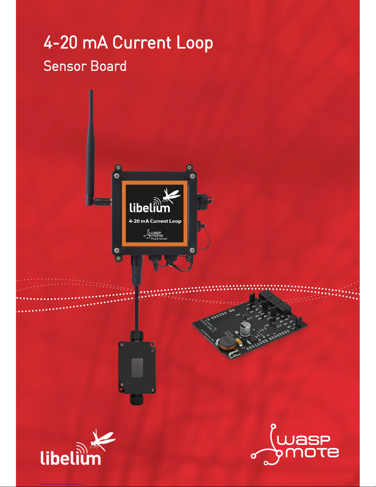
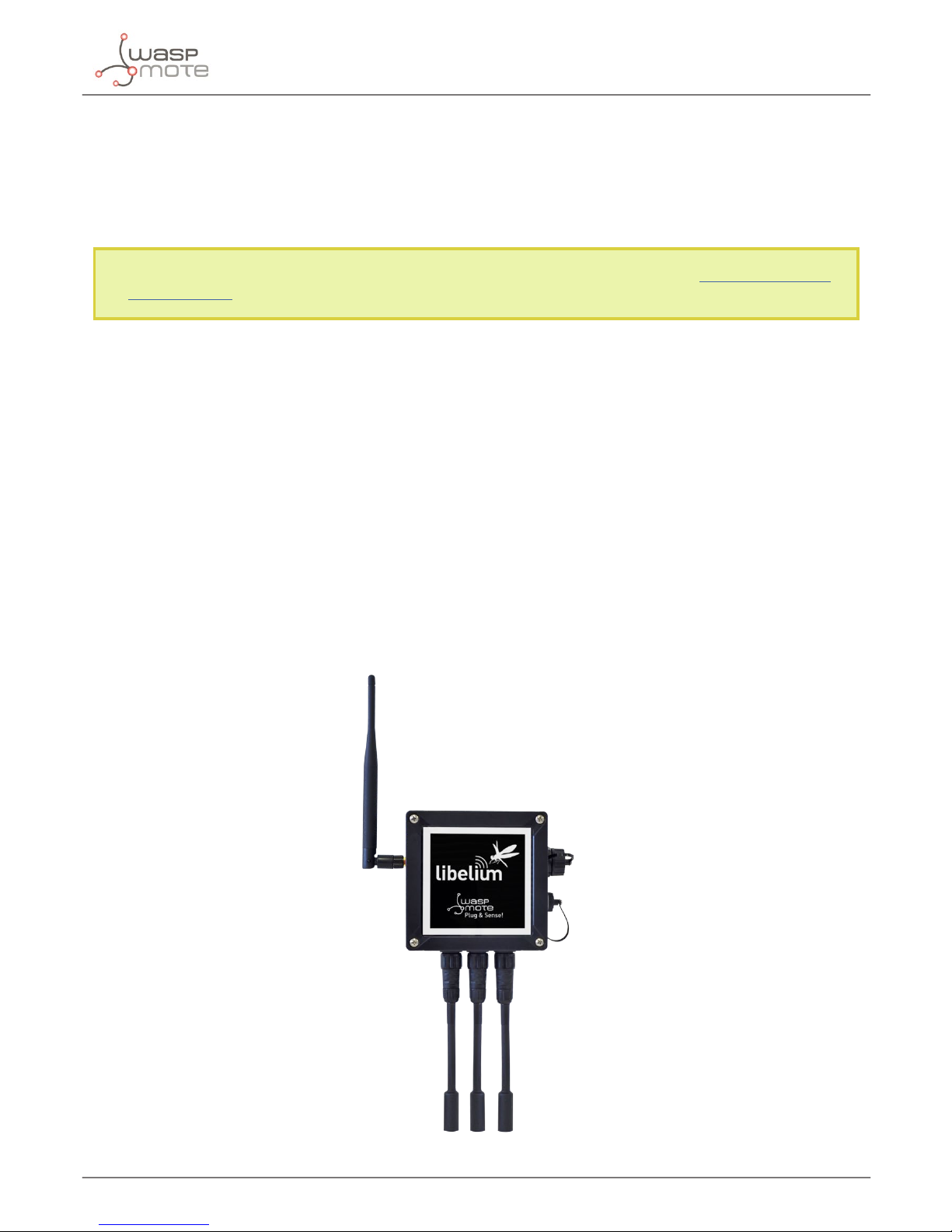
Waspmote Plug & Sense!
2. Waspmote Plug & Sense!
The Waspmote Plug & Sense! line allows you to easily deploy Internet of Things networks in an easy and scalable way, ensuring
minimum maintenance costs. The platform consists of a robust waterproof enclosure with specic external sockets to connect
the sensors, the solar panel, the antenna and even the USB cable in order to reprogram the node. It has been specially designed
to be scalable, easy to deploy and maintain.
Note: For a complete reference guide download the “Waspmote Plug & Sense! Technical Guide” in the Development section of
the Libelium website.
2.1. Features
• Robust waterproof IP65 enclosure
• Add or change a sensor probe in seconds
• Solar powered with internal and external panel options
• Radios available: 802.15.4, 868 MHz, 900 MHz, WiFi, 4G, Sigfox and LoRaWAN
• Over the air programming (OTAP) of multiple nodes at once (via WiFi or 4G radios)
• Special holders and brackets ready for installation in street lights and building fronts
• Graphical and intuitive programming interface Code Generator (coming in 2017)
• Built-in, 3-axes accelerometer
• External, contactless reset with magnet
• External SIM connector for the 4G models
• Fully certied: CE (Europe), FCC (USA), IC (Canada), ANATEL (Brazil), RCM (Australia), PTCRB (USA, cellular connectivity),
AT&T (USA, cellular connectivity)
Figure: Waspmote Plug & Sense!
Page 6
-6-
v7.1
General view
3. General view
This section shows main parts of Waspmote Plug & Sense! and a brief description of each one. In later sections all parts will be
described deeply.
3.1. Specications
• Material: polycarbonate
• Sealing: polyurethane
• Cover screws: stainless steel
• Ingress protection: IP65
• Impact resistance: IK08
• Rated insulation voltage AC: 690 V
• Rated insulation voltage DC: 1000 V
• Heavy metals-free: Yes
• Weatherproof: true - nach UL 746 C
• Ambient temperature (min.): -10 °C
• Ambient temperature (max.): 50 °C
• Approximated weight: 800 g
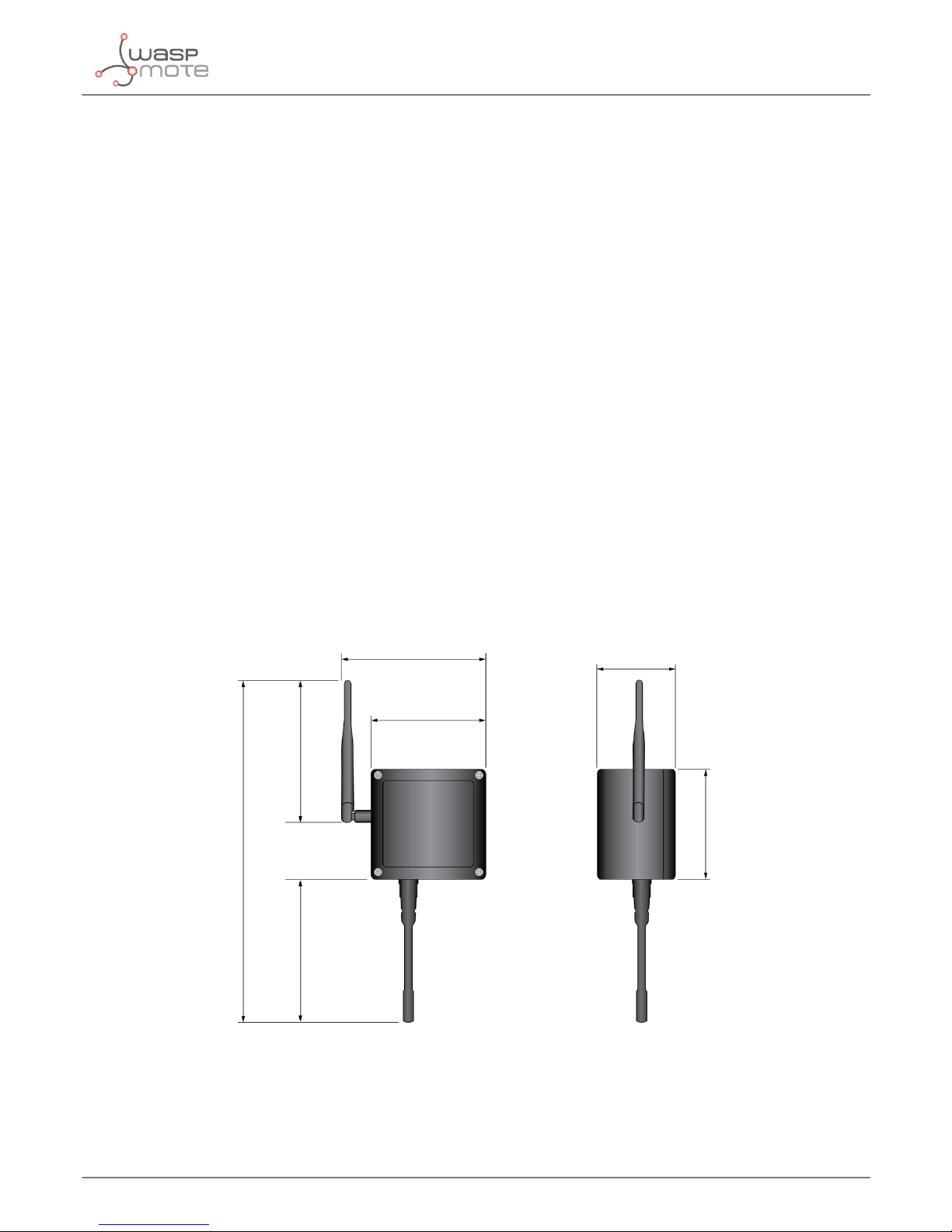
In the pictures included below it is shown a general view of Waspmote Plug & Sense! main parts. Some elements are dedicated
to node control, others are designated to sensor connection and other parts are just identication elements. All of them will be
described along this guide.
164 mm
124 mm
175 mm
410 mm
160 mm
122 mm
85 mm
Figure : Main view of Waspmote Plug & Sense!
Page 7
-7-
v7.1
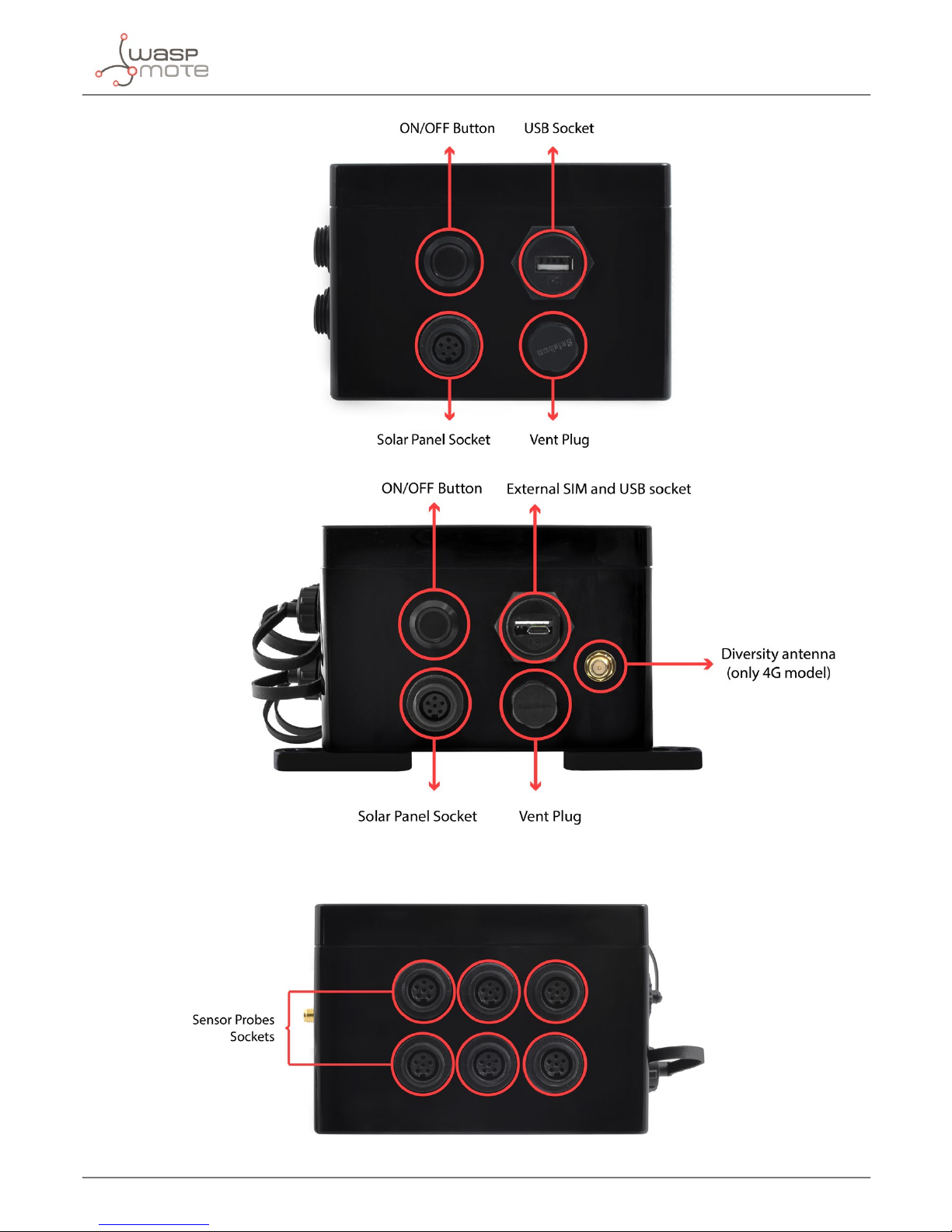
General view
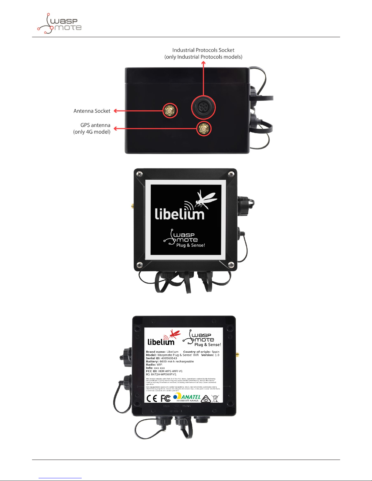
Figure : Control side of the enclosure
Figure : Control side of the enclosure for 4G model
Figure : Sensor side of the enclosure
Page 8
-8-
v7.1
General view
Figure : Antenna side of the enclosure
Figure : Front view of the enclosure
Figure : Back view of the enclosure
Page 9
-9-
v7.1
General view
Figure : Warranty stickers of the enclosure
Important note: Do not handle black stickers seals of the enclosure (Warranty stickers). Their integrity is the proof that Waspmote
Plug & Sense! has not been opened. If they have been handled, damaged or broken, the warranty is automatically void.
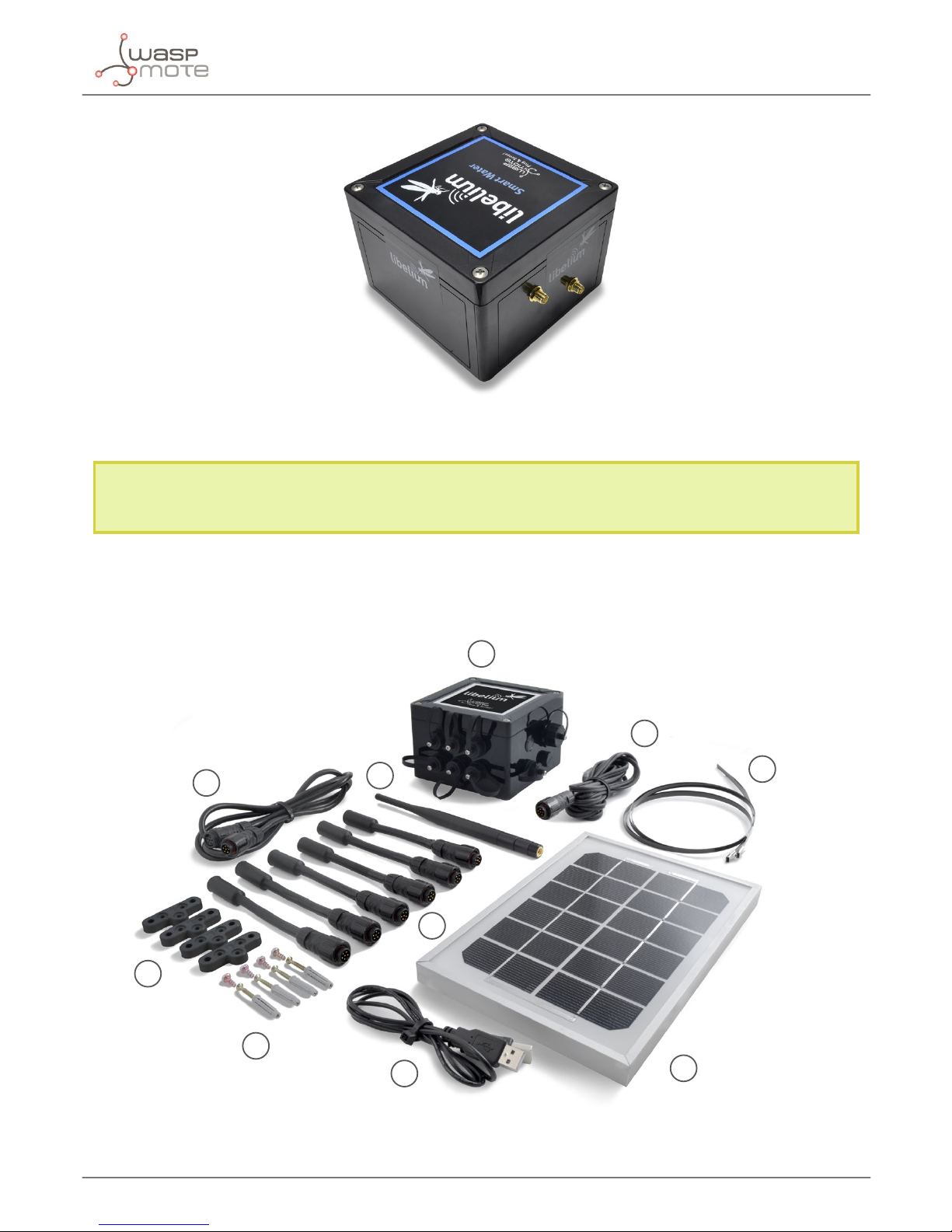
3.2. Parts included
Next picture shows Waspmote Plug & Sense! and all of its elements. Some of them are optional accessories that may not be
included.
1
2
3
4
5
7
6
8
9
10
Figure : Waspmote Plug & Sense! accessories: 1 enclosure, 2 sensor probes, 3 external solar panel, 4 USB cable, 5 antenna, 6 cable ties, 7 mounting feet
(screwed to the enclosure), 8 extension cord, 9 solar panel cable, 10 wall plugs & screws
Page 10
-10-
v7.1
General view
3.3. Identication
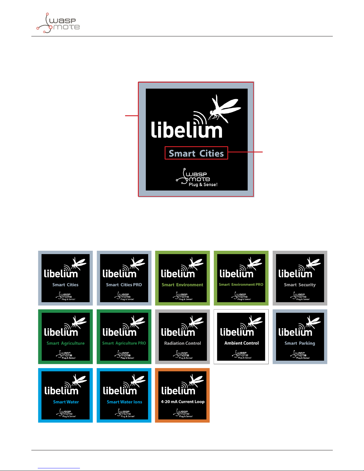
Each Waspmote model is identied by stickers. Next gure shows front sticker.
Model identication colour
Enclosure model
Figure : Front sticker of the enclosure
There are many congurations of Waspmote Plug & Sense! line, all of them identied by one unique sticker. Next image shows
all possibilities.
Figure : Dierent front stickers
Page 11
-11-
v7.1
General view
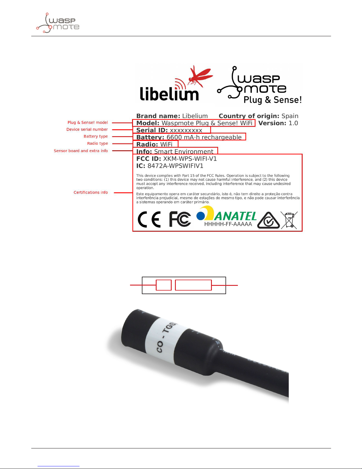
Moreover, Waspmote Plug & Sense! includes a back sticker where it is shown identication numbers, radio MAC addresses, etc.
It is highly recommended to annotate this information and save it for future maintenance. Next gure shows it in detail.
Figure : Back sticker
Sensor probes are identied too by a sticker showing the measured parameter and the sensor manufacturer reference.
CO - TGS2442
Measure parameter
Sensor reference
Figure : Sensor probe identication sticker
Page 12
-12-
v7.1
Sensor probes
4. Sensor probes
Sensor probes can be easily attached by just screwing them into the bottom sockets. This allows you to add new sensing
capabilities to existing networks just in minutes. In the same way, sensor probes may be easily replaced in order to ensure the
lowest maintenance cost of the sensor network.
Figure : Connecting a sensor probe to Waspmote Plug & Sense!
Go to the Plug & Sense! Sensor Guide to know more about our sensor probes.
5. Solar powered
The battery can be recharged using the waterproof USB cable but also the internal or external solar panel options.
The external solar panel is mounted on a 45º holder which ensures the maximum performance of each outdoor installation.
Figure : Waspmote Plug & Sense! powered by an external solar panel
Page 13

-13-
v7.1
Solar powered
For the internal option, the solar panel is embedded on the front of the enclosure, perfect for use where space is a major
challenge.
Figure : Internal solar panel
Figure : Waspmote Plug & Sense! powered by an internal solar panel
Page 14

-14-
v7.1
Programming the Nodes
6. Programming the Nodes
Waspmote Plug & Sense! can be reprogrammed in two ways:
The basic programming is done from the USB port. Just connect the USB to the specic external socket and then to the computer
to upload the new rmware.
Figure : Programming a node
Besides, Libelium is developing a graphical and intuitive programming interface, the Code Generator (coming in 2017).
Figure: Code Generator web application
Page 15

-15-
v7.1
Programming the Nodes
Over the Air Programming (OTAP) is also possible once the node has been installed (via WiFi or 4G radios). With this technique
you can reprogram, wireless, one or more Waspmote sensor nodes at the same time by using a laptop and Meshlium.
Figure : Typical OTAP process
Page 16

-16-
v7.1
Radio interfaces
7. Radio interfaces
Radio Protocol Frequency bands Transmission power Sensitivity Range*
Certication
XBee-PRO 802.15.4 EU 802.15.4 2.4 GHz 10 dBm -100 dBm 750 m CE
XBee-PRO 802.15.4 802.15.4 2.4 GHz 18 dBm -100 dBm 1600 m
FCC, IC, ANATEL,
RCM
XBee 868LP RF 868 MHz 14 dBm -106 dBm 8.4 km CE
XBee 900HP US RF 900 MHz 24 dBm -110 dBm 15.5 km FCC, IC
XBee 900HP BR RF 900 MHz 24 dBm -110 dBm 15.5 km ANATEL
XBee 900HP AU RF 900 MHz 24 dBm -110 dBm 15.5 km RCM
WiFi
WiFi
(HTTP(S), FTP,
TCP, UDP)
2.4 GHz 17 dBm -94 dBm 500 m
CE, FCC, IC,
ANATEL, RCM
4G EU/BR
4G/3G/2G
(HTTP, FTP,
TCP, UDP)
GPS
800, 850, 900, 1800,
2100, 2600 MHz
4G: class 3
(0.2 W, 23 dBm)
4G: -102
dBm
- km - Typical
base station
range
CE, ANATEL
4G US
4G/3G/2G
(HTTP, FTP,
TCP, UDP)
GPS
700, 850, 1700,
1900 MHz
4G: class 3
(0.2 W, 23 dBm)
4G: -103
dBm
- km - Typical
base station
range
FCC, IC, PTCRB,
AT&T
4G AU
4G
(HTTP, FTP,
TCP, UDP)
700, 1800, 2600
MHz
4G: class 3
(0.2 W, 23 dBm)
4G: -102
dBm
- km - Typical
base station
range
RCM
Sigfox EU Sigfox 868 MHz 16 dBm -126 dBm
- km - Typical
base station
range
CE
Sigfox US Sigfox 900 MHz 24 dBm -127 dBm
- km - Typical
base station
range
FCC, IC
LoRaWAN EU LoRaWAN 868 MHz 14 dBm -136 dBm > 15 km CE
LoRaWAN US LoRaWAN 900 MHz 18.5 dBm -136 dBm > 15 km FCC, IC
* Line of sight and Fresnel zone clearance with 5dBi dipole antenna.
Page 17

-17-
v7.1
Industrial Protocols
8. Industrial Protocols
Besides the main radio of Waspmote Plug & Sense!, it is possible to have an Industrial Protocol module as a secondary
communication option. This is oered as an accessory feature.
The available Industrial Protocols are RS-232, RS-485, Modbus (software layer over RS-232 or RS-485) and CAN Bus. This optional
feature is accessible through an additional, dedicated socket on the antenna side of the enclosure.
Figure: Industrial Protocols available on Plug & Sense!
Page 18

-18-
v7.1
Industrial Protocols
Finally, the user can choose between 2 probes to connect the desired Industrial Protocol: A standard DB9 connector and a
waterproof terminal block junction box. These options make the connections on industrial environments or outdoor applications
easier.
Figure: DB9 probe
Figure: Terminal box probe
Page 19

-19-
v7.1
Industrial Protocols
8.1. 4-20 mA Current Loop
The applications for this Plug & Sense! model are focused on adding wireless connectivity to 4-20 mA devices and connecting
them to the Cloud.
Figure: 4-20 mA Current Loop Waspmote Plug & Sense! model
Sensor sockets are congured as shown in the gure below.
Sensor
Socket
Sensor probes allowed for each sensor socket
Board channel Reference
A Channel 1 (type 2) 9270-P, DB9-P
B Channel 2 (type 2) 9270-P, DB9-P
C Channel 3 (type 2) 9270-P, DB9-P
D Channel 4 (type 4) 9270-P, DB9-P
Figure: Sensor sockets configuration for 4-20 mA Current Loop model
Note: For more technical information about each sensor probe go to the Development section on the Libelium website.
Page 20

-20-
v7.1
Introduction
9. Introduction
This guide explains the 4-20 mA Current Loop Sensor Board features and functions. This product was designed for Waspmote
v12 and continues with no changes for Waspmote v15. There are no great variations in this library for our new product line
Waspmote v15, released on October 2016.
Anyway, if you are using previous versions of our products, please use the corresponding guides, available on our Development
website.
You can get more information about the generation change on the document “New generation of Libelium product lines”.
9.1. The standard
The 4-20 mA current loop is one of the most robust sensor signaling standard. Current loops are ideal for data transmission
because of their inherent insensitivity to electrical noise. In a 4-20 mA current loop, all the signaling current ows through all
components; the same current ows even if the wire terminations are less than perfect. All the components in the loop drop
voltage due to the signaling current owing through them. The signaling current is not aected by these voltage drops as long
as the power supply voltage is greater than the sum of the voltage drops around the loop at the maximum signaling current of
20 mA.
Transmitting sensor information via a current loop is particularly useful when the information has to be sent to a remote location
over long distances (500 meters, or more). The loop’s operation is straightforward: a sensor’s output voltage is rst converted to
a proportional current, with 4 mA normally representing the sensor’s zero-level output, and 20 mA representing the sensor’s full
scale output. Then, a receiver at the remote end converts the 4-20 mA current back into a voltage which in turn can be further
processed by a computer or display module.
This list includes some of the most common uses of the standard:
• Sensors and instruments
• Remote transducers
• Monitoring processes
• Data transmission in industrial ambients
Figure : 4-20 mA standard typical connection diagram
9.2. Power Supply
The loop power-supply generally provides all operating power to the transmitter and receiver, and any other loop components
that require a well-regulated DC voltage. In loop-powered applications, the power supply’s internal elements also furnish a path
for closing the series loop. +24 V is still the most widely used power supply voltage in 4-20 mA process monitoring applications.
This is due to the fact that +24 V is also used to power many other instruments and electromechanical components commonly
found in industrial environments. Lower supply voltages, such as +12 V, are also popular since they are used in computer based
systems.
Page 21

-21-
v7.1
Introduction
9.3. Transmitters categories
Depending on the source of current for the loop, devices may be classied as active (supplying power) or passive (relying on
loop power).
9.3.1. Type 2 loop current
Type 2 transmitters are energized by the current loop, where the supply voltage is included in the receptor. The transmitter is
oating and the ground is in the receptor.
Figure : 4-20 mA type 2 connection
9.3.2. Type 3 loop current
Type 3 transmitters have 3 wires powered by the source voltage in them. In this case the transmitter is the power source for the
current loop. The transmitter common is connected to the common of the receptor.
Figure : 4-20 mA type 3 connection
Page 22

-22-
v7.1
Introduction
9.3.3. Type 4 loop current
Type 4 transmitters have 4 wires powered by the source voltage in them. The transmitter powers the current loop and the
receptor acts a oating load.
Figure : 4-20 mA type 4 connection
Page 23

-23-
v7.1
Hardware
10. Hardware
10.1. Electrical characteristics
• Board power voltages: 4.2 V
• Output voltage max: +12 V
• Output current max: 180 mA
• Converting resistance tolerance: 0.1%
• Temperature Range: [0 °C, 85 °C]
• Dimensions: 73.5 x 51 x 1.3 mm
Figure : 4-20 mA Board connected over Waspmote
Page 24

-24-
v7.1
Hardware
10.2. Connection diagram
The 4-20 mA Board for Waspmote has 4 input channels which allow the user to convert signals that come from 3rd party sensors
or devices with this industrial standard. The 4-20 mA Board works with type 2, 3 and 4 current transmitters. Each channel can
be congured for working with these types of connections. If the jumper is moved away, the receptor (the 4-20 Board) will be
congured as oat (type 4 connection).
Figure : 4-20 mA Board diagram of connections
Figure : Channels from 1 to 4 and power supply connections
Page 25

-25-
v7.1
Hardware
10.3. Channel wiring for Plug & Sense!
The 4-20 mA board for Plug & Sense! has the same features as the Waspmote version. The four channels are accessible through
the sensor sockets following this correspondence:
• channel 1 → socket A
• channel 2 → socket B
• channel 3 → socket C
• channel 4 → socket D
However, the transmitter categories cannot be modied on Plug & Sense!. Channels 1, 2 and 3 are predened as type 2, while
channel 4 is type 4 (jumper removed). The user has no access to the channel selection jumper.
Finally, each signal is wired following the next table.
Terminal box probe DB9 probe Signal
1 1 Channel n +
2 2 Channel n -
3 3 Vout +
4 4 Vout -
5 5 -
6 6 -
- 7 -
- 8 -
- 9 -
Figure : 4-20 mA channel wiring for the DB9 and terminal box probes
Page 26

-26-
v7.1
Hardware
10.4. Sensor connection on Plug & Sense!
10.4.1. Terminal box probe
To provide access to the board signals in the Waspmote Plug & Sense! encapsulated line, a waterproof terminal block junction
box is provided as an accessory probe, making the connections on industrial environments or outdoor applications easier.
Figure : Terminal box probe connected to the Plug & Sense! 4-20 mA current loop
Page 27

-27-
v7.1
Hardware
It consists of 2 cable glands and 6 terminal block connectors with screw. The junction box can be easily opened by removing
the four external screws and the cover. Then, the user is able to make the necessary connections using the terminal block
connectors. Finally, the cable glands should be adjusted and the junction box should be closed properly to avoid water ingress.
Figure : Terminal box probe
Note: Please double check the terminal block connections to avoid wrong wirings or short circuits between poles. The Waspmote
Plug & Sense! unit can be seriously damaged. Besides, ensure that the junction box is properly closed to avoid damage in outdoors
applications. Libelium warranty will not cover damages caused by a wrong installation.
10.4.2. DB9 probe
The DB9 connector is commonly used in many applications with data transmission on industrial ambients. Libelium provides
this probe as an accessory with a standard DB9 female connector and a cable with length of 1.5 meters.
Figure : DB9 probe
10.5. Consumption
The consumption of the 4-20 mA Board depends on several factors. When the battery is fully charged, the consumption of the
board is lower due to the DC-DC converter. This DC-DC converter rises the voltage from the battery voltage level to 12 V, so if the
battery level decreases, the energy needed to maintain the 12 V level is higher. The nominal consumption of the board is 8 mA
without sensor. Also, if the 4-20 mA Board is used to power other sensors, the consumption will increase.
Page 28

-28-
v7.1
Hardware
10.6. Connectors
For connecting the 4-20 mA sensors, the 4-20 mA Board includes PTSM connectors. These connectors (PTSM from Phoenix
Contact) allow to assemble the wires of the probe simply by pressing them into it. To remove the wire, press the slot above the
input pin and pull o the wire softly.
Figure : Diagram of a socket extracted from the Phoenix Contact data sheet
10.7. Powering sensors from the 4-20 mA Board
The 4-20 mA Board includes a 12 V output that can be used as power supply for sensors. The majority of 4-20 mA sensor works
in the 9-24 V range. Before connecting a sensor to the 4-20 mA Board, you must be sure that 12 V ts the sensor’s range of the
power supply. If you are going to use all channels, the consumption of the board will increase. It is important to know that the
4-20 mA Board is not designed to power industrial devices such as PLC’s and thermostats: the maximum current output is about
180 mA.
Page 29

-29-
v7.1
Applications
11. Applications
The 4-20 mA Sensor Board allows the user to interface the Waspmote ecosystem with 4-20 mA systems. Waspmote allows to
perform two main applications:
1º- Add wireless connectivity to 4-20 mA devices
Waspmote can be congured to read the information from the bus and send it to the Libelium IoT Gateway using any of the
wireless radio modules available: 802.15.4, 868 MHz, 900 MHz, WiFi, 4G, Sigfox and LoRaWAN, Bluetooth Pro, Bluetooth Low
Energy and RFID/NFC.
Figure : 4-20 mA wireless application
2º- Connect to the Cloud 4-20 mA devices
Waspmote can be congured to read the information coming from the 4-20 mA sensors and send it wirelessly directly to the
Cloud using WiFi, GPRS, GPRS+GPS, 3G and 4G radio interfaces.
Figure : Cloud connection
Page 30

-30-
v7.1
Libelium library
12. Libelium library
It is mandatory to include the 4-20 mA library when using this board. The following line must be introduced at the beginning
of the code:
#include <currentLoop.h>
Waspmote’s API 4-20 mA les:
• currentLoop.cpp
• currentLoop.h
API’s functions
- Public functions:
uint8_t ON(uint8_t powerSupply)
Powers on the 4-20 mA supply (5 V or 12 V)
uint8_t OFF(uint8_t powerSupply)
Powers o the 4-20 mA supply (5 V or 12 V)
int readChannel(uint8_t channel)
Gets the sensor value in integer format
oat readVoltage(uint8_t channel)
Gets the sensor value as a voltage
readCurrent(uint8_t channel, oat offSet)
Gets the sensor value as a current in mA and introduce an
oSet correction factor
oat readCurrent(uint8_t channel)
Gets the sensor value as a current in mA
uint8_t isConnected(uint8_t channel)
Checks if the current loop is well connected
Figure : Table of public functions
When using the Plug & Sense! 4-20 mA model, the correspondence between the board channels and the external sockets is
dened like this:
• channel 1 → socket A
• channel 2 → socket B
• channel 3 → socket C
• channel 4 → socket D
This way, a Plug & Sense! user with a sensor on socket A (channel 1 of the 4-20 mA sensor board) will use the next line to read it:
int value = currentLoopBoard.readChannel(SOCKET_A);
Page 31

-31-
v7.1
Library functions
13. Library functions
13.1. Library constructor
To start using Waspmote 4-20 mA library, an object from class currentLoop must be created. This object, called
currentLoopBoard, is created inside Waspmote 4-20 mA library and it is public to all libraries. It is used through this guide to
show how Waspmote 4-20 mA library works. When creating this constructor, all the variables are dened with an initial value
by default.
13.2. Switching the board on
The 4-20 mA Board includes a 12 V output that can be used to supply sensors, and can be controlled from the library functions,
by a digital pin of Waspmote. The electronic measurement circuits use the 5 V power (so it is always mandatory to switch this
option on), and is necessary to switch on this power supply before getting data from the sensors.
On the other hand, it is only necessary to switch the 12 V on when we want to power 3rd party sensors.
Example of use:
{
// Sets the 5 V switch ON
currentLoopBoard.ON(SUPPLY5V);
delay(100);
// Sets the 12 V switch ON
currentLoopBoard.ON(SUPPLY12V);
delay(100);
}
See an example of use here:
http://www.libelium.com/development/waspmote/examples/4-20ma-01-current-loop-basic-example
13.3. Switching the board o
This function can be used to switch OFF the power supplies of the 4-20 mA Board. The 12 V and 5 V power supplies must be
switched o separately as shown in the next example.
Example of use:
{
// Sets the 5 V switch OFF
currentLoopBoard.OFF(SUPPLY5V);
delay(100);
// Sets the 12 V switch OFF
currentLoopBoard.OFF(SUPPLY12V);
delay(100);
}
Page 32

-32-
v7.1
Library functions
13.4. Reading data
The 4-20 mA library includes the necessary functions to read data in several formats. The 4-20 mA standard sends the sensor
information as a current, and this information can be transformed in voltage with a simple conversion function.
Example of use:
{
// Get the sensor value in integer format (0-1023)
int value = currentLoopBoard.readChannel(CHANNEL1);
USB.print(“Int value read from channel 1: “);
USB.println(value);
// Get the sensor value as a voltage
oat voltage = currentLoopBoard.readVoltage(CHANNEL1);
USB.print(“Voltage value read from channel 1: “);
USB.print(voltage);
USB.println(“V”);
// Get the sensor value as a current in mA
oat current = currentLoopBoard.readCurrent(CHANNEL1);
USB.print(“Current value read from channel 1: “);
USB.print(current);
USB.println(“mA”);
}
Sometimes, it is necessary to introduce a correction factor to correct oset deviations in the measurement process. The next
function can be used for this:
{
// Get the sensor value as a current in mA
oat current = currentLoopBoard.readCurrent(CHANNEL1, OFFSET);
USB.print(“Current value read from channel 1: “);
USB.print(current);
USB.println(“mA”);
}
See an example of use here:
http://www.libelium.com/development/waspmote/examples/4-20ma-01-current-loop-basic-example
13.5. Current loop state
One of the most important features of the 4-20 mA standard is the possibility of detecting a broken wire or failed instrument.
The 4-20 mA library includes a function to detect the current state of the line.
Example of use:
{
if (currentLoopBoard.isConnected(CHANNEL1))
{
// Get the sensor value as a current in mA
current = currentLoopBoard.readCurrent(CHANNEL1);
USB.print(“Current value read from channel 1: “);
USB.print(current, 3);
USB.println(“mA”);
}
else
{
USB.println(“The sensor is not connected...”);
}
}
See an example of use here:
http://www.libelium.com/development/waspmote/examples/4-20ma-02-current-loop-connection-state
Page 33

-33-
v7.1
Real application example
14. Real application example
As a real application we are going to connect a generic 4-20 mA sensor to the 4-20 Sensor Board and power the sensor with the
Board’s 12 V output. This sensor is a type 2 transmitter. Type 2 transmitters are energized by the current loop, where the supply
voltage is included in the receptor. The transmitter voltage is oating and the ground is in the receptor, so it is necessary to
connect the corresponding jumper.
Figure : 4-20 mA sensor connected to the 4-20 mA Board
In the case of Plug & Sense!, the sensor can be connected to channel 1 (which is type 2) using the terminal box probe connected
to socket A. The two sensor wires are connected on positions 1 (channel +) and 2 (channel -).
Figure : 4-20 mA sensor connected to the Plug & Sense! 4-20 mA current loop model
Page 34

-34-
v7.1
Real application example
After connecting the sensor, you only have to upload one of the example codes included in the Waspmote IDE, for instance the
example number one:
http://www.libelium.com/development/waspmote/examples/4-20ma-01-current-loop-basic-example
In the serial monitor you should see that the sensor is transmitting 4 mA. The 4 mA “bottom of span” signal allows the receiver
to detect a broken wire or failed instrument. Remember that in normal operation, a 4-20 mA sensor delivers between 4 and
20 mA. Any current above or below means malfunction.
The constant-current feature of a current loop cancels out voltage drop errors due to long wiring runs (of course this would also
be true if you selected dierent current values for zero and span [e.g., 5-30 mA]).
Figure : Data reception from the 4-20 mA sensor
Page 35

-35-
v7.1
Code examples and extended information
15. Code examples and extended information
For more information about the Waspmote hardware platform go to:
http://www.libelium.com/waspmote
http://www.libelium.com/development/waspmote
In the Waspmote Development section you can nd complete examples:
http://www.libelium.com/development/waspmote/examples
Example:
/*
* ------ [4-20mA_01] Current Loop Basic Example --------
*
* Explanation: This sketch shows how to use the most important
* features of the 4-20 mA Current Loop Board in Waspmote. This
* standard is used to transmit information of sensor over long
* distances. Waspmote uses analog inputs for reading the sensor
* values.
*
* Copyright (C) 2014 Libelium Comunicaciones Distribuidas S.L.
* http://www.libelium.com
*
* This program is free software: you can redistribute it and/or modify
* it under the terms of the GNU General Public License as published by
* the Free Software Foundation, either version 2 of the License, or
* (at your option) any later version.
*
* This program is distributed in the hope that it will be useful,
* but WITHOUT ANY WARRANTY; without even the implied warranty of
* MERCHANTABILITY or FITNESS FOR A PARTICULAR PURPOSE. See the
* GNU General Public License for more details.
*
* You should have received a copy of the GNU General Public License
* along with this program. If not, see <http://www.gnu.org/licenses/>.
*
* Version: 0.1
* Design: David Gascon
* Implementation: Ahmad Saad
*/
//Include this library for using current loop functions
#include <currentLoop.h>
//Instantiate currentLoop object in channel 1
currentLoop sensor(CHANNEL1);
void setup()
{
// Power on the USB for viewing data in the serial monitor
USB.ON();
delay(100);
// Sets the 5 V switch ON
PWR.setSensorPower(SENS_5V, SENS_ON);
delay(100);
}
void loop()
Page 36

-36-
v7.1
Code examples and extended information
{
// Get the sensor value in int format (0-1023)
int value = sensor.readChannel();
USB.print(“Int value read from channel 1: “);
USB.println(value);
// Get the sensor value as a voltage
oat voltage = sensor.readVoltage();
USB.print(“Voltage value rad from channel 1: “);
USB.print(voltage);
USB.println(“V”);
// Get the sensor value as a curren in mA
oat current = sensor.readCurrent();
USB.print(“Current value read from channel 1: “);
USB.print(current);
USB.println(“mA”);
USB.println(“***************************************”);
USB.print(“\n”);
//Delay after reading
delay(2500);
}
Page 37

-37-
v7.1
API changelog
16. API changelog
Keep track of the software changes on this link:
www.libelium.com/development/waspmote/documentation/changelog/#4_20_mA
Page 38

-38-
v7.1
Documentation changelog
17. Documentation changelog
From v7.0 to v7.1:
• Added references to the integration of Industrial Protocols for Plug & Sense!
Page 39

-39-
v7.1
Certications
18. Certications
Libelium oers 2 types of IoT sensor platforms, Waspmote OEM and Plug & Sense!:
• Waspmote OEM is intended to be used for research purposes or as part of a major product so it needs nal certication on
the client side. More info at: www.libelium.com/products/waspmote
• Plug & Sense! is the line ready to be used out-of-the-box. It includes market certications. See below the specic list of
regulations passed. More info at: www.libelium.com/products/plug-sense
Besides, Meshlium, our multiprotocol router for the IoT, is also certied with the certications below. Get more info at:
www.libelium.com/products/meshlium
List of certications for Plug & Sense! and Meshlium:
• CE (Europe)
• FCC (US)
• IC (Canada)
• ANATEL (Brazil)
• RCM (Australia)
• PTCRB (cellular certication for the US)
• AT&T (cellular certication for the US)
Figure : Certications of the Plug & Sense! product line
You can nd all the certication documents at:
www.libelium.com/certications
 Loading...