

Page 1
Smart Cities PRO
Technical Guide
Page 2

-2-
v7.3
Index
Document version: v7.3 - 11/2017
© Libelium Comunicaciones Distribuidas S.L.
INDEX
1. General ................................................................................................................................... 5
1.1. General and safety information ...................................................................................................... 5
1.2. Conditions of use .............................................................................................................................. 6
2. New version: Smart Cities PRO v3.0 ....................................................................................7
3. Waspmote Plug & Sense! ...................................................................................................... 8
3.1. Features ............................................................................................................................................. 8
3.2. General view ...................................................................................................................................... 9
3.3. Specications ..................................................................................................................................... 9
3.4. Parts included .................................................................................................................................. 12
3.5. Identication .................................................................................................................................... 13
3.6. Sensor probes ................................................................................................................................. 15
3.7. Solar powered ................................................................................................................................. 16
3.8. External Battery Module ................................................................................................................ 18
3.9. Programming the Nodes ................................................................................................................ 19
3.10. Program in minutes ...................................................................................................................... 20
3.11. Radio interfaces ............................................................................................................................ 21
3.12. Industrial Protocols ...................................................................................................................... 22
3.13. GPS ................................................................................................................................................. 24
3.14. Models ............................................................................................................................................ 25
3.14.1. Smart Cities PRO ...............................................................................................................26
4. Hardware .............................................................................................................................28
4.1. General description ........................................................................................................................ 28
4.2. Specications ................................................................................................................................... 28
4.3. Electrical characteristics ................................................................................................................. 28
5. Sensors ................................................................................................................................. 29
5.1. Temperature, Humidity and Pressure Sensor ............................................................................. 29
5.1.1. Specications .......................................................................................................................29
5.1.2. Measurement process ........................................................................................................30
5.1.3. Socket ...................................................................................................................................31
5.2. Ultrasound sensor probe (MaxSonar® from MaxBotix™) ......................................................... 32
5.2.1. Specications .......................................................................................................................32
5.2.2. Measurement Process ........................................................................................................34
5.2.3. Socket ...................................................................................................................................34
5.3. Luminosity (Luxes accuracy) Sensor ............................................................................................. 35
5.3.1. Specications .......................................................................................................................35
5.3.2. Measurement process ........................................................................................................35
5.3.3. Socket ...................................................................................................................................35
5.4. Particle Matter (PM1 / PM2.5 / PM10) - Dust Sensor .................................................................. 36
Page 3

-3-
v7.3
Index
5.4.1. Specications .......................................................................................................................36
5.4.2. Particle matter: the parameter ..........................................................................................37
5.4.3. Measurement process ........................................................................................................37
5.5. Noise / Sound Level Sensor ........................................................................................................... 38
5.5.1. Specications of the Sound Level Sensor probe .............................................................38
5.5.2. Specications of the enclosure ..........................................................................................38
5.5.3. Sound pressure level measurement .................................................................................38
5.5.4. Equivalent continuous sound level ...................................................................................39
5.5.5. The A-weighting ...................................................................................................................39
5.5.6. International standard IEC 61672-1:2013 ........................................................................40
5.5.7. Measurement process ........................................................................................................40
5.5.8. Calibration Tests ..................................................................................................................40
5.5.9. Mounting the Noise / Sound Level Sensor and supplying power .................................43
5.6. Carbon Monoxide (CO) Gas Sensor for high concentrations [Calibrated] ............................... 48
5.6.1. Specications .......................................................................................................................48
5.6.2. Cross-sensitivity data ..........................................................................................................49
5.7. Carbon Monoxide (CO) Gas Sensor for low concentrations [Calibrated] ................................ 50
5.7.1. Specications .......................................................................................................................50
5.7.2. Cross-sensitivity data ..........................................................................................................51
5.8. Carbon Dioxide (CO2) Gas Sensor [Calibrated] ............................................................................ 52
5.8.1. Specications .......................................................................................................................52
5.9. Molecular Oxygen (O2) Gas Sensor [Calibrated] .......................................................................... 53
5.9.1. Specications .......................................................................................................................53
5.10. Ozone (O3) Gas Sensor [Calibrated] ............................................................................................ 54
5.10.1. Specications .....................................................................................................................54
5.10.2. Cross-sensitivity data ........................................................................................................55
5.11. Nitric Oxide (NO) Gas Sensor for low concentrations
[Calibrated] ............................................................................................................................................. 56
5.11.1. Specications .....................................................................................................................56
5.11.2. Cross-sensitivity data ........................................................................................................57
5.12. Nitric Dioxide (NO2) high accuracy Gas Sensor
[Calibrated] ............................................................................................................................................. 58
5.12.1. Specications .....................................................................................................................58
5.12.2. Cross-sensitivity data ........................................................................................................59
5.13. Sulfur Dioxide (SO2) high accuracy Gas Sensor [Calibrated] ................................................... 60
5.13.1. Specications .....................................................................................................................60
5.13.2. Cross-sensitivity data ........................................................................................................61
5.14. Ammonia (NH3) Gas Sensor for low concentrations [Calibrated] ........................................... 62
5.14.1. Specications .....................................................................................................................62
5.14.2. Cross-sensitivity data ........................................................................................................63
5.15. Ammonia (NH3) Gas Sensor for high concentrations [Calibrated] .......................................... 64
5.15.1. Specications .....................................................................................................................64
5.15.2. Cross-sensitivity data ........................................................................................................65
5.16. Methane (CH4) and Combustible Gas Sensor
Page 4

-4-
v7.3
[Calibrated] ............................................................................................................................................. 66
5.16.1. Specications .....................................................................................................................66
5.16.2. Sensitivity data ..................................................................................................................67
5.17. Molecular Hydrogen (H2) Gas Sensor [Calibrated] .................................................................... 68
5.17.1. Specications .....................................................................................................................68
5.17.2. Cross-sensitivity data ........................................................................................................69
5.18. Hydrogen Sulde (H2S) Gas Sensor [Calibrated] ....................................................................... 70
5.18.1. Specications .....................................................................................................................70
5.18.2. Cross-sensitivity data ........................................................................................................71
5.19. Hydrogen Chloride (HCl) Gas Sensor [Calibrated] .................................................................... 72
5.19.1. Specications .....................................................................................................................72
5.19.2. Cross-sensitivity data ........................................................................................................73
5.20. Hydrogen Cyanide (HCN) Gas Sensor [Calibrated] ................................................................... 74
5.20.1. Specications .....................................................................................................................74
5.20.2. Cross-sensitivity data ........................................................................................................75
5.21. Phosphine (PH3) Gas Sensor [Calibrated] .................................................................................. 76
5.21.1. Specications .....................................................................................................................76
5.21.2. Cross-sensitivity data ........................................................................................................77
5.22. Ethylene Oxide (ETO) Gas Sensor [Calibrated] .......................................................................... 78
5.22.1. Specications .....................................................................................................................78
5.22.2. Cross-sensitivity data ........................................................................................................79
5.23. Chlorine (Cl2) Gas Sensor [Calibrated] ........................................................................................ 80
5.23.1. Specications .....................................................................................................................80
5.23.2. Cross-sensitivity data ........................................................................................................81
5.24. Important notes for Calibrated Sensors .................................................................................... 82
6. Board conguration and programming ........................................................................... 83
6.1. Hardware conguration ................................................................................................................ 83
6.2. API ..................................................................................................................................................... 83
6.2.1. Before starting to program ................................................................................................83
6.2.2. Gases sensors ......................................................................................................................83
6.2.3. Temperature, humidity and pressure sensor (BME280) ................................................84
6.2.4. Luxes sensor ........................................................................................................................84
6.2.5. Ultrasound sensor ...............................................................................................................85
7. Consumption ....................................................................................................................... 86
7.1. Consumption table ......................................................................................................................... 86
8. API changelog ...................................................................................................................... 87
9. Documentation changelog ................................................................................................88
10. Certications ..................................................................................................................... 89
11. Maintenance ......................................................................................................................90
12. Disposal and recycling ...................................................................................................... 91
Index
Page 5

-5-
v7.3
General
1. General
Important:
• All documents and any examples they contain are provided as-is and are subject to change without notice.
Except to the extent prohibited by law, Libelium makes no express or implied representation or warranty of
any kind with regard to the documents, and specically disclaims the implied warranties and conditions of
merchantability and tness for a particular purpose.
• The information on Libelium’s websites has been included in good faith for general informational purposes
only. It should not be relied upon for any specic purpose and no representation or warranty is given as to its
accuracy or completeness.
1.1. General and safety information
• In this section, the term “Waspmote” encompasses both the Waspmote device itself and its modules and
sensor boards.
• Read through the document “General Conditions of Libelium Sale and Use”.
• Do not allow contact of metallic objects with the electronic part to avoid injuries and burns.
• NEVER submerge the device in any liquid.
• Keep the device in a dry place and away from any liquid which may spill.
• Waspmote consists of highly sensitive electronics which is accessible to the exterior, handle with great care
and avoid bangs or hard brushing against surfaces.
• Check the product specications section for the maximum allowed power voltage and amperage range and
consequently always use a current transformer and a battery which works within that range. Libelium is only
responsible for the correct operation of the device with the batteries, power supplies and chargers which it
supplies.
• Keep the device within the specied range of temperatures in the specications section.
• Do not connect or power the device with damaged cables or batteries.
• Place the device in a place only accessible to maintenance personnel (a restricted area).
• Keep children away from the device in all circumstances.
• If there is an electrical failure, disconnect the main switch immediately and disconnect that battery or any
other power supply that is being used.
• If using a car lighter as a power supply, be sure to respect the voltage and current data specied in the “Power
Supplies” section.
• If using a battery in combination or not with a solar panel as a power supply, be sure to use the voltage and
current data specied in the “Power supplies” section.
• If a software or hardware failure occurs, consult the Libelium Web Development section.
• Check that the frequency and power of the communication radio modules together with the integrated
antennas are allowed in the area where you want to use the device.
• Waspmote is a device to be integrated in a casing so that it is protected from environmental conditions such
as light, dust, humidity or sudden changes in temperature. The board supplied “as is” is not recommended for
a nal installation as the electronic components are open to the air and may be damaged.
Page 6

-6-
v7.3
General
1.2. Conditions of use
• Read the “General and Safety Information” section carefully and keep the manual for future consultation.
• Use Waspmote in accordance with the electrical specications and the environment described in the “Electrical
Data” section of this manual.
• Waspmote and its components and modules are supplied as electronic boards to be integrated within a nal
product. This product must contain an enclosure to protect it from dust, humidity and other environmental
interactions. In the event of outside use, this enclosure must be rated at least IP-65.
• Do not place Waspmote in contact with metallic surfaces; they could cause short-circuits which will permanently
damage it.
Further information you may need can be found at http://www.libelium.com/development/waspmote
The “General Conditions of Libelium Sale and Use” document can be found at:
http://www.libelium.com/development/waspmote/technical_service
Page 7

-7-
v7.3
New version: Smart Cities PRO v3.0
2. New version: Smart Cities PRO v3.0
This guide explains the new Smart Cities Sensor Board v3.0. This board was designed for our new product lines
Waspmote v15 and Plug & Sense! v15, released on October 2016.
The previous version of this board (Smart Cities v2.0) was designed for Waspmote v12 and Plug & Sense! v12, and
it is NOT recommended to mix product generations. If you are using previous versions of our products, please use
the corresponding guides, available on our Development website.
You can get more information about the generation change on the document “New generation of Libelium product
lines”.
Dierences of Smart Cities PRO v3.0 with the previous version:
• Added the new Noise Level Sensor, able to read LeqA (integrated equivalent continuous sound level,
A-weighted) in dBA. The sensor achieves high accuracy in a wide range of frequencies.
• I2C sockets allow the connection of digital sensors, even gas sensors from Gases PRO, Temperature, Humidity
and Pressure sensor or Luxes and Ultrasound sensors.
• The Particle Matter – Dust Sensor (PM1 / PM2.5 / PM10) is now available on this board.
• New connectors to improve the Plug & Sense! wiring, making it more robust.
• Added an I2C isolator chip to avoid aecting to the Waspmote I2C bus.
Page 8
-8-
v7.3
Waspmote Plug & Sense!
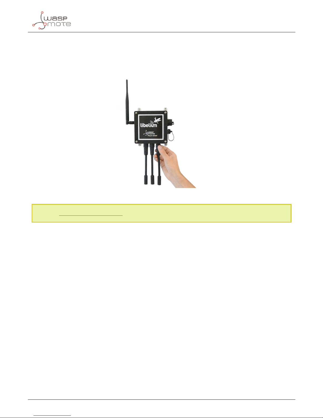
3. Waspmote Plug & Sense!
The Waspmote Plug & Sense! line allows you to easily deploy Internet of Things networks in an easy and scalable
way, ensuring minimum maintenance costs. The platform consists of a robust waterproof enclosure with specic
external sockets to connect the sensors, the solar panel, the antenna and even the USB cable in order to reprogram
the node. It has been specially designed to be scalable, easy to deploy and maintain.
Note: For a complete reference guide download the “Waspmote Plug & Sense! Technical Guide” in the Development
section of the Libelium website.
3.1. Features
• Robust waterproof IP65 enclosure
• Add or change a sensor probe in seconds
• Solar powered with internal and external panel options
• Radios available: 802.15.4, 868 MHz, 900 MHz, WiFi, 4G, Sigfox and LoRaWAN
• Over the air programming (OTAP) of multiple nodes at once (via WiFi or 4G radios)
• Special holders and brackets ready for installation in street lights and building fronts
• Graphical and intuitive interface Programming Cloud Service
• Built-in, 3-axes accelerometer
• External, contactless reset with magnet
• Optional industrial protocols: RS-232, RS-485, Modbus, CAN Bus
• Optional GPS receiver
• Optional External Battery Module
• External SIM connector for the 4G models
• Fully certied: CE (Europe), FCC (USA), IC (Canada), ANATEL (Brazil), RCM (Australia), PTCRB (USA, cellular
connectivity), AT&T (USA, cellular connectivity)
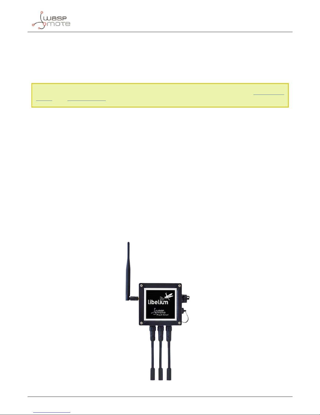
Figure: Waspmote Plug & Sense!
Page 9
-9-
v7.3
Waspmote Plug & Sense!
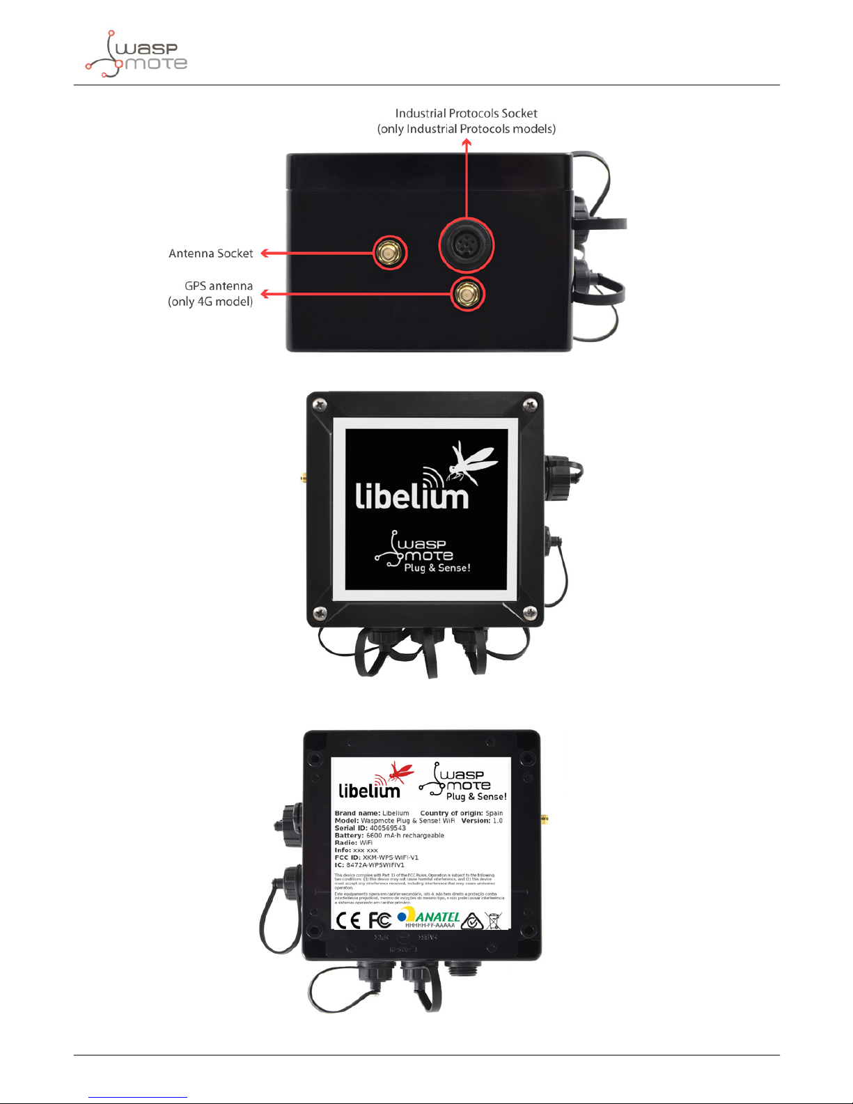
3.2. General view
This section shows main parts of Waspmote Plug & Sense! and a brief description of each one. In later sections
all parts will be described deeply.
3.3. Specications
• Material: polycarbonate
• Sealing: polyurethane
• Cover screws: stainless steel
• Ingress protection: IP65
• Impact resistance: IK08
• Rated insulation voltage AC: 690 V
• Rated insulation voltage DC: 1000 V
• Heavy metals-free: Yes
• Weatherproof: true - nach UL 746 C
• Ambient temperature (min.): -30 °C*
• Ambient temperature (max.): 70 °C*
• Approximated weight: 800 g
* Temporary extreme temperatures are supported. Regular recommended usage: -20, +60 ºC.
In the pictures included below it is shown a general view of Waspmote Plug & Sense! main parts. Some elements
are dedicated to node control, others are designated to sensor connection and other parts are just identication
elements. All of them will be described along this guide.
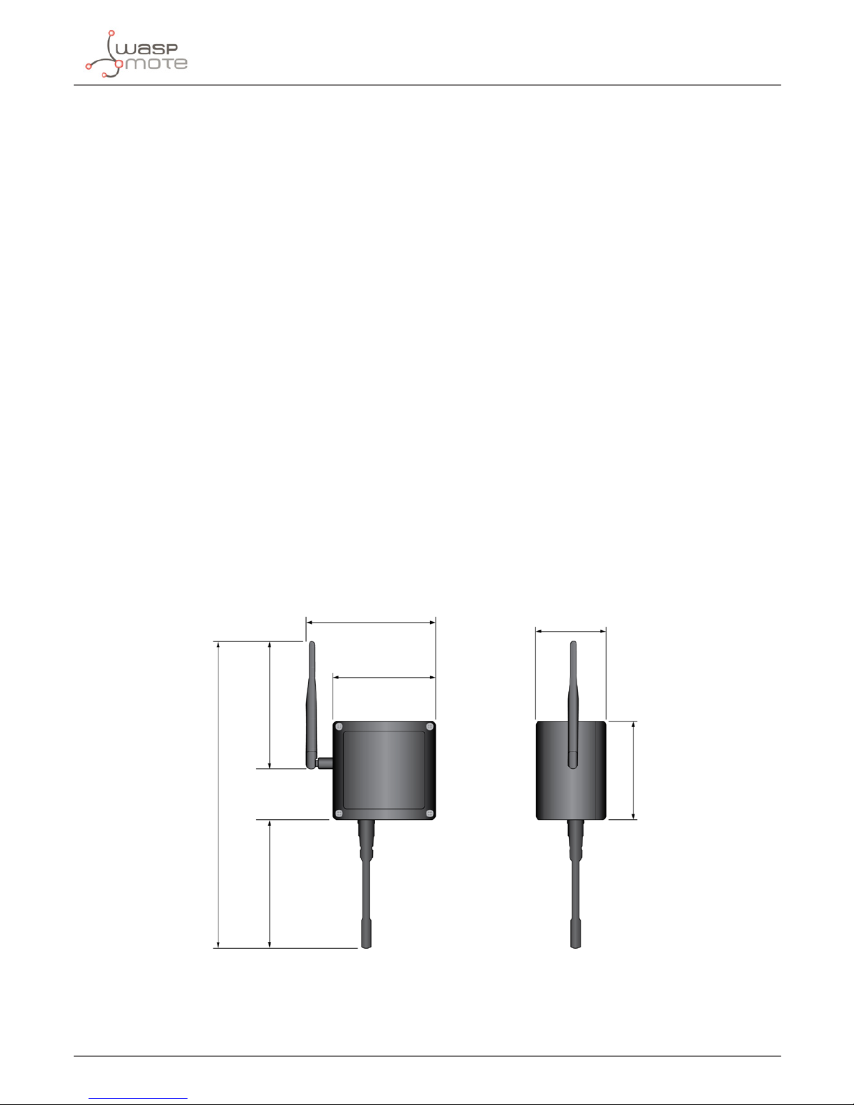
164 mm
124 mm
175 mm
410 mm
160 mm
122 mm
85 mm
Figure: Main view of Waspmote Plug & Sense!
Page 10
-10-
v7.3
Waspmote Plug & Sense!
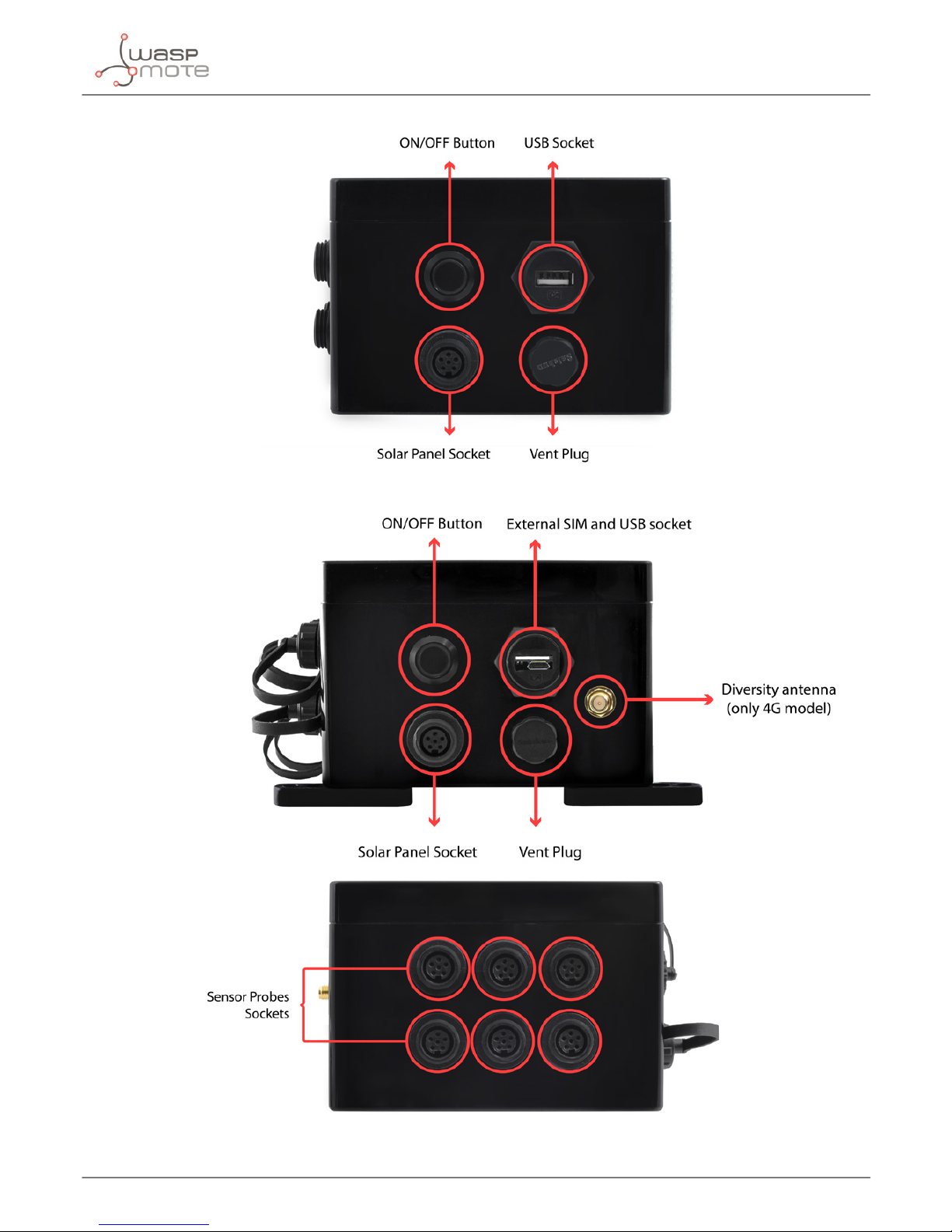
Figure: Control side of the enclosure
Figure: Control side of the enclosure for 4G model
Figure: Sensor side of the enclosure
Page 11
-11-
v7.3
Waspmote Plug & Sense!
Figure: Antenna side of the enclosure
Figure: Front view of the enclosure
Figure: Back view of the enclosure
Page 12
-12-
v7.3
Waspmote Plug & Sense!
Figure: Warranty stickers of the enclosure
Important note: Do not handle black stickers seals of the enclosure (Warranty stickers). Their integrity is the proof
that Waspmote Plug & Sense! has not been opened. If they have been handled, damaged or broken, the warranty is
automatically void.
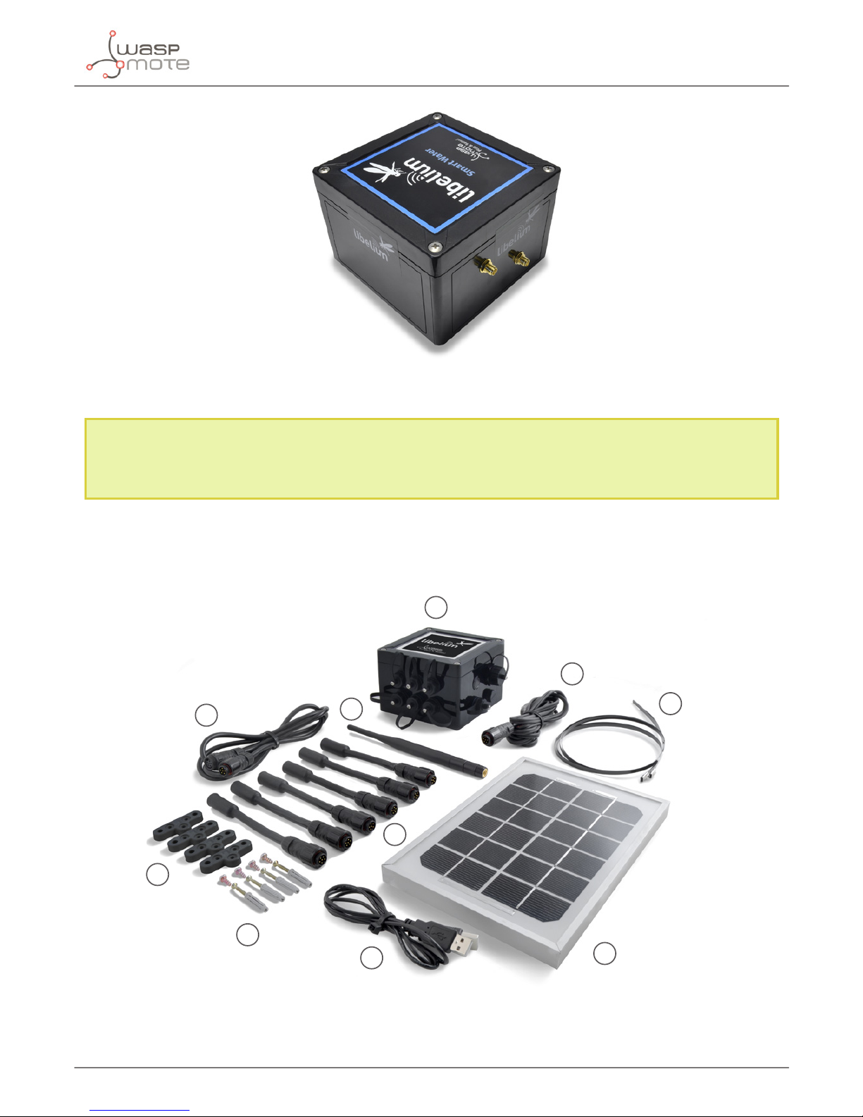
3.4. Parts included
Next picture shows Waspmote Plug & Sense! and all of its elements. Some of them are optional accessories that
may not be included.
1
2
3
4
5
7
6
8
9
10
Figure: Waspmote Plug & Sense! accessories: 1 enclosure, 2 sensor probes, 3 external solar panel, 4 USB cable, 5 antenna, 6 cable ties,
7 mounting feet (screwed to the enclosure), 8 extension cord, 9 solar panel cable, 10 wall plugs & screws
Page 13
-13-
v7.3
Waspmote Plug & Sense!
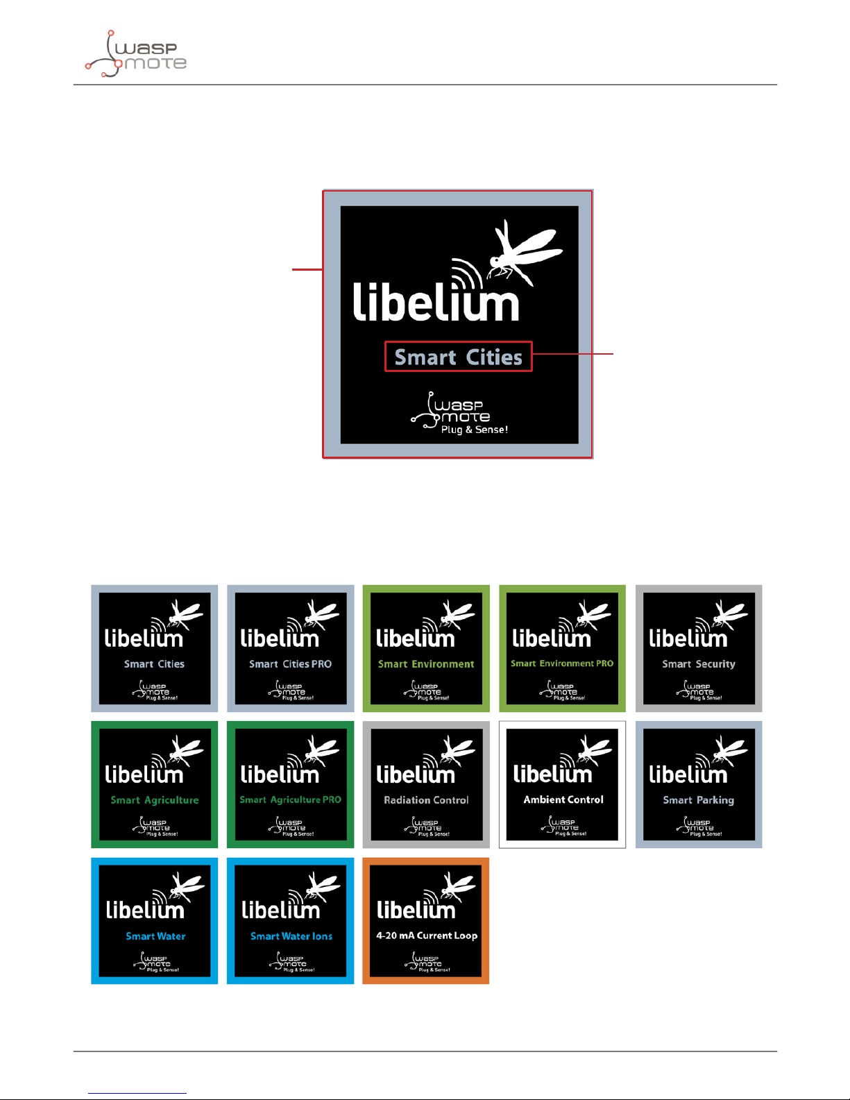
3.5. Identication
Each Waspmote model is identied by stickers. Next gure shows front sticker.
Model identication colour
Enclosure model
Figure: Front sticker of the enclosure
There are many congurations of Waspmote Plug & Sense! line, all of them identied by one unique sticker. Next
image shows all possibilities.
Figure: Dierent front stickers
Page 14
-14-
v7.3
Waspmote Plug & Sense!
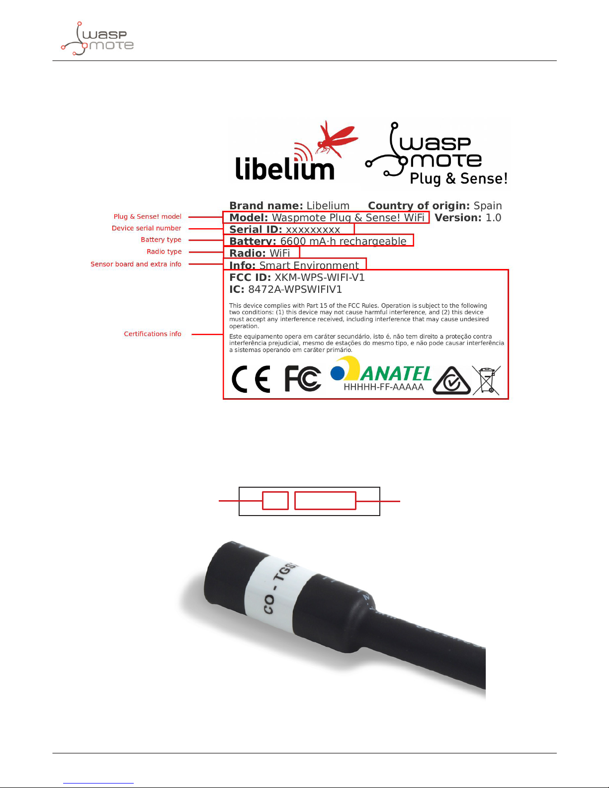
Moreover, Waspmote Plug & Sense! includes a back sticker where it is shown identication numbers, radio MAC
addresses, etc. It is highly recommended to annotate this information and save it for future maintenance. Next
gure shows it in detail.
Figure: Back sticker
Sensor probes are identied too by a sticker showing the measured parameter and the sensor manufacturer
reference.
CO - TGS2442
Measure
parameter
Sensor
reference
Figure: Sensor probe identication sticker
Page 15
-15-
v7.3
Waspmote Plug & Sense!
3.6. Sensor probes
Sensor probes can be easily attached by just screwing them into the bottom sockets. This allows you to add new
sensing capabilities to existing networks just in minutes. In the same way, sensor probes may be easily replaced
in order to ensure the lowest maintenance cost of the sensor network.
Figure: Connecting a sensor probe to Waspmote Plug & Sense!
Go to the Plug & Sense! Sensor Guide to know more about our sensor probes.
Page 16
-16-
v7.3
Waspmote Plug & Sense!
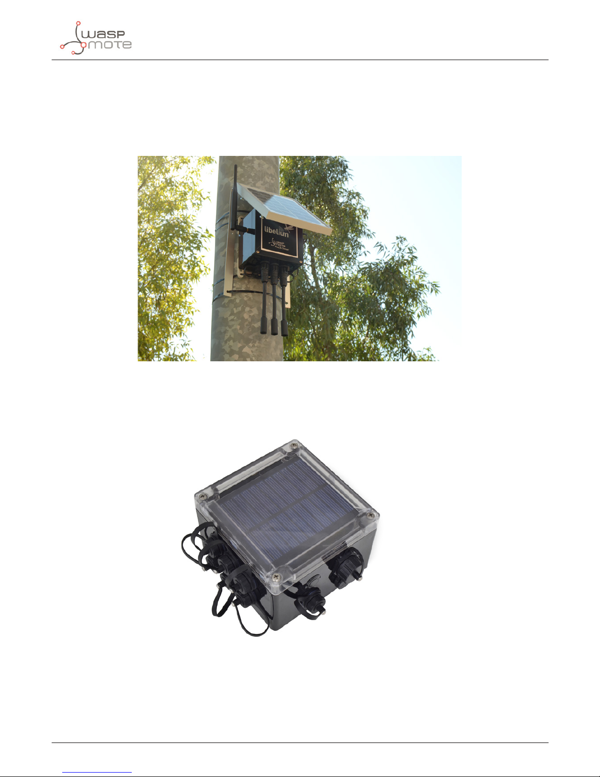
3.7. Solar powered
The battery can be recharged using the waterproof USB cable but also the internal or external solar panel options.
The external solar panel is mounted on a 45º holder which ensures the maximum performance of each outdoor
installation.
Figure: Waspmote Plug & Sense! powered by an external solar panel
For the internal option, the solar panel is embedded on the front of the enclosure, perfect for use where space is
a major challenge.
Figure: Internal solar panel
Page 17

-17-
v7.3
Waspmote Plug & Sense!
Figure: Waspmote Plug & Sense! powered by an internal solar panel
Page 18
-18-
v7.3
Waspmote Plug & Sense!
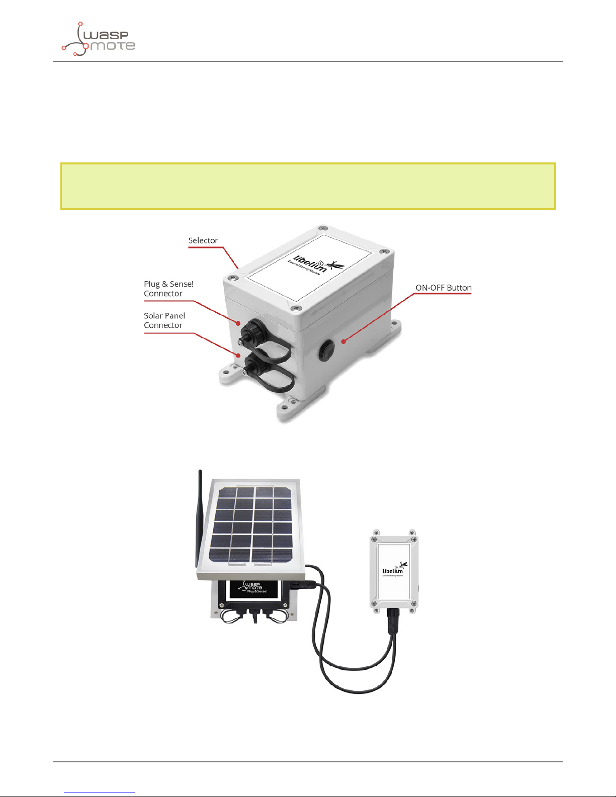
3.8. External Battery Module
The External Battery Module (EBM) is an accessory to extend the battery life of Plug & Sense!. The extension
period may be from months to years depending on the sleep cycle and radio activity. The daily charging period is
selectable among 5, 15 and 30 minutes with a selector switch and it can be combined with a solar panel to extend
even more the node’s battery lifetime.
Note: Nodes using solar panel can keep using it through the External Battery Module (EBM). The EBM is
connected to the solar panel connector of Plug & Sense! and the solar panel unit is connected to the solar
panel connector of the EBM.
Figure: Plug & Sense! with External Battery Module
Figure: Plug & Sense! with External Battery Module and solar panel
Page 19
-19-
v7.3
Waspmote Plug & Sense!
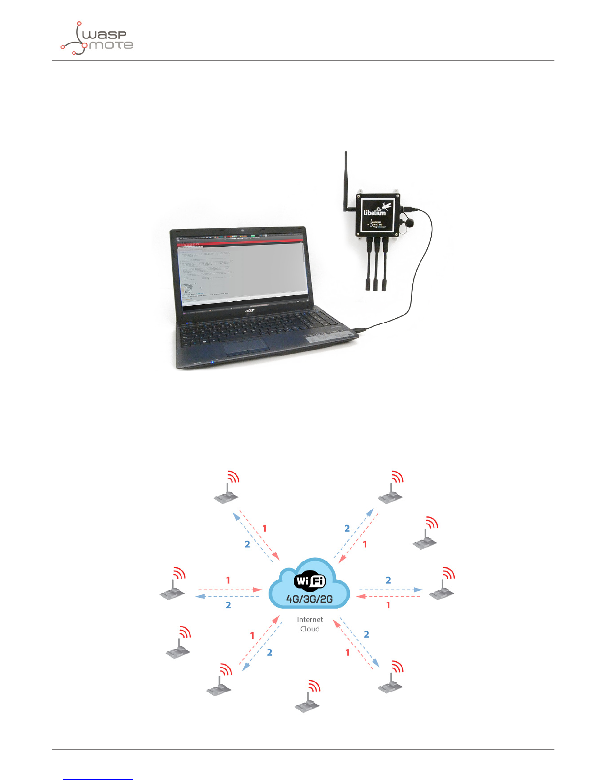
3.9. Programming the Nodes
Waspmote Plug & Sense! can be reprogrammed in two ways:
The basic programming is done from the USB port. Just connect the USB to the specic external socket and then
to the computer to upload the new rmware.
Figure: Programming a node
Over the Air Programming (OTAP) is also possible once the node has been installed (via WiFi or 4G radios). With
this technique you can reprogram, wireless, one or more Waspmote sensor nodes at the same time by using a
laptop and Meshlium.
Figure: Typical OTAP process
Page 20
-20-
v7.3
Waspmote Plug & Sense!
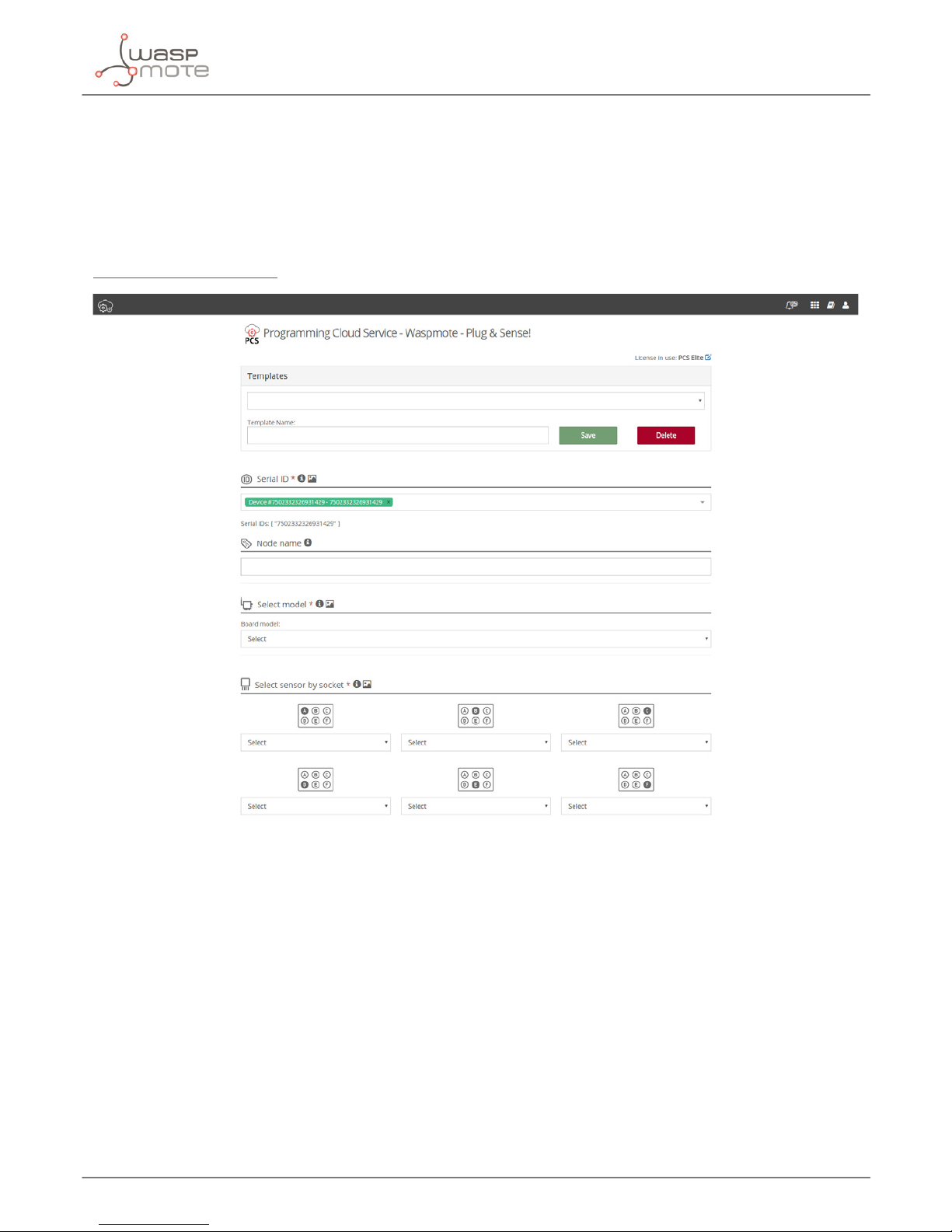
3.10. Program in minutes
The Programming Cloud Service is an intuitive graphic interface which creates code automatically. The user just
needs to to ll a web form to obtain binaries for Plug & Sense!. Advanced programming options are available,
depending on the license selected.
Check how easy it is to handle the Programming Cloud Service at:
https://cloud.libelium.com/
Figure: Programming Cloud Service
Page 21

-21-
v7.3
Waspmote Plug & Sense!
3.11. Radio interfaces
Radio Protocol
Frequency
bands
Transmission
power
Sensitivity Range*
Certication
XBee-PRO 802.15.4
EU
802.15.4 2.4 GHz 10 dBm -100 dBm 750 m CE
XBee-PRO 802.15.4 802.15.4 2.4 GHz 18 dBm -100 dBm 1600 m
FCC, IC, ANATEL,
RCM
XBee 868LP RF 868 MHz 14 dBm -106 dBm 8.4 km CE
XBee 900HP US RF 900 MHz 24 dBm -110 dBm 15.5 km FCC, IC
XBee 900HP BR RF 900 MHz 24 dBm -110 dBm 15.5 km ANATEL
XBee 900HP AU RF 900 MHz 24 dBm -110 dBm 15.5 km RCM
WiFi
WiFi
(HTTP(S),
FTP, TCP,
UDP)
2.4 GHz 17 dBm -94 dBm 500 m
CE, FCC, IC,
ANATEL, RCM
4G EU/BR
4G/3G/2G
(HTTP, FTP,
TCP, UDP)
GPS
800, 850, 900,
1800, 2100, 2600
MHz
4G: class 3
(0.2 W, 23 dBm)
4G: -102
dBm
- km - Typical
base station
range
CE, ANATEL
4G US
4G/3G/2G
(HTTP, FTP,
TCP, UDP)
GPS
700, 850, 1700,
1900 MHz
4G: class 3
(0.2 W, 23 dBm)
4G: -103
dBm
- km - Typical
base station
range
FCC, IC, PTCRB,
AT&T
4G AU
4G
(HTTP, FTP,
TCP, UDP)
700, 1800, 2600
MHz
4G: class 3
(0.2 W, 23 dBm)
4G: -102
dBm
- km - Typical
base station
range
RCM
Sigfox EU Sigfox 868 MHz 16 dBm -126 dBm
- km - Typical
base station
range
CE
Sigfox US Sigfox 900 MHz 24 dBm -127 dBm
- km - Typical
base station
range
FCC, IC
LoRaWAN EU LoRaWAN 868 MHz 14 dBm -136 dBm > 15 km CE
LoRaWAN US LoRaWAN 900 MHz 18.5 dBm -136 dBm > 15 km FCC, IC
* Line of sight and Fresnel zone clearance with 5dBi dipole antenna.
Page 22
-22-
v7.3
Waspmote Plug & Sense!
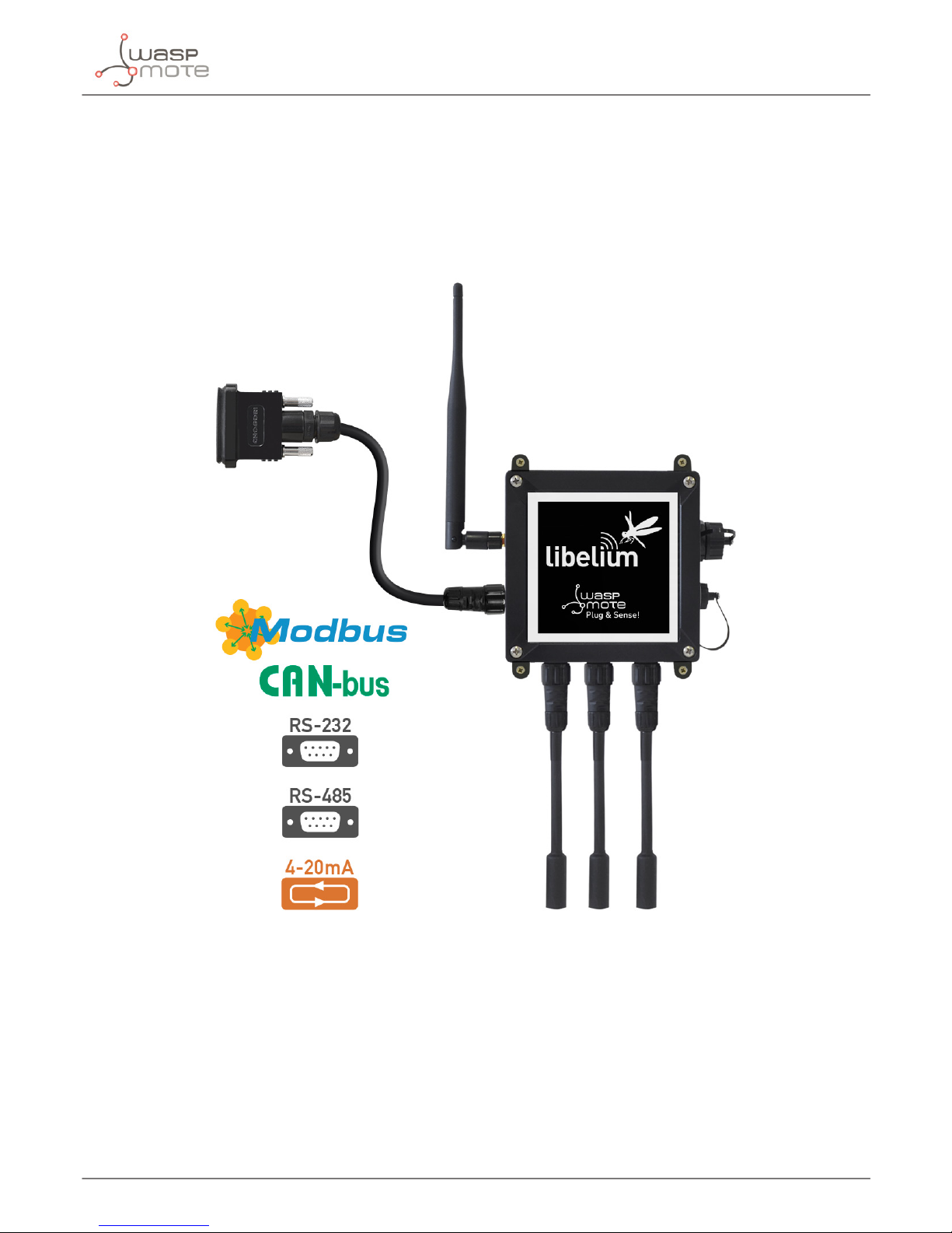
3.12. Industrial Protocols
Besides the main radio of Waspmote Plug & Sense!, it is possible to have an Industrial Protocol module as a
secondary communication option. This is oered as an accessory feature.
The available Industrial Protocols are RS-232, RS-485, Modbus (software layer over RS-232 or RS-485) and CAN Bus.
This optional feature is accessible through an additional, dedicated socket on the antenna side of the enclosure.
Figure: Industrial Protocols available on Plug & Sense!
Page 23
-23-
v7.3
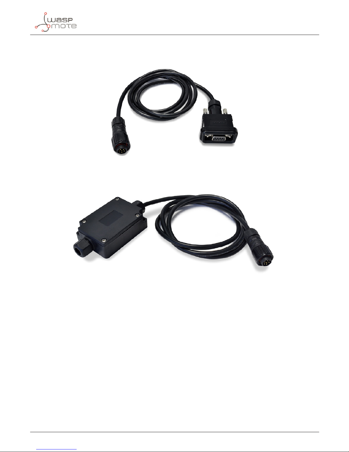
Waspmote Plug & Sense!
Finally, the user can choose between 2 probes to connect the desired Industrial Protocol: A standard DB9 connector
and a waterproof terminal block junction box. These options make the connections on industrial environments or
outdoor applications easier.
Figure: DB9 probe
Figure: Terminal box probe
Page 24
-24-
v7.3
Waspmote Plug & Sense!
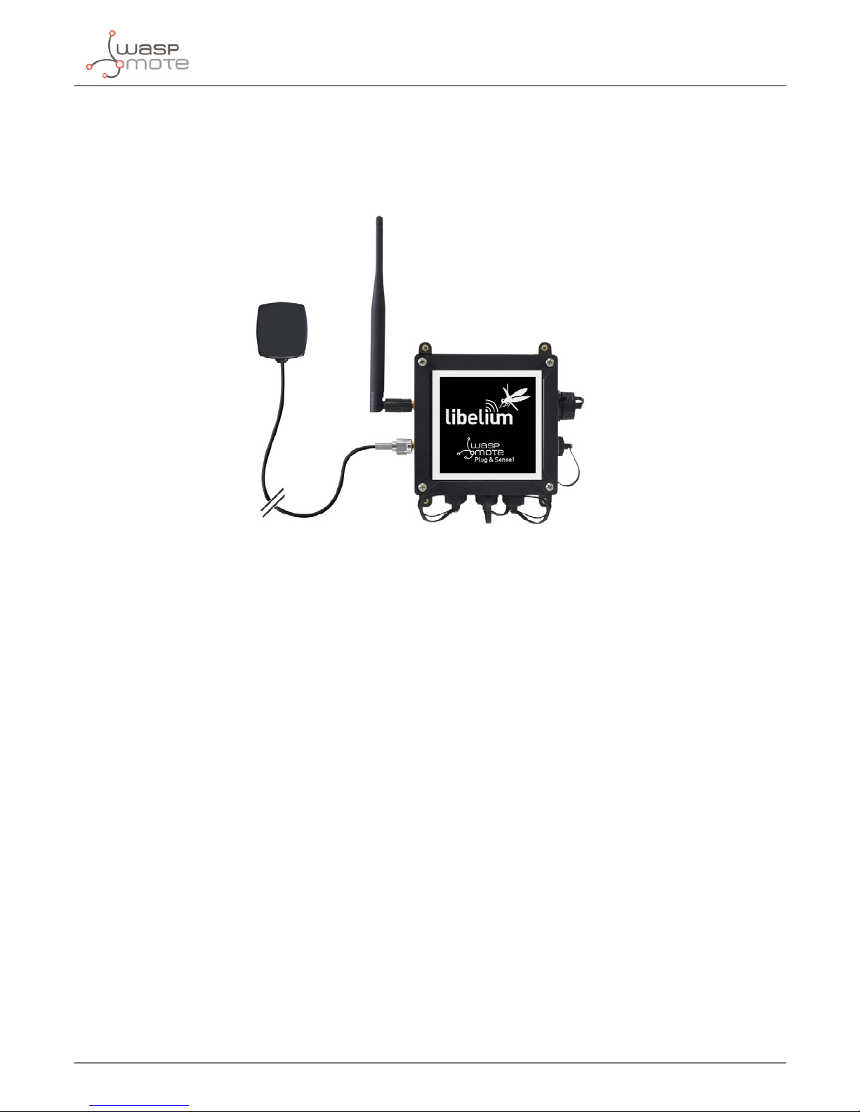
3.13. GPS
Any Plug & Sense! node can incorporate a GPS receiver in order to implement real-time asset tracking applications.
The user can also take advantage of this accessory to geolocate data on a map. An external, waterproof antenna
is provided; its long cable enables better installation for maximum satellite visibility.
Figure: Plug & Sense! node with GPS receiver
Chipset: JN3 (Telit)
Sensitivity:
• Acquisition: -147 dBm
• Navigation: -160 dBm
• Tracking: -163 dBm
Hot start time: <1 s
Cold start time: <35 s
Positional accuracy error < 2.5 m
Speed accuracy < 0.01 m/s
EGNOS, WAAS, GAGAN and MSAS capability
Antenna:
• Cable length: 2 m
• Connector: SMA
• Gain: 26 dBi (active)
Available information: latitude, longitude, altitude, speed, direction, date&time and ephemeris management
Page 25
-25-
v7.3
Waspmote Plug & Sense!
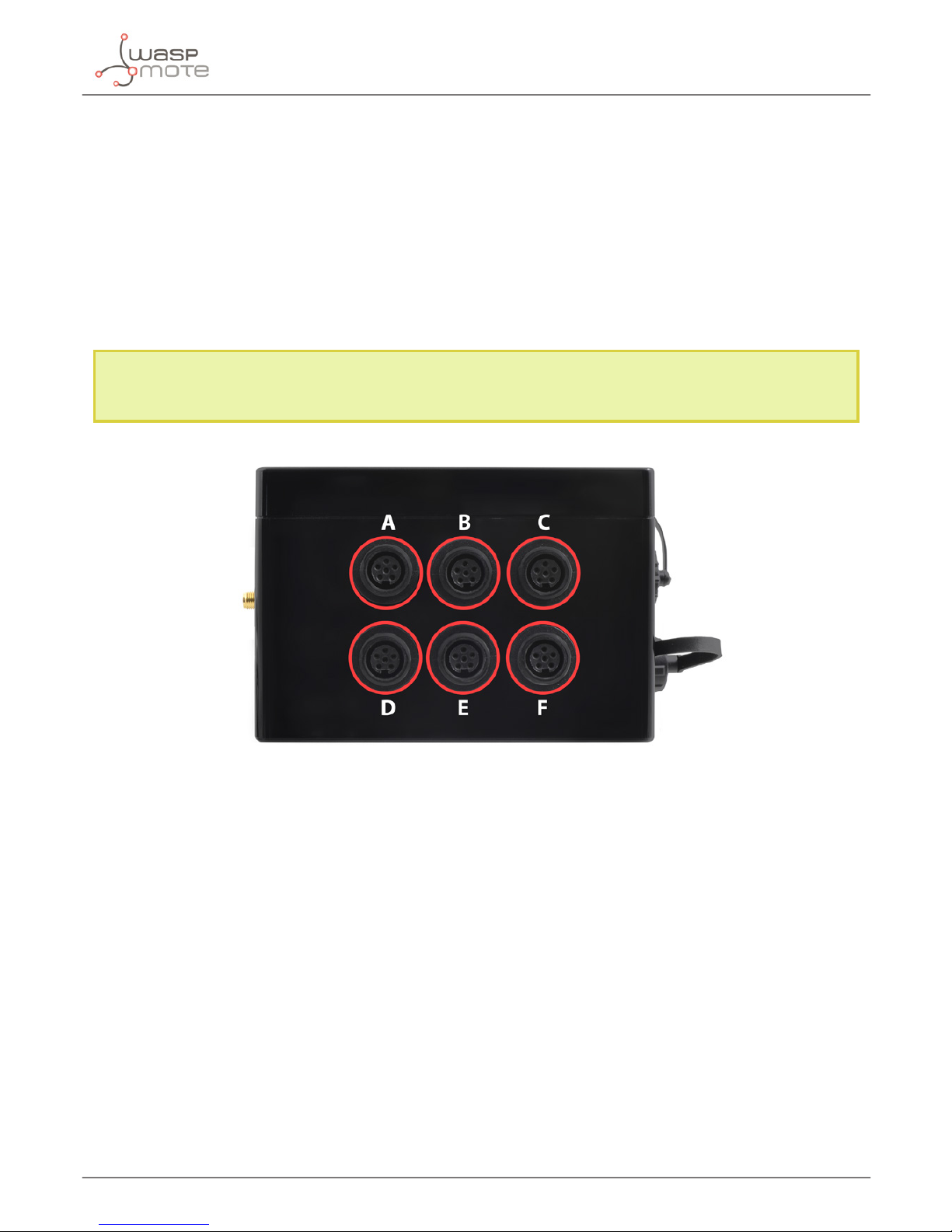
3.14. Models
There are some dened congurations of Waspmote Plug & Sense! depending on which sensors are going to be
used. Waspmote Plug & Sense! congurations allow to connect up to six sensor probes at the same time.
Each model takes a dierent conditioning circuit to enable the sensor integration. For this reason each model
allows to connect just its specic sensors.
This section describes each model conguration in detail, showing the sensors which can be used in each case
and how to connect them to Waspmote. In many cases, the sensor sockets accept the connection of more than
one sensor probe. See the compatibility table for each model conguration to choose the best probe combination
for the application.
It is very important to remark that each socket is designed only for one specic sensor, so they are not
interchangeable. Always be sure you connected probes in the right socket, otherwise they can be damaged.
Figure: Identication of sensor sockets
Page 26
-26-
v7.3
Waspmote Plug & Sense!
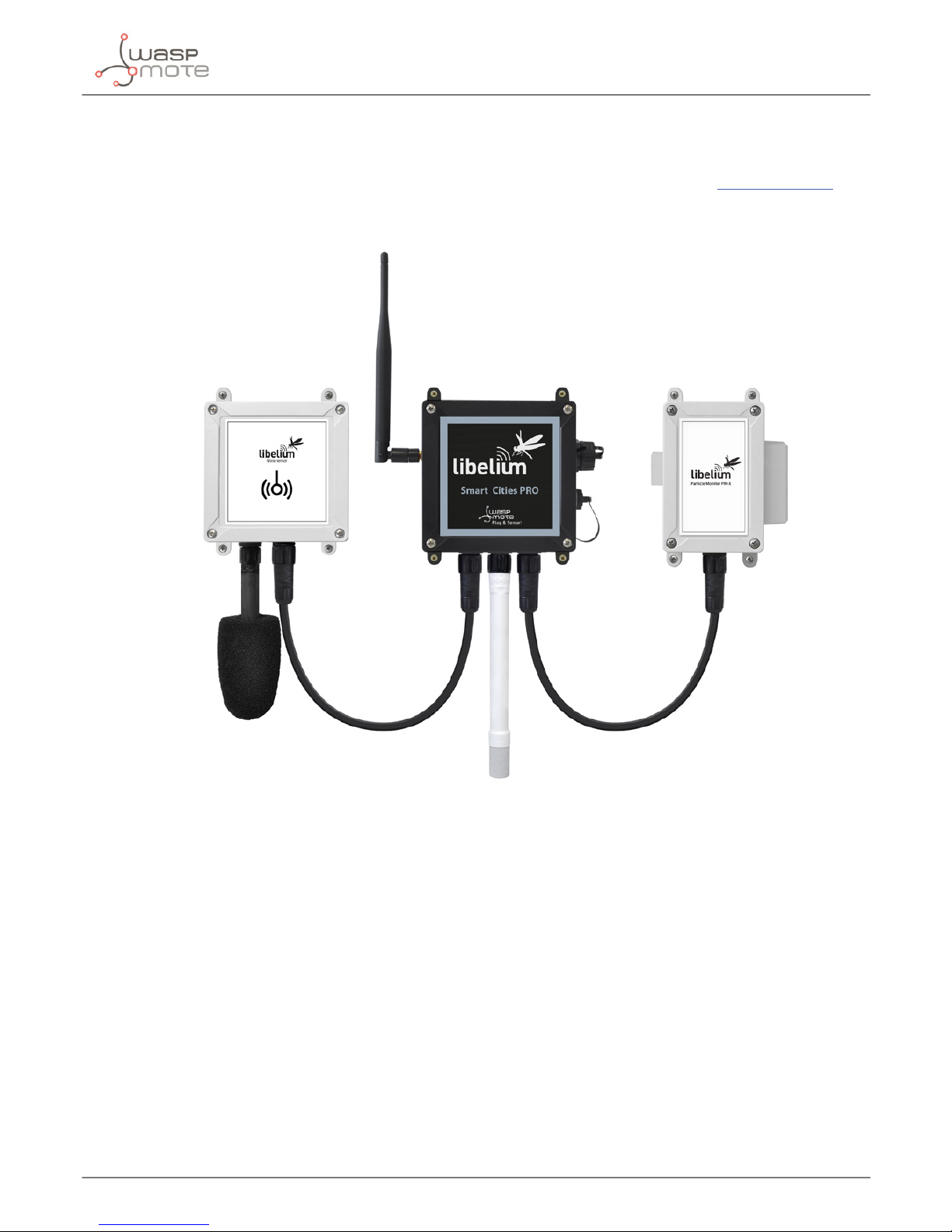
3.14.1. Smart Cities PRO
The main applications for this Waspmote Plug & Sense! model are noise maps (monitor in real time the acoustic
levels in the streets of a city), air quality, waste management, smart lighting, etc. Refer to Libelium website for
more information.
Figure: Smart Cities PRO Waspmote Plug & Sense! model
Page 27

-27-
v7.3
Waspmote Plug & Sense!
Sensor sockets are congured as shown in the gure below.
Sensor
Socket
Sensor probes allowed for each sensor socket
Parameter Reference
A
Noise level sensor NLS
Temperature + Humidity + Pressure 9370-P
Luminosity (Luxes accuracy) 9325-P
Ultrasound (distance measurement) 9246-P
B, C and F
Carbon Monoxide (CO) for high concentrations
[Calibrated]
9371-P
Carbon Monoxide (CO) for low concentrations
[Calibrated]
9371-LC-P
Carbon Dioxide (CO2) [Calibrated] 9372-P
Oxygen (O2) [Calibrated] 9373-P
Ozone (O3) [Calibrated] 9374-P
Nitric Oxide (NO) for low concentrations [Calibrated] 9375-LC-P
Nitric Dioxide (NO2) high accuracy [Calibrated] 9376-HA-P
Sulfur Dioxide (SO2) high accuracy [Calibrated] 9377-HA-P
Ammonia (NH3) for low concentrations [Calibrated] 9378-LC-P
Ammonia (NH3) for high concentrations [Calibrated] 9378-HC-P
Methane (CH4) and Combustible Gas [Calibrated] 9379-P
Hydrogen (H2) [Calibrated] 9380-P
Hydrogen Sulde (H2S) [Calibrated] 9381-P
Hydrogen Chloride (HCl) [Calibrated] 9382-P
Hydrogen Cyanide (HCN) [Calibrated] 9383-P
Phosphine (PH3) [Calibrated] 9384-P
Ethylene (ETO) [Calibrated] 9385-P
Chlorine (Cl2) [Calibrated] 9386-P
Temperature + Humidity + Pressure 9370-P
Luminosity (Luxes accuracy) 9325-P
Ultrasound (distance measurement) 9246-P
D Particle Matter (PM1 / PM2.5 / PM10) - Dust 9387-P
E
Temperature + Humidity + Pressure 9370-P
Luminosity (Luxes accuracy) 9325-P
Ultrasound (distance measurement) 9246-P
Figure: Sensor sockets configuration for Smart Cities PRO model
Note: For more technical information about each sensor probe go to the Development section in Libelium website.
Calibrated gas sensors are manufactured once the order has been placed to ensure maximum durability of the
calibration feature. The manufacturing process and delivery may take from 4 to 6 weeks. The lifetime of calibrated
gas sensors is 6 months working at maximum accuracy. We strongly encourage our customers to buy extra gas
sensors to replace the original ones after that time to ensure maximum accuracy and performance.
Page 28
-28-
v7.3
Hardware
4. Hardware
4.1. General description
The purpose of the Waspmote Smart Cities PRO board is to extend the monitoring functionalities from indoor
environments to outdoor locations, in order to perform IoT projects in Smart Cities and urban environments.
Most of the sensors available for Smart Cities PRO are available for the Gases PRO Sensor Board. Also, the Smart
Cities PRO board adds support for the Noise Level Sensor.
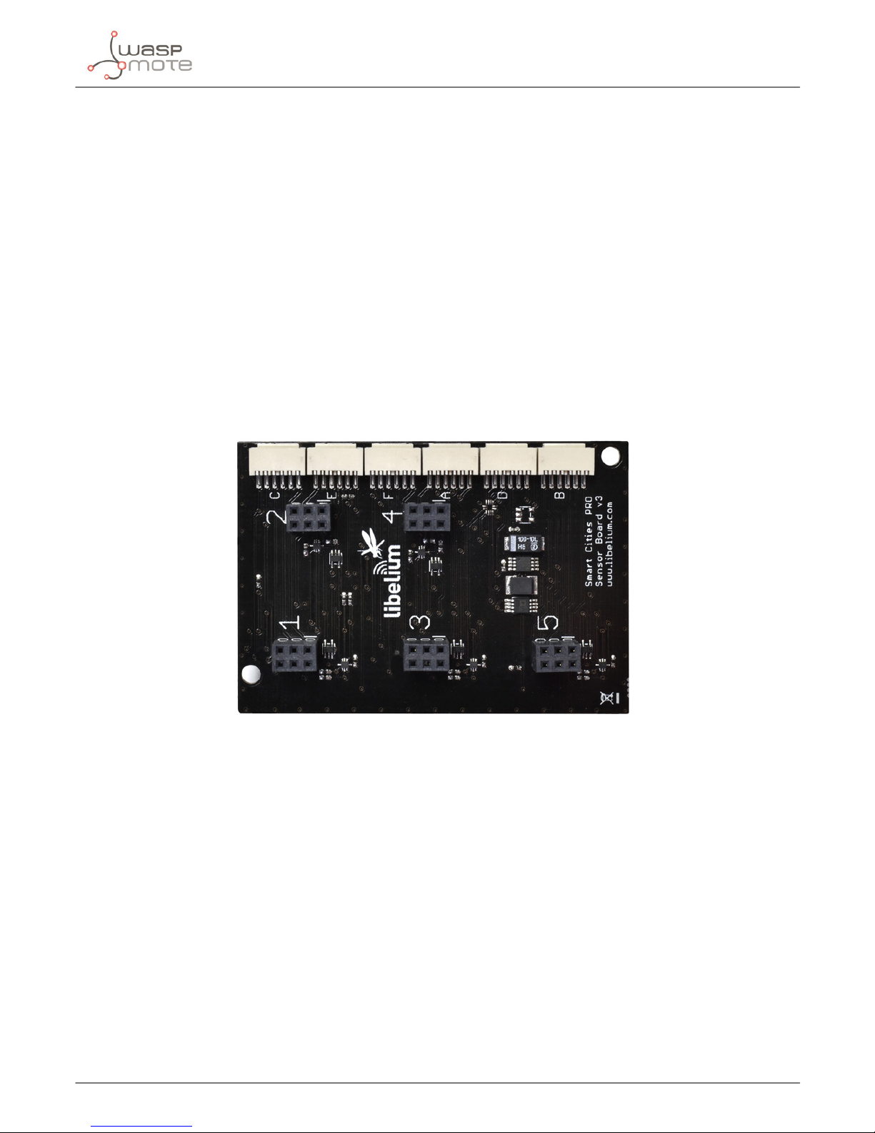
4.2. Specications
• Weight: 20 g
• Dimensions: 73.5 x 51 x 22 mm (without sensors)
• Temperature range: [-20 ºC, 65 ºC]
Figure: Top side of the Smart Cities PRO Sensor Board
4.3. Electrical characteristics
• Board power voltages: 3.3 V and 5 V
• Sensor power voltages: 3.3 V and 5 V
• Maximum admitted current (continuous): 200 mA
• Maximum admitted current (peak): 400 mA
Page 29

-29-
v7.3
Sensors
5. Sensors
Many of the sensors available for Smart Cities PRO are actually migrated from the Gases PRO sensor board,
where they were integrated initially. For a better understanding of the characteristics of sensors, its calibration
and performance, it is highly advised to read the Gases PRO Technical Guide, specially the chapters “Gases
PRO sensor board”, “Hardware” and “Sensors”.
5.1. Temperature, Humidity and Pressure Sensor
The BME280 is a digital temperature, humidity and atmospheric pressure sensor developed by Bosch Sensortec.
5.1.1. Specications
Electrical characteristics
Supply voltage: 3.3 V
Sleep current typical: 0.1 μA
Sleep current maximum: 0.3 μA
Temperature sensor
Operational range: -40 ~ +85 ºC
Full accuracy range: 0 ~ +65 ºC
Accuracy: ±1 ºC (range 0 ºC ~ +65 ºC)
Response time: 1.65 seconds (63% response from +30 to +125 °C).
Typical consumption: 1 μA measuring
Humidity sensor
Measurement range: 0 ~ 100% of relative humidity (for temperatures < 0 °C and > 60 °C see gure below)
Accuracy: < ±3% RH (at 25 ºC, range 20 ~ 80%)
Hysteresis: ±1% RH
Operating temperature: -40 ~ +85 ºC
Response time (63% of step 90% to 0% or 0% to 90%): 1 second
Typical consumption: 1.8 μA measuring
Maximum consumption: 2.8 μA measuring
Figure: Temperature, Humidity and Pressure Sensor
Page 30

-30-
v7.3
Sensors
Figure: Humidity sensor operating range
Pressure sensor
Measurement range: 30 ~ 110 kPa
Operational temperature range: -40 ~ +85 ºC
Full accuracy temperature range: 0 ~ +65 ºC
Absolute accuracy: ±0.1 kPa (0 ~ 65 ºC)
Typical consumption: 2.8 μA measuring
Maximum consumption: 4.2 μA measuring
5.1.2. Measurement process
The BME280 is as combined digital humidity, pressure and temperature sensor based on proven sensing principles.
The humidity sensor provides an extremely fast response time for fast context awareness applications and high
overall accuracy over a wide temperature range.
The pressure sensor is an absolute barometric pressure sensor with extremely high accuracy and resolution and
drastically lower noise.
The integrated temperature sensor has been optimized for lowest noise and highest resolution.
Its output is used for temperature compensation of the pressure and humidity sensors and can also be used for
estimation of the ambient temperature.
When the sensor is disabled, current consumption drops to 0.1 μA.
You can nd a complete example code for reading the BME280 sensor in the following link:
http://www.libelium.com/development/waspmote/examples/scp-v30-05-temperature-humidity-and-pressuresensor
Page 31

-31-
v7.3
Sensors
5.1.3. Socket
This sensor can be connected in sockets 1, 2, 3, 4 and 5 in Waspmote OEM and sockets A, B, C, E and F in Plug &
Sense!.
Figure: Temperature, Humidity and Pressure Sensors in sockets 1, 2, 3, 4 and 5
In the image above we can see highlighted the four pins of the terminal block where the sensor must be connected
to the board. The white dot on the luxes board, must match the mark of the Smart Cities PRO Sensor Board.
Please mind that each socket has 3 rows, but only 2 are used for that sensor, because it only has 2x2 pins. A bad
connection can cause malfunction or even hardware damage.
Page 32

-32-
v7.3
Sensors
5.2. Ultrasound sensor probe (MaxSonar® from MaxBotix™)
5.2.1. Specications
I2CXL-MaxSonar®-MB7040™
Operation frequency: 42 kHz
Maximum detection distance: 765 cm
Interface: Digital bus
Power supply: 3.3 V
Consumption (average): 2.1 mA
Consumption (peak): 50 mA
Usage: Indoors and outdoors (IP-67)
A 1.72” dia. 43.8 mm dia.
B 2.00” 50.7 mm
C 0.58” 14.4 mm
D 0.31” 7.9 mm
E 0.18” 4.6 mm
F 0.1” 2.54 mm
G 3/4” National Pipe Thread Straight
H 1.032” dia. 26.2 dia.
I 1.37” 34.8 mm
weight: 1.76 oz. ; 50 grams
Figure: Ultrasonic I2CXL-MaxSonar®-MB7040 sensor dimensions
In the gure below we can see a diagram of the detection range of the sensor developed using dierent detection
patterns (a 0.63 cm diameter dowel for diagram A, a 2.54 cm diameter dowel for diagram B, an 8.25cm diameter
rod for diagram C and a 28 cm wide board for diagram D):
Figure: Diagram of the sensor beam extracted from the data sheet of the XL-MaxSonar®-WRA1™ sensor from MaxBotix
Figure: Ultrasonic I2CXL-MaxSonar®-MB7040 from MaxBotix™
sensor
Page 33

-33-
v7.3
Sensors
I2CXL-MaxSonar®-MB1202™:
Figure: Ultrasonic I2CXL-MaxSonar®- MB1202 from MaxBotix™
Sensor
• Operation frequency: 42 kHz
• Maximum detection distance: 765 cm
• Consumption (average): 2 mA
• Consumption (peak): 50 mA
• Usage: Indoors only
A 0.785” 19.9 mm H 0.100” 2.54 mm
B 0.870” 22.1 mm J 0.645” 16.4 mm
C 0.100” 2.54 mm K 0.610” 15.5 mm
D 0.100” 2.54 mm L 0.735” 18.7 mm
E 0.670” 17.0 mm M 0.065” 1.7 mm
F 0.510” 12.6 mm N 0.038” dia. 1.0 mm
dia.
G 0.124” dia. 3.1 mm
dia.
weight: 4.3 grams
Figure: Ultrasonic I2CXL-MaxSonar®-MB1202 Sensor dimensions
In the gure below we can see a diagram of the detection range of the sensor developed using dierent detection
patterns (a 0.63 cm diameter dowel for diagram A, a 2.54 cm diameter dowel for diagram B, an 8.25 cm diameter
rod for diagram C and a 28 cm wide board for diagram D):
Figure: Diagram of the sensor beam extracted from the data sheet of the Ultrasonic I2CXL-MaxSonar®-MB1202 sensor from MaxBotix
Page 34

-34-
v7.3
Sensors
5.2.2. Measurement Process
The MaxSonar® sensors from MaxBotix can be connected through the digital bus interface.
In the next gure, we can see a drawing of two example applications for the ultrasonic sensors, such as liquid level
monitoring or presence detection.
Figure: Examples of application for the MaxSonar® sensors
The MB7040 sensor is endowed with an IP-67 casing, so it can be used in outdoors applications, such as liquid
level monitoring in storage tanks.
You can nd a complete example code for reading the distance in the following link:
www.libelium.com/development/waspmote/examples/scp-v30-06-ultrasound-sensor
5.2.3. Socket
These sensors can be connected in socket 1, 2, 3, 4 and 5 in Waspmote OEM and sockets A, B, C, E and F in Plug
& Sense!.
Figure: Images of the sockets for connecting the MaxSonar® Sensors
Page 35

-35-
v7.3
Sensors
5.3. Luminosity (Luxes accuracy) Sensor
5.3.1. Specications
Electrical characteristics
Dynamic range: 0.1 to 40000 lux
Spectral range: 300 ~ 1100 nm
Voltage range: 2.7 ~ 3.6 V
Supply current typical: 0.24 mA
Sleep current maximum: 0.3 μA
Operating temperature: -30 ~ 70 ºC
5.3.2. Measurement process
This is a light-to-digital converter that transforms light intensity into a digital signal output. This device combines
one broadband photo-diode (visible plus infrared) and one infrared-responding photo-diode on a single CMOS
integrated circuit capable of providing a near-photopic response over an eective 20-bit dynamic range (16-bit
resolution). Two integrating ADCs convert the photo-diode currents to a digital output that represents the irradiance
measured on each channel. This digital output in lux is derived using an empirical formula to approximate the
human eye response.
You can nd a complete example code for reading the luminosity in the following link:
www.libelium.com/development/waspmote/examples/scp-v30-07-luxes-sensor
5.3.3. Socket
This sensor can be connected in socket 1, 2, 3, 4 and 5 in Waspmote OEM and sockets A, B, C, E and F in Plug &
Sense!
Figure: Luxes sensors connected in sockets 1, 2, 3, 4 and 5
In the image above we can see highlighted the four pins of the terminal block where the sensor must be connected
to the board. The white dot on the luxes board, must match the mark of the Smart Cities PRO Sensor Board.
Please mind that each socket has 3 rows, but only 2 are used for that sensor, because it only has 2x2 pins. A bad
connection can cause malfunction or even hardware damage.
Figure: Image of the Luminosity Sensor
Page 36

-36-
v7.3
Sensors
5.4. Particle Matter (PM1 / PM2.5 / PM10) - Dust Sensor
5.4.1. Specications
Sensor: OPC-N2
Performance Characteristics
Laser classication: Class 1 as enclosed housing
Particle range (um): 0.38 to 17 spherical equivalent size (based on RI of 1.5)
Size categorization (standard): 16 software bins
Sampling interval (seconds): 1 to 10 histogram period
Total ow rate: 1.2 L/min
Sample ow rate: 220 mL/min
Max particle count rate: 10000 particles/second
Max Coincidence probability: 0.91% at 10 particles/L
0.24% at 500 particles/mL
Power Characteristics
Measurement mode (laser and fan on): 250 mA @ 5 Volts (typical)
Voltage Range: 4.8 to 5.2 V DC
Operation Conditions
Temperature Range: -10 ºC to 50 ºC
Operating Humidity: 0 to 99% RH non-condensing
This sensor has a high current consumption. It is very important to turn on the sensor to perform a measure and
then, turn it o to save battery. Also, it is advised to operate with a minimum battery level of 40%, just to avoid
voltage drops (due to high current peaks) which could lead to resets in the system.
Dust, dirt or pollen may be accumulated inside the dust sensor structure, especially when the sensor is close
to possible solid particle sources: parks, construction works, deserts. That is why it is highly recommended to
perform maintenance/cleaning tasks in order to have accurate measures. This maintenance/cleaning frequency
may vary depending on the environment conditions or amount of obstructing dust. In clean atmospheres or
with low particle concentrations, the maintenance/cleaning period will be longer than a place with a high particle
concentrations.
Important note: Do not handle the stickers seals of the enclosure (Warranty stickers). Their integrity is the proof that the
sensor enclosure has not been opened. If they have been handled, damaged or broken, the warranty is automatically
void.
DO NOT remove the external housing: this not only ensures the required airow, also protects the user from the
laser light. Removal of the casing may expose the user to Class 3B laser radiation. You must avoid exposure to
the laser beam. Do not use if the outer casing is damaged. Return to Libelium. Removal of the external housing
exposes the OPC circuitry which contains components that are sensitive to static discharge damage.
Note: The Particle Matter (PM1 / PM2.5 / PM10) – Dust Sensor is available only for the Plug & Sense! line (socket D).
Figure: Image of the Particle Matter sen-
sor, encapsulated
Page 37

-37-
v7.3
Sensors
5.4.2. Particle matter: the parameter
Particle matter is composed of small solid or liquid particles oating in the air. The origin of these particles can be
the industrial activity, exhaust fumes from diesel motors, building heating, pollen, etc. This tiny particles enter our
bodies when we breath. High concentrations of particle matter can be harmful for humans or animals, leading to
respiratory and coronary diseases, and even lung cancer. That is why this is a key parameter for the Air Quality
Index.
Some examples:
• Cat allergens: 0.1-5 μm
• Pollen: 10-100 μm
• Germs: 0.5-10 μm
• Oil smoke: 1-10 μm
• Cement dust: 5-100 μm
• Tobacco smoke: 0.01-1 μm
The smaller the particles are, the more dangerous, because they can penetrate more in our lungs. Many times,
particles are classied:
• PM1: Mass (in μg) of all particles smaller than 1 μm, in 1 m
3
• PM2.5: Mass (in μg) of all particles smaller than 2.5 μm, in 1 m
3
• PM10: Mass (in μg) of all particles smaller than 10 μm, in 1 m
3
Many countries and health organizations have studied the eect of the particle matter in humans, and they have
set maximum thresholds. As a reference, the maximum allowed concentrations are about 20 μm/m3 for PM2.5
and about 50 μm/m3 for PM10.
5.4.3. Measurement process
Like conventional optical particle counters, the OPC-N2 measures the light scattered by individual particles
carried in a sample air stream through a laser beam. These measurements are used to determine the particle size
(related to the intensity of light scattered via a calibration based on Mie scattering theory) and particle number
concentration. Particle mass loading- PM2.5 or PM10, are then calculated from the particle size spectra and
concentration data, assuming density and refractive index. To generate the air stream, the OPC-N2 uses only a
miniature low-power fan.
The OPC-N2 classies each particle size, at rates up to ~10,000 particle per second, adding the particle diameter
to one of 16 “bins” covering the size range from ~0.38 to 17 μm. The resulting particle size histograms can be
evaluated over user-dened sampling times from 1 to 10 seconds duration, the histogram data being transmitted
along with other diagnostic and environmental data (air temperature and air pressure). When the histogram is
read, the variables in the library are updated automatically. See the API section to know how to manage and read
this sensor.
You can nd a complete example code for reading the Particle Matter Sensor in the following link:
http://www.libelium.com/development/waspmote/examples/scp-v30-04-particle-matter-sensor
Page 38

-38-
v7.3
Sensors
5.5. Noise / Sound Level Sensor
5.5.1. Specications of the Sound Level Sensor probe
• Target parameter: LeqA
• Microphone sensitivity: 12.7 mV / Pa
• Range of the sensor: 50 dBA to 100 dBA
• Accuracy: +/-0.5dBA (1KHz)
• Frequency range: 20 Hz – 20 kHz
• Omni-directional microphone
• A-weighting measure
• Sound pressure level measurement (no weighting lter)
• FAST mode (125 ms) and SLOW mode (1 second), software congurable
5.5.2. Specications of the enclosure
• Material: polycarbonate
• Sealing: polyurethane
• Cover screws: stainless steel
• Ingress protection: IP65
• Impact resistance: IK08
• Rated insulation voltage AC: 690 V
• Rated insulation voltage DC: 1000 V
• Heavy metals-free
• Weatherproof: true - nach UL 746 C
• Ambient temperature (min.): -10 °C
• Ambient temperature (max.): 50 °C
• Approximated weight: 800 g
5.5.3. Sound pressure level measurement
The sound pressure level or acoustic pressure level is a measure of the eective pressure of a sound relative to
a reference value, normally referenced to pressure in air (20 µPa), which is considered as the threshold of the
human hearing. The expression of the sound pressure level is dened by:
Figure: Sound pressure level expression
Figure: Noise / Sound Level Sensor
Page 39

-39-
v7.3
Sensors
Where p is the root mean square sound pressure and p0 is the reference sound pressure (20 µPa). The next table
shows some examples of dierent sound pressure measurements:
Sound sources examples
Sound pressure level
(dB)
Sound pressure (Pa = N/
m2)
Sound intensity (W/m2)
Threshold of pain 130 63.2 10
Threshold of discomfort 120 20 1
Airport 110 6.3 0.01
Factory 100 2 0.001
Heavy trac 90 0.63 0.0001
Hair dryer 80 0.2 0.00001
Restaurant 70 0.063 0.000001
Conversation 60 0.02 0.0000001
Background noise 50 0.0063 0.00000001
Refrigerator 40 0.002 0.000000001
Library 30 0.00063 0.0000000001
Recording studio 20 0.0002 0.00000000001
Anechoic chamber 10 0.000063 0.000000000001
Threshold of hearing 0 0.00002 0.0000000000001
5.5.4. Equivalent continuous sound level
The sound pressure level parameter, explained in the previous section, is not much used in noise measurements.
Instead, an average value called Leq, is used. Equivalent Continuous Sound Level (Leq) is the average of the sound
pressure level during a period of time. This value is very used when the noise level is varying quickly. Below the
equation to calculate the Leq value in decibels.
The Leq is the most used parameter by most countries for measuring the exposure to noise levels and earing
damage risk. A better approximation to the human ear response is the LAeq (equivalent continuous A-weighted
sound pressure level). The A-weighting lter is described in the next section of this guide.
5.5.5. The A-weighting
The A-weighting is the most used curve of the family of curves dened by the IEC 61672 standard. It is very used
for measuring environmental and industrial noise, due to the fact that the curve follows the frequency sensitivity
of the human ear. Noise measurements made with the A-weighting scale are designated dBA. The A-weighting
also predicts quite well the damage risk of the ear. The next graph shows the response of the A-weighting across
the frequency range 10 Hz – 20 kHz.
Page 40

-40-
v7.3
Sensors
Figure: Graph of the A-weighting curve
5.5.6. International standard IEC 61672-1:2013
The new Noise / Sound Level Sensor has been designed following the specications of the IEC 61672 standard for
sound meters. Specically with an accuracy of ±2 dBA similar to the Class 2 type devices. The value given is the
LeqA (Equivalent continuous sound level, with A weighting) that allows to calculate the average sound pressure
level during a period of time. Leq is often described as the average noise level during a noise measurement and it
is the magnitude used for many regulations of noise control at work places and the street.
5.5.7. Measurement process
As mentioned previously, the Sound Level Sensor can only be used in combination with a Plug & Sense! Smart
Cities PRO device. Once the sensor is connected following the previous steps, the Waspmote Plug & Sense! unit
must be programmed for reading the sound pressure values.
You can nd a complete example code for reading the temperature sensor in the following link:
http://www.libelium.com/development/waspmote/examples/scp-v30-08-noise-level-sensorg
5.5.8. Calibration Tests
In order to ensure the high quality of the Noise / Sound Level Sensor, each device is veried in an independent
test laboratory.
Tests are performed inside an isolated anechoic chamber. The sound sensor probes are exposed to 5 dierent
levels of white noise, created by a specialized sound generator and a cutting-edge, omni-directional speaker: 55,
65, 75, 85 and 95 dBA. The exact level is conrmed by the technician with a certied IEC 61672 soundmeter, placed
at the same distance from the sound source than the 16 sensors. For each noise level, the output of each one of
the 16 sensors is captured by a software system.
Tested equipment
Noise source
Page 41

-41-
v7.3
Sensors
After those tests, an ocial test report is issued by the laboratory for every Noise / Sound Level Sensor, so the
customer can verify the accuracy in dBA at dierent frequencies for each sound level probe. See below an example
of this document.
Figure: Example of test report obtained in the laboratory
Page 42

-42-
v7.3
Sensors
Page 43

-43-
v7.3
Sensors
5.5.9. Mounting the Noise / Sound Level Sensor and supplying power
Important: The Noise Level Sensor has been designed to be used with the Waspmote Plug & Sense! Smart Cities
PRO and it cannot be used independently. This sensor cannot be used on a Waspmote OEM with a Smart Cities PRO
board, for example.
The Sound Level Sensor consists of the next items shown in the gure below:
1
2
5
3
4
Figure: Noise Level Sensor items: 1 Noise Level Sensor. 2 Noise Level Sensor enclosure. 3 Data cable. 4 Power supply cable. 5 Protection
cover
Page 44

-44-
v7.3
Sensors
The images below show the dierent sockets of the Noise Level Sensor.
Microphone Data Cable
Figure: Identication of the connectors
Power Supply
Figure: Power supply connector
Figure: Noise Level Sensor probe
Page 45

-45-
v7.3
Sensors
To connect the Sound Level Sensor probe to the enclosure, It should be taken into account that the sensor probe
connector has only one matching position. The user should align the sensor probe connector looking at the little
notch of the connector (see image below). Notice that the sensor connector is male-type and the enclosure sensor
connector is female-type.
Figure: Detail of the sensor probe connector
Besides, there is a locking nut which should be screwed till the connector is completely xed to the enclosure.
Figure: Connecting the sensor probe to the enclosure
Page 46

-46-
v7.3
Sensors
After connecting the sensor, connect the the power supply cable to the USB connector, as shown in the picture
below and the Noise Level Sensor will power up. Then, connect one end of data cable to the Sound Level Sensor
and the other one to the associated Plug & Sense! Smart Cities PRO device.
Data cable
Power supply
cable
Figure: Connecting the data cable and the power supply cable to the Noise Level Sensor
Figure: Connecting the data cable to the associated Plug & Sense! Smart Cities device
Page 47

-47-
v7.3
Sensors
Finally, the Noise Level Sensor can be installed outdoors in a streetlight or directly on a wall. The protection cover
should be placed like the pictures below, to protect the Sound Level Sensor probe from the rain.
Figure: Installing the Noise Level Sensor on a wall
Notice that the power supply cable has a waterproof end, suitable for outdoor applications. But, on the other side,
it has a non-waterproof end thought to be connected to a USB charger (AC/DC, 5 V output). Bear in mind that this
end is not waterproof so it cannot be used outdoors. Please protect it accordingly.
A typical application is to power a node placed on the facade of a building; the power supply cables go indoors
through a nearby window and the USB ends remain indoors, connected to a wall adapter. Many lampposts also
have a 220 V output inside.
Figure: Typical installation of the Noise Level Sensor
Page 48

-48-
v7.3
Sensors
5.6. Carbon Monoxide (CO) Gas Sensor for high concentrations [Calibrated]
5.6.1. Specications
Gas: CO
Sensor: 4-CO-500
Performance Characteristics
Nominal Range: 0 to 500 ppm
Maximum Overload: 2000 ppm
Long Term Output Drift: < 2% signal/month
Response Time (T90): ≤ 30 seconds
Sensitivity: 70 ± 15 nA/ppm
Accuracy: as good as ±1 ppm* (ideal conditions)
Operation Conditions
Temperature Range: -20 ºC to 50 ºC
Operating Humidity: 15 to 90% RH non-condensing
Pressure Range: 90 to 110 kPa
Storage Temperature: 0 ºC to 20 ºC
Expected Operating Life: 5 years in air
Sockets for Waspmote OEM:
• SOCKET_1
• SOCKET_3
• SOCKET_5
Sockets for Plug & Sense!:
• SOCKET_B
• SOCKET_C
• SOCKET_F
Average consumption: less than 1 mA
* Accuracy values are only given for the optimum case. See the “Calibration” chapter in the Gases PRO Technical Guide
for more detail.
The electrochemical sensors must be always powered on in order to get optimum measurements. This implies
a power consumption, however it improves the performance of the sensor. This should also be applied when
entering sleep modes so the sensor is not powered o selecting the proper sleep option.
Calibrated gas sensors are manufactured once the order has been placed to ensure maximum durability of the
calibration feature. The manufacturing process and delivery may take from 4 to 6 weeks. The lifetime of calibrated
gas sensors is 6 months working at maximum accuracy. We strongly encourage our customers to buy extra gas
sensors to replace the original ones after that time to ensure maximum accuracy and performance.
Figure: Image of the Carbon Monoxide
Sensor for high concentrations mounted on its AFE module
Page 49

-49-
v7.3
Sensors
5.6.2. Cross-sensitivity data
Gas Formula
Concentration
(ppm)
Output Signal
(ppm CO
equivalent)
Hydrogen Sulde H2S 24 0
Sulfur Dioxide SO
2
5 0
Cholrine Cl
2
10 0-1
Nitric Oxide O
2
25 0
Nitric Dioxide NO
2
5 0
Hydrogen H
2
100 40
Ethylene C2H
4
100 16
Figure: Cross-sensitivity data for the CO Sensor for high concentrations
You can nd a complete example code for reading the CO Sensor for high concentrations in the following link:
www.libelium.com/development/waspmote/examples/scp-v30-01-electrochemical-gas-sensors
Page 50

-50-
v7.3
Sensors
5.7. Carbon Monoxide (CO) Gas Sensor for low concentrations [Calibrated]
5.7.1. Specications
Gas: CO
Sensor: CO-A4
Performance Characteristics
Nominal Range: 0 to 25 ppm
Maximum Overload: 2000 ppm
Long Term Sensitivity Drift: < 10% change/year in lab air, monthly test
Long Term zero Drift: < ±100 ppb equivalent change/year in lab air
Response Time (T90): ≤ 20 seconds
Sensitivity: 220 to 375 nA/ppm
Accuracy: as good as ±0.1 ppm* (ideal conditions)
H2S lter capacity: 250000 ppm·hrs
Operation Conditions
Temperature Range: -30 ºC to 50 ºC
Operating Humidity: 15 to 90% RH non-condensing
Pressure Range: 80 to 120 kPa
Storage Temperature: 0 ºC to 20 ºC
Expected Operating Life: 3 years in air
Sockets for Waspmote OEM:
• SOCKET_1
• SOCKET_3
• SOCKET_5
Sockets for Plug & Sense!:
• SOCKET_B
• SOCKET_C
• SOCKET_F
Average consumption: less than 1 mA
* Accuracy values are only given for the optimum case. See the “Calibration” chapter in the Gases PRO Technical Guide
for more detail.
The electrochemical sensors must be always powered on in order to get optimum measurements. This implies
a power consumption, however it improves the performance of the sensor. This should also be applied when
entering sleep modes so the sensor is not powered o selecting the proper sleep option.
Calibrated gas sensors are manufactured once the order has been placed to ensure maximum durability of the
calibration feature. The manufacturing process and delivery may take from 4 to 6 weeks. The lifetime of calibrated
gas sensors is 6 months working at maximum accuracy. We strongly encourage our customers to buy extra gas
sensors to replace the original ones after that time to ensure maximum accuracy and performance.
Figure: Image of the Carbon Monoxide
Sensor for low concentrations mounted
on its AFE module
Page 51

-51-
v7.3
Sensors
5.7.2. Cross-sensitivity data
Gas Formula
Concentration
(ppm)
Output signal
(ppm CO
equivalent)
Hydrogen Sulde H2S 5 < 0.1
Nitric Dioxide NO
2
5 < -2
Chlorine Cl
2
5 < 0.1
Nitric Oxide NO 5 < -2
Sulfur Dioxide SO
2
5 < 0.1
Hydrogen H
2
100 < 10
Ethylene C2H
4
100 < 0.5
Ammonia NH
3
20 < 0.1
Figure: Cross-sensitivity data for the CO Sensor for low concentrations
You can nd a complete example code for reading the CO Sensor for low concentrations in the following link:
www.libelium.com/development/waspmote/examples/scp-v30-01-electrochemical-gas-sensors
Page 52

-52-
v7.3
Sensors
5.8. Carbon Dioxide (CO2) Gas Sensor [Calibrated]
5.8.1. Specications
Gas: CO
2
Sensor: NE20-CO2P-NCVSP
Performance Characteristics
Nominal Range: 0 to 5000 ppm
Long Term Output Drift: < ± 250 ppm/year
Warm up time: 60 seconds @ 25 ºC
At least 30 min for full specication @ 25 °C
Response Time (T90): ≤ 60 seconds
Resolution: 25 ppm
Accuracy: as good as ±50 ppm*, from 0 to 2500 ppm range (ideal conditions)
as good as ±200 ppm*, from 2500 to 5000 ppm range (ideal conditions)
Operation Conditions
Temperature Range: -40 ºC to 60 ºC
Operating Humidity: 0 to 95%RH non-condensing
Storage Temperature: -40 ºC to 85 ºC
MTBF: ≥ 5 years
Sockets for Waspmote OEM:
• SOCKET_1
Sockets for Plug & Sense!:
• SOCKET_B
• SOCKET_C
• SOCKET_F
Average consumption: 80 mA
Note: The CO2 Sensor and the Methane (CH4) and Combustible Gas Sensor have high power requirements and
cannot work together in the same Smart Cities PRO Sensor Board. The user must choose one or the other, but not
both.
* Accuracy values are only given for the optimum case. See the “Calibration” chapter in the Gases PRO Technical Guide
for more detail.
Calibrated gas sensors are manufactured once the order has been placed to ensure maximum durability of the
calibration feature. The manufacturing process and delivery may take from 4 to 6 weeks. The lifetime of calibrated
gas sensors is 6 months working at maximum accuracy. We strongly encourage our customers to buy extra gas
sensors to replace the original ones after that time to ensure maximum accuracy and performance.
You can nd a complete example code for reading the CO2 Sensor in the following link:
http://www.libelium.com/development/waspmote/examples/scp-v30-02-ndir-gas-sensors
Figure: Image of the Carbon Dioxide Sensor mounted on its AFE module
Page 53

-53-
v7.3
Sensors
5.9. Molecular Oxygen (O2) Gas Sensor [Calibrated]
5.9.1. Specications
Gas: O
2
Sensor: 4-OL
Performance Characteristics
Nominal Range: 0 to 30 Vol.%
Maximum Overload: 90 Vol.%
Long Term Output Drift: < 2% signal/3 months
Response Time (T90): ≤ 30 seconds
Sensitivity: 1.66 ± 0.238 nA/ppm
Accuracy: as good as ± 0.1 % (ideal conditions)
Operation Conditions
Temperature Range: -20 ºC to 50 ºC
Operating Humidity: 5 to 90%RH non-condensing
Pressure Range: 90 to 110 kPa
Storage Temperature: 0 ºC to 20 ºC
Expected Operating Life: 2 years in air
Sockets for Waspmote OEM:
• SOCKET_1
• SOCKET_3
• SOCKET_5
Sockets for Plug & Sense!:
• SOCKET_B
• SOCKET_C
• SOCKET_F
Average consumption: less than 1 mA
* Accuracy values are only given for the optimum case. See the “Calibration” chapter in the Gases PRO Technical Guide
for more detail.
The electrochemical sensors must be always powered on in order to get optimum measurements. This implies
a power consumption, however it improves the performance of the sensor. This should also be applied when
entering sleep modes so the sensor is not powered o selecting the proper sleep option.
Calibrated gas sensors are manufactured once the order has been placed to ensure maximum durability of the
calibration feature. The manufacturing process and delivery may take from 4 to 6 weeks. The lifetime of calibrated
gas sensors is 6 months working at maximum accuracy. We strongly encourage our customers to buy extra gas
sensors to replace the original ones after that time to ensure maximum accuracy and performance.
You can nd a complete example code for reading the O2 Sensor in the following link:
www.libelium.com/development/waspmote/examples/scp-v30-01-electrochemical-gas-sensors
Figure: Image of the Molecular Oxygen
Sensor mounted on its AFE module
Page 54

-54-
v7.3
Sensors
5.10. Ozone (O3) Gas Sensor [Calibrated]
5.10.1. Specications
Gas: O
3
Sensor: OX-A431
Performance Characteristics
Nominal Range: 0 to 18 ppm
Maximum Overload: 50 ppm
Long Term sensitivity Drift: -20 to -40% change/year
Response Time (T90): ≤ 45 seconds
Sensitivity: -200 to -550 nA/ppm
Accuracy: as good as ±0.2 ppm* (ideal conditions)
High cross-sensitivity with NO2 gas. Correction could be necessary in ambients with NO2.
Operation Conditions
Temperature Range: -30 ºC to 40 ºC
Operating Humidity: 15 to 85 %RH non-condensing
Pressure Range: 80 to 120 kPa
Storage Temperature: 3 ºC to 20 ºC
Expected Operating Life: > 24 months in air
Sockets for Waspmote OEM:
• SOCKET_1
• SOCKET_3
• SOCKET_5
Sockets for Plug & Sense!:
• SOCKET_B
• SOCKET_C
• SOCKET_F
Average consumption: less than 1 mA
* Accuracy values are only given for the optimum case. See the “Calibration” chapter in the Gases PRO Technical Guide
for more detail.
The electrochemical sensors must be always powered on in order to get optimum measurements. This implies
a power consumption, however it improves the performance of the sensor. This should also be applied when
entering sleep modes so the sensor is not powered o selecting the proper sleep option.
Calibrated gas sensors are manufactured once the order has been placed to ensure maximum durability of the
calibration feature. The manufacturing process and delivery may take from 4 to 6 weeks. The lifetime of calibrated
gas sensors is 6 months working at maximum accuracy. We strongly encourage our customers to buy extra gas
sensors to replace the original ones after that time to ensure maximum accuracy and performance.
Figure: Image of the Ozone Sensor mounted
on its AFE module
Page 55

-55-
v7.3
Sensors
5.10.2. Cross-sensitivity data
Gas Formula
Concentration
(ppm)
Output Signal
(ppm CO
equivalent)
Hydrogen Sulde H2S 5 < 100
Nitric Dioxide NO
2
5 70 to 120
Chlorine Cl
2
5 < 30
Nitric Oxide NO 5 < 3
Sulfur Dioxide SO
2
5 < -6
Carbon Monoxide CO 5 < 0.1
Hydrogen H
2
100 <0.1
Ethylene C2H
4
100 < 0.1
Ammonia NH
3
20 <0.1
Carbon Dioxide CO
2
50000 0.1
Halothane Halothane 100 < 0.1
Figure: Cross-sensitivity data for the O3 Sensor
This sensor has a very high cross-sensitivity with NO2 gas. So, the output in ambients with NO2 will be a mix of
O3 and NO2. A simple way to correct this eect is to subtract NO2 concentration from O3 concentration with an NO2
gas sensor. The measure from the NO2 sensor must be accurate in order to subtract the right value. See the related
section in the “Board conguration and programming” chapter to use the right function.
You can nd a complete example code for reading the O3 Sensor in the following link:
www.libelium.com/development/waspmote/examples/scp-v30-01-electrochemical-gas-sensors
Page 56

-56-
v7.3
Sensors
5.11. Nitric Oxide (NO) Gas Sensor for low concentrations
[Calibrated]
5.11.1. Specications
Gas: NO
Sensor: NO-A4
Performance Characteristics
Nominal Range: 0 to 18 ppm
Maximum Overload: 50 ppm
Long Term Sensitivity Drift: < 20% change/year in lab air, monthly test
Long Term zero Drift: 0 to 50 ppb equivalent change/year in lab air
Response Time (T90): ≤ 25 seconds
Sensitivity: 350 to 550 nA/ppm
Accuracy: as good as ±0.2 ppm* (ideal conditions)
Operation Conditions
Temperature Range: -30 ºC to 50 ºC
Operating Humidity: 15 to 85% RH non-condensing
Pressure Range: 80 to 120 kPa
Storage Temperature: 0 ºC to 20 ºC
Expected Operating Life: 2 years in air
Sockets for Waspmote OEM:
• SOCKET_1
• SOCKET_3
• SOCKET_5
Sockets for Plug & Sense!:
• SOCKET_B
• SOCKET_C
• SOCKET_F
Average consumption: less than 1 mA
* Accuracy values are only given for the optimum case. See the “Calibration” chapter in the Gases PRO Technical Guide
for more detail.
The electrochemical sensors must be always powered on in order to get optimum measurements. This implies
a power consumption, however it improves the performance of the sensor. This should also be applied when
entering sleep modes so the sensor is not powered o selecting the proper sleep option.
Calibrated gas sensors are manufactured once the order has been placed to ensure maximum durability of the
calibration feature. The manufacturing process and delivery may take from 4 to 6 weeks. The lifetime of calibrated
gas sensors is 6 months working at maximum accuracy. We strongly encourage our customers to buy extra gas
sensors to replace the original ones after that time to ensure maximum accuracy and performance.
Figure: Image of the Nitric Oxide Sensor
for low concentrations mounted on its
AFE module
Page 57

-57-
v7.3
Sensors
5.11.2. Cross-sensitivity data
Gas Formula
Concentration
(ppm)
Output Signal
(ppm NO
equivalent)
Carbon Monoxide CO 300 0
Sulfur Dioxide SO
2
5 0
Nitric Dioxide NO
2
5 1.5
Hydrogen Sulde H2S 15 -1.5
Figure: Cross-sensitivity data for the NO Sensor for low concentrations
You can nd a complete example code for reading the NO Sensor for low concentrations in the following link:
www.libelium.com/development/waspmote/examples/scp-v30-01-electrochemical-gas-sensors
Page 58

-58-
v7.3
Sensors
5.12. Nitric Dioxide (NO2) high accuracy Gas Sensor
[Calibrated]
5.12.1. Specications
Gas: NO
2
Sensor: NO2-A43F
Performance Characteristics
Nominal Range: 0 to 20 ppm
Maximum Overload: 50 ppm
Long Term Sensitivity Drift: < -20 to -40% change/year in lab air, monthly test
Long Term zero Drift: < 20 ppb equivalent change/year in lab air
Response Time (T90): ≤ 60 seconds
Sensitivity: -175 to -450 nA/ppm
Accuracy: as good as ±0.1 ppm* (ideal conditions)
O3 lter capacity @ 2 ppm: > 500 ppm·hrs
Operation Conditions
Temperature Range: -30 ºC to 40 ºC
Operating Humidity: 15 to 85% RH non-condensing
Pressure Range: 80 to 120 kPa
Storage Temperature: 0 ºC to 20 ºC
Expected Operating Life: 2 years in air
Sockets for Waspmote OEM:
• SOCKET_1
• SOCKET_3
• SOCKET_5
Sockets for Plug & Sense!:
• SOCKET_B
• SOCKET_C
• SOCKET_F
Average consumption: less than 1 mA
* Accuracy values are only given for the optimum case. See the “Calibration” chapter in the Gases PRO Technical Guide
for more detail.
The electrochemical sensors must be always powered on in order to get optimum measurements. This implies
a power consumption, however it improves the performance of the sensor. This should also be applied when
entering sleep modes so the sensor is not powered o selecting the proper sleep option.
Calibrated gas sensors are manufactured once the order has been placed to ensure maximum durability of the
calibration feature. The manufacturing process and delivery may take from 4 to 6 weeks. The lifetime of calibrated
gas sensors is 6 months working at maximum accuracy. We strongly encourage our customers to buy extra gas
sensors to replace the original ones after that time to ensure maximum accuracy and performance.
Figure: Image of the high accuracy Nitric
Dioxide Sensor mounted on its AFE module
Page 59

-59-
v7.3
Sensors
5.12.2. Cross-sensitivity data
Gas Formula
Concentration
(ppm)
Output Signal
(ppm NO2
equivalent)
Hydrogen Sulde H2S 5 < -80
Nitric Oxide NO 5 < 5
Chlorine Cl
2
5 < 75
Sulfur Dioxide SO
2
5 < -5
Carbon Monoxide CO 5 < -5
Ethylene C2H
4
100 < 1
Ammonia NH
3
20 < 0.2
Hydrogen H
2
100 < 0.1
Carbon Dioxide CO
2
5% vol 0.1
Halothane 100 nd
Figure: Cross-sensitivity data for the high accuracy NO2 Sensor
You can nd a complete example code for reading the high accuracy NO2 Sensor in the following link:
www.libelium.com/development/waspmote/examples/scp-v30-01-electrochemical-gas-sensors
Page 60

-60-
v7.3
Sensors
5.13. Sulfur Dioxide (SO2) high accuracy Gas Sensor [Calibrated]
5.13.1. Specications
Gas: SO
2
Sensor: SO2-A4
Performance Characteristics
Nominal Range: 0 to 20 ppm
Maximum Overload: 100 ppm
Long Term Sensitivity Drift: < ±15% change/year in lab air, monthly test
Long Term zero Drift: <±20 ppb equivalent change/year in lab air
Response Time (T90): ≤ 20 seconds
Sensitivity: 320 to 480 nA/ppm
Accuracy: as good as ±0.1 ppm* (ideal conditions)
Operation Conditions
Temperature Range: -30 ºC to 50 ºC
Operating Humidity: 15 to 90% RH non-condensing
Pressure Range: 80 to 120 kPa
Storage Temperature: 0 ºC to 20 ºC
Expected Operating Life: 2 years in air
Sockets for Waspmote OEM:
• SOCKET_1
• SOCKET_3
• SOCKET_5
Sockets for Plug & Sense!:
• SOCKET_B
• SOCKET_C
• SOCKET_F
Average consumption: less than 1 mA
* Accuracy values are only given for the optimum case. See the “Calibration” chapter in the Gases PRO Technical Guide
for more detail.
The electrochemical sensors must be always powered on in order to get optimum measurements. This implies
a power consumption, however it improves the performance of the sensor. This should also be applied when
entering sleep modes so the sensor is not powered o selecting the proper sleep option.
Calibrated gas sensors are manufactured once the order has been placed to ensure maximum durability of the
calibration feature. The manufacturing process and delivery may take from 4 to 6 weeks. The lifetime of calibrated
gas sensors is 6 months working at maximum accuracy. We strongly encourage our customers to buy extra gas
sensors to replace the original ones after that time to ensure maximum accuracy and performance.
Figure: Image of the high accuracy
Sulfur Dioxide Sensor mounted on its
AFE module
Page 61

-61-
v7.3
Sensors
5.13.2. Cross-sensitivity data
Gas Formula
Concentration
(ppm)
Output Signal
(ppm SO2
equivalent)
Hydrogen Sulde H2S 5 < 40
Nitric Oxide NO 5 < -160
Chlorine Cl
2
5 < -70
Sulfur Dioxide SO
2
5 < -1.5
Carbon Monoxide CO 5 < 2
Hydrogen H
2
100 < 1
Ethylene C2H
4
100 < 1
Ammonia NH
3
20 < 0.1
Carbon Dioxide CO
2
5% vol. < 0.1
Figure: Cross-sensitivity data for the high accuracy SO2 Sensor
You can nd a complete example code for reading the high accuracy SO2 Sensor in the following link:
www.libelium.com/development/waspmote/examples/scp-v30-01-electrochemical-gas-sensors
Page 62

-62-
v7.3
Sensors
5.14. Ammonia (NH3) Gas Sensor for low concentrations
[Calibrated]
5.14.1. Specications
Gas: NH
3
Sensor: 4-NH3-100
Performance Characteristics
Nominal Range: 0 to 100 ppm
Long Term Output Drift: < 2% signal/month
Response Time (T90): ≤ 90 seconds
Sensitivity: 135 ± 35 nA/ppm
Accuracy: as good as ±0.5 ppm* (ideal conditions)
Operation Conditions
Temperature Range: -20 ºC to 50 ºC
Operating Humidity: 15 to 90%RH non-condensing
Pressure Range: 90 to 110 kPa
Storage Temperature: 0 ºC to 20 ºC
Expected Operating Life: ≥1 year in air
Sockets for Waspmote OEM:
• SOCKET_1
• SOCKET_3
• SOCKET_5
Sockets for Plug & Sense!:
• SOCKET_B
• SOCKET_C
• SOCKET_F
Average consumption: less than 1 mA
* Accuracy values are only given for the optimum case. See the “Calibration” chapter in the Gases PRO Technical Guide
for more detail.
The electrochemical sensors must be always powered on in order to get optimum measurements. This implies
a power consumption, however it improves the performance of the sensor. This should also be applied when
entering sleep modes so the sensor is not powered o selecting the proper sleep option.
Calibrated gas sensors are manufactured once the order has been placed to ensure maximum durability of the
calibration feature. The manufacturing process and delivery may take from 4 to 6 weeks. The lifetime of calibrated
gas sensors is 6 months working at maximum accuracy. We strongly encourage our customers to buy extra gas
sensors to replace the original ones after that time to ensure maximum accuracy and performance.
Figure: Image of the Ammonia Sensor
for low concentrations mounted on its
AFE module
Page 63

-63-
v7.3
Sensors
5.14.2. Cross-sensitivity data
Gas Formula
Concentration
(ppm)
Output Signal
(ppm NH3
equivalent)
Carbon Monoxide CO 300 0
Hydrogen Sulde H2S 5 1.5
Carbon dioxide CO
2
5 -3
Hydrogen H
2
15 30
Isobutylene 35 -1
Ethanol 100 0
Figure: Cross-sensitivity data for the NH3 Sensor for low concentrations
You can nd a complete example code for reading the NH3 Sensor for low concentrations in the following link:
www.libelium.com/development/waspmote/examples/scp-v30-01-electrochemical-gas-sensors
Page 64

-64-
v7.3
Sensors
5.15. Ammonia (NH3) Gas Sensor for high concentrations
[Calibrated]
5.15.1. Specications
Gas: NH
3
Sensor: 4-NH3-100
Performance Characteristics
Nominal Range: 0 to 500 ppm
Long Term Output Drift: < 10% signal per 6 months
Response Time (T90): ≤ 90 seconds
Sensitivity: 135 ± 35 nA/ppm
Accuracy: as good as ±3 ppm* (ideal conditions)
Operation Conditions
Temperature Range: -20 ºC to 40 ºC
Operating Humidity: 15 to 90% RH non-condensing
Pressure Range: 90 to 110 kPa
Storage Temperature: 0 ºC to 20 ºC
Expected Operating Life: ≥1 year in air
Sockets for Waspmote OEM:
• SOCKET_1
• SOCKET_3
• SOCKET_5
Sockets for Plug & Sense!:
• SOCKET_B
• SOCKET_C
• SOCKET_F
Average consumption: less than 1 mA
* Accuracy values are only given for the optimum case. See the “Calibration” chapter in the Gases PRO Technical Guide
for more detail.
The electrochemical sensors must be always powered on in order to get optimum measurements. This implies
a power consumption, however it improves the performance of the sensor. This should also be applied when
entering sleep modes so the sensor is not powered o selecting the proper sleep option.
Calibrated gas sensors are manufactured once the order has been placed to ensure maximum durability of the
calibration feature. The manufacturing process and delivery may take from 4 to 6 weeks. The lifetime of calibrated
gas sensors is 6 months working at maximum accuracy. We strongly encourage our customers to buy extra gas
sensors to replace the original ones after that time to ensure maximum accuracy and performance.
Figure: Image of the Ammonia Sensor
for high concentrations mounted on
its AFE module
Page 65

-65-
v7.3
Sensors
5.15.2. Cross-sensitivity data
Gas
Concentration
(ppm)
Output Signal
(ppm NH3
equivalent)
Carbon Monoxide 50 -1
Hydrogen Sulde 25 85
Carbon dioxide 5000 -2.5
Hydrogen 1000 -1.5
Isobutylene 100 -1
Ethanol 1000 -1
Sulphur Dioxide 5 8
Nitric Oxide 35 0
Nitric Dioxide 5 -5
Chlorine 10 -5
Figure: Cross-sensitivity data for the NH3 Sensor for high concentrations
You can nd a complete example code for reading the NH3 Sensor for high concentrations in the following link:
http://www.libelium.com/development/waspmote/examples/gp-v30-01-electrochemical-gas-sensors
Page 66

-66-
v7.3
Sensors
5.16. Methane (CH4) and Combustible Gas Sensor
[Calibrated]
5.16.1. Specications
Main gas: Methane CH
4
Sensor: CH-A3
Performance Characteristics
Nominal Range: 0 to 100% LEL methane
Long Term Output Drift: < 2% signal/month
Response Time (T90): ≤ 30 seconds
Accuracy: as good as ±0.15% LEL* (ideal conditions)
Operation Conditions
Temperature Range: -40 ºC to 55 ºC
Expected Operating Life: 2 years in air
Inhibition/Poisoning
Gas Conditions Eect
Chlorine
12hrs 20ppm Cl2, 50 % sensitivity loss, 2 day
recovery
< 10% loss
Hydrogen Sulde
12hrs 40ppm H2S, 50 % sensitivity loss, 2 day
recovery
< 50% loss
HMDS 9 hrs @ 10ppm HMDS 50% activity loss
Figure: Inhibition and poisoning eects
Sockets for Waspmote OEM:
• SOCKET_1
Sockets for Plug & Sense!:
• SOCKET_B
• SOCKET_C
• SOCKET_F
Average consumption: 68 mA
Note: The Methane (CH4) and Combustible Gas Sensor and the CO2 Sensor have high power requirements and
cannot work together in the same Smart Cities PRO Sensor Board. The user must choose one or the other, but not
both.
* Accuracy values are only given for the optimum case. See the “Calibration” chapter in the Gases PRO Technical Guide
for more detail.
Figure: Image of the Methane (CH4) and
Combustible Gas Sensor (pellistor) mou-
nted on its AFE module
Page 67

-67-
v7.3
Sensors
Calibrated gas sensors are manufactured once the order has been placed to ensure maximum durability of the
calibration feature. The manufacturing process and delivery may take from 4 to 6 weeks. The lifetime of calibrated
gas sensors is 6 months working at maximum accuracy. We strongly encourage our customers to buy extra gas
sensors to replace the original ones after that time to ensure maximum accuracy and performance.
5.16.2. Sensitivity data
Hydrocarbon/Gas % Sensitivity relative to Methane
% LEL Sensitivity to
Methane
Hydrogen 130 to 140 160 to 175
Propane 150 to 190 350 to 450
Butane 150 to 180 420 to 500
n-Pentane 180 to 200 600 to 670
Nonane 150 to 170 800 to 950
Carbon Monoxide 42 to 44 17 to 18
Acetylene 150 to 170 300 to 340
Ethylene 150 to 170 270 to 320
Isobutylene 180 to 200 450 to 500
Figure: Sensitivity data for the CH4 and Combustible Gases Sensor
You can nd a complete example code for reading the Methane (CH4) and Combustible Gases Sensor in the
following link:
http://www.libelium.com/development/waspmote/examples/scp-v30-03-pellistor-gas-sensors
Page 68

-68-
v7.3
Sensors
5.17. Molecular Hydrogen (H2) Gas Sensor [Calibrated]
5.17.1. Specications
Gas: H
2
Sensor: 4-H2-1000
Performance Characteristics
Nominal Range: 0 to 1000 ppm
Maximum Overload: 2000 ppm
Long Term Output Drift: < 2% signal/month
Response Time (T90): ≤ 70 seconds
Sensitivity: 20 ± 10 nA/ppm
Accuracy: as good as ±10 ppm* (ideal conditions)
Operation Conditions
Temperature Range: -20 ºC to 50 ºC
Operating Humidity: 15 to 90%RH non-condensing
Pressure Range: 90 to 110 kPa
Storage Temperature: 0 ºC to 20 ºC
Expected Operating Life: 2 years in air
Sockets for Waspmote OEM:
• SOCKET_1
• SOCKET_3
• SOCKET_5
Sockets for Plug & Sense!:
• SOCKET_B
• SOCKET_C
• SOCKET_F
Average consumption: less than 1 mA
* Accuracy values are only given for the optimum case. See the “Calibration” chapter in the Gases PRO Technical Guide
for more detail.
The electrochemical sensors must be always powered on in order to get optimum measurements. This implies
a power consumption, however it improves the performance of the sensor. This should also be applied when
entering sleep modes so the sensor is not powered o selecting the proper sleep option.
Calibrated gas sensors are manufactured once the order has been placed to ensure maximum durability of the
calibration feature. The manufacturing process and delivery may take from 4 to 6 weeks. The lifetime of calibrated
gas sensors is 6 months working at maximum accuracy. We strongly encourage our customers to buy extra gas
sensors to replace the original ones after that time to ensure maximum accuracy and performance.
Figure: Image of the Molecular Hydro-
gen Sensor mounted on its AFE module
Page 69

-69-
v7.3
Sensors
5.17.2. Cross-sensitivity data
Gas Formula
Concentration
(ppm)
Output Signal
(ppm H2
equivalent)
Hydrogen Sulde H2S 24 0
Sulfur Dioxide SO
2
5 0
Nitric Oxide NO 35 10
Nitric Dioxide NO
2
5 0
Carbon Monoxide CO 50 200
Ethylene C2H
4
100 80
Chlorine Cl
2
10 0
Figure: Cross-sensitivity data for the H2 Sensor
You can nd a complete example code for reading the H2 Sensor in the following link:
www.libelium.com/development/waspmote/examples/scp-v30-01-electrochemical-gas-sensors
Page 70

-70-
v7.3
Sensors
5.18. Hydrogen Sulde (H2S) Gas Sensor [Calibrated]
5.18.1. Specications
Gas: H2S
Sensor: 4-H2S-100
Performance Characteristics
Nominal Range: 0 to 100 ppm
Maximum Overload: 50 ppm
Long Term Output Drift: < 2% signal/month
Response Time (T90): ≤ 20 seconds
Sensitivity: 800 ± 200 nA/ppm
Accuracy: as good as ±0.1 ppm* (ideal conditions)
Operation Conditions
Temperature Range: -20 ºC to 50 ºC
Operating Humidity: 15 to 90%RH non-condensing
Pressure Range: 90 to 110 kPa
Storage Temperature: 0 ºC to 20 ºC
Expected Operating Life: 2 years in air
Sockets for Waspmote OEM:
• SOCKET_1
• SOCKET_3
• SOCKET_5
Sockets for Plug & Sense!:
• SOCKET_B
• SOCKET_C
• SOCKET_F
Average consumption: less than 1 mA
* Accuracy values are only given for the optimum case. See the “Calibration” chapter in the Gases PRO Technical Guide
for more detail.
The electrochemical sensors must be always powered on in order to get optimum measurements. This implies
a power consumption, however it improves the performance of the sensor. This should also be applied when
entering sleep modes so the sensor is not powered o selecting the proper sleep option.
Calibrated gas sensors are manufactured once the order has been placed to ensure maximum durability of the
calibration feature. The manufacturing process and delivery may take from 4 to 6 weeks. The lifetime of calibrated
gas sensors is 6 months working at maximum accuracy. We strongly encourage our customers to buy extra gas
sensors to replace the original ones after that time to ensure maximum accuracy and performance.
Figure: Image of the Hydrogen Sulde
Sensor mounted on its AFE module
Page 71

-71-
v7.3
Sensors
5.18.2. Cross-sensitivity data
Gas Formula
Concentration
(ppm)
Output Signal
(ppm H2S
equivalent)
Carbon Monoxide CO 50 ≤6
Sulfur Dioxide SO
2
5 1
Nitric Oxide NO 35 1
Nitric Dioxide NO
2
5 -1
Hydrogen H
2
10000 25
Ethylene C2H
4
100 0
Ethanol C2H6O 5000 ±1.5
Figure: Cross-sensitivity data for the H2S Sensor
You can nd a complete example code for reading the H2S Sensor in the following link:
www.libelium.com/development/waspmote/examples/scp-v30-01-electrochemical-gas-sensors
Page 72

-72-
v7.3
Sensors
5.19. Hydrogen Chloride (HCl) Gas Sensor [Calibrated]
5.19.1. Specications
Gas: HCl
Sensor: 4-HCl-50
Performance Characteristics
Nominal Range: 0 to 50 ppm
Maximum Overload: 100 ppm
Long Term Output Drift: < 2% signal/month
Response Time (T90): ≤ 70 seconds
Sensitivity: 300 ± 100 nA/ppm
Accuracy: as good as ±1 ppm* (ideal conditions)
Operation Conditions
Temperature Range: -20 ºC to 50 ºC
Operating Humidity: 15 to 90%RH non-condensing
Pressure Range: 90 to 110 kPa
Storage Temperature: 0 ºC to 20 ºC
Expected Operating Life: 2 years in air
Sockets for Waspmote OEM:
• SOCKET_1
• SOCKET_3
• SOCKET_5
Sockets for Plug & Sense!:
• SOCKET_B
• SOCKET_C
• SOCKET_F
Average consumption: less than 1 mA
* Accuracy values are only given for the optimum case. See the “Calibration” chapter in the Gases PRO Technical Guide
for more detail.
The electrochemical sensors must be always powered on in order to get optimum measurements. This implies
a power consumption, however it improves the performance of the sensor. This should also be applied when
entering sleep modes so the sensor is not powered o selecting the proper sleep option.
Calibrated gas sensors are manufactured once the order has been placed to ensure maximum durability of the
calibration feature. The manufacturing process and delivery may take from 4 to 6 weeks. The lifetime of calibrated
gas sensors is 6 months working at maximum accuracy. We strongly encourage our customers to buy extra gas
sensors to replace the original ones after that time to ensure maximum accuracy and performance.
Figure: Image of the Hydrogen Chloride
Sensor mounted on its AFE module
Page 73

-73-
v7.3
Sensors
5.19.2. Cross-sensitivity data
Gas Formula
Concentration
(ppm)
Output Signal
(ppm HCl
equivalent)
Hydrogen H
2
2000 0
Carbon Monoxide CO 100 0
Nitric Oxide NO 20 50
Nitric Dioxide NO
2
10 1
Hydrogen Sulde H2S 25 130
Sulfur Dioxide SO
2
20 35
Nitrogen N 1000000 0
Figure: Cross-sensitivity data for the HCl Sensor
You can nd a complete example code for reading the HCl Sensor in the following link:
www.libelium.com/development/waspmote/examples/scp-v30-01-electrochemical-gas-sensors
Page 74

-74-
v7.3
Sensors
5.20. Hydrogen Cyanide (HCN) Gas Sensor [Calibrated]
5.20.1. Specications
Gas: HCN
Sensor: 4-HCN-50
Performance Characteristics
Nominal Range: 0 to 50 ppm
Maximum Overload: 100 ppm
Long Term Output Drift: < 2% signal/month
Response Time (T90): ≤ 120 seconds
Sensitivity: 100 ± 20 nA/ppm
Accuracy: as good as ±0.2 ppm* (ideal conditions)
Operation Conditions
Temperature Range: -20 ºC to 50 ºC
Operating Humidity: 15 to 90%RH non-condensing
Pressure Range: 90 to 110 kPa
Storage Temperature: 0 ºC to 20 ºC
Expected Operating Life: 2 years in air
Sockets for Waspmote OEM:
• SOCKET_1
• SOCKET_3
• SOCKET_5
Sockets for Plug & Sense!:
• SOCKET_1
• SOCKET_3
• SOCKET_5
Average consumption: less than 1 mA
* Accuracy values are only given for the optimum case. See the “Calibration” chapter in the Gases PRO Technical Guide
for more detail.
The electrochemical sensors must be always powered on in order to get optimum measurements. This implies
a power consumption, however it improves the performance of the sensor. This should also be applied when
entering sleep modes so the sensor is not powered o selecting the proper sleep option.
Calibrated gas sensors are manufactured once the order has been placed to ensure maximum durability of the
calibration feature. The manufacturing process and delivery may take from 4 to 6 weeks. The lifetime of calibrated
gas sensors is 6 months working at maximum accuracy. We strongly encourage our customers to buy extra gas
sensors to replace the original ones after that time to ensure maximum accuracy and performance.
Figure: Image of the Hydrogen Cyanide
Sensor mounted on its AFE module
Page 75

-75-
v7.3
Sensors
5.20.2. Cross-sensitivity data
Gas Formula
Concentration
(ppm)
Output Signal
(ppm HCN
equivalent)
Carbon Monoxide CO 300 0
Sulfur Dioxide SO
2
5 1.5
Nitric Dioxide NO
2
5 -3
Hydrogen Sulde H2S 15 30
Nitric Oxide NO 35 -1
Ethylene C2H
4
100 0
Figure: Cross-sensitivity data for the HCN Sensor
You can nd a complete example code for reading the HCN Sensor in the following link:
www.libelium.com/development/waspmote/examples/scp-v30-01-electrochemical-gas-sensors
Page 76

-76-
v7.3
Sensors
5.21. Phosphine (PH3) Gas Sensor [Calibrated]
5.21.1. Specications
Gas: PH
3
Sensor: 4-PH3-20
Performance Characteristics
Nominal Range: 0 to 20 ppm
Maximum Overload: 100 ppm
Long Term Output Drift: < 2% signal/month
Response Time (T90): ≤ 60 seconds
Sensitivity: 1400 ± 600 nA/ppm
Accuracy: as good as ±0.1 ppm* (ideal conditions)
Operation Conditions
Temperature Range: -20 ºC to 50 ºC
Operating Humidity: 15 to 90%RH non-condensing
Pressure Range: 90 to 110 kPa
Storage Temperature: 0 ºC to 20 ºC
Expected Operating Life: 2 years in air
Sockets for Waspmote OEM:
• SOCKET_1
• SOCKET_3
• SOCKET_5
Sockets for Plug & Sense!:
• SOCKET_B
• SOCKET_C
• SOCKET_F
Average consumption: less than 1 mA
* Accuracy values are only given for the optimum case. See the “Calibration” chapter in the Gases PRO Technical Guide
for more detail.
The electrochemical sensors must be always powered on in order to get optimum measurements. This implies
a power consumption, however it improves the performance of the sensor. This should also be applied when
entering sleep modes so the sensor is not powered o selecting the proper sleep option.
Calibrated gas sensors are manufactured once the order has been placed to ensure maximum durability of the
calibration feature. The manufacturing process and delivery may take from 4 to 6 weeks. The lifetime of calibrated
gas sensors is 6 months working at maximum accuracy. We strongly encourage our customers to buy extra gas
sensors to replace the original ones after that time to ensure maximum accuracy and performance.
Figure: Image of the Phosphine Gas
Sensor mounted on its AFE module
Page 77

-77-
v7.3
Sensors
5.21.2. Cross-sensitivity data
Gas Formula
Concentration
(ppm)
Output Signal
(ppm PH3
equivalent)
Carbon Monoxide CO 1000 0
Hydrogen Sulde H2S 15 12
Sulfur Dioxide SO
2
5 0.9
Hydrogen H
2
1000 0
Ethylene C2H
4
100 0
Ammonia NH
3
50 0
Figure: Cross-sensitivity data for the PH3 Sensor
You can nd a complete example code for reading the PH3 Sensor in the following link:
www.libelium.com/development/waspmote/examples/scp-v30-01-electrochemical-gas-sensors
Page 78

-78-
v7.3
Sensors
5.22. Ethylene Oxide (ETO) Gas Sensor [Calibrated]
5.22.1. Specications
Gas: ETO
Sensor: 4-ETO-100
Performance Characteristics
Nominal Range: 0 to 100 ppm
Long Term Sensitivity Drift: < 2% signal/month
Response Time (T90): ≤ 120 seconds
Sensitivity: 250 ± 125 nA/ppm
Accuracy: as good as ±1 ppm* (ideal conditions)
Operation Conditions
Temperature Range: -20 ºC to 50 ºC
Operating Humidity: 15 to 90%RH non-condensing
Pressure Range: 90 to 110 kPa
Storage Temperature: 0 ºC to 20 ºC
Expected Operating Life: 5 years in air
Sockets for Waspmote OEM:
• SOCKET_1
• SOCKET_3
• SOCKET_5
Sockets for Plug & Sense!:
• SOCKET_B
• SOCKET_C
• SOCKET_F
Average consumption: less than 1 mA
* Accuracy values are only given for the optimum case. See the “Calibration” chapter in the Gases PRO Technical Guide
for more detail.
The electrochemical sensors must be always powered on in order to get optimum measurements. This implies
a power consumption, however it improves the performance of the sensor. This should also be applied when
entering sleep modes so the sensor is not powered o selecting the proper sleep option.
Calibrated gas sensors are manufactured once the order has been placed to ensure maximum durability of the
calibration feature. The manufacturing process and delivery may take from 4 to 6 weeks. The lifetime of calibrated
gas sensors is 6 months working at maximum accuracy. We strongly encourage our customers to buy extra gas
sensors to replace the original ones after that time to ensure maximum accuracy and performance.
Figure: Image of the Ethylene Oxide
Sensor mounted on its AFE module
Page 79

-79-
v7.3
Sensors
5.22.2. Cross-sensitivity data
Gas Formula
Sensitivity of ETO/Sensitivity of test
gas
Ethylene Oxide ETO 1.0
Carbon Monoxide CO 2.5
Ethanol C2H6O 2.0
Methanol CH4O 0.5
Isopropanol C3H8O 5.0
i-Butylene 2.5
Butadiene C4H
6
0.9
Ethylene C2H
4
0.8
Propene C3H
6
1.7
Vinyl Chloride C2H3Cl 1.3
Vinyl Acetate C4H6O
2
2.0
Formic Acid CH2O
2
3.3
Ethyl ether (C2H5)2O 2.5
Formaldehyde CH2O 1.0
Figure: Cross-sensitivity data for the ETO Sensor
You can nd a complete example code for reading the ETO Sensor in the following link:
www.libelium.com/development/waspmote/examples/scp-v30-01-electrochemical-gas-sensors
Page 80

-80-
v7.3
Sensors
5.23. Chlorine (Cl2) Gas Sensor [Calibrated]
5.23.1. Specications
Gas: Cl
2
Sensor: 4-Cl2-50
Performance Characteristics
Nominal Range: 0 to 50 ppm
Maximum Overload: 100 ppm
Long Term Output Drift: < 2% signal/month
Response Time (T90): ≤ 30 seconds
Sensitivity: 450 ± 200 nA/ppm
Accuracy: as good as ±0.1 ppm* (ideal conditions)
Operation Conditions
Temperature Range: -20 ºC to 50 ºC
Operating Humidity: 15 to 90%RH non-condensing
Pressure Range: 90 to 110 kPa
Storage Temperature: 0 ºC to 20 ºC
Expected Operating Life: 2 years in air
Sockets for Waspmote OEM:
• SOCKET_1
• SOCKET_3
• SOCKET_5
Sockets for Plug & Sense!:
• SOCKET_B
• SOCKET_C
• SOCKET_F
Average consumption: less than 1 mA
* Accuracy values are only given for the optimum case. See the “Calibration” chapter in the Gases PRO Technical Guide
for more detail.
The electrochemical sensors must be always powered on in order to get optimum measurements. This implies
a power consumption, however it improves the performance of the sensor. This should also be applied when
entering sleep modes so the sensor is not powered o selecting the proper sleep option.
Calibrated gas sensors are manufactured once the order has been placed to ensure maximum durability of the
calibration feature. The manufacturing process and delivery may take from 4 to 6 weeks. The lifetime of calibrated
gas sensors is 6 months working at maximum accuracy. We strongly encourage our customers to buy extra gas
sensors to replace the original ones after that time to ensure maximum accuracy and performance.
Figure: Image of the Chlorine Sensor
mounted on its AFE module
Page 81

-81-
v7.3
Sensors
5.23.2. Cross-sensitivity data
Gas Formula
Concentration
(ppm)
Output Signal
(ppm Cl2
equivalent)
Hydrogen Sulde H2S 20 -4
Carbon Monoxide CO 100 0
Sulfur Dioxide SO
2
20 0
Nitric Oxide NO 35 0
Nitric Dioxide NO
2
10 12
Hydrogen H
2
3000 0
Ammonia NH
3
100 0
Carbon Dioxide CO
2
10000 0
Chlorine Dioxide ClO
2
1 3.5
Figure: Cross-sensitivity data for the Cl2 Sensor
You can nd a complete example code for reading the Cl2 Sensor in the following link:
www.libelium.com/development/waspmote/examples/scp-v30-01-electrochemical-gas-sensors
Page 82

-82-
v7.3
Sensors
5.24. Important notes for Calibrated Sensors
1º - Calibrated gas sensors are manufactured once the order has been placed to ensure maximum durability of
the calibration feature. Manufacturing process and delivery may take from 4 to 6 weeks.
2º - Lifetime of calibrated gas sensors is 6 months working at its maximum accuracy as every sensor looses a small
percentage of its original calibration monthly in a range that may go from 0.5% to 2%. We strongly encourage our
customers to buy extra gas sensor probes to replace the originals after that time to ensure maximum accuracy
and performance. Any sensor should be understood as a disposable item; that means that after some months it
should be replaced by a new unit.
3º - Electrochemical calibrated gas sensors are a good alternative to the professional metering gas stations
however they have some limitations. The most important parameters of each sensor are the nominal range and
the accuracy. If you need to reach an accuracy of ±0.1 ppm remember not to choose a sensor with an accuracy of
±1 ppm. Take a look in the chapter dedicated to each sensor in the Gases PRO Guide (Development section on the
Libelium website). We show a summary table at the end of the current document for quick reference.
4º - Libelium indicates an accuracy for each sensor just as an ideal reference (for example, “±0.1 ppm”). This
theoretical gure has been calculated as the best error the user could expect, the optimum case. In real conditions,
the measurement error may be bigger (for example, “±0.3 ppm”). The older the sensor is, the more deteriorated
it is, so the accuracy gets worse. Also, the more extreme the concentration to meter is, the worse the accuracy
is. And also, the more extreme the environmental conditions are, the quicker the sensor decreases its accuracy.
5º - In order to increase the accuracy and reduce the response time we strongly recommend to keep the gas
sensor board ON as electrochemical sensors have a very low consumption (less than 1 mA). So these sensors
should be left powered ON while Waspmote enters into deepsleep mode. Latest code examples implement in the
new API of Waspmote v15 follow this strategy. If you are using the old version of the API and boards (v12) write in
our Forum and we will help you to modify your code.
6º - These sensors need a stabilization time to work properly, in some cases hours. We recommend wait 24hours
of functioning (always with the gas sensor board ON) to ensure that the values of the sensors are stable.
7º - AFE boards for electrochemical gas sensors have dierent gain options. The system integrator must choose
the adequate gain according to the concentration range to measure. For low concentrations, higher gains are
recommended. To know how choosing the right gain, see the chapter “How to choose the right gain resistor” from
the Gases PRO Guide.
8º - A digital smoothing lter based on previous values is interesting to reduce noise. It will increase the accuracy
of the gases PRO sensors. The lter adequate for its application (note that every sample given by the library has
already been ltered inside Waspmote) means from 4 to 8 values.
A simple moving average can be used to increase the accuracy and reduce the noise.
Where:
• Filtered value are the concentration value with the mean lter applied
• sample are the measurements taken by the gas sensors being samplet the last measurement, sample
t-1
the
penultimate measurement, etc
• n are the number of samples to calculate the moving mean
Other lters can be applied according to the project requirements.
9º - Take into account that developing a robust application for gases detection or measurement may take an
important eort of testing and knowing the insights of the sensor probes and code that reads them.
Page 83

-83-
v7.3
Board conguration and programming
6. Board conguration and programming
6.1. Hardware conguration
The Smart Cities PRO board does not require of any handling of the hardware by the user except for placing the
sensors in their corresponding position. In the section dedicated to each connector we can see an image of the
connections between the socket and its corresponding sensor.
6.2. API
6.2.1. Before starting to program
When using the Smart Cities PRO Sensor Board on Waspmote, remember it is mandatory to include the
WaspSensorCities_Pro library by introducing the next line at the beginning of the code:
#include <WaspSensorCities_PRO.h>
The library manages the power supply and communication lines between Waspmote and the sockets. To manage
each sensor the user must use the specic library and guide for each sensor.
6.2.2. Gases sensors
In order to manage a gas sensor, the user must dene a “Gas” library object. The user must also indicate the
socket used in the class constructor. The available sockets for gases sensors are: sockets 1, 3 and 5 for the OEM
line; and sockets B, C and F for the Plug and Sense! line. For instance:
Gas gas_sensor(SOCKET_B);
The electrochemical sensors must be switched on at the beginning of the code in order to get the best
measurements. On the other hand, NDIR and Pellistor sensors should be switched on for a couple of minutes
prior getting the measurement because they imply a higher power consumption. The gas sensor is switched on
as follows:
gas_sensor.ON();
For sensor measurement, the user must call the proper function which returns a value in ppm units:
gas_sensor.getConc();
In the case of using a BME280, luxes or ultrasound sensor, the user must switch o all gases sensors prior using
them in order to work properly with the Smart Cities PRO board. Therefore, after getting the measurement from
the BME280/luxes/ultrasound sensor, all electrochemical gas sensor should be powered on again. The gas sensor
is switched o calling the next function:
gas_sensor.OFF();
You can nd a complete example code for reading electrochemical sensors in the following link:
http://www.libelium.com/development/waspmote/examples/gp-v30-01-electrochemical-gas-sensors
Page 84

-84-
v7.3
Board conguration and programming
You can nd a complete example code for reading NDIR sensors in the following link:
http://www.libelium.com/development/waspmote/examples/scp-v30-02-ndir-gas-sensors
You can nd a complete example code for reading pellistor sensors in the following link:
http://www.libelium.com/development/waspmote/examples/scp-v30-03-pellistor-gas-sensors
6.2.3. Temperature, humidity and pressure sensor (BME280)
Regarding the BME280 sensor, the user must dene an object from the bmeCitiesSensor class. The user must also
indicate the socket used in the class constructor. The available sockets for the BME sensor are: sockets 1, 2, 3, 4
and 5 for the OEM line; and sockets A, B, C, E and F for the Plug and Sense! line. For instance:
bmeCitiesSensor bme(SOCKET_A);
The next lines describe how to switch on the sensor, get a measurement and switch it o to save energy. The
values returned by the reading functions are oat variable type:
bme.ON();
bme.getTemperature();
bme.getHumidity();
bme.getPressure();
bme.OFF();
You can nd a complete example code for reading the BME280 sensor in the following link:
http://www.libelium.com/development/waspmote/examples/scp-v30-05-temperature-humidity-and-pressuresensor
6.2.4. Luxes sensor
Regarding the luxes sensor, the user must dene an object from the luxesCitiesSensor class. The user must dene
the socket used in the class constructor. The available sockets for the luxes sensor are: sockets 1, 2, 3, 4 and 5 for
the OEM line, and sockets A, B, C, E and F for the Plug and Sense! line. For instance:
luxesCitiesSensor luxes(SOCKET_E);
The next lines describe how to switch on the sensor, get a measurement and switch it o to save energy. The value
returned by the reading function is a uint32_t variable type:
luxes.ON();
luxes.getLuminosity();
luxes.OFF();
You can nd a complete example code for reading the luminosity in the following link:
www.libelium.com/development/waspmote/examples/scp-v30-07-luxes-sensor
Page 85

-85-
v7.3
Board conguration and programming
6.2.5. Ultrasound sensor
Regarding the ultrasound sensor, the user must dene an object from the ultrasoundCitiesSensor class. The
user must dene the socket used in the class constructor. The available sockets for the ultrasound sensor are:
sockets 1, 2, 3, 4 and 5 for the OEM line, and sockets A, B, C, E and F for the Plug and Sense! line. For instance:
ultrasoundCitiesSensor ultrasound(SOCKET_E);
The next lines describe how to switch on the sensor, get a measurement and switch it o to save energy. The value
returned by the reading function is a uint16_t variable type:
ultrasound.ON();
ultrasound.getDistance();
ultrasound.OFF();
You can nd a complete example code for reading the distance in the following link:
www.libelium.com/development/waspmote/examples/scp-v30-06-ultrasound-sensor
Page 86

-86-
v7.3
Consumption
7. Consumption
7.1. Consumption table
In the following table, the consumption shown by the board when active is detailed, the minimum consumption
(constant, xed by the permanently active components, such as the adaptation electronics) and the individual
consumptions of each of the sensors connected alone to the board (the total consumption of the board with a
determined sensor will be calculated as the sum of the constant minimum consumption of the board plus the
minimum consumption of the group to whom the sensor belongs plus the consumption of the sensor).
Remember that the board’s power can be completely disconnected, reducing the consumption to zero, powering
o all the sensors.
Sensor Switch on
Minimum (constant, due to the Sensor Board) 4-6 µA
Temperature, Humidity and Pressure 2.8 – 4.2 μA
Luminosity 240 μA
Ultrasound 2 mA (50 mA peaks)
Carbon Monoxide (CO) for high concentrations 351 μA
Carbon Monoxide (CO) for low concentrations 312 μA
Carbon Dioxide (CO2) 85 mA
Molecular Oxygen (O2) 332 μA
Ozone (O3) <1 mA
Nitric Oxide (NO) for low concentrations 392 μA
Nitric Dioxide high accuracy (NO2) 330 μA
Sulfur Dioxide high accuracy (SO2) 280 μA
Ammonia (NH3) for low concentrations 338 μA
Ammonia (NH3) for high concentrations 338 μA
Methane (CH4) and other combustible gases 68 mA
Molecular Hydrogen (H2) 520 μA
Hydrogen Sulde (H2S) 352 μA
Hydrogen Chloride (HCl) 341 μA
Hydrogen Cyanide (HCN) 327 μA
Phosphine (PH3) 361 μA
Ethylene Oxide (ETO) 360 μA
Chlorine (Cl2) 353 μA
Particle Matter – Dust 260 mA @ 5 V
Figure: Consumption for each sensor
Page 87

-87-
v7.3
API changelog
8. API changelog
Keep track of the software changes on this link:
www.libelium.com/development/waspmote/documentation/changelog/#SmartCities
Page 88

-88-
v7.3
Documentation changelog
9. Documentation changelog
From v7.2 to v7.3
• Added changes in the Smart Cities PRO library
• Added recommendations for electrochemical sensors
• Added references to the Programming Cloud Service
• Added references to the External Battery Module accessory
• The operating temperature range and maximum recharging current were updated
From v7.1 to v7.2:
• Added references to the Ammonia (NH3) Gas Sensor for high concentrations
• Added references for the new GPS accessory for Plug & Sense!
From v7.0 to v7.1:
• Added references to the integration of Industrial Protocols for Plug & Sense!
Page 89

-89-
v7.3
Certications
10. Certications
Libelium oers 2 types of IoT sensor platforms, Waspmote OEM and Plug & Sense!:
• Waspmote OEM is intended to be used for research purposes or as part of a major product so it needs nal
certication on the client side. More info at: www.libelium.com/products/waspmote
• Plug & Sense! is the line ready to be used out-of-the-box. It includes market certications. See below the
specic list of regulations passed. More info at: www.libelium.com/products/plug-sense
Besides, Meshlium, our multiprotocol router for the IoT, is also certied with the certications below. Get more
info at:
www.libelium.com/products/meshlium
List of certications for Plug & Sense! and Meshlium:
• CE (Europe)
• FCC (US)
• IC (Canada)
• ANATEL (Brazil)
• RCM (Australia)
• PTCRB (cellular certication for the US)
• AT&T (cellular certication for the US)
Figure: Certications of the Plug & Sense! product line
You can nd all the certication documents at:
www.libelium.com/certications
Page 90

-90-
v7.3
Maintenance
11. Maintenance
• In this section, the term “Waspmote” encompasses both the Waspmote device itself as well as its modules and
sensor boards.
• Take care with the handling of Waspmote, do not drop it, bang it or move it sharply.
• Avoid putting the devices in areas of high temperatures since the electronic components may be damaged.
• The antennas are lightly threaded to the connector; do not force them as this could damage the connectors.
• Do not use any type of paint for the device, which may damage the functioning of the connections and closure
mechanisms.
Page 91

-91-
v7.3
Disposal and recycling
12. Disposal and recycling
• In this section, the term “Waspmote” encompasses both the Waspmote device itself as well as its modules and
sensor boards.
• When Waspmote reaches the end of its useful life, it must be taken to a recycling point for electronic equipment.
• The equipment has to be disposed on a selective waste collection system, dierent to that of urban solid
waste. Please, dispose it properly.
• Your distributor will inform you about the most appropriate and environmentally friendly waste process for
the used product and its packaging.
 Loading...