

Page 1
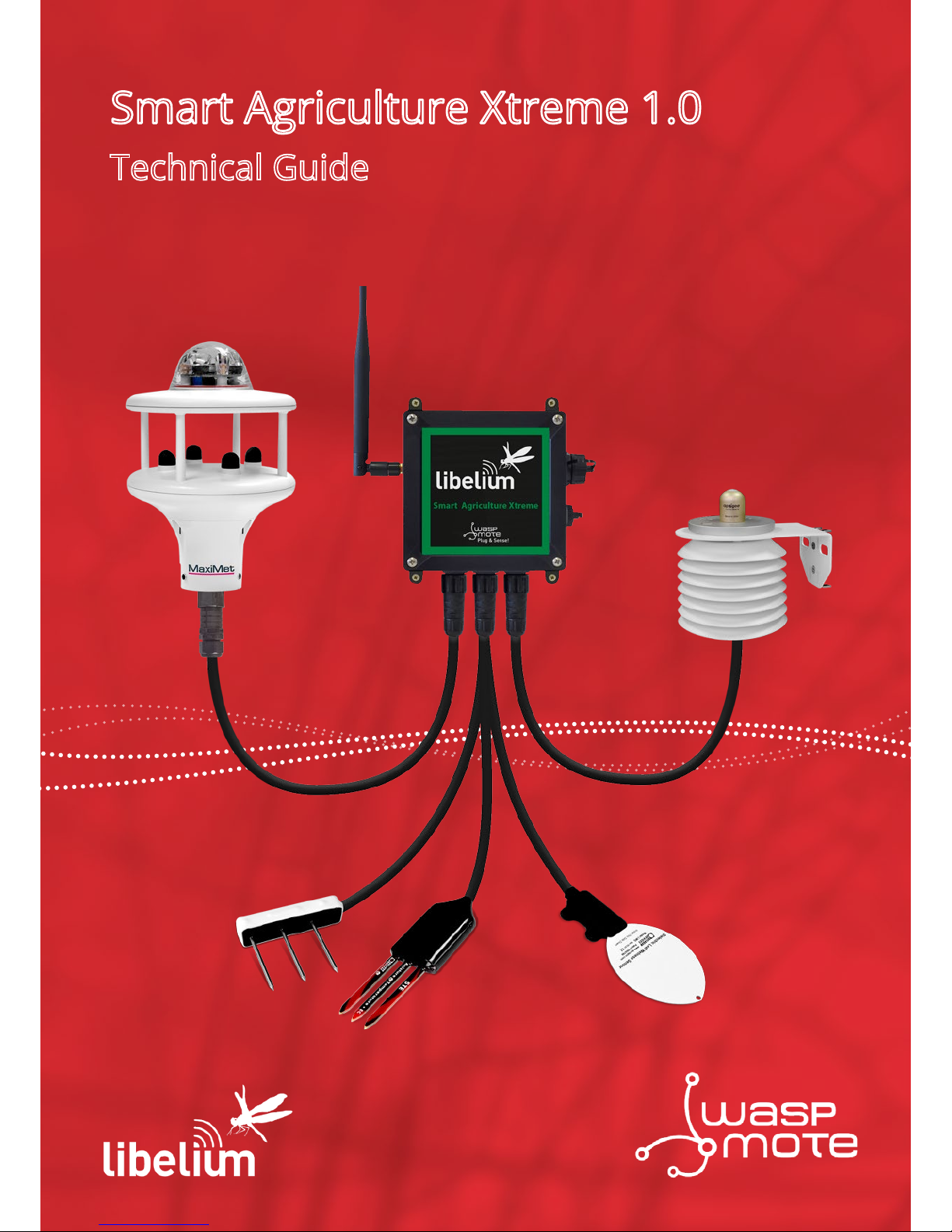
Smart Agriculture Xtreme 1.0
Technical Guide
Page 2

-2-
v7.2
Index
Document version: v.7.2 - 03/2019
© Libelium Comunicaciones Distribuidas S.L.
INDEX
1. General and safety information ......................................................................................................... 6
2. Important: Read before use ................................................................................................................ 7
3. Waspmote Plug & Sense! ..................................................................................................................... 8
3.4. Sensor probes .............................................................................................................................................................................14
3.5. Solar powered ............................................................................................................................................................................ 15
3.6. External Battery Module ......................................................................................................................................................... 16
3.7. Programming the Nodes ........................................................................................................................................................ 17
3.8. Program in minutes ..................................................................................................................................................................18
3.9. Radio interfaces ......................................................................................................................................................................... 19
3.10. Industrial Protocols ................................................................................................................................................................ 20
3.11. GPS ...............................................................................................................................................................................................22
3.12. Models ........................................................................................................................................................................................ 23
3.12.1. Smart Agriculture Xtreme .....................................................................................................................................24
4. Sensors probes .................................................................................................................................. 27
4.1. General comments ................................................................................................................................................................... 27
4.2. Non-contact surface temperature measurement sensor probe (Apogee SI-411) .............................................28
4.2.1. Specications ...............................................................................................................................................................28
4.2.2. Measurement process ..............................................................................................................................................29
4.2.3. Socket .............................................................................................................................................................................29
4.2.4. Installation ....................................................................................................................................................................30
4.2.5. Application examples ...............................................................................................................................................31
4.2.6. Certicate of calibration ..........................................................................................................................................31
4.3. Leaf and ower bud temperature sensor probe (Apogee SF-421) .........................................................................32
4.3.1. Specications ...............................................................................................................................................................32
4.3.2. Measurement process ..............................................................................................................................................33
4.3.3. Socket .............................................................................................................................................................................33
4.3.4. Installation ....................................................................................................................................................................34
4.3.5. Application examples ...............................................................................................................................................35
4.3.6. Quality Assurance Certicate .................................................................................................................................35
4.4. Soil oxygen level sensor probe (Apogee SO-411) ......................................................................................................... 36
4.4.1. Specications ...............................................................................................................................................................37
4.4.2. Measurement process ..............................................................................................................................................37
4.4.3. Socket .............................................................................................................................................................................38
4.4.4. Installation ....................................................................................................................................................................39
4.4.5. Application examples ...............................................................................................................................................40
4.4.6. Quality Assurance Certicate .................................................................................................................................40
4.5. Shortwave radiation sensor probe (Apogee SP-510) ..................................................................................................41
Page 3

-3-
v7.2
Index
4.5.1. Specications ...............................................................................................................................................................41
4.5.2. Measurement process ..............................................................................................................................................42
4.5.3. Socket .............................................................................................................................................................................42
4.5.4. Installation ....................................................................................................................................................................43
4.5.5. Application examples ...............................................................................................................................................45
4.5.6. Certicate of calibration ..........................................................................................................................................45
4.6. Solar radiation sensor probe for Smart Agriculture Xtreme (Apogee SQ-110) ..................................................46
4.6.1. Specications ...............................................................................................................................................................47
4.6.2. Measurement process ..............................................................................................................................................47
4.6.3. Socket .............................................................................................................................................................................48
4.6.4. Installation ....................................................................................................................................................................48
4.6.5. Application examples ...............................................................................................................................................50
4.6.6. Certicate of calibration ..........................................................................................................................................50
4.7. Ultraviolet radiation sensor probe for Smart Agriculture Xtreme (Apogee SU-100) ........................................ 51
4.7.1. Specications ...............................................................................................................................................................52
4.7.2. Measurement process ..............................................................................................................................................52
4.7.3. Socket .............................................................................................................................................................................53
4.7.4. Installation ....................................................................................................................................................................53
4.7.5. Application examples ...............................................................................................................................................55
4.7.6. Certicate of calibration ..........................................................................................................................................55
4.8. Temperature, humidity and pressure sensor probe (Bosch BME280) ................................................................... 56
4.8.1. Specications ...............................................................................................................................................................56
4.8.2. Measurement process ..............................................................................................................................................57
4.8.3. Socket .............................................................................................................................................................................57
4.8.4. Application examples ...............................................................................................................................................58
4.9. Conductivity, water content and soil temperature GS3 sensor probe (Decagon GS3) ................................... 59
4.9.1. Specications ...............................................................................................................................................................60
4.9.2. Measurement process ..............................................................................................................................................60
4.9.3. Socket .............................................................................................................................................................................61
4.9.4. Installation ....................................................................................................................................................................61
4.9.5. Application examples ...............................................................................................................................................62
4.9.6. Quality Assurance Certicate .................................................................................................................................62
4.10. Conductivity, water content and soil temperature 5TE sensor probe (Decagon 5TE) ................................. 63
4.10.1. Specications ............................................................................................................................................................64
4.10.2. Measurement process ............................................................................................................................................64
4.10.3. Socket ..........................................................................................................................................................................65
4.10.4. Installation ..................................................................................................................................................................66
4.10.5. Application examples.............................................................................................................................................66
4.10.6. Quality Assurance Certicate ..............................................................................................................................66
4.11. Soil temperature and volumetric water content sensor probe (Decagon 5TM) ............................................. 67
4.11.1. Specications ............................................................................................................................................................68
4.11.2. Measurement process ............................................................................................................................................68
4.11.3. Socket ..........................................................................................................................................................................69
4.11.4. Installation ..................................................................................................................................................................69
4.11.5. Application examples.............................................................................................................................................70
Page 4

-4-
v7.2
4.11.6. Quality Assurance Certicate ..............................................................................................................................70
4.12. Soil water potential sensor probe (Decagon MPS-6) .................................................................................................71
4.12.1. Specications ............................................................................................................................................................72
4.12.2. Measurement process ............................................................................................................................................72
4.12.3. Socket ..........................................................................................................................................................................73
4.12.4. Installation ..................................................................................................................................................................73
4.12.5. Application examples.............................................................................................................................................74
4.12.6. Quality Assurance Certicate ..............................................................................................................................74
4.13. Vapor pressure, temperature, barometric pressure and relative humidity sensor (Decagon VP-4) .........75
4.13.1. Specications ............................................................................................................................................................76
4.13.2. Measurement process ............................................................................................................................................78
4.13.3. Socket ..........................................................................................................................................................................79
4.13.4. Installation ..................................................................................................................................................................79
4.13.5. Application examples.............................................................................................................................................80
4.13.6. Quality Assurance Certicate ..............................................................................................................................80
4.14. Leaf wetness Phytos 31 sensor probe (Decagon Phytos 31) .................................................................................81
4.14.1. Specications ............................................................................................................................................................82
4.14.2. Measurement process ............................................................................................................................................82
4.14.3. Socket ..........................................................................................................................................................................82
4.14.4. Installation .................................................................................................................................................................83
4.14.5. Application examples.............................................................................................................................................83
4.14.6. Quality Assurance Certicate ..............................................................................................................................83
4.15. Dendrometer sensor probes for Smart Agriculture Xtreme (Ecomatik DC2, DD-S and DF) ........................84
4.15.1. Ecomatik DC2 specications (Trunk diameter) ............................................................................................84
4.15.2. Ecomatik DD-S specications (Stem diameter) ............................................................................................85
4.15.3. Ecomatik DF specications (Fruit diameter) ..................................................................................................85
4.15.4. Measurement process ............................................................................................................................................85
4.15.5. Socket ..........................................................................................................................................................................86
4.15.6. Installation .................................................................................................................................................................87
4.15.7. Application examples.............................................................................................................................................87
4.16. Weather station sensor probes (Gill Instruments MaxiMet series) ...................................................................... 88
4.16.1. MaxiMet GMX-100 (PO) sensor probe ..............................................................................................................89
4.16.2. MaxiMet GMX-101 (R) sensor probe .................................................................................................................89
4.16.3. MaxiMet GMX-200 (W) sensor probe ...............................................................................................................90
4.16.4. MaxiMet GMX-240 (W-PO) sensor probe ........................................................................................................91
4.16.5. MaxiMet GMX-300 (T-H-AP) sensor probe ......................................................................................................92
4.16.6. MaxiMet GMX-301 (T-H-AP-R) sensor probe ..................................................................................................92
4.16.7. MaxiMet GMX-400 (PO-T-H-AP) sensor probe ...............................................................................................93
4.16.8. MaxiMet GMX-500 (W-T-H-AP) sensor probe.................................................................................................94
4.16.9. MaxiMet GMX-501 (W-T-H-AP-R) sensor probe.............................................................................................95
4.16.10. MaxiMet GMX-531 (W-PT-T-H-AP-R) sensor probe ....................................................................................96
4.16.11. MaxiMet GMX-541 (W-PO-T-H-AP-R) sensor probe ...................................................................................97
4.16.12. MaxiMet GMX-550 (W-x-T-H-AP) sensor probe ..........................................................................................98
4.16.13. MaxiMet GMX-551 (W-x-T-H-AP-R) sensor probe ......................................................................................99
4.16.14. MaxiMet GMX-600 (W-PO-T-H-AP) sensor probe ...................................................................................100
Index
Page 5

-5-
v7.2
4.16.15. Specications for each weather station sensor ....................................................................................... 101
4.16.16. Measurement process ......................................................................................................................................102
4.16.17. Socket ..................................................................................................................................................................... 103
4.16.18. Installation ............................................................................................................................................................ 103
4.16.20. Product test report ............................................................................................................................................106
4.17. Solar radiation and temperature Datasol MET probe (Atersa Datasol MET) ...................................................107
4.17.1. Specications ......................................................................................................................................................... 107
4.17.2. Measurement process ......................................................................................................................................... 108
4.17.3. Socket .......................................................................................................................................................................108
4.17.4. Installation ...............................................................................................................................................................109
4.17.5. Application examples..........................................................................................................................................112
4.17.6. Certicate of calibration ..................................................................................................................................... 112
4.18. Luminosity sensor (AMS TSL2561) ..................................................................................................................................113
4.18.1. Specications ......................................................................................................................................................... 113
4.18.2. Measurement process ......................................................................................................................................... 114
4.18.3. Socket .......................................................................................................................................................................114
4.18.4. Application examples..........................................................................................................................................114
4.19. Ultrasound sensor probe (Maxbotix MB7040) ..........................................................................................................115
4.19.1. Specications ......................................................................................................................................................... 115
4.19.2. Measurement process ......................................................................................................................................... 116
4.19.3. Socket .......................................................................................................................................................................116
4.19.4. Installation ...............................................................................................................................................................117
4.19.5. Application examples..........................................................................................................................................117
5. Board conguration and programming ........................................................................................118
5.1. Hardware conguration .......................................................................................................................................................118
5.2. API .................................................................................................................................................................................................118
5.2.1. Before starting to program .................................................................................................................................. 118
5.2.2. Sending sensor values with the Frame class ................................................................................................. 119
6. Consumption ................................................................................................................................... 120
6.1. Consumption table.................................................................................................................................................................120
7. API changelog .................................................................................................................................. 121
8. Documentation changelog ............................................................................................................. 122
9. Certications .................................................................................................................................... 123
10. Maintenance ................................................................................................................................. 124
11. Disposal and recycling ................................................................................................................. 125
Page 6

-6-
v7.2
General and safety information
1. General and safety information
Important:
• All documents and any examples they contain are provided as-is and are subject to change without notice.
Except to the extent prohibited by law, Libelium makes no express or implied representation or warranty of
any kind with regard to the documents, and specically disclaims the implied warranties and conditions of
merchantability and tness for a particular purpose.
• The information on Libelium’s websites has been included in good faith for general informational purposes
only. It should not be relied upon for any specic purpose and no representation or warranty is given as to its
accuracy or completeness.
• Read carefully Limited Warranty and Terms and Conditions of Use before using “Waspmote Plug & Sense!”.
• Do not open casing and do not damage black warranty stickers. If you do so, you will lose warranty.
• Do not remove any of the connectors.
• Do not allow contact between metallic objects and electronic parts to avoid injury and burns.
• Never immerse equipment in any liquid.
• Keep equipment within temperature range indicated in recommendation section.
• Do not connect or power equipment using cables that have been damaged.
• Place equipment in an area to which only maintenance personnel can have access (in a restricted access zone).
• In any case keep children away from the equipment.
• If there is a power failure, immediately disconnect from the mains.
• If using a battery whether or not in combination with a solar panel as a power source follow the voltage and
current specications indicated in the section “External solar panel connector”.
• If a software failure occurs, contact Libelium technical support before doing any action by yourself.
• Do not place equipment on trees or plants as they could be damaged by its weight.
• Be particularly careful if you are connected through a software interface for handling the machine; if settings
of that interface are incorrectly altered, it could become inaccessible.
• If you need to clean the node, wipe it with a dry towel.
• If Waspmote Plug & Sense! needs to be returned please send it completely dry and free from contaminants.
• Waspmote Plug & Sense! is not designed to be placed in hard environmental conditions, under dangerous
chemical elements, explosive atmospheres with ammable gases, high voltage installations or special
installations. Please contact Libelium technical support to ensure your application is compatible with
Waspmote Plug & Sense!
Page 7

-7-
v7.2
Important: Read before use
2. Important: Read before use
The following list shows just some of the actions that produce the most common failures and warranty-voiding.
Complete documentation about usage can be found at http://www.libelium.com/development. Failure to comply
with the recommendations of use will entail the warranty cancellation.
Software:
• Upload code only using Waspmote IDE. If a dierent IDE is used, Waspmote can be damaged and can become
unresponsive. This use is not covered under warranty.
• Do not unplug any connector while uploading code. Waspmote can become unresponsive. This use is not
covered under warranty.
• Do not connect or disconnect any connector while Waspmote is on. Waspmote can become unstable or
unresponsive, and internal parts can be damaged. This fact is not covered under warranty.
Hardware:
• Do not handle black stickers seals on both sides of the enclosure ( Warranty stickers). Their integrity is the
proof that Waspmote Plug & Sense! has not been opened. If they have been handled, damaged or broken, the
warranty is void.
• Do not open Waspmote Plug & Sense! in any case. This will automatically make the warranty void.
• Do not handle the four metallic screws of Waspmote Plug & Sense!. They ensure waterproof seal.
• Do not submerge Waspmote Plug & Sense! in liquids.
• Do not place nodes on places or equipment where it could be exposed to shocks and/or big vibrations.
• Do not expose Waspmote Plug & Sense! to temperatures below -20 ºC or above 60 ºC.
• Do not power Waspmote with other power sources than the original provided by Libelium. Voltage and current
maximum ratings can be exceeded, stopping Waspmote working and voiding warranty.
• Do not try to extract, screw, break or move Waspmote Plug & Sense! connectors far from necessary usage,
waterproof sealing can be damaged and warranty will be voided.
• For more information: http://www.libelium.com
• Do not connect any sensor on the solar panel connector and also do not connect the solar panel to any of
sensor connectors. Waspmote can be damaged and warranty void.
• Do not connect any sensor not provided by Libelium.
• Do not place Waspmote Plug & Sense! where water can reach internal parts of sensors.
• Do not get the magnet close to a metal object. The magnet is really powerful and will get stuck.
• Do not place the magnet close to electronic devices, like PCs, batteries, etc, they could be damaged, or
information could be deleted.
Page 8
-8-
v7.2
Waspmote Plug & Sense!
3. Waspmote Plug & Sense!
This section shows main parts of Waspmote Plug & Sense! and a brief description of each one. In later sections
all parts will be described deeply.
3.1. Specications
• Material: polycarbonate
• Sealing: polyurethane
• Cover screws: stainless steel
• Ingress protection: IP65
• Impact resistance: IK08
• Rated insulation voltage AC: 690 V
• Rated insulation voltage DC: 1000 V
• Heavy metals-free: Yes
• Weatherproof: true - nach UL 746 C
• Ambient temperature (min.): -30 °C*
• Ambient temperature (max.): 70 °C*
• Approximated weight: 800 g
* Temporary extreme temperatures are supported. Regular recommended usage: -20, +60 ºC.
In the pictures included below it is shown a general view of Waspmote Plug & Sense! main parts. Some elements
are dedicated to node control, others are designated to sensor connection and other parts are just identication
elements. All of them will be described along this guide.
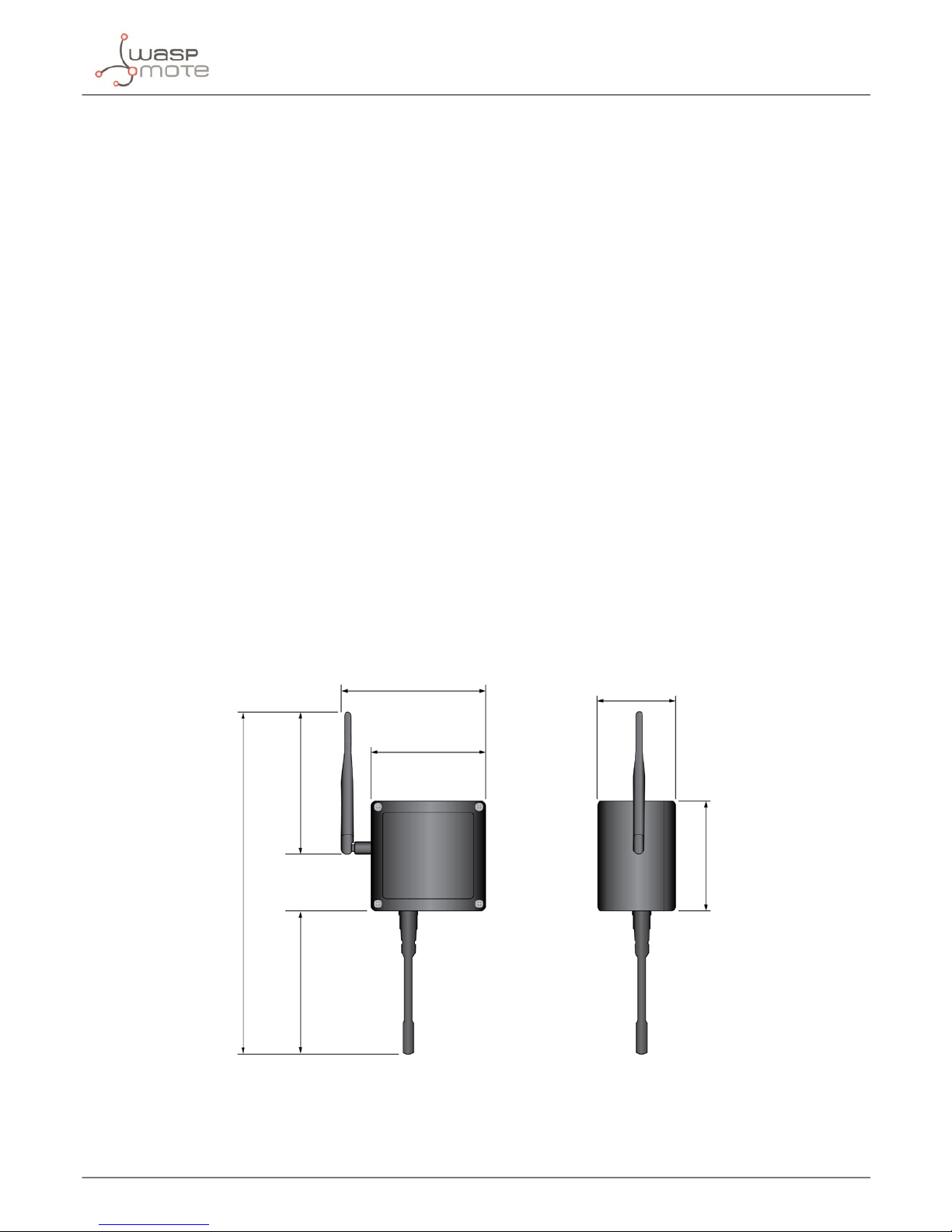
164 mm
124 mm
175 mm
410 mm
160 mm
122 mm
85 mm
Figure: Main view of Waspmote Plug & Sense!
Page 9
-9-
v7.2
Waspmote Plug & Sense!
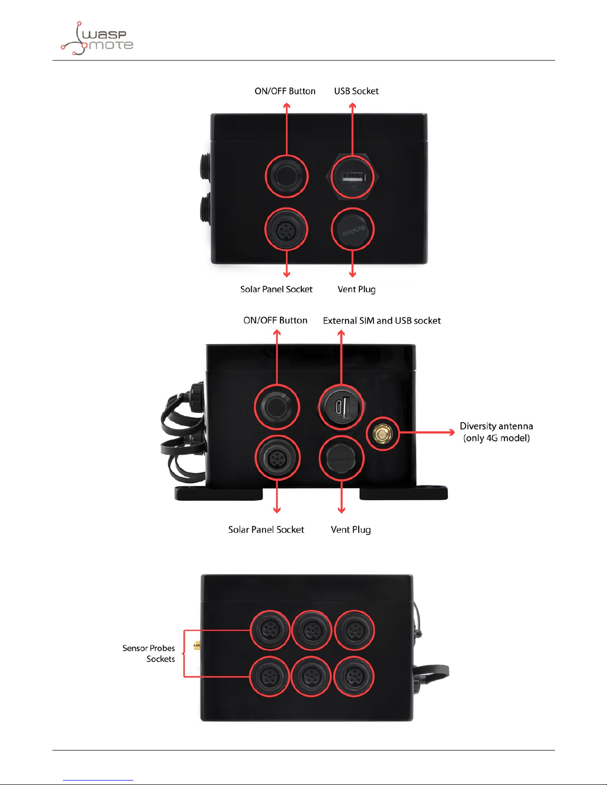
Figure: Control side of the enclosure
Control side of the enclosure for 4G model
Figure: Sensor side of the enclosure
Page 10
-10-
v7.2
Waspmote Plug & Sense!
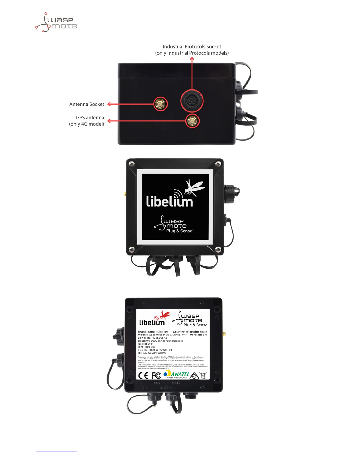
Figure: Antenna side of the enclosure
Figure: Front view of the enclosure
Figure: Back view of the enclosure
Page 11
-11-
v7.2
Waspmote Plug & Sense!
Figure: Warranty stickers of the enclosure
Important note: Do not handle black stickers seals of the enclosure (Warranty stickers). Their integrity is the proof
that Waspmote Plug & Sense! has not been opened. If they have been handled, damaged or broken, the warranty is
automatically void.
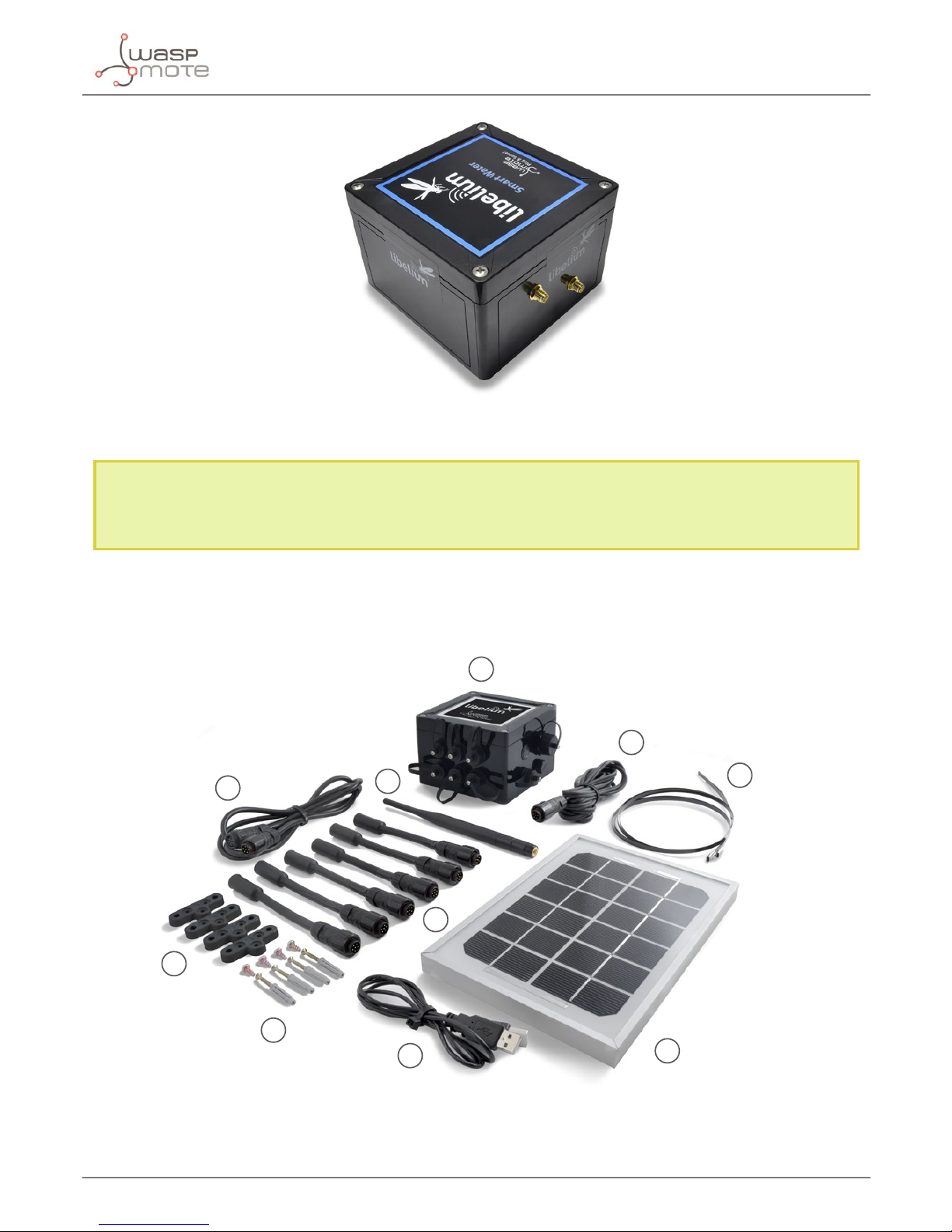
3.2. Parts included
Next picture shows Waspmote Plug & Sense! and all of its elements. Some of them are optional accessories that
may not be included.
1
2
3
4
5
7
6
8
9
10
Figure: Waspmote Plug & Sense! accessories: 1 enclosure, 2 sensor probes, 3 external solar panel, 4 USB cable, 5 antenna, 6 cable ties,
7 mounting feet (screwed to the enclosure), 8 extension cord, 9 solar panel cable, 10 wall plugs & screws
Page 12
-12-
v7.2
Waspmote Plug & Sense!
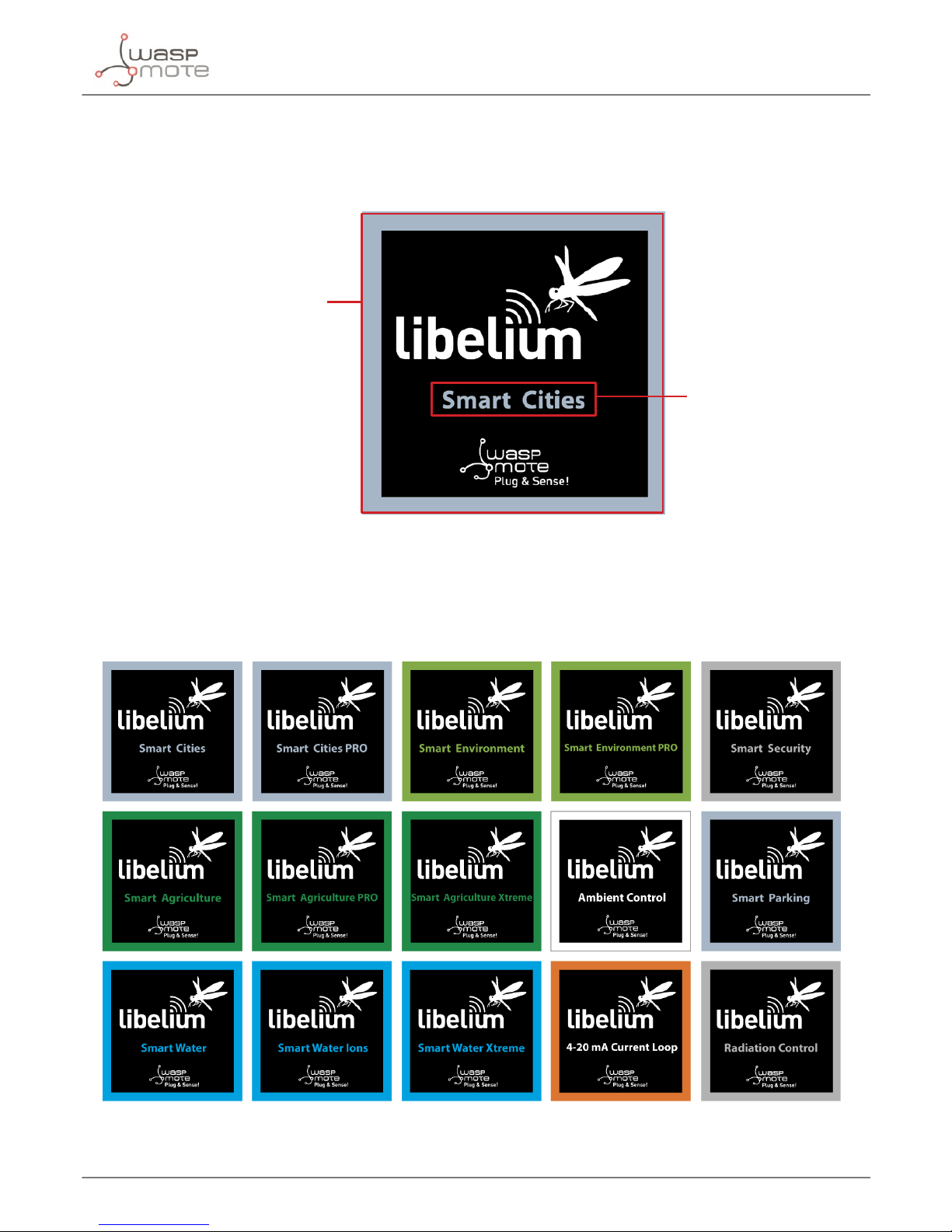
3.3. Identication
Each Waspmote model is identied by stickers. Next gure shows front sticker.
Model identication colour
Enclosure model
Figure: Front sticker of the enclosure
There are many congurations of Waspmote Plug & Sense! line, all of them identied by one unique sticker. Next
image shows all possibilities.
Figure: Dierent front stickers
Page 13
-13-
v7.2
Waspmote Plug & Sense!
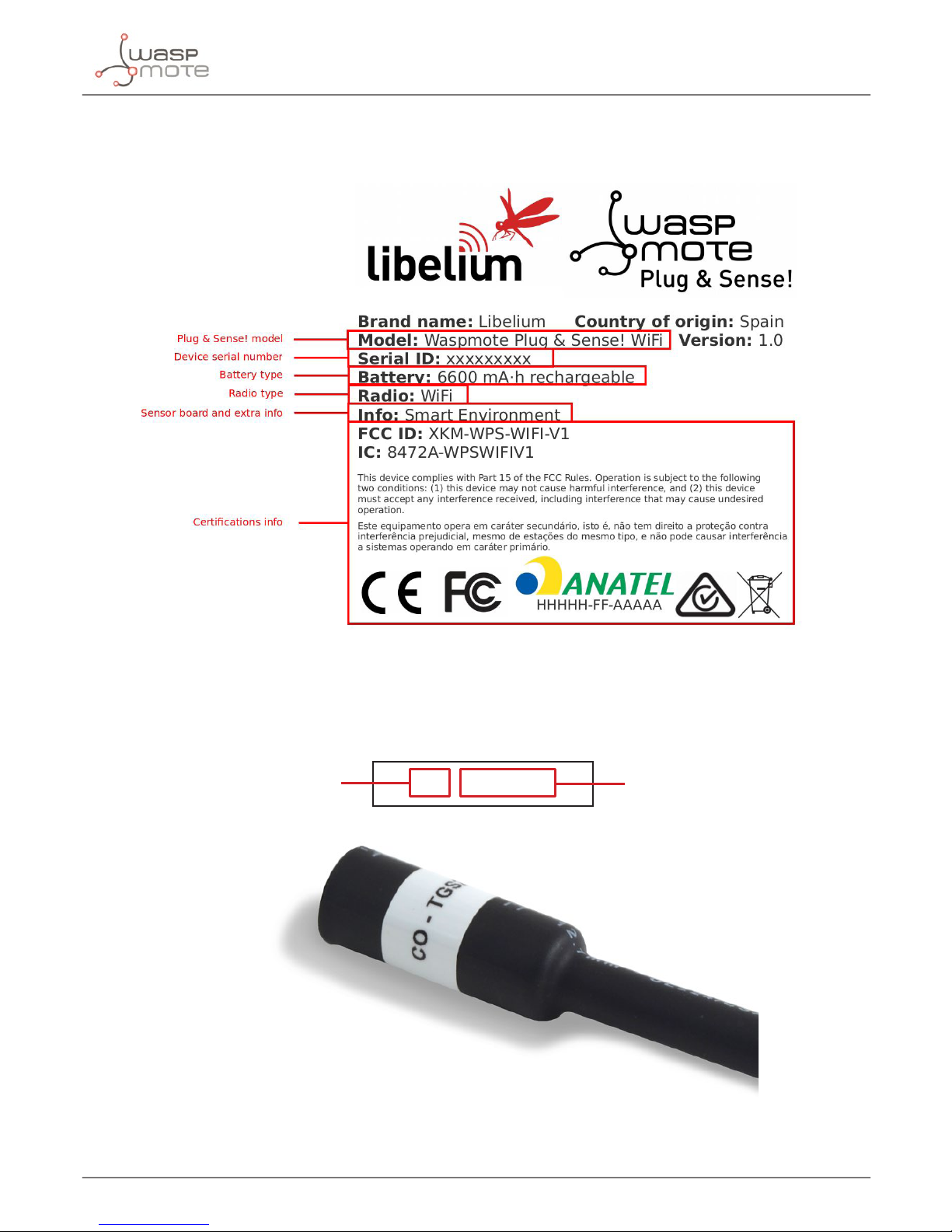
Moreover, Waspmote Plug & Sense! includes a back sticker where it is shown identication numbers, radio MAC
addresses, etc. It is highly recommended to annotate this information and save it for future maintenance. Next
gure shows it in detail.
Figure: Back sticker
Sensor probes are identied too by a sticker showing the measured parameter and the sensor manufacturer
reference.
CO - TGS2442
Measure
parameter
Sensor
reference
Figure: Sensor probe identication sticker
Page 14
-14-
v7.2
Waspmote Plug & Sense!
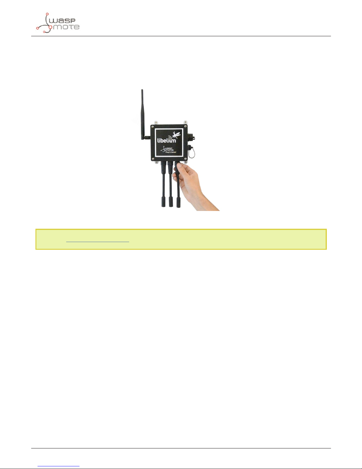
3.4. Sensor probes
Sensor probes can be easily attached by just screwing them into the bottom sockets. This allows you to add new
sensing capabilities to existing networks just in minutes. In the same way, sensor probes may be easily replaced
in order to ensure the lowest maintenance cost of the sensor network.
Figure: Connecting a sensor probe to Waspmote Plug & Sense!
Go to the Plug & Sense! Sensor Guide to know more about our sensor probes.
Page 15
-15-
v7.2
Waspmote Plug & Sense!
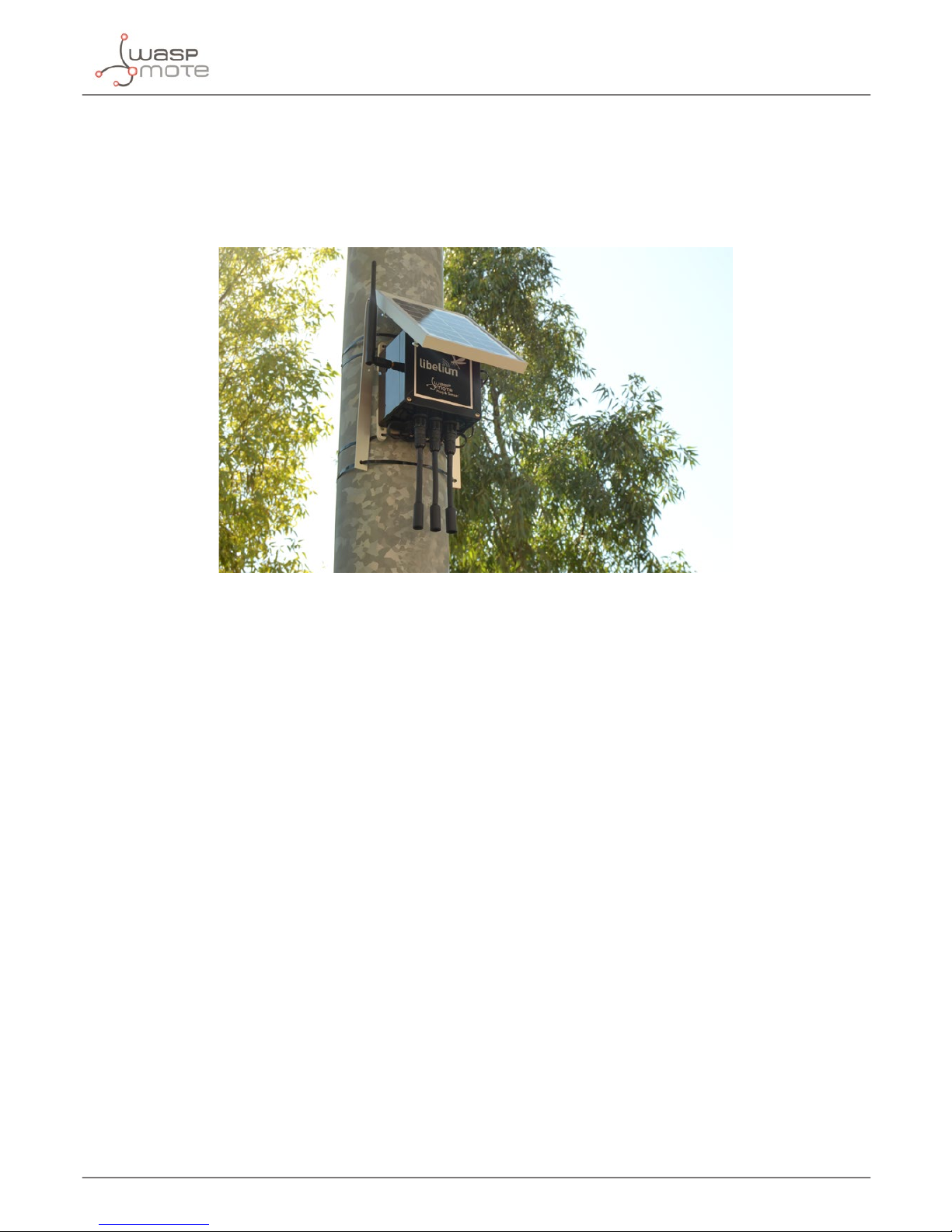
3.5. Solar powered
The battery can be recharged using the waterproof USB cable but also the external solar panel option.
The external solar panel is mounted on a 45º holder which ensures the maximum performance of each outdoor
installation.
Figure: Waspmote Plug & Sense! powered by an external solar panel
Page 16
-16-
v7.2
Waspmote Plug & Sense!
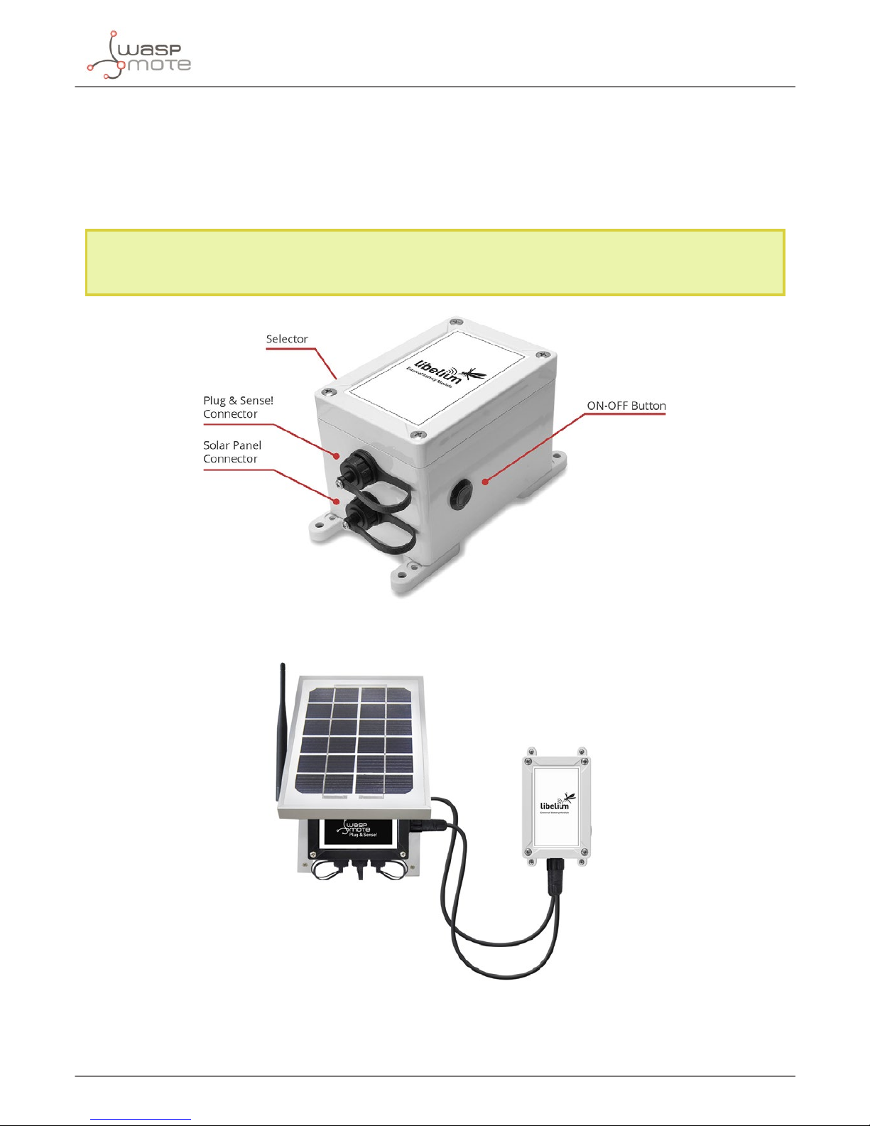
3.6. External Battery Module
The External Battery Module (EBM) is an accessory to extend the battery life of Plug & Sense!. The extension
period may be from months to years depending on the sleep cycle and radio activity. The daily charging period is
selectable among 5, 15 and 30 minutes with a selector switch and it can be combined with a solar panel to extend
even more the node’s battery lifetime.
Note: Nodes using solar panel can keep using it through the External Battery Module. The EBM is connected to
the solar panel connector of Plug & Sense! and the solar panel unit is connected to the solar panel connector
of the EBM.
Figure: Plug & Sense! with External Battery Module
Figure: Plug & Sense! with External Battery Module and solar panel
Page 17
-17-
v7.2
Waspmote Plug & Sense!
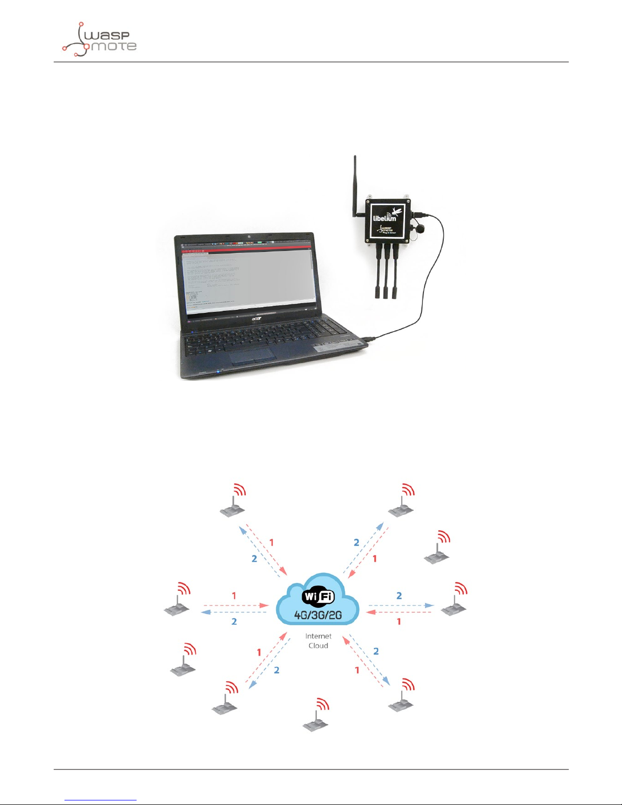
3.7. Programming the Nodes
Waspmote Plug & Sense! can be reprogrammed in two ways:
The basic programming is done from the USB port. Just connect the USB to the specic external socket and then
to the computer to upload the new rmware.
Figure: Programming a node
Over the Air Programming (OTAP) is also possible once the node has been installed (via WiFi or 4G radios). With
this technique you can reprogram, wireless, one or more Waspmote sensor nodes at the same time by using a
laptop and Meshlium.
Figure: Typical OTAP process
Page 18
-18-
v7.2
Waspmote Plug & Sense!
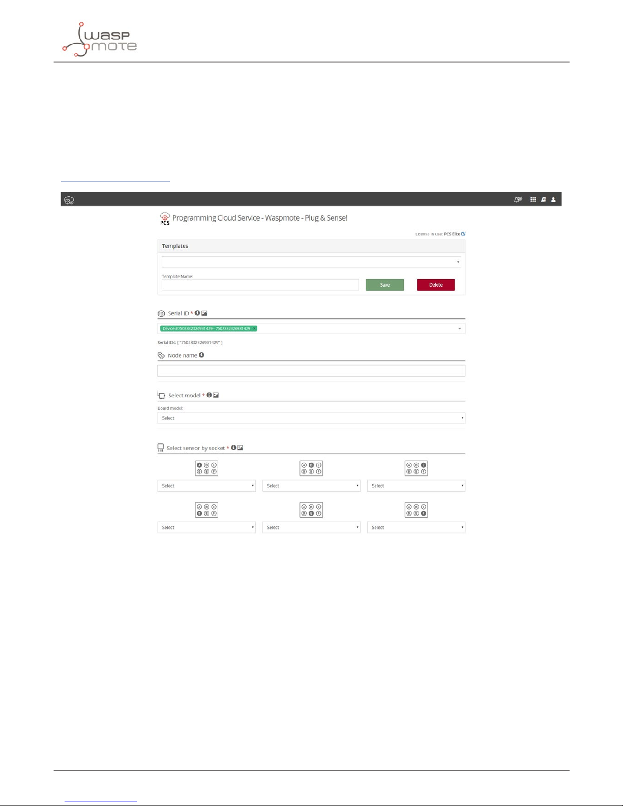
3.8. Program in minutes
The Programming Cloud Service is an intuitive graphic interface which creates code automatically. The user just
needs to to ll a web form to obtain binaries for Plug & Sense!. Advanced programming options are available,
depending on the license selected.
Check how easy it is to handle the Programming Cloud Service at:
https://cloud.libelium.com/
Figure: Programming Cloud Service
Page 19
-19-
v7.2
Waspmote Plug & Sense!
3.9. Radio interfaces
Radio Protocol
Frequency
bands
Transmission
power
Sensitivity Range*
Certication
XBee-PRO 802.15.4
EU
802.15.4 2.4 GHz 10 dBm -100 dBm 750 m CE
XBee-PRO 802.15.4 802.15.4 2.4 GHz 18 dBm -100 dBm 1600 m
FCC, IC, ANATEL,
RCM
XBee 868LP RF 868 MHz 14 dBm -106 dBm 8.4 km CE
XBee 900HP US RF 900 MHz 24 dBm -110 dBm 15.5 km FCC, IC
XBee 900HP BR RF 900 MHz 24 dBm -110 dBm 15.5 km ANATEL
XBee 900HP AU RF 900 MHz 24 dBm -110 dBm 15.5 km RCM
WiFi
WiFi
(HTTP(S),
FTP, TCP,
UDP)
2.4 GHz 17 dBm -94 dBm 500 m
CE, FCC, IC,
ANATEL, RCM
4G EU/BR
4G/3G/2G
(HTTP, FTP,
TCP, UDP)
GPS
800, 850, 900,
1800, 2100, 2600
MHz
4G: class 3
(0.2 W, 23 dBm)
4G: -102
dBm
- km - Typical
base station
range
CE, ANATEL
4G US
4G/3G/2G
(HTTP, FTP,
TCP, UDP)
GPS
700, 850, 1700,
1900 MHz
4G: class 3
(0.2 W, 23 dBm)
4G: -103
dBm
- km - Typical
base station
range
FCC, IC, PTCRB,
AT&T
4G AU
4G
(HTTP, FTP,
TCP, UDP)
700, 1800, 2600
MHz
4G: class 3
(0.2 W, 23 dBm)
4G: -102
dBm
- km - Typical
base station
range
RCM
Sigfox EU Sigfox 868 MHz 16 dBm -126 dBm
- km - Typical
base station
range
CE
Sigfox US Sigfox 900 MHz 24 dBm -127 dBm
- km - Typical
base station
range
FCC, IC
Sigfox AU / APAC /
LATAM
Sigfox 900 MHz 24 dBm -127 dBm
- km - Typical
base station
range
-
LoRaWAN EU LoRaWAN 868 MHz 14 dBm -136 dBm > 15 km CE
LoRaWAN US LoRaWAN 902-928 MHz 18.5 dBm -136 dBm > 15 km FCC, IC
LoRaWAN AU LoRaWAN 915-928 MHz 18.5 dBm -136 dBm > 15 km -
LoRaWAN IN LoRaWAN 865-867 MHz 18.5 dBm -136 dBm > 15 km
-
LoRaWAN ASIA-PAC
/ LATAM
LoRaWAN 923 MHz 18.5 dBm -136 dBm > 15 km
-
* Line of sight and Fresnel zone clearance with 5dBi dipole antenna.
Page 20
-20-
v7.2
Waspmote Plug & Sense!
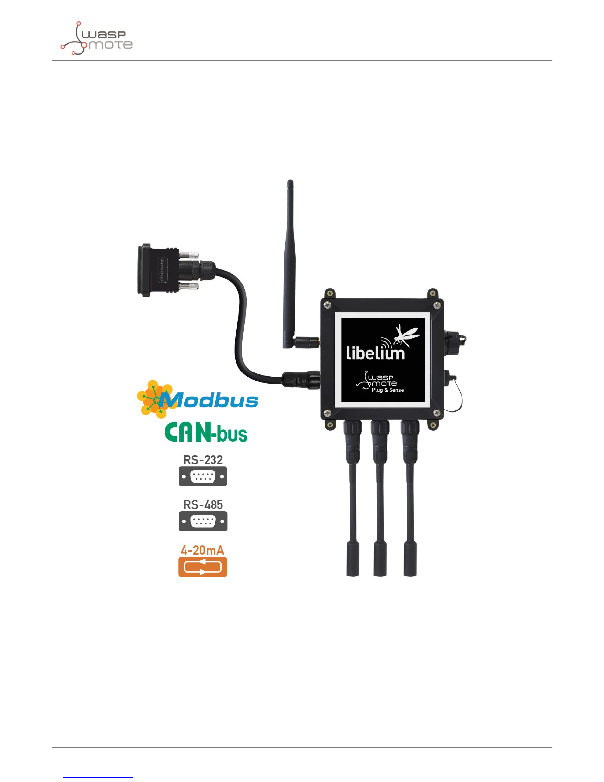
3.10. Industrial Protocols
Besides the main radio of Waspmote Plug & Sense!, it is possible to have an Industrial Protocol module as a
secondary communication option. This is oered as an accessory feature.
The available Industrial Protocols are RS-485, Modbus (software layer over RS-485) and CAN Bus. This optional
feature is accessible through an additional, dedicated socket on the antenna side of the enclosure.
Figure: Industrial Protocols available on Plug & Sense!
Page 21
-21-
v7.2
Waspmote Plug & Sense!
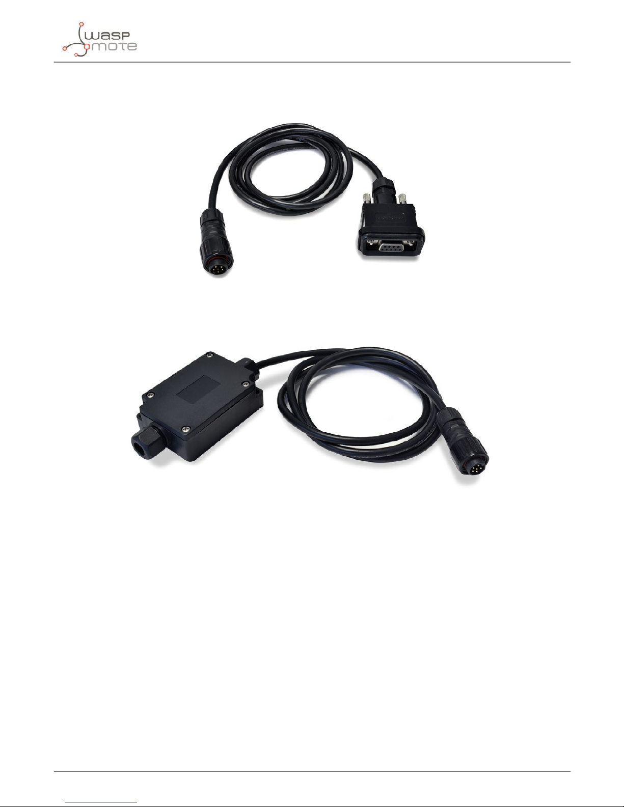
Finally, the user can choose between 2 probes to connect the desired Industrial Protocol: A standard DB9 connector
and a waterproof terminal block junction box. These options make the connections on industrial environments or
outdoor applications easier.
Figure: DB9 probe
Figure: Terminal box probe
Page 22
-22-
v7.2
Waspmote Plug & Sense!
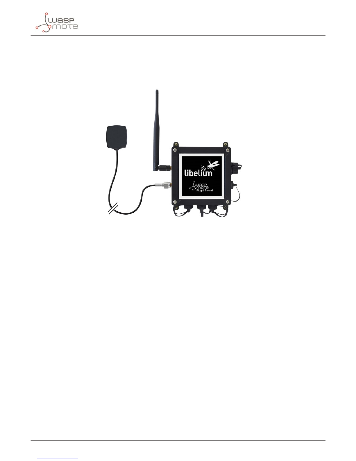
3.11. GPS
Any Plug & Sense! node can incorporate a GPS receiver in order to implement real-time asset tracking applications.
The user can also take advantage of this accessory to geolocate data on a map. An external, waterproof antenna
is provided; its long cable enables better installation for maximum satellite visibility.
Figure: Plug & Sense! node with GPS receiver
Chipset: JN3 (Telit)
Sensitivity:
• Acquisition: -147 dBm
• Navigation: -160 dBm
• Tracking: -163 dBm
Hot start time: <1 s
Cold start time: <35 s
Positional accuracy error < 2.5 m
Speed accuracy < 0.01 m/s
EGNOS, WAAS, GAGAN and MSAS capability
Antenna:
• Cable length: 2 m
• Connector: SMA
• Gain: 26 dBi (active)
Available information: latitude, longitude, altitude, speed, direction, date&time and ephemeris management
Page 23
-23-
v7.2
Waspmote Plug & Sense!
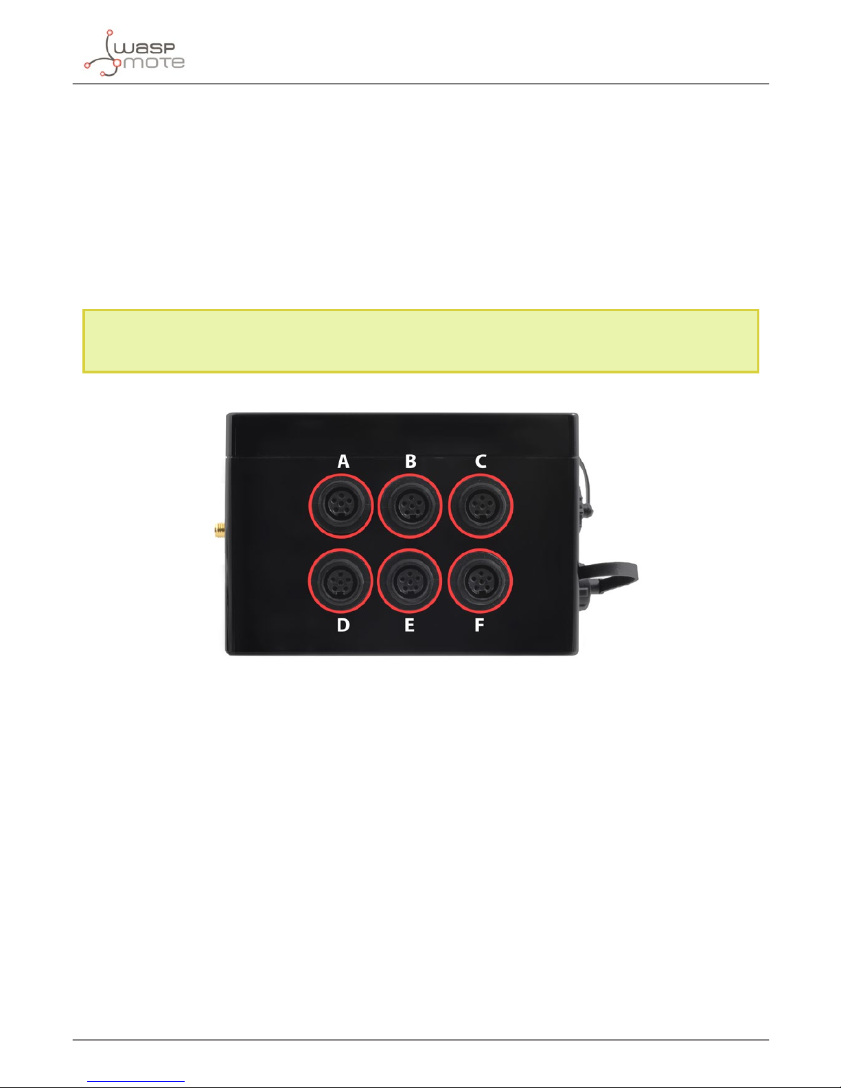
3.12. Models
There are some dened congurations of Waspmote Plug & Sense! depending on which sensors are going to be
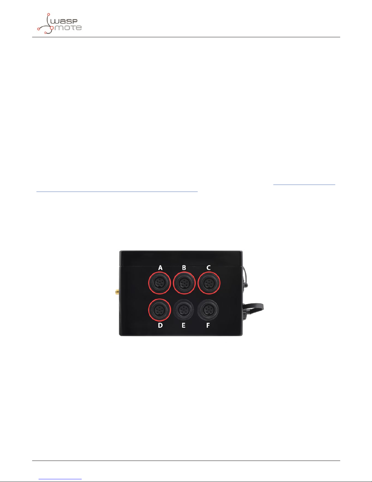
used. Waspmote Plug & Sense! congurations allow to connect up to six sensor probes at the same time.
Each model takes a dierent conditioning circuit to enable the sensor integration. For this reason each model
allows to connect just its specic sensors.
This section describes each model conguration in detail, showing the sensors which can be used in each case
and how to connect them to Waspmote. In many cases, the sensor sockets accept the connection of more than
one sensor probe. See the compatibility table for each model conguration to choose the best probe combination
for the application.
It is very important to remark that each socket is designed only for one specic sensor, so they are not
interchangeable. Always be sure you connected probes in the right socket, otherwise they can be damaged.
Figure: Identication of sensor sockets
Page 24
-24-
v7.2
Waspmote Plug & Sense!
3.12.1. Smart Agriculture Xtreme
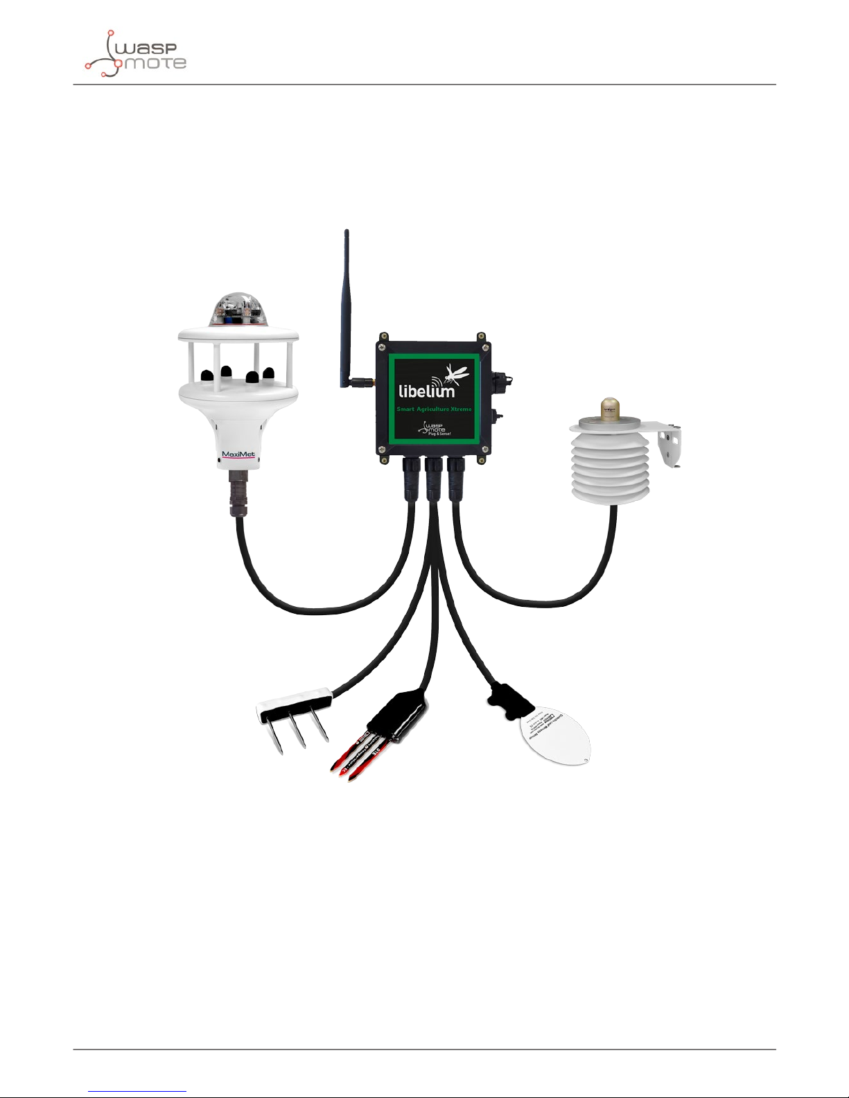
The Plug & Sense! Smart Agriculture Xtreme is an evolution of our Agriculture line with a new selection of highend professional sensors. It allows to monitor multiple environmental parameters involving a wide range of
applications, from plant growing analysis to weather observation. There are sensors for atmospheric and soil
monitoring and plants health. Up to 33 sensors can be connected.
Figure: Smart Agriculture Xtreme Waspmote Plug & Sense! model
Page 25
-25-
v7.2
Waspmote Plug & Sense!
Sensor sockets are congured as shown in the gure below.
Sensor
Socket
Sensor probes allowed for each sensor socket
Parameter Reference
A and D
Non-contact surface temperature measurement SI-411 9468-P
Leaf and ower bud temperature SF-421 9467-P
Soil oxygen level SO-411 9469-P
Conductivity, water content and soil temperature 5TE 9402-P
Conductivity, water content and soil temperature GS3 9464-P
Soil temperature and volumetric water content 5TM 9460-P
Soil water potential MPS-6 9465-P
Vapor pressure, humidity, temperature, and atmospheric
pressure in soil and air VP-4
9471-P
Temperature, air humidity and pressure 9370-P
Luxes 9325-P
Ultrasound 9246-P
B
Non-contact surface temperature measurement SI-411 9468-P
Leaf and ower bud temperature SF-421 9467-P
Soil oxygen level SO-411 9469-P
Conductivity, water content and soil temperature 5TE 9402-P
Conductivity, water content and soil temperature GS3 9464-P
Soil temperature and volumetric water content 5TM 9460-P
Soil water potential MPS-6 9465-P
Vapor pressure, humidity, temperature, and atmospheric
pressure in soil and air VP-4
9471-P
Leaf wetness Phytos 31 9466-P
Shortwave radiation SP-510 9470-P
Solar radiation (PAR) SQ-110 for Smart Agriculture Xtreme 9251-PX
Ultraviolet radiation SU-100 for Smart Agriculture Xtreme 9257-PX
4-20 mA type (generic) -
C
Non-contact surface temperature measurement SI-411 9468-P
Leaf and ower bud temperature SF-421 9467-P
Soil oxygen level SO-411 9469-P
Conductivity, water content and soil temperature 5TE 9402-P
Conductivity, water content and soil temperature GS3 9464-P
Soil temperature and volumetric water content 5TM 9460-P
Soil water potential MPS-6 9465-P
Vapor pressure, humidity, temperature, and atmospheric
pressure in soil and air VP-4
9471-P
Dendrometers (DC2, DD-S, DF) for Smart Agriculture Xtreme 9252-PX, 9253-PX, 9254-PX
Shortwave radiation SP-510 9470-P
Solar radiation (PAR) SQ-110 for Smart Agriculture Xtreme 9251-PX
Ultraviolet radiation SU-100 for Smart Agriculture Xtreme 9257-PX
Page 26
-26-
v7.2
Waspmote Plug & Sense!
E
Shortwave radiation SP-510 9470-P
Solar radiation (PAR) SQ-110 for Smart Agriculture Xtreme 9251-PX
Ultraviolet radiation SU-100 for Smart Agriculture Xtreme 9257-PX
Weather station GMX-100 (PO) Probe 9472-P
Weather station GMX-101 (R) 9473-P
Weather station GMX-200 (W) 9474-P
Weather station GMX-240 (W-PO) 9463-P
Weather station GMX-300 (T-H-AP) 9475-P
Weather station GMX-301 (T-H-AP-R) 9476-P
Weather station GMX-400 (PO-T-H-AP) 9477-P
Weather station GMX-500 (W-T-H-AP) 9478-P
Weather station GMX-501 (W-T-H-AP-R) 9479-P
Weather station GMX-531 (W-PT-T-H-AP-R) 9480-P
Weather station GMX-541 (W-PO-T-H-AP-R) 9481-P
Weather station GMX-550 (W-x-T-H-AP) 9482-P
Weather station GMX-551 (W-x-T-H-AP-R) 9483-P
Weather station GMX-600 (W-PO-T-H-AP) 9484-P
Solar radiation and temperature Datasol MET probe 9496-P
F
Shortwave radiation SP-510 9470-P
Solar radiation (PAR) SQ-110 for Smart Agriculture Xtreme 9251-PX
Ultraviolet radiation SU-100 for Smart Agriculture Xtreme 9257-PX
RS-232 type (generic) -
4-20 mA type (generic) -
Figure: Sensor sockets configuration for Smart Agriculture model
Note: For more technical information about each sensor probe go to the Development section on the Libelium
website.
Page 27

-27-
v7.2
Sensors probes
4. Sensors probes
4.1. General comments
The following sections describe the main features and the general usage for all the sensors probes included in the
Plug & Sense! Smart Agriculture Xtreme model.
It is important to remark that Smart Agriculture Xtreme is only available in the Waspmote Plug & Sense! line. It is
not available for the Waspmote OEM line. Besides, keep in mind that Smart Agriculture Xtreme is not compatible
with the former Smart Agriculture or Smart Agriculture PRO models. In other words, the sensor probes described
in this Guide are only compatible with Smart Agriculture Xtreme, because its advanced electronics allow these
specic sensor integrations (some exceptions are the BME, Ultrasound or Luminosity sensors).
In order to keep this guide as short as possible, some manufacturer information has been omitted. Libelium
encourages the reader to visit the manufacturer websites and to spend some time studying all the technical papers
and application notes provided for each sensor. Measured parameters on the great majority of Smart Agriculture
applications require a deep knowledge of the environmental parameters and, what is a more, sophisticated
measure techniques to obtain the best accuracy.
Additionally, Libelium highly recommends to carry out comprehensive laboratory tests before installing the system
on the eld, as well as proof of concepts on the eld during a reasonable period, before going to a real deploy.
Thanks to these good practices, the user will have an idea of the platform behavior, which will be very close to the
reality. Parameters like accuracy over time or battery drain can be only measured with real tests.
Finally, always take into account a maintenance factor for each sensor probe. The environmental conditions could
aect the sensor behaviour and accuracy therefore it will become mandatory a periodic maintenance for each
sensor probe, to watch out things like dirty on sensor probes, measure position or wire connections. The period
between these maintenance actions will be dierent on each application. Contact our Sales department through
the next link if you require more information: http://www.libelium.com/contact.
Page 28
-28-
v7.2
Sensors probes
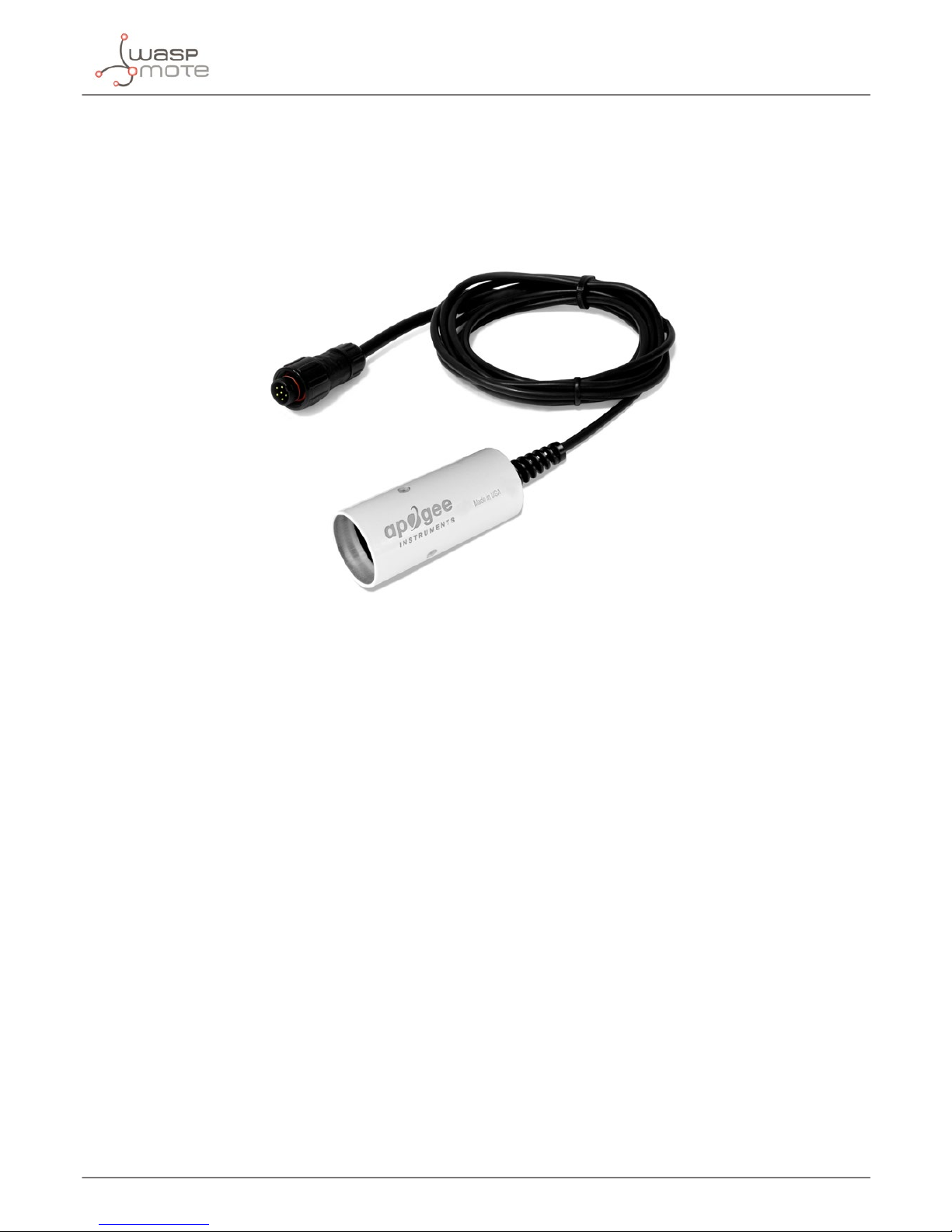
4.2. Non-contact surface temperature measurement sensor probe (Apogee SI-411)
The Non-contact surface temperature measurement sensor probe is able to measure the electromagnetic radiation
that every object with a temperature above absolute zero emits, which is used to calculate surface temperature
from a distance. Thanks to this, the temperature of the object surface is not altered in any way when measuring it.
Figure: The non-contact surface temperature measurement sensor probe (Apogee SI-411)
4.2.1. Specications
• Operating environment: -45 to 80 ºC
• Operation humidity: 0 ~ 100% RH (non-condesing)
• Calibration uncertainty (-20 to 65 ºC), when target and detector temperature are within 20 ºC: 0.2 ºC
• Calibration uncertainty (-40 to 80 ºC), when target and detector temperature are dierent by more than
20 ºC: 0.5 ºC
• Measurement repeatability: less than 0.05 ºC
• Stability (Long-term drift): less than 2 % change in slope per year when germanium lter is maintained in a
clean condition
• Field of view: 22º half angle
• Spectral range: 8 to 14 µm; atmospheric window
• Dimensions: 23 mm diameter; 60 mm length
• Mass: 190 g (with 5m of lead wire)
• Cable: 5 m
Page 29
-29-
v7.2
Sensors probes
4.2.2. Measurement process
The SI-411 sensor provides a digital signal using the SDI-12 protocol.
Reading code:
{
// 1. Declare an object for the sensor
Apogee_SI411 mySensor(XTR_SOCKET_A);
// 2. Turn ON the sensor
mySensor.ON();
// 3. Read the sensor. Values stored in class variables
// Check complete code example for details
mySensor.read();
// 4. Turn off the sensor
mySensor.OFF();
}
You can nd a complete example code for reading this sensor probe in the following link: http://www.libelium.com/
development/waspmote/examples/ag-xtr-01-SI-411-sensor-reading
4.2.3. Socket
Connect the infrared radiometer sensor to the Plug & Sense! Smart Agriculture Xtreme in any of the sockets
shown in the image below.
Figure: Available sockets for the SI-411 sensor probe
Page 30
-30-
v7.2
Sensors probes
4.2.4. Installation
When choosing the distance of the sensor to the object to be measured at the installation of the sensor, it must be
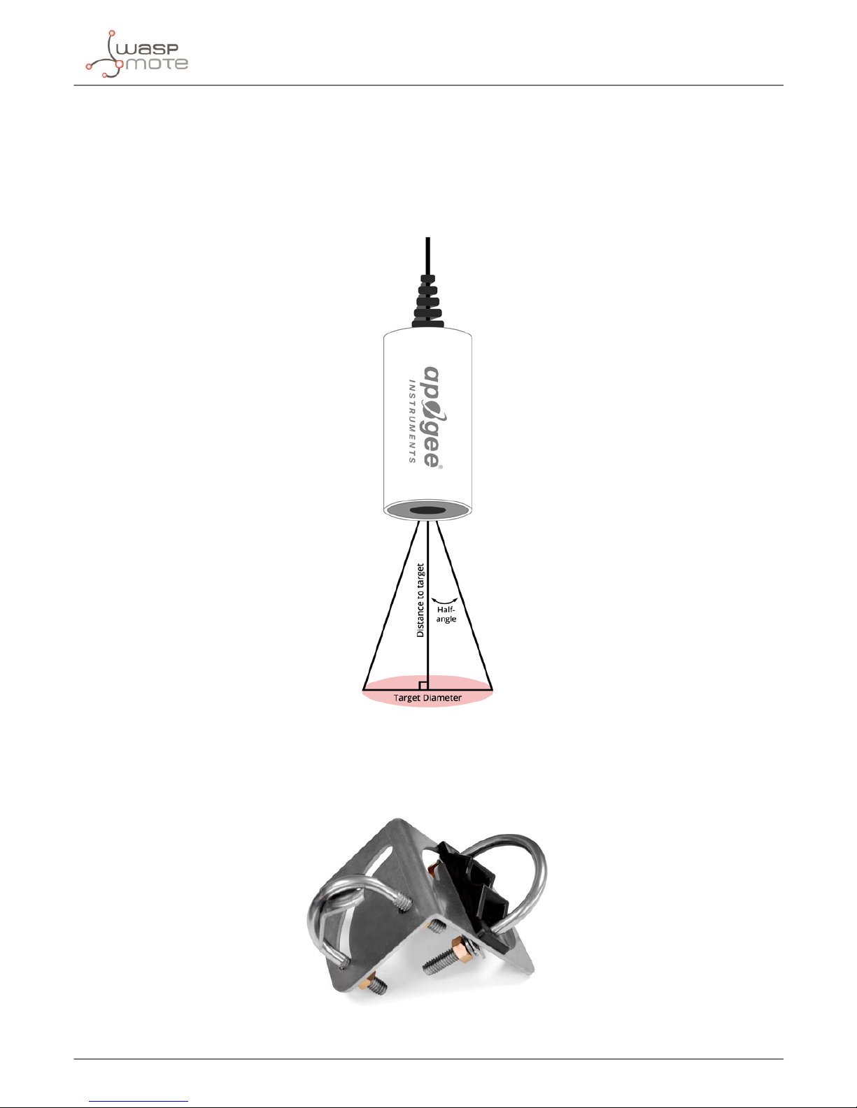
taken into account that it has a eld of view (FOV) of 22º (half angle), as you can see in the image below.
It is necessary to remove the green protective cover to measure, it is only used to protect the sensor when it is
not being used.
Figure: Sensor eld of view
An Angle mounting bracket (Apogee AM-220) can also be used for the installation. This accessory is recommended
to mount the sensor on a pole with an outer diameter from 3.3 to 5.3 cm in dierent angles.
Figure: Angle mounting bracket (Apogee AM-220)
Page 31

-31-
v7.2
Sensors probes
Looking into above picture, the black plastic part on the right must be facing the pole, while the metal angled part
on the left must x the sensor.
First, attach the accessory to the pole screwing the 2 nuts just enough to hold the accessory to the pole. Keep the
2 washers to avoid the installation loosening.
Then, place the sensor into the accessory, taking into account that the sensor must point towards the desired
target.
Finally, adjust the angles by rotating the sensor and hold it into the desired position while the nuts are tightened.
Figure: Angle mounting bracket installation with the SI-411 sensor
You can nd the complete sensor manual on the manufacturer’s website.
4.2.5. Application examples
• Plant canopy temperature measurement for plant water status estimation
• Road surface temperature measurement for determination of icing conditions
• Terrestrial surface (soil, vegetation, water, snow) temperature measurement in energy balance studies
4.2.6. Certicate of calibration
Together with this sensor we provide a calibration certicate in which the manufacturer ensures that the sensor
has passed a calibration procedure with traceability to an accredited laboratory.
Page 32

-32-
v7.2
Sensors probes
4.3. Leaf and ower bud temperature sensor probe (Apogee SF-421)
Frost events may happen in plants even though the ambient temperature is not 0 ºC or lower because the canopy
temperature can be dierent than air temperature, this is called radiation frost. The Leaf and bud temperature
sensor probe is designed to predict frost events.
Radiation frost occurs when there is a lack of air mixing by the wind near the surface and a negative net long wave
radiation balance at the surface.
Figure: Leaf and bud temperature sensor probe (Apogee SF-421)
4.3.1. Specications
• Operating temperature: -50 to 70 ºC
• Operation humidity: 0 ~ 100% RH
• Measurement range: -50 to 70 ºC
• Measurement Uncertainty:
- 0.1 ºC (from 0 to 70 ºC)
- 0.2 ºC (from -25 to 0 ºC)
- 0.4 ºC (from -50 to -25 ºC)
• Measurement repeatability: less than 0.05 ºC
• Stability (Long-term drift): Less than 0.02 ºC per year
• Equilibration time: 10 s
• Self-heating: Less than 0.01 ºC
• Dimensions: 57 cm length, 2.1 cm pipe diameter, 7.0 cm disk diameter (see image below)
• Mass: 400 g
• Cable: 5 m
Figure: Radiation frost detector dimensions
Page 33

-33-
v7.2
Sensors probes
4.3.2. Measurement process
The SF-421 sensor provides a digital signal using the SDI-12 protocol.
Reading code:
{
// 1. Declare an object for the sensor
Apogee_SI421 mySensor(XTR_SOCKET_A);
// 2. Turn ON the sensor
mySensor.ON();
// 3. Read the sensor. Values stored in class variables
// Check complete code example for details
mySensor.read();
// 4. Turn off the sensor
mySensor.OFF();
}
You can nd a complete example code for reading this sensor probe in the following link: http://www.libelium.com/
development/waspmote/examples/ag-xtr-02-SF-421-sensor-reading
4.3.3. Socket
Connect the SF-421 sensor probe to Plug & Sense! Smart Agriculture Xtreme in any of the sockets shown in the
image below.
Figure: Available sockets for the SF-421 sensor probe
Page 34

-34-
v7.2
Sensors probes
4.3.4. Installation
The shape of the SF-421 sensor is designed to resemble a plant leaf and ower bud and be able to measure
radiation frost events. The sensor should be installed near the plant canopy where the radiation frost detection
is required.
Figure: SF-421 sensor installation
An Angle mounting bracket (Apogee AM-220) can also be used for the installation. This accessory is recommended
to mount the sensor on a pole with an outer diameter from 3.3 to 5.3 cm in dierent angles.
Figure: Angle mounting bracket (Apogee AM-220)
Looking into above picture, the black plastic part on the right must be facing the pole, while the metal angled
part on the left must x the sensor.
First, attach the accessory to the pole screwing the 2 nuts just enough to hold the accessory to the pole. Keep the
2 washers to avoid the installation loosening.
Then, place the sensor into the accessory, taking into account that the sensor must point towards the desired
target.
Page 35

-35-
v7.2
Sensors probes
Finally, adjust the angles by rotating the sensor and hold it into the desired position while the nuts are tightened.
Figure: Angle mounting bracket installation with the SF-421 sensor
You can nd the complete sensor manual on the manufacturer’s website.
4.3.5. Application examples
• Leaf and bud temperature estimates in cropped elds, orchards, and vineyards.
• Detection of potential frost damage to crops.
4.3.6. Quality Assurance Certicate
Together with this sensor we provide a quality assurance certicate in which the manufacturer ensures that the
sensor has passed the internal quality procedures.
Page 36

-36-
v7.2
Sensors probes
4.4. Soil oxygen level sensor probe (Apogee SO-411)
Oxygen is the second major constituent of Earth’s atmosphere and it is crucial for the development of life. There
are sensors which measures oxygen in 2 states: dissolved in a solution and in a gaseous state. The Soil oxygen
level sensor probe measures gaseous oxygen.
The Soil oxygen level sensor probe consists of a galvanic cell type sensor and oers a measure of the percentage
of the total number of molecules of oxygen in the air. This sensor is specially designed for use in soil or porous
media.
Figure: Soil oxygen level sensor probe (Apogee SO-411)
Figure: SO-411 sensor with diusion head AO-001
Page 37

-37-
v7.2
Sensors probes
4.4.1. Specications
• Operating environment: -20 to 60 ºC; 60 to 114 kPa
• Operation humidity: 0 ~ 100% RH (non-condensing)
• Measurement range: 0 to 100 % O
2
• Measurement repeatability: Less than 0.1 % of mV output at 20.95 % O
2
• Non-linearity: Less than 1 %
• Long-term drift (Non-stability): 1.0 mV per year
• Oxygen consumption rate: 2.2 µmol O2 per day at 20.95 % O2 and 23 ºC
• Response time: 60 s
• Dimensions: 32 mm diameter, 68 mm length
• Mass: 175 g
• Cable: 5 m
4.4.2. Measurement process
The SO-411 sensor provides a digital signal using the SDI-12 protocol.
Reading code:
{
// 1. Declare an object for the sensor
Apogee_SO411 mySensor(XTR_SOCKET_A);
// 2. Turn ON the sensor
mySensor.ON();
// 3. Initialization delay, necessary for this sensor
delay(60000);
// 4. Read the sensor. Values stored in class variables
// Check complete code example for details
mySensor.read();
// 5. Turn off the sensor
mySensor.OFF();
}
You can nd a complete example code for reading this sensor probe in the following link: http://www.libelium.com/
development/waspmote/examples/ag-xtr-03-SO-411-sensor-reading
Page 38

-38-
v7.2
Sensors probes
4.4.3. Socket
Connect the SO-411 sensor probe to Plug & Sense! Smart Agriculture Xtreme in any of the sockets shown in the
image below.
Figure: Available sockets for the SO-411 sensor probe
Page 39

-39-
v7.2
Sensors probes
4.4.4. Installation
The SO-411 sensor is designed to be installed in soil or porous media in vertical position, with the opening pointing
down and the cable pointing up.
This sensor can be used with the accessory model A0-001, designed to facilitate measurements in soil or porous
media. It consists of a diusion head that maintains an air pocket and provides protection to the teon membrane
where gas diusion occurs.
Figure: Diusion head accessory A0-001
Figure: SO-411 sensor installation with diusion head accessory
You can nd the complete sensor manual on the manufacturer’s website.
Page 40

-40-
v7.2
Sensors probes
4.4.5. Application examples
• Measurement of O2 in laboratory experiments.
• Monitoring gaseous O2 in indoor environments for climate control.
• Monitoring of O2 levels in compost piles and mine tailings.
• Monitoring redox potential in soils.
• Determination of respiration rates through measurement of O2 consumption in sealed chambers.
• Measurement of O2 gradients in soil/porous media.
4.4.6. Quality Assurance Certicate
Together with this sensor we provide a quality assurance certicate in which the manufacturer ensures that the
sensor has passed the internal quality procedures.
Page 41

-41-
v7.2
Sensors probes
4.5. Shortwave radiation sensor probe (Apogee SP-510)
The Shortwave radiation sensor probe (Apogee SP-510) measures incoming global shortwave radiation from the
Sun. Shortwave radiation is radiant energy with wavelengths in the visible (VIS), near-ultraviolet (UV), and nearinfrared (NIR) spectra.
This sensor consists of a thermopile detector, acrylic diuser, heater, and signal processing circuitry mounted in
an anodized aluminum housing.
Figure: Shortwave radiation sensor probe (Apogee SP-510)
4.5.1. Specications
General specications
• Operating temperature: -50 to 80 ºC
• Operation humidity: 0 ~ 100% RH
• Sensitivity (variable from sensor to sensor, typical values listed): 0.057 mV per W m
-2
• Calibration factor (reciprocal of sensitivity): 17.5 W m-2 per mV
• Calibration uncertainty: ± 5%
• Calibrated output range: 0 to 114 mV
• Measurement range: 0 to 2000 W m-2 (net shortwave radiation)
• Measurement repeatability: less than 1%
• Long-term drift (non-stability): less than 2% per year
• Non-linearity: less than 1%
• Detector response time: 0.5 s
• Field of view: 180º
• Spectral range (wavelengths where response is 50% of maximum): 385 to 2105 nm
• Directional (cosine) response: less than 30 W m-2 up to solar zenith angles of 80º
• Temperature response: less than 5% from -15 to 45 ºC
• Cable length: 5 m
Page 42

-42-
v7.2
Sensors probes
4.5.2. Measurement process
The SP-510 sensor provides an analog signal.
Reading code:
{
// 1. Declare an object for the sensor
Apogee_SP510 mySensor(XTR_SOCKET_B);
// 2. Turn ON the sensor
mySensor.ON();
// 3. Read the sensor. Values stored in class variables
// Check complete code example for details
mySensor.read();
// 4. Turn off the sensor
mySensor.OFF();
}
You can nd a complete example code for reading this sensor probe in the following link: http://www.libelium.com/
development/waspmote/examples/ag-xtr-06-SP-510-sensor-reading
4.5.3. Socket
Connect the SP-510 sensor probe to Plug & Sense! Smart Agriculture Xtreme in any of the sockets shown in the
image below.
Figure: Available sockets for the SP-510 sensor probe
Page 43

-43-
v7.2
Sensors probes
4.5.4. Installation
The SP-510 sensor includes a nylon mounting screw on the base in order to mount the sensor on a solid surface.
Figure: Pyranometer installation
The Solar sensors mounting accessory can also be used for the installation. This accessory is optional but highly
recommended for the solar sensors. With this accessory you will get a secure fastening while keeping the sensor
as level as possible, always pointing up.
The accessory is composed of 2 main parts:
A - Mounting bracket: it will be fastened to a pipe or mast with its u-bolt
B - Leveling plate: it holds the sensor and includes a bubble level
Page 44

-44-
v7.2
Sensors probes
Figure: Solar sensors mounting accessory
Mounting the system is very easy, just follow these steps:
1 - Attach the solar sensor to the leveling plate, in its central hole. Use the black nylon screw (every sensor comes
with one, nd it on its bottom) and a screwdriver.
2 - Fasten the leveling plate to the mounting bracket with the 3 long gray screws. Do not insert them too rmly,
the nal adjustment is done later.
3 - Decide if you want to mount the whole structure to a vertical or horizontal pipe or mast (its outer diameter can
go from 3.3 to 5.3 cm). Depending on horizontal or vertical conguration, you will use the bottom or the side of
the mounting bracket.
4 - Place the black plastic piece in contact with the pipe. Then use the u-bolt to grab the mounting bracket to the
pipe. On both ends of the u-bolt, insert rst the washers, then the lock washers and nally the nuts.
5 - Place the structure in the desired position and tighten the nuts rmly with a wrench.
Figure: Final look of the whole structure
Page 45

-45-
v7.2
Sensors probes
6 - You may take advantage of the holes on the mounting bracket and the pipe to secure the cable of the sensor,
avoiding its rotation. You can do that with some cable ties. To minimize azimuth error, the sensor should be
mounted with the cable pointing toward true north in the northern hemisphere or true south in the southern
hemisphere. Azimuth error is typically less than 1%, but it is easy to minimize by proper cable orientation.
7 - Once installed, use the long gray screws of the plate for ne adjustment of the level, making sure the bubble is
inside the black circle. The wave spring will keep the leveling plate in place.
Note: the sensor should be mounted so that obstructions (pipe/mast, sensors, enclosures, leaves, walls, etc) do
not shade the sensor.
You can nd the complete sensor manual on the manufacturer’s website.
4.5.5. Application examples
• Incoming shortwave radiation measurement in agricultural, ecological, and hydrological weather networks
• Optimization of photo-voltaic systems
4.5.6. Certicate of calibration
Together with this sensor we provide a calibration certicate in which the manufacturer ensures that the sensor
has passed a calibration procedure with traceability to an accredited laboratory.
Page 46

-46-
v7.2
Sensors probes
4.6. Solar radiation sensor probe for Smart Agriculture
Xtreme (Apogee SQ-110)
Photosynthetically active radiation (PAR) is the radiation that drives photosynthesis and is typically dened as
total radiation across a range from 400 to 700 nm. PAR is often expressed as photosynthetic photon ux density
(PPFD): photon ux in units of micromoles per square meter per second (μmol·m-2s-1).
Figure: Solar radiation sensor probe for Smart Agriculture Xtreme (Apogee SQ-110)
Figure: Graph of the spectral response of the PAR sensor (Apogee SQ-110) compared to the photosynthetic response of a plant
Page 47

-47-
v7.2
Sensors probes
4.6.1. Specications
• Operation temperature: -40 ~ 70 ºC
• Operation humidity: 0 ~ 100% RH
• Sensitivity: 0.2 mV / μmol·m-2s
-1
• Calibration factor (Reciprocal of sensitivity): 5 μmol·m-2s-1 / mV
• Non-linearity: < 1% (up to 4000 μmol·m-2s-1 / mV)
• Non-stability (long-term drift): <2% per year
• Spectral range: 410 ~ 655 nm
• Repeatability: <0.5%
• Diameter: 2.4 cm
• Height: 2.8 cm
• Cable length: 5 m
4.6.2. Measurement process
The SQ-110 sensor provides an analog signal.
Reading code:
{
// 1. Declare an object for the sensor
Apogee_SQ110 mySensor(XTR_SOCKET_B);
// 2. Turn ON the sensor
mySensor.ON();
// 3. Read the sensor. Values stored in class variables
// Check complete code example for details
mySensor.read();
// 4. Turn off the sensor
mySensor.OFF();
}
You can nd a complete example code for reading this sensor probe in the following link: http://www.libelium.com/
development/waspmote/examples/ag-xtr-05-SQ-110-sensor-reading
Page 48

-48-
v7.2
Sensors probes
4.6.3. Socket
Connect the SQ-110 sensor probe to Plug & Sense! Smart Agriculture Xtreme in any of the sockets shown in the
image below.
Note: This sensor has a specic wiring for the Plug & Sense! Smart Agriculture Xtreme model, so it is not compatible
with other Plug & Sense! models and vice versa. Refer to our Sales department for more information.
Figure: Available sockets for the SQ-110 sensor probe
4.6.4. Installation
The SQ-110 sensor includes a nylon mounting screw on the base in order to mount the sensor on a solid surface.
Figure: SQ-110 sensor installation
The Solar sensors mounting accessory can also be used for the installation. This accessory is optional but highly
recommended for the solar sensors. With this accessory you will get a secure fastening while keeping the sensor
as level as possible, always pointing up.
Page 49

-49-
v7.2
Sensors probes
The accessory is composed of 2 main parts:
A - Mounting bracket: it will be fastened to a pipe or mast with its u-bolt
B - Leveling plate: it holds the sensor and includes a bubble level
Figure: Solar sensors mounting accessory
Mounting the system is very easy, just follow these steps:
1 - Attach the solar sensor to the leveling plate, in its central hole. Use the black nylon screw (every sensor comes
with one, nd it on its bottom) and a screwdriver.
2 - Fasten the leveling plate to the mounting bracket with the 3 long gray screws. Do not insert them too rmly,
the nal adjustment is done later.
3 - Decide if you want to mount the whole structure to a vertical or horizontal pipe or mast (its outer diameter can
go from 3.3 to 5.3 cm). Depending on horizontal or vertical conguration, you will use the bottom or the side of
the mounting bracket.
4 - Place the black plastic piece in contact with the pipe. Then use the u-bolt to grab the mounting bracket to the
pipe. On both ends of the u-bolt, insert rst the washers, then the lock washers and nally the nuts.
5 - Place the structure in the desired position and tighten the nuts rmly with a wrench.
Figure: Final look of the whole structure
Page 50

-50-
v7.2
Sensors probes
6 - You may take advantage of the holes on the mounting bracket and the pipe to secure the cable of the sensor,
avoiding its rotation. You can do that with some cable ties. To minimize azimuth error, the sensor should be
mounted with the cable pointing toward true north in the northern hemisphere or true south in the southern
hemisphere. Azimuth error is typically less than 1%, but it is easy to minimize by proper cable orientation.
7 - Once installed, use the long gray screws of the plate for ne adjustment of the level, making sure the bubble is
inside the black circle. The wave spring will keep the leveling plate in place.
Note: the sensor should be mounted so that obstructions (pipe/mast, sensors, enclosures, leaves, walls, etc) do
not shade the sensor.
You can nd the complete sensor manual on the manufacturer’s website.
4.6.5. Application examples
Photosynthetic photon ux density (PPFD) measures in:
• Plant canopies in outdoor environments
• Greenhouses and growth chambers
• Evapotranspiration analysis
• Aquatic environments, including salt water aquariums where corals are grown
4.6.6. Certicate of calibration
Together with this sensor we provide a calibration certicate in which the manufacturer ensures that the sensor
has passed a calibration procedure with traceability to an accredited laboratory.
Page 51

-51-
v7.2
Sensors probes
4.7. Ultraviolet radiation sensor probe for Smart Agriculture Xtreme (Apogee SU-100)
Ultraviolet (UV) radiation is typically dened as total radiation across a range from 100 to 400 nm and is subdivided
into 3 wavelength ranges: UV-A (315 to 400 nm), UV-B (280 to 315 nm) and UV-C (100 to 280 nm). Much of the UV-B
and all of the UV-C wavelengths from the sun are absorbed by the Earth’s atmosphere.
The Ultraviolet radiation sensor probe for Smart Agriculture Xtreme (Apogee SU-100) detects UV radiation from
250 to 400 nm and is calibrated in photon ux units of micromoles per square meter per second (μmol·m-2s-1). .
Figure: Ultraviolet radiation sensor probe for Smart Agriculture Xtreme (Apogee SU-100)
Figure: Graph of the spectral response of the SU-100 sensor probe compared to the photosynthetic response of a plant
Page 52

-52-
v7.2
Sensors probes
4.7.1. Specications
• Operation temperature: -40 to 70 ºC
• Operation humidity: 0 to 100 %
• Sensitivity: 0.2 mV / μmol·m-2s
-1
• Calibration factor (reciprocal of sensitivity): 5.0 μmol·m-m-2s-1 / mV
• Non-stability (long-term drift): <3% per year
• Non-linearity: <1% (up to 300 μmol·m-2s-1)
• Spectral range: 250 ~ 400 nm
• Repeatability: <1%
• Diameter: 2.4 cm
• Height: 2.8 cm
• Cable length: 5 m
4.7.2. Measurement process
The SU-100 sensor provides an analog signal.
Reading code:
{
// 1. Declare an object for the sensor
Apogee_SU100 mySensor(XTR_SOCKET_B);
// 2. Turn ON the sensor
mySensor.ON();
// 3. Read the sensor. Values stored in class variables
// Check complete code example for details
mySensor.read();
// 4. Turn off the sensor
mySensor.OFF();
}
You can nd a complete example code for reading this sensor probe in the following link: http://www.libelium.com/
development/waspmote/examples/ag-xtr-04-SU100-sensor-reading
Page 53

-53-
v7.2
Sensors probes
4.7.3. Socket
Connect the SU-100 sensor probe to Plug & Sense! Smart Agriculture Xtreme in any of the sockets shown in the
image below.
Note: This sensor has a specic wiring for the Plug & Sense! Smart Agriculture Xtreme model, so it is not compatible
with other Plug & Sense! models and vice versa. Refer to our Sales department for more information.
Figure: Available sockets for the SU-100 sensor probe
4.7.4. Installation
The SU-100 sensor includes a nylon mounting screw on the base in order to mount the sensor on a solid surface.
Figure: SU-100 sensor probe installation
The Solar sensors mounting accessory can also be used for the installation. This accessory is optional but highly
recommended for the solar sensors. With this accessory you will get a secure fastening while keeping the sensor
as level as possible, always pointing up.
The accessory is composed of 2 main parts:
A - Mounting bracket: it will be fastened to a pipe or mast with its u-bolt.
B - Leveling plate: it holds the sensor and includes a bubble level.
Page 54

-54-
v7.2
Sensors probes
Figure: Solar sensors mounting accessory
Mounting the system is very easy, just follow these steps:
1 - Attach the solar sensor to the leveling plate, in its central hole. Use the black nylon screw (every sensor comes
with one, nd it on its bottom) and a screwdriver.
2 - Fasten the leveling plate to the mounting bracket with the 3 long gray screws. Do not insert them too rmly,
the nal adjustment is done later.
3 - Decide if you want to mount the whole structure to a vertical or horizontal pipe or mast (its outer diameter can
go from 3.3 to 5.3 cm). Depending on horizontal or vertical conguration, you will use the bottom or the side of
the mounting bracket.
4 - Place the black plastic piece in contact with the pipe. Then use the u-bolt to grab the mounting bracket to the
pipe. On both ends of the u-bolt, insert rst the washers, then the lock washers and nally the nuts.
5 - Place the structure in the desired position and tighten the nuts rmly with a wrench.
Figure: Final look of the whole structure
Page 55

-55-
v7.2
Sensors probes
6 - You may take advantage of the holes on the mounting bracket and the pipe to secure the cable of the sensor,
avoiding its rotation. You can do that with some cable ties. To minimize azimuth error, the sensor should be
mounted with the cable pointing toward true north in the northern hemisphere or true south in the southern
hemisphere. Azimuth error is typically less than 1%, but it is easy to minimize by proper cable orientation.
7 - Once installed, use the long gray screws of the plate for ne adjustment of the level, making sure the bubble is
inside the black circle. The wave spring will keep the leveling plate in place.
Note: the sensor should be mounted so that obstructions (pipe/mast, sensors, enclosures, leaves, walls, etc) do
not shade the sensor.
You can nd the complete sensor manual on the manufacturer’s website.
4.7.5. Application examples
UV radiation measurement in:
• Outdoor environments
• Laboratory use with articial light sources (e.g. germicidal lamps)
• Monitoring the lter ability and stability of dierent materials
4.7.6. Certicate of calibration
Together with this sensor we provide a calibration certicate in which the manufacturer ensures that the sensor
has passed a calibration procedure with traceability to an accredited laboratory.
Page 56

-56-
v7.2
Sensors probes
4.8. Temperature, humidity and pressure sensor probe
(Bosch BME280)
The Bosch BME280 includes a humidity sensor that features an extremely fast response time which supports
performance requirements for emerging applications such as context awareness, and high accuracy over a wide
temperature range. The pressure sensor is an absolute barometric pressure sensor with features exceptionally
high accuracy and resolution at very low noise. The integrated temperature sensor has been optimized for very
low noise and high resolution. It is primarily used for temperature compensation of the pressure and humidity
sensors, and can also be used for estimating ambient temperature.
Figure: Temperature, humidity and pressure sensor (Bosch BME280)
4.8.1. Specications
Temperature sensor
• Operational range: -40 ~ +85 ºC
• Full accuracy range: 0 ~ +65 ºC
• Accuracy: ±1 ºC (range 0 ºC ~ +65 ºC)
• Response time: 1.65 seconds (63% response from +30 to +125 °C).
Humidity sensor
• Measurement range: 0 ~ 100% of relative humidity (for temperatures < 0 °C and > 60 °C see gure below)
Accuracy: < ±3% RH (at 25 ºC, range 20 ~ 80%)
• Hysteresis: ±1% RH
• Operating temperature: -40 ~ +85 ºC
• Response time (63% of step 90% to 0% or 0% to 90%): 1 second
Figure: Humidity sensor operating range
Page 57

-57-
v7.2
Sensors probes
Pressure sensor
• Measurement range: 30 ~ 110 kPa
• Operational temperature range: -40 ~ +85 ºC
• Full accuracy temperature range: 0 ~ +65 ºC
• Absolute accuracy: ±0.1 kPa (0 ~ 65 ºC)
4.8.2. Measurement process
The Temperature, humidity and pressure sensor provides a digital signal using the I2C protocol.
Reading code:
{
// 1. Declare an object for the sensor
bme mySensor(XTR_SOCKET_A);
// 2. Turn ON the sensor
mySensor.ON();
// 3. Read the sensor. Store parameters in local variables
oattemperature=mySensor.getTemperature();
oathumidity=mySensor.getHumidity();
oatpressure=mySensor.getPressure();
// 4. Turn off the sensor
mySensor.OFF();
}
You can nd a complete example code for reading this sensor probe in the following link: http://www.libelium.com/
development/waspmote/examples/ag-xtr-16-BME280-sensor-reading
4.8.3. Socket
Connect the Temperature, humidity and pressure sensor probe (Bosch BME280) to Plug & Sense! Smart Agriculture
Xtreme in any of the sockets shown in the image below.
Figure: Available sockets for the Temperature, humidity and pressure sensor probe (Bosch BME280)
Page 58

-58-
v7.2
Sensors probes
4.8.4. Application examples
• Weather observation and forecast
• Evapotranspiration analysis
• Control heating, ventilation or air conditioning in greenhouses
• Warning regarding dryness or high temperatures
Page 59

-59-
v7.2
Sensors probes
4.9. Conductivity, water content and soil temperature GS3
sensor probe (Decagon GS3)
The Conductivity, water content and soil temperature sensor probe (Decagon GS3) can measure many types
of growing media, specially in greenhouse applications where the probe can be inserted easily into dierent
types of soilless substrates. The GS3 sensor determines volumetric water content (VWC) by measuring the
dielectric constant (εa) of the medium using capacitance / frequency-domain technology, the temperature using a
thermistor, and electrical conductivity using a stainless steel electrode array.
Figure: Conductivity, water content and soil temperature GS3 sensor probe (Decagon GS3)
Page 60

-60-
v7.2
Sensors probes
4.9.1. Specications
General specications
• Operating temperature: -40 to 60 ºC
• Dielectric measurement frequency: 70 MHz
• Measurement time: 150 ms
• Dimensions: 9.3 x 2.4 x 6.5 cm
• Prong length: 5.5 cm
• Cable length: 5 m
Volumetric water content
• Accuracy: εa: ±1 εa (unitless) from 1 to 40 (soil range), ±15% from 40 to 80
• Resolution:
- 0.1 εa (unitless) from 1 to 20
- < 0.75 εa (unitless) from 20 to 80
- 0.002 m3/ m3 (0.2% VWC) from 0 to 40% VWC
- 0.001 m3/ m3 (0.1% VWC) > 40% VWC
• Range: Apparent dielectric permittivity (εa): 1 (air) to 80 (water)
Bulk electrical conductivity
• Accuracy: ± 5% from 0 to 5 dS/m, ±10% from 5 to 23 dS/m
• Resolution: 0.001 dS/m from 0 to 23 dS/m
• Range: 0 to 25 dS/m (bulk)
Temperature
• Accuracy: ±1 ºC
• Resolution: 0.1 ºC
• Range: -40 to 60 ºC
4.9.2. Measurement process
The GS3 sensor provides a digital signal using the SDI-12 protocol.
Reading code:
{
// 1. Declare an object for the sensor
Decagon_GS3 mySensor(XTR_SOCKET_A);
// 2. Turn ON the sensor
mySensor.ON();
// 3. Read the sensor. Values stored in class variables
// Check complete code example for details
mySensor.read();
// 4. Turn off the sensor
mySensor.OFF();
}
Page 61

-61-
v7.2
Sensors probes
Volumetric water content (VWC) calculation
The GS3 sensor provides the dielectric permittivity (εa) of the surrounding medium. The dielectric permittivity
value must be converted in the code to a particular substrate by a calibration equation specic to the media you
are working in.
The calibration equation for several potting soils, perlite, and peat moss at salinities ranging from 0 to > 4 dS/m is:
The calibration equation for mineral soils ranging from 0 to > 5 dS/m is:
You can nd a complete example code for reading this sensor probe and for calculating VWC for mineral soil in the
following link: http://www.libelium.com/development/waspmote/examples/ag-xtr-07-GS3-sensor-reading
4.9.3. Socket
Connect the GS3 sensor probe to Plug & Sense! Smart Agriculture Xtreme in any of the sockets shown in the image
below.
Figure: Available sockets for the GS3 sensor probe
4.9.4. Installation
The GS3 sensor can be inserted into soilless substrates in dierent ways. However, the orientation of the sensor
does aect the sensor readings. Please keep in mind that the sensor only measures the VWC in its sphere of
inuence.
Sensors can either be inserted into the top of the plant pot or into the side of the root ball. Insertion into the side
of the root ball may be the best option, as it will give the best indication of the water available to the plant.
Page 62

-62-
v7.2
Sensors probes
Figure: GS3 sensor installation
You can nd the complete sensor manual on the manufacturer’s website.
4.9.5. Application examples
• Maintain good soil contact and compensate for air gaps in the substrate of potting soil or soilless medias
• Greenhouse substrate monitoring
• Irrigation management
• Salt management
• Fertilizer movement
• Modeling processes that are aected by temperature
4.9.6. Quality Assurance Certicate
Together with this sensor we provide a quality assurance certicate in which the manufacturer ensures that the
sensor has passed the internal quality procedures.
Page 63

-63-
v7.2
Sensors probes
4.10. Conductivity, water content and soil temperature 5TE
sensor probe (Decagon 5TE)
The Conductivity, water content and soil temperature sensor probe (Decagon 5TE) can measure volumetric water
content, electrical conductivity, and temperature of soil. The sensor uses an oscillator running at 70 MHz to
measure the dielectric permittivity of soil to determine the water content (VWC). A thermistor in thermal contact
with the sensor prongs provides the soil temperature, while the screws on the surface of the sensor form a twosensor electrical array to measure electrical conductivity.
Figure: Conductivity, water content and soil temperature 5TE sensor probe (Decagon 5TE)
Page 64

-64-
v7.2
Sensors probes
4.10.1. Specications
General specications
• Operating temperature: -40 to 60 ºC
• Dielectric measurement frequency: 70 MHz
• Measurement time: 150 ms
• Dimensions: 10 cm x 3.2 cm x 0.7 cm
• Prong length: 5.2 cm
• Cable length: 5 m
Volumetric water content
• Range: Apparent dielectric permittivity (εa): 1 (air) to 80 (water)
• Resolution:
- 0.1 εa (unitless) from 1 to 20,
- < 0.75 εa (unitless) from 20 to 80
- 0.0008 m3/ m3 (0.08% VWC) from 0 to 50% VWC
• Accuracy: εa : ±1 εa (unitless) from 1 to 40 (soil range), ±15% from 40 to 80 (VWC)
Bulk electrical conductivity
• Range: 0 to 23 dS/m (bulk)
• Resolution: 0.01 dS/m from 0 to 7 dS/m, 0.05 dS/m from 7 to 23 dS/m
• Accuracy: ±10% from 0 to 7 dS/m
Temperature
• Range: −40 to 60 ºC
• Resolution: 0.1 ºC
• Accuracy: ±1 ºC
4.10.2. Measurement process
The water content, electrical conductivity, and temperature sensor (Decagon 5TE) provides a digital signal using
SDI-12 protocol.
You can nd a complete example code for reading this sensor in the following link:
{
// 1. Declare an object for the sensor
Decagon_5TE mySensor(XTR_SOCKET_A);
// 2. Turn ON the sensor
mySensor.ON();
// 3. Read the sensor. Values stored in class variables
// Check complete code example for details
mySensor.read();
// 4. Turn off the sensor
mySensor.OFF();
}
Page 65

-65-
v7.2
Sensors probes
Volumetric water content (VWC) calculation
The 5TE sensor provides the dielectric permittivity (εa) of the surrounding medium. The dielectric permittivity
value must be converted in the code to a particular substrate by a calibration equation specic to the media you
are working in.
The calibration equation for mineral soil (Topp equation) is:
The calibration equation for potting soil is:
The calibration equation for rockwool is:
The calibration equation for perlite is:
You can nd a complete example code for reading this sensor probe and for calculating VWC for mineral soil in the
following link: http://www.libelium.com/development/waspmote/examples/ag-xtr-08-5TE-sensor-reading
4.10.3. Socket
Connect the 5TE sensor probe to Plug & Sense! Smart Agriculture Xtreme in any of the sockets shown in the image
below.
Figure: Available sockets for the 5TE sensor probe
Page 66

-66-
v7.2
Sensors probes
4.10.4. Installation
The 5TE sensor can be inserted into growing media or soil, and it needs to be completely covered by soil.
It is important to avoid air gaps or extremely compact soil around the sensor. Do not install the 5TE sensor next to
large metal objects, which can attenuate the sensor electromagnetic eld and distort output readings.
Figure: Water content, electrical conductivity, and temperature sensor installation
You can nd the complete sensor manual on the manufacturer’s website.
4.10.5. Application examples
• Greenhouse substrate monitoring
• Irrigation management
• Salt management
• Fertilizer movement
• Modeling processes that are aected by temperature
4.10.6. Quality Assurance Certicate
Together with this sensor we provide a quality assurance certicate in which the manufacturer ensures that the
sensor has passed the internal quality procedures.
Page 67

-67-
v7.2
Sensors probes
4.11. Soil temperature and volumetric water content sensor probe (Decagon 5TM)
The Soil temperature and volumetric water content sensor probe (Decagon 5TM) sensor can measure volumetric
water content and temperature of soil. The sensor uses an oscillator running at 70 MHz to measure the dielectric
permittivity of soil to determine the water content (VWC). A thermistor in thermal contact with the sensor prongs
provides the soil temperature.
Figure: Soil temperature and volumetric water content sensor probe (Decagon 5TM)
Page 68

-68-
v7.2
Sensors probes
4.11.1. Specications
General specications
• Operating temperature: -40 to 60 ºC
• Dielectric measurement frequency: 70 MHz
• Measurement time: 150 ms
• Dimensions: 10 cm x 3.2 cm x 0.7 cm
• Prong length: 5.2 cm
• Cable length: 5 m
Volumetric water content
• Range: Apparent dielectric permittivity (εa): 1 (air) to 80 (water)
• Resolution:
- 0.1 εa (unitless) from 1 to 20,
- < 0.75 εa (unitless) from 20 to 80
- 0.0008 m3/ m3 (0.08% VWC) from 0 to 50% VWC
• Accuracy: εa : ±1 εa (unitless) from 1 to 40 (soil range), ±15% from 40 to 80 (VWC)
Temperature
• Range: −40 to 60 ºC
• Resolution: 0.1 ºC
• Accuracy: ±1 ºC
4.11.2. Measurement process
The 5TM sensor provides a digital signal using the SDI-12 protocol.
Reading code:
{
// 1. Declare an object for the sensor
Decagon_5TM mySensor(XTR_SOCKET_A);
// 2. Turn ON the sensor
mySensor.ON();
// 3. Read the sensor. Values stored in class variables
// Check complete code example for details
mySensor.read();
// 4. Turn off the sensor
mySensor.OFF();
}
Volumetric water content (VWC) calculation
The 5TM sensor provides the dielectric permittivity (εa) of the surrounding medium. The dielectric permittivity
value must be converted in your code to your particular substrate volumetric water content by a calibration
equation specic to the media you are working in.
The calibration equation for mineral soil (Topp equation) is:
Page 69

-69-
v7.2
Sensors probes
The calibration equation for potting soil is:
The calibration equation for rockwool is:
The calibration equation for perlite is:
You can nd a complete example code for reading this sensor probe and calculating VWC for mineral soil in the
following link: http://www.libelium.com/development/waspmote/examples/ag-xtr-09-5TM-sensor-reading
4.11.3. Socket
Connect the 5TM sensor probe to Plug & Sense! Smart Agriculture Xtreme in any of the sockets shown in the
image below.
Figure: Available sockets for the 5TM sensor probe
4.11.4. Installation
The 5TM sensor can be inserted into growing media or soil, and it needs to be completely covered by soil.
It is important to avoid air gaps or extremely compact soil around the sensor. Do not install the 5TM sensor next
to large metal objects, which can attenuate the sensor electromagnetic eld and distort output readings.
Page 70

-70-
v7.2
Sensors probes
Figure: 5TE sensor installation
You can nd a complete example code for reading this sensor probe in the following link: http://www.libelium.com/
development/waspmote/examples/ag-xtr-09-5TM-sensor-reading
4.11.5. Application examples
• Soil water balance
• Irrigation management
• Modeling processes that are aected by temperature
4.11.6. Quality Assurance Certicate
Together with this sensor we provide a quality assurance certicate in which the manufacturer ensures that the
sensor has passed the internal quality procedures.
Page 71

-71-
v7.2
Sensors probes
4.12. Soil water potential sensor probe (Decagon MPS-6)
There are 2 basic parameters that describe the state of water in soil: one is soil water content, or the amount of
water per unit of soil, and the other is soil water potential, or the energy state of water in the soil. Although water
content is useful when trying to describe the water balance of a soil, i.e. how much water is moving in, out, or
being stored, water potential is often preferred over water content because it determines how water moves in a
soil or from the soil to the plant. In addition, you can use water potential to determine plant availability of water,
schedule irrigation, or determine the mechanical stress state of soil.
The Soil water potential sensor probe (Decagon MPS-6) measures the water potential and temperature of a wide
range of soil and other porous materials without user maintenance and factory calibration. Its extended range
makes this sensor ideal for measuring the water potential in natural systems or other drier systems. The added
temperature measurements can be used to determine approximate soil water potential in frozen soils.
Figure: Soil water potential sensor probe (Decagon MPS-6)
Page 72

-72-
v7.2
Sensors probes
4.12.1. Specications
General specications
• Operating temperature: -40 to 60 ºC (no water potential measurement below 0 ºC)
• Operation humidity: 0 ~ 100% RH
• Dielectric measurement frequency: 70 MHz
• Measurement time: 150 ms
• Dimensions: 9.6 cm (L) x 3.5 cm (W) x 1.5 cm (D)
• Sensor diameter: 3.2 cm
• Cable length: 5 m
Water potential
• Range: −9 to −100,000 kPa (pF 1.96 to pF 6.01)
• Resolution: 0.1 kPa
• Accuracy: ±(10% of reading + 2 kPa) from −9 to −100 kPa
Temperature
• Range: −40 to 60 ºC
• Resolution: 0.1 ºC
• Accuracy: ±1 ºC
4.12.2. Measurement process
The MPS-6 sensor provides a digital signal using the SDI-12 protocol.
Reading code:
{
// 1. Declare an object for the sensor
Decagon_MPS6 mySensor(XTR_SOCKET_A);
// 2. Turn ON the sensor
mySensor.ON();
// 3. Read the sensor. Values stored in class variables
// Check complete code example for details
mySensor.read();
// 4. Turn off the sensor
mySensor.OFF();
}
You can nd a complete example code for reading this sensor probe in the following link: http://www.libelium.com/
development/waspmote/examples/ag-xtr-10-MPS6-sensor-reading
Page 73

-73-
v7.2
Sensors probes
4.12.3. Socket
Connect the MPS-6 sensor probe to Plug & Sense! Smart Agriculture Xtreme in any of the sockets shown in the
image below.
Figure: Available sockets for the MPS-6 sensor probe
4.12.4. Installation
The MPS-6 sensor needs good hydraulic contact with the surrounding soil. The best method for installing the sensor
is to take some native soil, wet it, and pack it in a ball around the entire sensor, making sure that the moist soil is
in contact with all surfaces of the ceramic in the sensor. Then place the sensor into the soil at the desired depth.
After installing the sensor, the hole that was excavated to bury the sensor at depth should be back-lled with care
taken to pack the soil back to its native bulk density. Leave at least 15 centimeters of sensor cable beneath the soil
before bringing the cable to the surface.
Figure: Water potential and temperature sensor installation
You can nd the complete sensor manual on the manufacturer’s website.
Page 74

-74-
v7.2
Sensors probes
4.12.5. Application examples
• Decit irrigation monitoring and control
• Water potential monitoring in the vadose zone
• Crop stress
• Waste water drainage studies
• Plant water availability
4.12.6. Quality Assurance Certicate
Together with this sensor we provide a quality assurance certicate in which the manufacturer ensures that the
sensor has passed the internal quality procedures.
Page 75

-75-
v7.2
Sensors probes
4.13. Vapor pressure, temperature, barometric pressure and
relative humidity sensor (Decagon VP-4)
The VP-4 sensor probe is an accurate tool to measure air temperature, relative humidity (RH), vapor pressure, and
barometric pressure in soil and in air. A microprocessor within the sensor calculates vapor pressure from the RH
and temperature measurements. The sensor uses a sensor chip to measure both air temperature and RH and a
secondary chip to measure barometric pressure.
Despite this sensor can be installed in dry soils with a good performance, it is not recommended for saturated soils.
The humidity measurements could saturate and could give a drift. Moreover, if the soil is completely saturated, it
will not make sense to measure barometric pressure because there will not be air in the soil.
Figure: Vapor pressure, humidity, temperature and pressure in soil and air sensor probe (Decagon VP-4)
Figure: VP-4 sensor inside radiation shield
Page 76

-76-
v7.2
Sensors probes
4.13.1. Specications
General specications
• Operating temperature: −40 to 80 ºC
• Measurement time: 300 ms
• Dimensions: 1.96 cm (dia) x 5.4 cm (h)
• Cable length: 5 m
Vapor pressure
• Range: 0 to 47 kPa
• Resolution: 0.001 kPa
• Accuracy: see diagram below
Figure: Vapor pressure accuracy chart
Page 77

-77-
v7.2
Sensors probes
Temperature
• Range: −40 to 80 ºC
• Resolution: 0.1 ºC
• Equilibration time: < 400 s
• Long term drift: < 0.04 ºC/year typical
• Accuracy: see diagram below
Figure: Temperature accuracy chart
Barometric pressure
• Range: 49 to 109 kPa
• Resolution: 0.01 kPa
• Accuracy: 0.4 kPa
Page 78

-78-
v7.2
Sensors probes
Relative humidity
• Range: 0 to 100% RH
• Resolution: 0.1% RH
• Equilibration time: <40 s
• Hysteresis: <1% RH typical
• Long term drift: <0.5% RH/year typical
• Accuracy: see diagram below
Figure: Humidity accuracy chart
4.13.2. Measurement process
The VP-4 sensor provides a digital signal using the SDI-12 protocol.
Reading code:
{
// 1. Declare an object for the sensor
Decagon_VP4 mySensor(XTR_SOCKET_A);
// 2. Turn ON the sensor
mySensor.ON();
// 3. Read the sensor. Values stored in class variables
// Check complete code example for details
mySensor.read();
// 4. Turn off the sensor
mySensor.OFF();
}
You can nd a complete example code for reading this sensor probe in the following link: http://www.libelium.com/
development/waspmote/examples/ag-xtr-11-VP4-sensor-reading
Page 79

-79-
v7.2
Sensors probes
4.13.3. Socket
Connect the VP-4 sensor probe to Plug & Sense! Smart Agriculture Xtreme in any of the sockets shown in the
image below.
Figure: Available sockets for the VP-4 sensor probe
4.13.4. Installation
The humidity sensor needs to be at air temperature in order to get accurate representation of the atmospheric
humidity, for this reason in most outdoor uses it is necessary to house the sensor inside a radiation shield with
adequate air ow. This allows the sensor to be in equilibrium with air temperature. The radiation shield comes
with a mounting bracket and 7 discs that prevent direct sunlight from coming into contact with the sensor.
Figure: Inserting the VP-4 sensor in the radiation shield
Page 80

-80-
v7.2
Sensors probes
The radiation shield with the sensor can be mounted on the desired place. Fasten the sensor cord to the mounting
post to avoid that the weight of the cable pulls out the sensor.
Figure: The VP-4 sensor installation
You can nd the complete sensor manual on the manufacturer’s website.
4.13.5. Application examples
• Greenhouse and canopy monitoring
• Reference evapotranspiration calculations
• Routine weather monitoring
• Building humidity monitoring
• Mold remediation
• Modeling processes that are aected by vapor pressure or humidity
4.13.6. Quality Assurance Certicate
Together with this sensor we provide a quality assurance certicate in which the manufacturer ensures that the
sensor has passed the internal quality procedures.
Page 81

-81-
v7.2
Sensors probes
4.14. Leaf wetness Phytos 31 sensor probe (Decagon Phytos
31)
The Leaf wetness Phytos 31 sensor probe (Decagon Phytos 31) measures leaf surface wetness by measuring the
dielectric constant of the sensor’s upper surface. This sensor has very high resolution, which gives you the ability
to detect very small amounts of water (or ice) on the sensor surface. Water on the sensor surface does not need
to bridge electrical traces to be detected, as is common with resistance-based surface wetness sensors.
Figure: Leaf wetness Phytos 31 sensor probe (Decagon Phytos-31)
Page 82

-82-
v7.2
Sensors probes
4.14.1. Specications
• Operating temperature: -20 to 60 ºC
• Measurement time: 10 ms
• Probe dimensions: 11.2 cm x 5.8 cm x .075 cm
• Cable length: 5 m
4.14.2. Measurement process
The Phytos 31 sensor probe provides an analog signal.
Reading code:
{
// 1. Declare an object for the sensor
leafWetness mySensor();
// 2. Turn ON the sensor
mySensor.ON();
// 3. Read the sensor. Values stored in class variables
// Check complete code example for details
mySensor.read();
// 4. Turn off the sensor
mySensor.OFF();
}
You can nd a complete example code for reading this sensor probe in the following link: http://www.libelium.com/
development/waspmote/examples/ag-xtr-12-phytos31-sensor-reading
4.14.3. Socket
Connect the Phytos 31 sensor probe to Plug & Sense! Smart Agriculture Xtreme in any of the sockets shown in the
image below.
Figure: Available sockets for the Phytos 31 sensor probe
Page 83

-83-
v7.2
Sensors probes
4.14.4. Installation
The Leaf wetness sensor is designed with leaf shape in order to be mounted next to the canopy or on a weather
station pole. The 2 holes in the black part of the sensor can be used to x the sensor with bolts or zip ties. Unlike
other leaf wetness sensors, this sensor does not require to be installed at a specic inclination (45º, for example).
Besides, the plastic surface of this sensor makes it more resistant to oxidation than traditional leaf wetness
sensors with exposed electric traces.
Figure: Phytos 31 sensor installation
You can nd the complete sensor manual on the manufacturer’s website.
4.14.5. Application examples
• Decision of usage for crop fungicides
• Predict crop diseases or infections
4.14.6. Quality Assurance Certicate
Together with this sensor we provide a quality assurance certicate in which the manufacturer ensures that the
sensor has passed the internal quality procedures.
Page 84

-84-
v7.2
Sensors probes
4.15. Dendrometer sensor probes for Smart Agriculture
Xtreme (Ecomatik DC2, DD-S and DF)
Dendrometers are highly precise instruments for the continuous measurement of changes in plant diameter
(i.e. growth dynamic, diurnal diameter changes). Dendrometer signals document the response of plants to their
environment in high temporal resolution.
This type of sensors do not measure the total diameter of the trunk or fruit, but the micro variations in diameter.
That is a great tool to study how well the plant grows, absorbs and transpires water, its hydrological stress,
possible diseases, etc.
Figure: Dendrometer sensor (Ecomatik DF)
4.15.1. Ecomatik DC2 specications (Trunk diameter)
• Operation temperature: -30 ~ 40 ºC
• Operation humidity: 0 ~ 100% RH
• Trunk/branch diameter: From 2 cm
• Accuracy: ±2 μm
• Temperature coecient: <0.1μm/K
• Linearity: <2%
• Cable length: 2 m
• Output range: 0 ~ 20 kΩ
• Range of the sensor: Function of the size of the tree:
Tree Diameter (cm) Measuring range in
circumference (mm)
Measuring range in
diameter (mm)
10 31.25 9.94
40 22.99 7.31
100 16.58 5.27
Page 85

-85-
v7.2
Sensors probes
4.15.2. Ecomatik DD-S specications (Stem diameter)
• Operation temperature: -30 ~ 40 ºC
• Operation humidity: 0 ~ 100% RH
• Stem/branch diameter: 0 ~ 20 cm
• Range of the sensor: 11 mm
• Output range: 0 ~ 20 kΩ
• Accuracy: ±2 μm
• Temperature coecient: <0.1μm/K
• Cable length: 2 m
4.15.3. Ecomatik DF specications (Fruit diameter)
• Operation temperature: -30 ~ 40 ºC
• Operation humidity: 0 ~ 100% RH
• Fruit diameter: 0 ~ 11 cm
• Range of the sensor: 11 mm
• Output range: 0 ~ 20 kΩ
• Accuracy: ±2 μm
• Temperature coecient: <0.1 μm/K
• Cable length: 2 m
4.15.4. Measurement process
The operation of the 3 Ecomatik dendrometers, DC2, DD-S and DF, is based on the variation of an internal
resistance with the pressure that the growing of the trunk, stem, branch or fruit exerts on the sensor. The Ecomatik
dendrometers provide an analog output signal.
Reading code:
{
// 1. Declare an object for the sensor
dendrometer mySensor(DENDRO_DD);
// 2. Turn ON the sensor
mySensor.ON();
// 3. Read the sensor. Values stored in class variables
// Check complete code example for details
mySensor.read();
// 4. Turn off the sensor
mySensor.OFF();
}
You can nd a complete example code for reading this sensor probe in the following link: http://www.libelium.com/
development/waspmote/examples/ag-xtr-13-dendrometer-sensor-reading
Page 86

-86-
v7.2
Sensors probes
4.15.5. Socket
Connect the Ecomatik dendrometer sensor probe to Plug & Sense! Smart Agriculture Xtreme in any of the sockets
shown in the image below.
Note: This sensor has a specic wiring for the Plug & Sense! Smart Agriculture Xtreme model, so it is not compatible
with other Plug & Sense! models and vice versa. Refer to our Sales department for more information.
Figure: Available sockets for Ecomatik dendrometers sensor probes
Page 87

-87-
v7.2
Sensors probes
4.15.6. Installation
There are three dierent sensor models focused on dierent elements to be measured. Place the sensor as you
can see in the following images.
Figure: Ecomatik DC2 sensor for trunk diameter
Figure: Ecomatik DD-S sensor for stem diameter
Figure: Ecomatik DF sensor for fruit diameter
4.15.7. Application examples
• Monitoring of growth processes of plants
• Examination of the inuence of environmental factors on plant growth
• Precise dating of beginning and end of the growing season
Page 88

-88-
v7.2
Sensors probes
4.16. Weather station sensor probes (Gill Instruments
MaxiMet series)
The Plug & Sense! Smart Agriculture Xtreme model oers the possibility of connecting any of the MaxiMet weather
stations provided by Gill Instruments.
The MaxiMet series oers a compact solution for weather forecast. The user can choose easily the best conguration
thanks to the modularity that they oer, keeping the robustness, easy installation and low maintenance features.
In other words, any of the dierent weather sensors can be combined in a custom model.
Parameters related with wind, precipitation, solar radiation, dew point, air temperature, air humidity or atmospheric
air pressure can be measured with these weather station probes.
In the next subsections, all the available models are described briey to allow the user selecting the best for each
application. However, a feature table is also provided below:
Weather station
Wind and
compass
Precipitation
Temperature,
relative
humidity and
pressure
Solar
radiation
GPS
GMX-100 (PO) X (Optical)
GMX-101 (R) X
GMX-200 (W) X Optional
GMX-240 (PO-W) X X (Optical) Optional
GMX-300 (T-H-AP) X
GMX-301 (T-H-AP-R) X X
GMX-400 (PO-T-H-AP) X (Optical) X
GMX-500 (W-T-H-AP) X X Optional
GMX-501 (W-T-H-AP-R) X X X Optional
GMX-531 (W-PT-T-H-AP-R) X X (Tipping
bucket)
X X Optional
GMX-541 (W-PO-T-H-AP-R) X X (Optical) X X Optional
GMX-550 (W-x-T-H-AP) X Optional
(Tipping bucket)
X Optional
GMX-551 (W-x-T-H-AP-R) X Optional
(Tipping bucket)
X X Optional
GMX-600 (W-PO-T-H-AP) X X (Optical) X Optional
According to Libelium’s nomenclature:
• PO: Includes a Precipitation sensor (Optical type)
• PT: Includes a Precipitation sensor (Tipping bucket type)
• x: This item accepts a Precipitation sensor (tipping bucket type), needs to be ordered apart
• W: Includes a Wind sensor
• T-H-AP: Includes air Temperature, air Humidity and Atmospheric air Pressure sensors
• R: Includes a Radiation sensor
As seen, the weather stations capable of metering wind, can accept a GPS accessory (available on demand, needs
to be ordered specially).
The precipitation parameter can be measured with 2 dierent sensors: the optical one and the traditional tipping
bucket (Gill’s Kalyx rain gauge). The tipping bucket is included by default in the GMX-531, but it needs to be
ordered as an accessory for the GMX-550 and GMX-551 (available on demand).
Page 89

-89-
v7.2
Sensors probes
4.16.1. MaxiMet GMX-100 (PO) sensor probe
The MaxiMet GMX-100 sensor probe provides accurate information about precipitation (optical method).
An integrated optical rain gauge that senses water hitting its outside surface provides measurements based on
the size and number of drops.
The optical rain gauge has no moving parts so possible mechanical problems are avoided.
Figure: MaxiMet GMX-100 sensor probe
4.16.2. MaxiMet GMX-101 (R) sensor probe
The MaxiMet GMX-101 sensor probe provides accurate information about solar radiation.
An integrated pyranometer, protected by a single glass, measures the solar radiation. In addition, an inclinometer
is also included to allow a precise installation.
Figure: MaxiMet GMX-101 sensor probe
Page 90

-90-
v7.2
Sensors probes
4.16.3. MaxiMet GMX-200 (W) sensor probe
The MaxiMet GMX-200 sensor probe provides accurate information about wind.
Three ultrasonic sensors provide wind speed and direction measurements and the addition of an electronic
compass provides apparent wind measurement. Average speed and direction together with WMO averages and
gust data are also provided.
Figure: MaxiMet GMX-200 sensor probe
In addition, this model has a compass and an optional GPS.
Page 91

-91-
v7.2
Sensors probes
4.16.4. MaxiMet GMX-240 (W-PO) sensor probe
The MaxiMet GMX-240 is a weather station that provides accurate meteorological information about wind and
precipitation (optical method).
Three ultrasonic sensors provide wind speed and direction measurements and the addition of an electronic
compass provides apparent wind measurement. Average speed and direction together with WMO averages and
gust data are also provided.
An integrated optical rain gauge that senses water hitting its outside surface provides measurements based on
the size and number of drops.
The optical rain gauge and the wind ultrasonic sensors have no moving parts so possible mechanical problems
are avoided.
Figure: MaxiMet GMX-240 sensor probe
Page 92

-92-
v7.2
Sensors probes
4.16.5. MaxiMet GMX-300 (T-H-AP) sensor probe
The MaxiMet GMX-300 sensor probe provides accurate information about air temperature, air humidity and
atmospheric air pressure.
This model is basically a solar shield with no moving parts which allows high performance over large time periods.
Figure: MaxiMet GMX-300 sensor probe
4.16.6. MaxiMet GMX-301 (T-H-AP-R) sensor probe
The MaxiMet GMX-301 sensor probe provides accurate information about air temperature, air humidity,
atmospheric air pressure and solar radiation.
This model is basically a solar shield with no moving parts which allows high performance over large time periods.
On the top of the solar shield, an integrated pyranometer protected by a single glass measures the solar radiation.
In addition, an inclinometer is also included to allow a precise installation.
Figure: MaxiMet GMX-301 sensor probe
Page 93

-93-
v7.2
Sensors probes
4.16.7. MaxiMet GMX-400 (PO-T-H-AP) sensor probe
The MaxiMet GMX-400 sensor probe provides accurate information about precipitation (optical method), air
temperature, air humidity and atmospheric air pressure.
This model is basically a solar shield with no moving parts which allows high performance over large time periods.
On the top of the solar shield, an integrated optical rain gauge senses water hitting its outside surface, providing
measurements based on the size and number of drops.
Figure: MaxiMet GMX-400 sensor probe
Page 94

-94-
v7.2
Sensors probes
4.16.8. MaxiMet GMX-500 (W-T-H-AP) sensor probe
The MaxiMet GMX-500 sensor probe provides accurate information about wind, air temperature, air humidity and
atmospheric air pressure.
This model is basically a solar shield with no moving parts which allows high performance over large time
periods. On the top of the solar shield, three ultrasonic sensors are placed to provide wind speed and direction
measurements. Besides, an electronic compass provides apparent wind measurement. Average speed and
direction together with WMO averages and gust data are also provided.
Figure: MaxiMet GMX-500 sensor probe
Page 95

-95-
v7.2
Sensors probes
4.16.9. MaxiMet GMX-501 (W-T-H-AP-R) sensor probe
The MaxiMet GMX-501 sensor probe provides accurate information about wind, air temperature, air humidity,
atmospheric air pressure and solar radiation.
This model is basically a solar shield with no moving parts which allows high performance over large time
periods. On the top of the solar shield, three ultrasonic sensors are placed to provide wind speed and direction
measurements. Besides, an electronic compass provides apparent wind measurement. Average speed and
direction together with WMO averages and gust data are also provided. Additionally, an integrated pyranometer
protected by a single glass measures the solar radiation. Finally, an inclinometer is also included to allow a precise
installation.
Figure: MaxiMet GMX-501 sensor probe
Page 96

-96-
v7.2
Sensors probes
4.16.10. MaxiMet GMX-531 (W-PT-T-H-AP-R) sensor probe
The MaxiMet GMX-531 sensor probe provides accurate information about wind, precipitation (tipping bucket
method), air temperature, air humidity, atmospheric air pressure and solar radiation.
This model is basically a solar shield with no moving parts which allows high performance over large time
periods. On the top of the solar shield, three ultrasonic sensors are placed to provide wind speed and direction
measurements. Besides, an electronic compass provides apparent wind measurement. Average speed and
direction together with WMO averages and gust data are also provided. Additionally, an integrated pyranometer
protected by a single glass measures the solar radiation. Finally, an inclinometer is also included to allow a precise
installation.
On top of that, a tipping bucket rain gauge is provided to measure precipitation, with excellent performance in
tropical or heavy precipitation locations. The Kalyx rain gauge is connected using a 20 m cable.
Figure: MaxiMet GMX-531 sensor probe
Page 97

-97-
v7.2
Sensors probes
4.16.11. MaxiMet GMX-541 (W-PO-T-H-AP-R) sensor probe
The MaxiMet GMX-541 sensor probe provides accurate information about wind, precipitation (optical method), air
temperature, air humidity, atmospheric air pressure and solar radiation.
This model is basically a solar shield with no moving parts which allows high performance over large time
periods. On the top of the solar shield, three ultrasonic sensors are placed to provide wind speed and direction
measurements. Besides, an electronic compass provides apparent wind measurement. Average speed and
direction together with WMO averages and gust data are also provided. Additionally, an integrated pyranometer
protected by a single glass measures the solar radiation. Finally, an inclinometer is also included to allow a precise
installation.
Figure: MaxiMet GMX-541 sensor probe
Page 98

-98-
v7.2
Sensors probes
4.16.12. MaxiMet GMX-550 (W-x-T-H-AP) sensor probe
The MaxiMet GMX-550 sensor probe provides accurate information about wind, precipitation (with an accessory),
air temperature, air humidity and atmospheric air pressure.
This model is basically a solar shield with no moving parts which allows high performance over large time
periods. On the top of the solar shield, three ultrasonic sensors are placed to provide wind speed and direction
measurements. Besides, an electronic compass provides apparent wind measurement. Average speed and
direction together with WMO averages and gust data are also provided. Finally, an inclinometer is also included
to allow a precise installation.
On top of that, an integrated connector allows the user to connect a tipping bucket rain gauge to measure
precipitation.
Figure: MaxiMet GMX-550 sensor probe
Page 99

-99-
v7.2
Sensors probes
4.16.13. MaxiMet GMX-551 (W-x-T-H-AP-R) sensor probe
The MaxiMet GMX-551 sensor probe provides accurate information about wind, precipitation (with an accessory),
air temperature, air humidity, atmospheric air pressure and solar radiation.
This model is basically a solar shield with no moving parts which allows high performance over large time
periods. On the top of the solar shield, three ultrasonic sensors are placed to provide wind speed and direction
measurements. Besides, an electronic compass provides apparent wind measurement. Average speed and
direction together with WMO averages and gust data are also provided. Additionally, an integrated pyranometer
protected by a single glass measures the solar radiation. Finally, an inclinometer is also included to allow a precise
installation.
On top of that, an integrated connector allows the user to connect a tipping bucket rain gauge to measure
precipitation.
Figure: MaxiMet GMX-551 sensor probe
Page 100

-100-
v7.2
Sensors probes
4.16.14. MaxiMet GMX-600 (W-PO-T-H-AP) sensor probe
The MaxiMet GMX-600 sensor probe provides accurate information about wind, precipitation (optical method), air
temperature, air humidity and atmospheric air pressure.
This model is basically a solar shield with no moving parts which allows high performance over large time
periods. On the top of the solar shield, three ultrasonic sensors are placed to provide wind speed and direction
measurements. Besides, an electronic compass provides apparent wind measurement. Average speed and
direction together with WMO averages and gust data are also provided. Moreover, an integrated optical rain
gauge senses water hitting its outside surface, providing measurements based on the size and number of drops.
Finally, an inclinometer is also included to allow a precise installation.
Figure: MaxiMet GMX-600 sensor probe
 Loading...