

Page 1
RS-232 Module
Communication Guide
Page 2

Document version: v7.1 - 02/2017
© Libelium Comunicaciones Distribuidas S.L.
INDEX
1. Introduction ......................................................................................................................................... 4
1.1. The standard ..................................................................................................................................................................................4
2. Hardware ............................................................................................................................................. 6
2.1. Electrical features .........................................................................................................................................................................6
2.2. Connection diagram ...................................................................................................................................................................6
2.3. Consumption .................................................................................................................................................................................8
2.4. Connector .......................................................................................................................................................................................8
3. Dual radio with Expansion Board ..................................................................................................... 10
3.1. Expansion Radio Board ........................................................................................................................................................... 10
Index
4. RS-232 on Plug & Sense! ................................................................................................................... 12
5. Applications ....................................................................................................................................... 14
6. Libelium’s library ............................................................................................................................... 16
7. Library functions ............................................................................................................................... 17
7.1. Library constructor ................................................................................................................................................................... 17
7.2. Switching the module on .......................................................................................................................................................17
7.3. Switching the module o ......................................................................................................................................................17
7.4. Conguring communication speed ................................................................................................................................... 18
7.5. Conguring the number of stop bits ................................................................................................................................. 18
7.6. Conguring the parity bit ...................................................................................................................................................... 19
7.7. Sending data...............................................................................................................................................................................20
7.7.1. Sending a char ............................................................................................................................................................20
7.7.2. Sending an integer ...................................................................................................................................................20
7.7.3. Sending a string .........................................................................................................................................................20
7.7.4. Sending with base .....................................................................................................................................................21
7.7.5. Sending a long ............................................................................................................................................................21
7.8. Receiving data ............................................................................................................................................................................ 22
7.9. Knowing when new data is available ................................................................................................................................23
7.10. Flushing buer ........................................................................................................................................................................23
8. Certications ...................................................................................................................................... 24
9. Code examples and extended information ..................................................................................... 25
-2- v7.1
Page 3

Index
10. API changelog .................................................................................................................................. 27
11. Documentation changelog ............................................................................................................. 28
-3- v7.1
Page 4
Introduction
1. Introduction
This guide explains the RS-232/Modbus module features and functions. This product was designed for Waspmote v12 and
continues with no changes for Waspmote v15. There are no great variations in this library for our new product line Waspmote
v15, released on October 2016.
Anyway, if you are using previous versions of our products, please use the corresponding guides, available on our Development
website.
You can get more information about the generation change on the document “New generation of Libelium product lines”.
1.1. The standard
The RS-232 standard was rst introduced in 1962 by the Radio Sector of the EIA. The original DTEs (data terminal equipment)
were electromechanical teletypewriters, and the original DCEs (data circuit-terminating equipment) were usually modems.
When electronic terminals began to be used, they were often designed to be interchangeable with teletypewriters, and so
supported RS-232. The C revision of the standard was issued in 1969 in part to accommodate the electrical characteristics of
these devices. For many years, an RS-232-compatible port was a standard feature for serial communications, such as modem
connections, on many computers. The RS-232 standard is still used to connect industrial equipment (such as PLCs), console
ports and special purpose equipment.
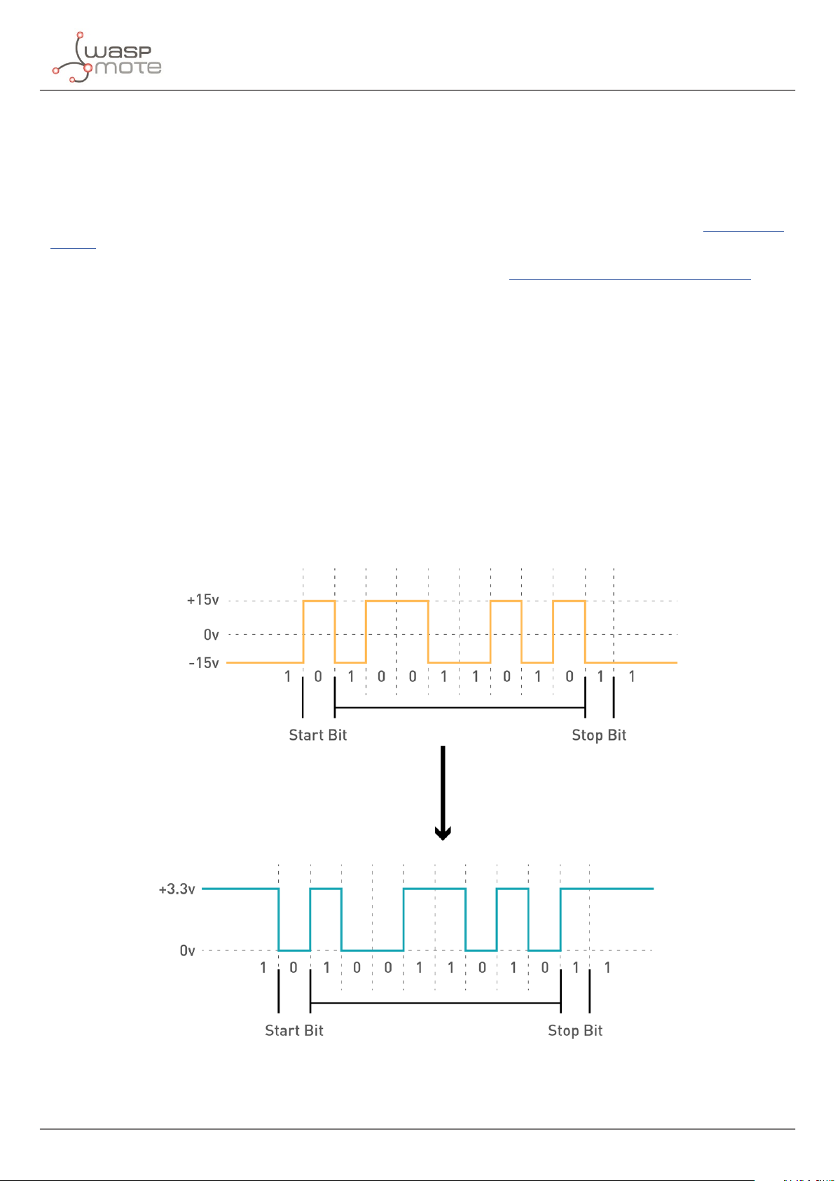
The IEEE RS-232 standard denes electrical, signal timing, and size connectors. Use of a common ground, limits RS-232 to
applications with relatively short cables. RS-232 connection consisting only of transmit data, receive data, and ground. RS-232
protocol uses bipolar signal. Valid signals are ±3 to +15 volts, the ±3V range is not a valid RS-232 level. Data signals between -3V
and -15V represents a logic 1. The logic 0 is represented by a voltage of between +3 V and +15 V.
Figure : RS-232 voltage conversion
-4- v7.1
Page 5

Introduction
Serial transmission requires synchronization. A logic 0 is sent as a start bit for the synchronization, followed by normally eight
bits. After the data itself, a parity bit is sent. It is optional and it can be chosen to have even or odd parity. Finally a stop bit is sent.
This is normally one bit long and is used to signify the end of a particular byte. Sometimes two stop bits are required. This is an
option that can be set on some equipments.
This list includes some of the more common uses of the standard:
• Dial-up modems
• GPS receivers (typically NMEA 0183 at 4,800 bit/s)
• Bar code scanners and other point of sale devices
• LED and LCD text displays
• Satellite phones, low-speed satellite modems and other satellite based transceiver devices
• Flat-screen (LCD and Plasma) monitors to control screen functions by external computer, other AV
• components or remotes
• Test and measuring equipment such as digital multimeters and weighing systems
• Updating Firmware on various consumer devices
• Some CNC controllers
• Uninterruptible power supply
• Stenography or Stenotype machines
• Software debuggers that run on a 2nd computer
• Industrial eld buses
-5- v7.1
Page 6
Hardware
2. Hardware
The RS-232 / Modbus module has been tested with various devices and is compatible with the majority of commercial modules,
but this does not ensure the working with all of them. Be sure that the RS-232 module ts your technical requirements. The nal
user is the responsable to perform the task of communicatiing the RS-232 module with other commercial devices.
2.1. Electrical features
• Board power voltages: 3.3 V
• Maximum admitted voltage: -0.3 V to +6 V
• Typical data rate: 115200 bps
• Temperature range: [ 0 °C, 70 °C ]
• Dimensions: 33 x 31.5 mm
2.2. Connection diagram
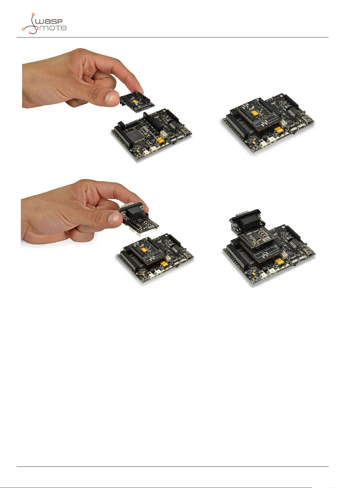
The RS-232 Serial / Modbus module uses the UART pins, RX and TX, for communication. The Expansion Board allows to connect
two boards at the same time in the Waspmote sensor platform. This means a lot of dierent combinations are possible using
any of the radios available for Waspmote (802.15.4, ZigBee, DigiMesh, 868 MHz, 900 MHz, LoRa, WiFi, GPRS, GPRS+GPS, 3G, 4G,
Sigfox, LoRaWAN, Bluetooth Pro, Bluetooth Low Energy and RFID/NFC) and the RS-232 module.
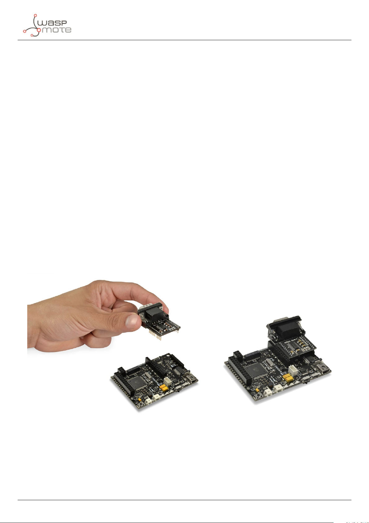
In the next photo you can see the available sockets along with the UART assigned. The RS-232 module can be connected
normally on socket 0, and in socket 1 with the Expansion Board.
Figure : RS-232 in socket0
-6- v7.1
Page 7
Hardware
Figure : RS-232 in socket1
The RS-232 Serial / Modbus module can be used with two dierent protocols:
• 1. RS-232 Serial standard (this is the scope of this guide)
• 2. Modbus protocol (which adds some features; see the Modbus Communication Guide for more details)
-7- v7.1
Page 8
Hardware
2.3. Consumption
RS-232 module uses a low power transceiver. The board is guaranteed to run at data rates of 120 kbps while maintaining RS-232
output levels. The next table shows the consumption at various baud rates.
Baud rate (bps) Consumption (mA)
300 1,65
600 1,65
1200 1,65
2400 1,67
4800 1,67
9600 1,72
19200 1,8
38400 1,9
57600 2,0
115200 2,26
Figure : RS-232 consumption table
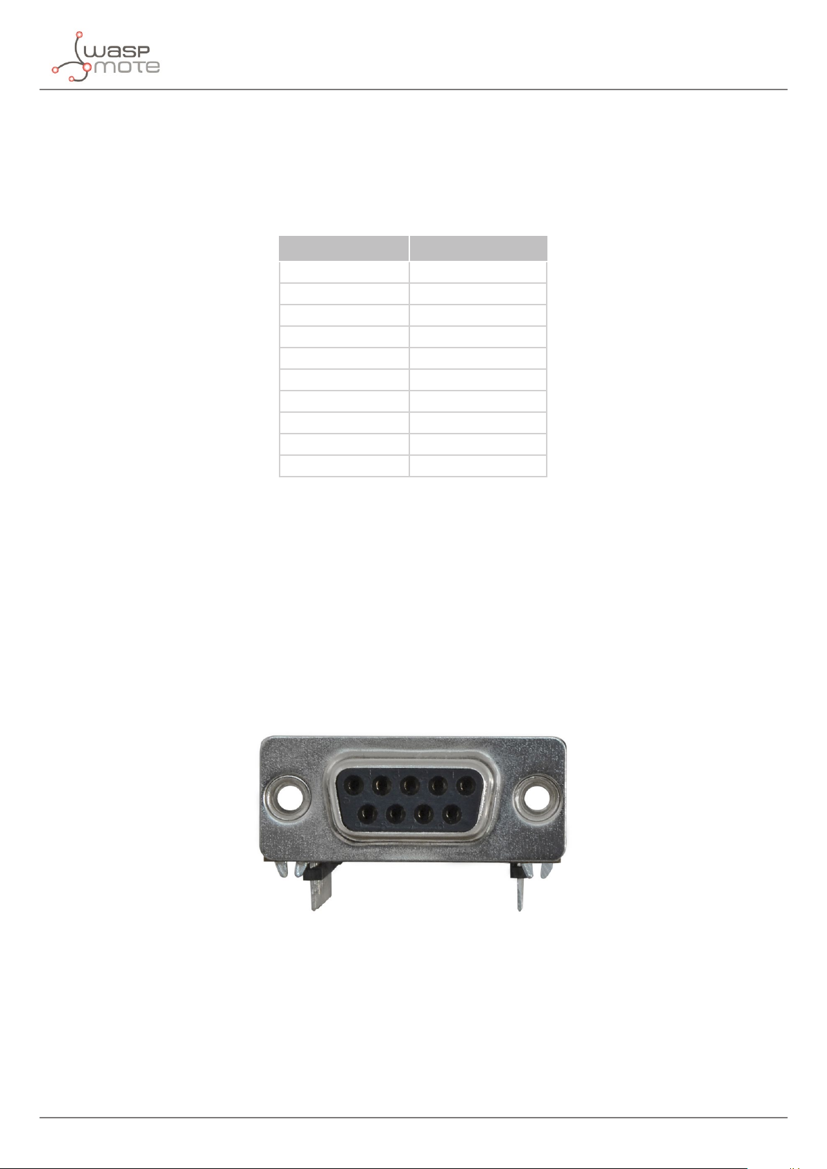
2.4. Connector
The standard recommends but does not make mandatory the D25-pin connector. In the RS-232 module, the connector is a
DB9 female. The RS-232 module uses pin 2 to receive data, 3 to transmit and ground pin. The DB9 connector is used in many
applications; for example, any PC has a serial DB9 connector. It provides size and cost benets. Also the RS-232 9-pin conguration
is sucient in most circumstances, because many of the lines available for RS-232 signaling are rarely used. This means that the
DB9 connector is able to provide all the required connectivity for most applications.
Figure : DB9 connector
-8- v7.1
Page 9
Hardware
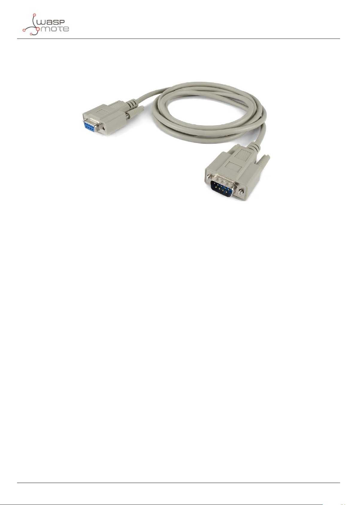
The RS-232 module comes with a standard male-female DB9 cable. This cable is useful for connecting the module to other RS232 devices which have a DB9 male connector.
Figure : Male-female DB9 cable
-9- v7.1
Page 10
Dual radio with Expansion Board
3. Dual radio with Expansion Board
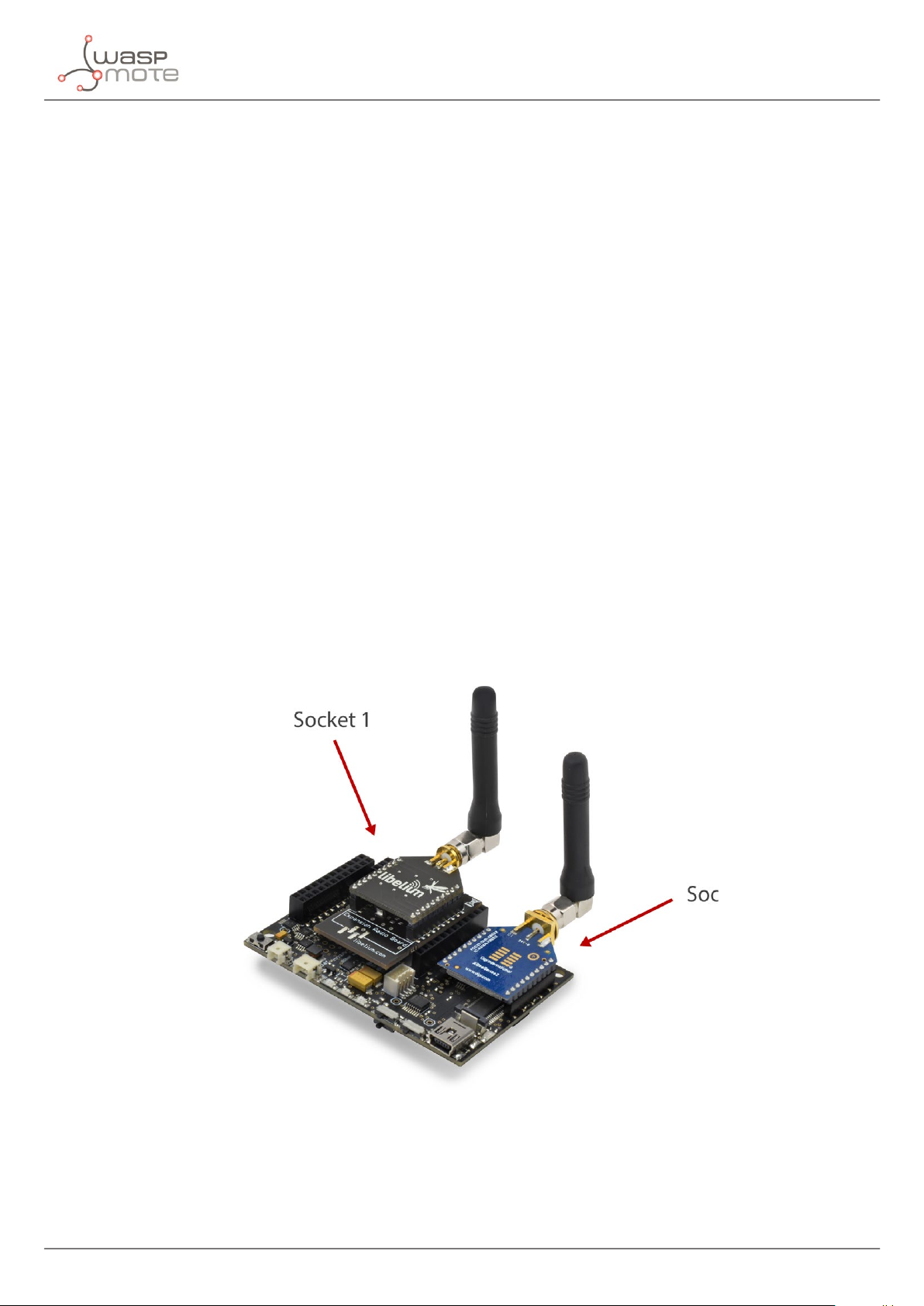
3.1. Expansion Radio Board
The RS-232 module can use the Expansion Radio Board. The Expansion Board allows to connect two communication modules
at the same time in the Waspmote sensor platform. This means a lot of dierent combinations are possible using any of the
wireless radios available for Waspmote: 802.15.4, ZigBee, DigiMesh, 868 MHz, 900 MHz, LoRa, WiFi, GPRS, GPRS+GPS, 3G, 4G,
Sigfox, LoRaWAN, Bluetooth Pro, Bluetooth Low Energy and RFID/NFC. Besides, the following Industrial Protocols modules are
available: RS-485/Modbus, RS-232 Serial/Modbus and CAN Bus.
Some of the possible combinations are:
• LoRaWAN - GPRS
• 802.15.4 - Sigfox
• 868 MHz - RS-485
• RS-232 - WiFi
• DigiMesh - 4G
• RS-232 - RFID/NFC
• WiFi - 3G
• CAN Bus - Bluetooth
• etc.
Remark: GPRS, GPRS+GPS, 3G and 4G modules do not need the Expansion Board to be connected to Waspmote. They can be
plugged directly in the socket1.
Figure : Waspmote with XBee radio on socket 0 and WiFi module on socket 1
-10- v7.1
Page 11

Dual radio with Expansion Board
The API provides a function to initialize the RS-232 module, it is called ON(socket). This function supports a new parameter
which permits to select the socket. It is possible to choose between socket0 and socket1.
An example of use the initialization function is the following:
Selecting socket0: W232.ON(SOCKET0);
Selecting socket1: W232.ON(SOCKET1);
The rest of functions are used the same way as they are used with older API versions. In order to understand them we recommend
to read this guide.
Warnings:
• Avoid to use DIGITAL7 pin when working with the Expansion Board. This pin is used for setting the XBee into sleep mode.
• Avoid to use DIGITAL6 pin when working with the Expansion Board. This pin is used as power supply for the Expansion
Board.
• Incompatibility with Sensor Boards:
- Agriculture v30 and Agriculture PRO v30: Incompatible with Watermark and solar radiation sensors
- Events v30: Incompatible with interruption shift register
- Gases v30: DIGITAL6 is incompatible with CO2 (SOCKET_2) and DIGITAL7 is incompatible with NO2 (SOCKET_3)
- Smart Water v30: DIGITAL7 incompatible with conductivity sensor
- Smart Water Ions v30: Incompatible with ADC conversion (sensors cannot be read if the Expansion Board is in use)
- Gases PRO v30: Incompatible with SOCKET_2 and SOCKET_3
- Cities PRO v30: Incompatible with SOCKET_3. I2C bus can be used. No gas sensor can be used.
-11- v7.1
Page 12

RS-232 on Plug & Sense!
4. RS-232 on Plug & Sense!
The RS-232 protocol is available for Plug & Sense! as a secondary communication module. This is an optional feature. The RS-232
module is placed on socket 0 by default, being accessible through an additional and dedicated socket on the antenna side of
the enclosure. On the other hand, the main radio interface of the Plug & Sense! device is placed on socket 1.
Figure : Industrial Protocols available on Plug & Sense!
The user can choose between two probes to connect the RS-232 interface: A standard DB9 connector and a waterproof terminal
block junction box. These options make the connections on industrial environments or outdoor applications easier.
Figure : DB9 probe connected to Plug & Sense!
-12- v7.1
Page 13

RS-232 on Plug & Sense!
Figure : Terminal box probe connected to Plug & Sense!
The RS-232 signals are wired on the female DB9 connector and on the Terminal box according to the next table:
RS-232
Terminal box probe DB9
- - 1
RX RX 2
TX TX 3
- - 4
GND GND 5
- - 6
- - 7
- - 8
- - 9
Figure : Wiring of RS-232 signals on Plug & Sense!
-13- v7.1
Page 14
Applications
5. Applications
This module allows the user to interface the Waspmote ecosystem with RS-232 systems. Waspmote allows to perform three
main applications:
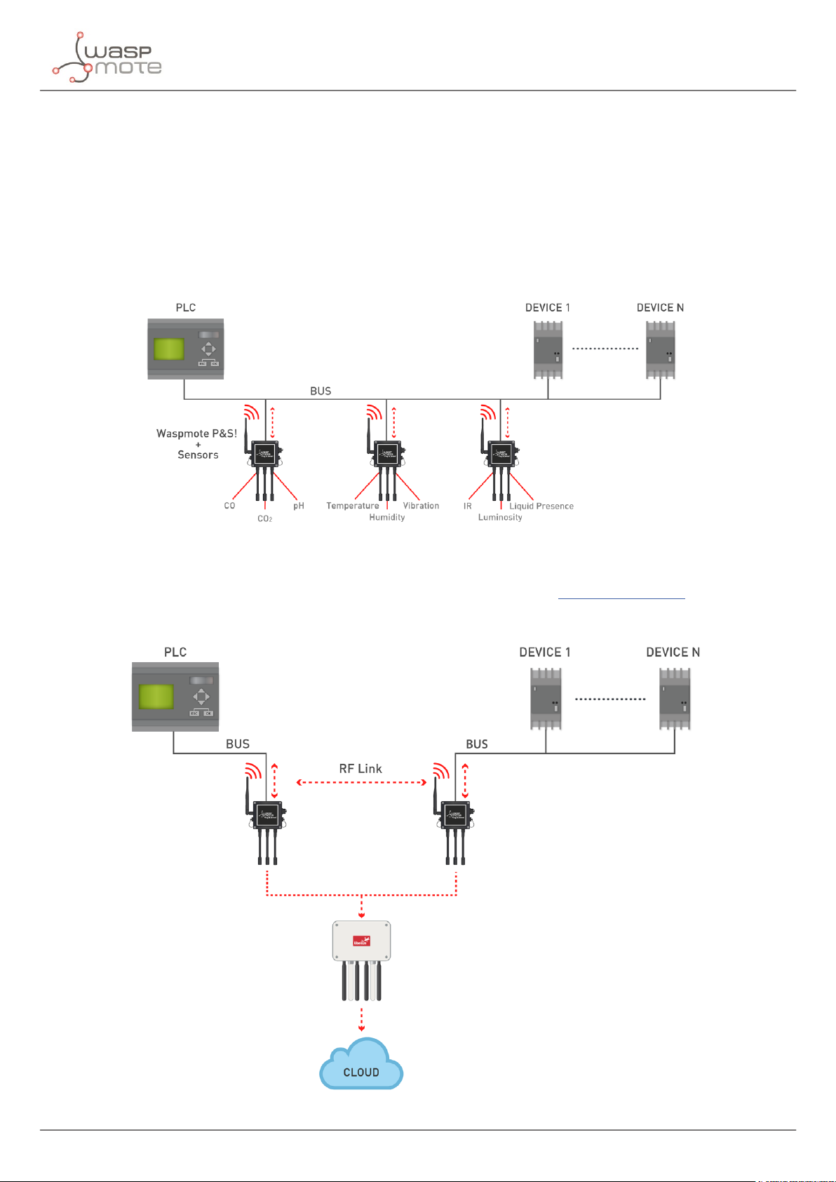
1º- Connect any sensor to an existing RS-232 device/network
Waspmote can be congured to work as a node in the network, inserting sensor data into the RS-232 bus already present.
Waspmote can obtain information from more than 70 sensors which are currently integrated in the platform by using specic
sensor boards (e.g: CO, CO2, temperature, humidity, acceleration, pH, IR, luminosity, etc). This way, the sensor information can be
read from any RS-232 device connected to the bus.
Figure : RS-232 in wireless sensor network applications
2º- Add wireless connectivity to RS-232 devices
Waspmote can be congured to read the information from the bus and send it to the Libelium IoT Gateway using any of the
wireless radio modules available: 802.15.4, 868 MHz, 900 MHz, WiFi, 4G, Sigfox and LoRaWAN, Bluetooth Pro, Bluetooth Low
Energy and RFID/NFC.
Figure : RS-232 wire replacement
-14- v7.1
Page 15

Applications
3º- Connect to the Cloud RS-232 devices
Waspmote can be congured to read the information coming from the RS-232 bus and send it wirelessly directly to the Cloud
using WiFi, GPRS, GPRS+GPS, 3G and 4G radio interfaces.
Figure : Cloud connection
-15- v7.1
Page 16

Libelium’s library
6. Libelium’s library
It is mandatory to include the RS-232 library when using this module. The following line must be introduced at the beginning
of the code:
#include <Wasp232.h>
Waspmote’s API RS-232 les:
• Wasp232.cpp
• Wasp232.h
APIs functions
- Private functions:
The following functions are executed inside the API functions. In normal conditions, the user must NOT manage or use them.
print(char c, uint8_t uart);
printNumber(unsigned long n, uint8_t base,
uint8_t uart);
Figure : RS-232 private functions
- Public functions:
ON(char socket);
OFF(void);
baudRateCong(unsigned long speed);
char read(void);
send(n);
int available(void);
ush(void);
parityBit(bool state);
Sends the data through the selected UART
Sends the data with a base through the selected UART
Powers the 232 module and opens the UART
Switches o the module and closes the UART
Sets the speed of asynchronous communication
Receives data through the UART
Sends data through the UART
Gets the number of bytes (characters) available for reading
Flushes the buer of incoming serial data
Enables or disables the parity bit
stopBitCong(uint8_t numStopBits);
uint8_t error(void);
Figure : RS-232 public functions
Selects the number of stop bits to be inserted by the transmitter
Detects a transmission error
-16- v7.1
Page 17

Library functions
7. Library functions
7.1. Library constructor
To start using Waspmote RS-232 library, an object from class Wasp232 must be created. This object, called W232, is created inside
Waspmote RS-232 library and it is public to all libraries. It is used through this guide to show how Waspmote RS-232 library
works. When creating this constructor, all the variables are dened with an initial value by default.
7.2. Switching the module on
The ON() function powers the RS-232 module and assigns the UART. The default baud rate is 115200 and it can be modied by
the function baudRateCong().
Example of use:
{
W232.ON(SOCKET0);
}
The same example but in the socket1:
{
W232.ON(SOCKET1);
}
See an example of use here:
http://www.libelium.com/development/waspmote/examples/rs-232-01-send-data
7.3. Switching the module o
This function switches o the RS-232 module and stops sending data frames. When you switch the module o, it is not necessary
to pass the socket as parameter. This information is already stored in an internal variable when you switch the module on.
Example of use:
{
W232.OFF();
}
-17- v7.1
Page 18

Library functions
7.4. Conguring communication speed
RS-232 speed communication can be congured with the values of the RS-232 standard. The RS-232 module has been tested at
300, 600, 1200, 2400, 4800, 9600, 14400, 19200, 38400, 57600 and 115200 bps. The maximum supported datarate in the RS-232
module is 115200 bps.
Example of use:
// Include always this library when you are using the Wasp232 functions
#include <Wasp232.h>
void setup()
{
// Power on the USB for viewing data in the serial monitor
USB.ON();
delay(100);
// Powers on the module and assigns the UART in socket1
W232.ON(SOCKET1);
delay(100);
// Congure the baud rate of the module
W232.baudRateCong(9600);
}
See an example of use here:
http://www.libelium.com/development/waspmote/examples/rs-232-01-send-data
7.5. Conguring the number of stop bits
The most common conguration used between computers is 8N1: eight bit characters, with one stop bit and no parity bit. With
the RS-232 module you can congure the communication mode with one or two stop bits using the stopBitCong() function.
Example of use with one stop bit:
{
W232.ON(SOCKET0);
W232.baudRateCong(9600);
W232.stopBitCong(1);
}
Example of use with two stop bits:
{
W232.ON(SOCKET0);
W232.baudRateCong(9600);
W232.stopBitCong(2);
}
See an example of use here:
http://www.libelium.com/development/waspmote/examples/rs-232-02-receive-data
-18- v7.1
Page 19

Library functions
7.6. Conguring the parity bit
Parity is used in many hardware applications to detect frame errors and is usually generated and checked by the interface
hardware. The RS-232 module uses:
• NONE: No parity bit
• EVEN: Even parity
• ODD: Odd parity
Parity can be enabled or disabled depending on communication requirements. For that purpose, the parityBit() function
permits to change this parameter.
Example of use with no parity:
{
W232.ON(SOCKET0);
W232.baudRateCong(9600);
W232.parityBit(NONE);
W232.stopBitCong(1);
}
Example of use with even parity enabled:
{
W232.ON(SOCKET0);
W232.baudRateCong(9600);
W232.parityBit(EVEN);
W232.stopBitCong(1);
}
Example of use with odd parity enabled:
{
W232.ON(SOCKET0);
W232.baudRateCong(9600);
W232.parityBit(ODD);
W232.stopBitCong(1);
}
See an example of use here:
http://www.libelium.com/development/waspmote/examples/rs-232-02-receive-data
-19- v7.1
Page 20

Library functions
7.7. Sending data
7.7.1. Sending a char
The most common way to send a character is to send it between single quotes (e.g. ‘p’).
Example of use:
{
char data = ‘p’;
W232.send(data);
}
You can also send char variables by declaring the corresponding ASCII code. For example, if you initialize a char with “123”, it
sends the corresponding ASCII “{“.
Example of use:
{
char data = 123;
W232.send(data);
}
7.7.2. Sending an integer
You can send an unsigned or signed integer using the same function. If an unsigned int is declared you can assign a value from
0 to 65535, and if the variable is signed the value can be between -32768 and 32767.
Examples of use:
{
unsigned int data = 12345;
W232.send(data);
}
{
int data = -12345;
W232.send(data);
}
7.7.3. Sending a string
The same function can be used for sending string of characters.
Example of use:
{
W232.send(“Hello world”);
}
See an example of use here:
http://www.libelium.com/development/waspmote/examples/rs-232-01-send-data
-20- v7.1
Page 21

Library functions
7.7.4. Sending with base
The send() function allows to represent the variable in a specic base. You can select binary, octal, byte, decimal, and
hexadecimal representation.
Example of use:
{
int data = 12345;
// Send 12345 in binary base. It prints 0110 000 0011 1001.
W232.send(data, BIN);
// Send 12345 in octal base. It prints 30071.
W232.send(data, OCT);
// Send 12345 in decimal base. It prints 12345.
W232.send(data, DEC);
// Send 12345 in hexadecimal base. It prints 3039.
W232.send(data, HEX);
}
7.7.5. Sending a long
Long variables can be sent also with the function send(). Long variables represents 32 bits or 4 bytes and and the send()
function allows signed and unsigned declaration.
Example of use:
{
unsigned long data = 1234567;
W232.send(data);
}
-21- v7.1
Page 22

Library functions
7.8. Receiving data
All received bytes are stored in the UART buer of the micro-controller. These bytes can be read with the function read(). This
function returns the read value from the buer.
Example of use:
{
if (W232.available())
{
while (W232.available())
{
char data = W232.read();
USB.print(data);
}
}
}
The receive() function permits to receive all information in the reception buer so as to manage it. The contents are stored
in a buer that belongs to the ‘WaspRS232’ class. The buer is called _buffer and the length of the buer is stored in _length.
The function returns the number of bytes stored in the buer.
Example of use:
{
if(W232.receive() > 0)
{
USB.println(W232._buffer, W232._length);
}
}
See an example of use here:
http://www.libelium.com/development/waspmote/examples/rs-232-02-receive-data
-22- v7.1
Page 23

7.9. Knowing when new data is available
The available() function returns the number of bytes available in the UART buer.
{
if (W232.available())
{
while (W232.available())
{
char data = W232.read();
USB.print(data);
}
}
}
See an example of use here:
http://www.libelium.com/development/waspmote/examples/rs-232-02-receive-data
7.10. Flushing buer
Library functions
Flushes the buer of incoming serial data. The function ush() waits for outgoing data to transmit before clearing the buer
contents.
Example of use:
{
W232.ush();
}
-23- v7.1
Page 24
Certications
8. Certications
Libelium oers 2 types of IoT sensor platforms, Waspmote OEM and Plug & Sense!:
• Waspmote OEM is intended to be used for research purposes or as part of a major product so it needs nal certication on
the client side. More info at: www.libelium.com/products/waspmote
• Plug & Sense! is the line ready to be used out-of-the-box. It includes market certications. See below the specic list of
regulations passed. More info at: www.libelium.com/products/plug-sense
Besides, Meshlium, our multiprotocol router for the IoT, is also certied with the certications below. Get more info at:
www.libelium.com/products/meshlium
List of certications for Plug & Sense! and Meshlium:
• CE (Europe)
• FCC (US)
• IC (Canada)
• ANATEL (Brazil)
• RCM (Australia)
• PTCRB (cellular certication for the US)
• AT&T (cellular certication for the US)
Figure : Certications of the Plug & Sense! product line
You can nd all the certication documents at:
www.libelium.com/certications
-24- v7.1
Page 25

Code examples and extended information
9. Code examples and extended information
For more information about the Waspmote hardware platform go to:
http://www.libelium.com/waspmote
http://www.libelium.com/development/waspmote
In the Waspmote Development section you can nd complete examples:
http://www.libelium.com/development/waspmote/examples
Example:
/*
* ------ [RS-232_01] RS-232 Send Data ------- *
* This sketch shows how to send data through RS-232 standard.
* This standard denes the electrical characteristics of drivers
* and receivers for use in digital systems. It does not specify
* or recommend any communications protocol. For a complete
* communication protocol, please see the Modbus examples.
*
* Copyright (C) 2015 Libelium Comunicaciones Distribuidas S.L.
* http://www.libelium.com
*
* This program is free software: you can redistribute it and/or modify
* it under the terms of the GNU General Public License as published by
* the Free Software Foundation, either version 2 of the License, or
* (at your option) any later version.
*
* This program is distributed in the hope that it will be useful,
* but WITHOUT ANY WARRANTY; without even the implied warranty of
* MERCHANTABILITY or FITNESS FOR A PARTICULAR PURPOSE. See the
* GNU General Public License for more details.
*
* You should have received a copy of the GNU General Public License
* along with this program. If not, see <http://www.gnu.org/licenses/>.
*
* Version: 0.2
* Design: David Gascon
* Implementation: Ahmad Saad
*/
//Include always this library when you are using the Wasp232 functions
#include <Wasp232.h>
void setup() {
// Power on the USB for viewing data in the serial monitor
// Note : if you are using the socket 0 for communication,
// for viewing data in the serial monitor, you should open
// the USB at the same speed
USB.ON();
delay(100);
// Powers on the module and assigns the UART in socket0
W232.ON(SOCKET0);
delay(100);
-25- v7.1
Page 26

Code examples and extended information
// Congure the baud rate of the module
W232.baudRateCong(115200);
// Congure the parity bit as disabled
W232.parityBit(NONE);
// Use one stop bit conguration
W232.stopBitCong(1);
delay(100);
// Hello message
USB.println(“RS-232 serial communication properly initialized.”);
USB.println(“Hello, this is RS-232 communication send example! “);
delay(100);
}
void loop() {
// Reading the analog input 1
int analog1 = analogRead(ANALOG1);
// Reading the analog input 2
int analog2 = analogRead(ANALOG2);
// Send data through RS-232 line
W232.send(“Data from analog1 input: “);
W232.send(analog1);
W232.send(“\n”);
W232.send(“Data from analog2 input: “);
W232.send(analog2);
W232.send(“\n”);
delay(2000);
}
-26- v7.1
Page 27

10. API changelog
Keep track of the software changes on this link:
www.libelium.com/development/waspmote/documentation/changelog/#RS_232
API changelog
-27- v7.1
Page 28

11. Documentation changelog
From v7.0 to v7.1:
• Added references to the integration of Industrial Protocols for Plug & Sense!
Documentation changelog
-28- v7.1
 Loading...